

Page 1
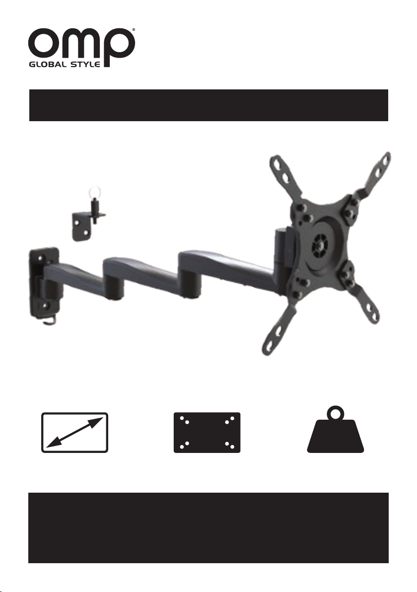
M7441 - CANTILEVER TV WALL
MOUNT WITH UNIVERSAL 3, 2
OR 1 ARM DUAL LOCK
INSTALLATION INSTRUCTIONS
TV SCREEN SIZE
13 - 40”
DO NOT EXCEED RECOMMENDED TV SCREEN SIZE OR WEIGHT.
PLEASE READ INSTRUCTIONS CAREFULLY BEFORE INSTALLATION.
VESA
COMPLIANT
75 x 75 to 200 x 200
CAUTION!
SERIOUS INJURY OR TV DAMAGE MAY OCCUR.
75 KG
KG
MAX WEIGHT
15 KG
Page 2

SAFETY INSTRUCTIONS - PLEASE READ
WARNING!
Read the entire instruction manual before you start installation & assembly.
• Do not begin the installation until you have read and understood all the
instructions and warnings contained in this installation sheet. If you have any questions
regarding any of the instructions or warnings, please contact your local distributor.
• This mounting bracket was designed to be installed and utilised ONLY as specied in
this manual. Improper installation of this product may cause damage or serious injury.
• This product should only be installed by someone with good mechanical ability who
fully understands this manual.
• Prior to installation ensure your desired installation location is t for purpose.
• We recommend installation to an internal panel. External walls may not offer the
necessary strength and may be used to route plumbing and cables. If in doubt
please consult vehicle manufacturer.
• This product is intended for indoor use only. Using this product outdoors could lead
to product failure and personal injury.
• Installers are responsible to provide hardware for other types of mounting situations.
• Installers must verify that the supporting surface will safely support the combined
weight of the equipment and all attached hardware and components.
• OMP declines all responsibility in the event of incident or accident if they are due to
non-observation of the installation instructions or installation error.
PAGE 2
Page 3
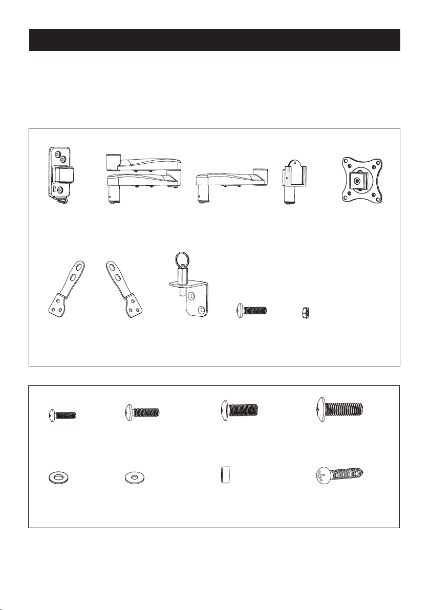
COMPONENT CHECKLIST
Important:
Ensure that you have received all parts according to the component checklist prior to
installation. If any parts are missing or faulty contact your local OMP distributor for a
replacement.
A
1 x Wall
Bracket
F
2 x VESA
Adaptor
M-A
4 x M4 x 14
M-E
4 x D5 Washer
B
1 x 1 & 2 Arm
Assembly
G
2 x VESA
Adaptor
M-B
4 x M5 x 14
M-F
4 x D8 Washer
H
1 x Lock
Assembly
C
1 x 3rd Arm
Assembly
M-C
4 x M6 x 14
M-G
8 x Small Spacer
I
8 x M5 x12
D
1 x VESA
Plate Bracket
J
8 x M5 x 2
E
1 x VESA
Plate
M-D
4 x M8 x 20
W-A
5 x ST5 x 25
PAGE 3
Page 4
• Prior to installation ensure your desired installation location is t for purpose.
WARNING !
• We recommend installation to an internal panel. External walls may not offer the necessary
strength and may be used to route plumbing and cables. If in doubt please consult vehicle manufacturer.
• Installers are responsible to provide hardware for other types of mounting situations.
• Installers must verify that the supporting surface will safely support the combined weight
of the equipment and all attached hardware and components.
NOTE - BEFORE INSTALLATION YOU WILL NEED TO DECIDE
HOW MANY ARM/S YOU WILL NEED IN YOUR APPLICATION, 3, 2, OR 1?.
THIS WILL DETERMINE HOW MUCH SPACE YOU WILL NEED
FOR THE FUNCTION OF THE BRACKET.
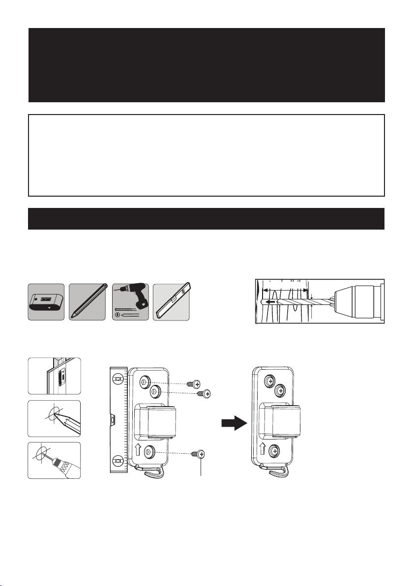
WOODEN PANEL MOUNTING
Fixings are provided for wooden panel mounting only, as illustrated below. It may be necessary to source
additional xings to mount the wall bracket using an alternative mounting arrangement as deemed appropriate
by the installer. It is the installers responsibility to ensure the xings are suitable for the medium the bracket is
being xed to.
20mm
4mm
1. Find and mark the exact location of mounting holes making sure the bracket is level.
1
2
3
W-A
PAGE 4
Page 5
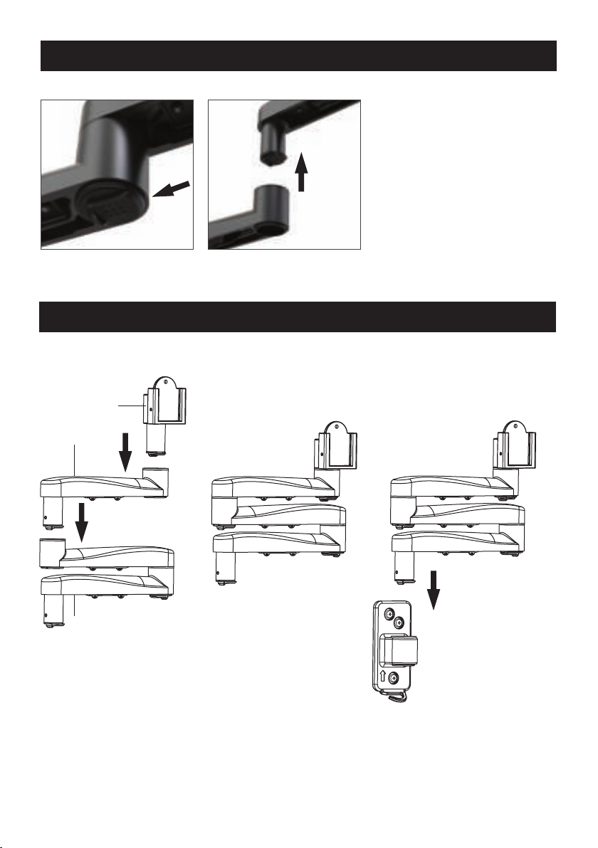
REMOVING OR ADDING ARM/S
Slide Catch Lift Arm
To add arm/s, reverse instruction.
FITTING VESA PLATE BRACKET AND ARM ASSEMBLY INTO WALL BRACKET
Note: 3 Arm option shown as an example
D
C
B
PAGE 5
Page 6
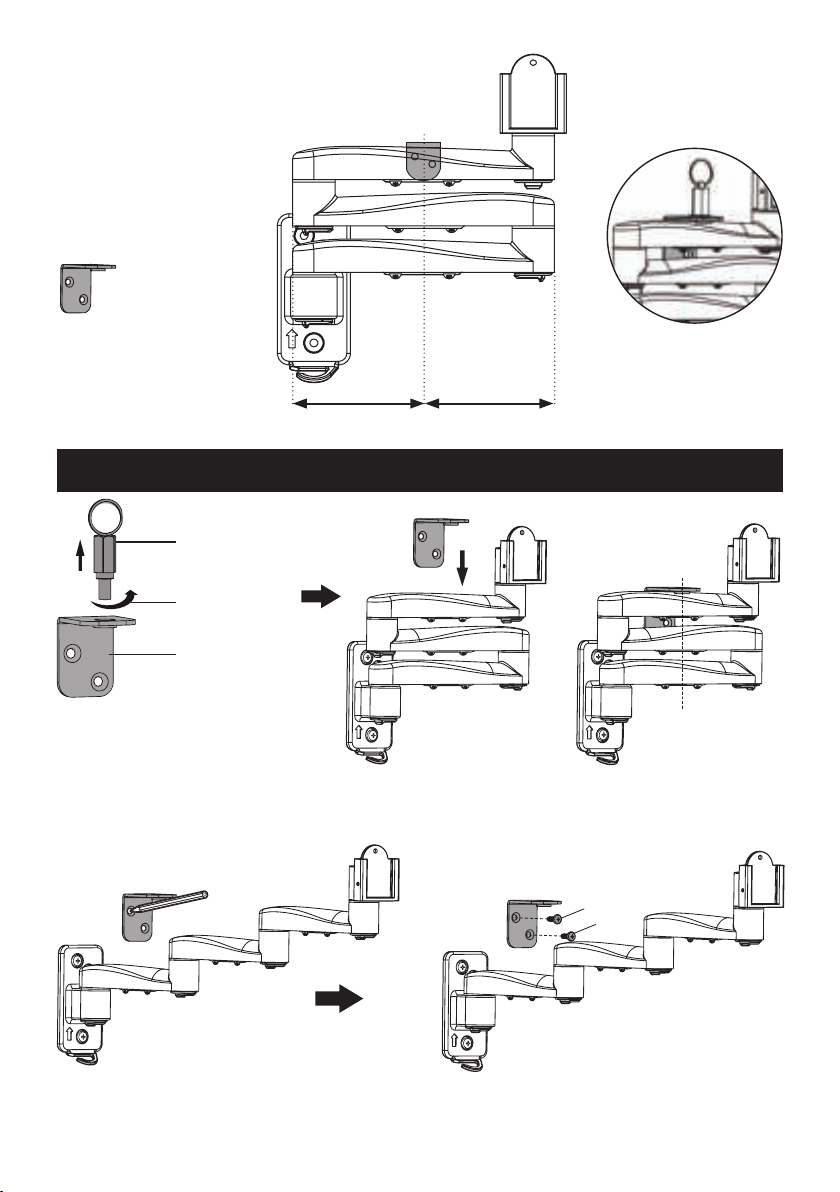
Note:
Before installing the lock assembly
please take note of the position.
X = Y reference
Note - Position the Lock Plate
close to the arm to ensure the
lock pin has maximum
engagement to hold arm.
X
INSTALLING THE LOCK ASSEMBLY - FOR 3 ARMS
Spring Lock
Loosen
Lock Plate
1. Remove the plug.
2. Fold the arms to make the
arms parallel with the wall.
Y
Centre
(X=Y)
3. Position the Lock Plate
making sure its central.
(See above).
W-A
W-A
4. Unfold the arms and use the Lock Plate
to mark the two mounting holes.
PAGE 6
5. Fix the Lock Plate to the wall using the W-A screws.
6. Replace the Spring Lock.
Page 7
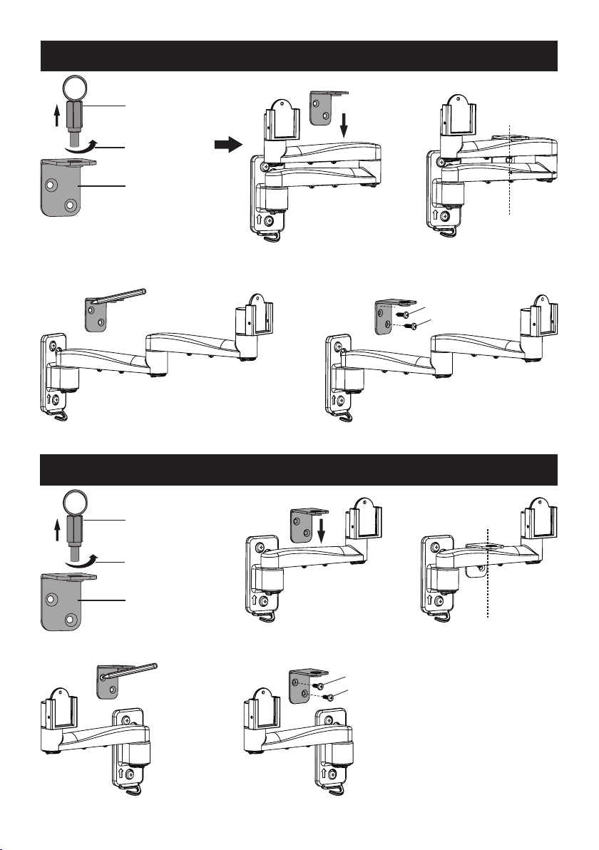
INSTALLING THE LOCK ASSEMBLY - FOR 2 ARMS
Spring Lock
Loosen
Lock Plate
1. Remove the plug.
4. Unfold the arms and use the Lock Plate
to mark the two mounting holes.
2. Fold the arms to make the
arms parallel with the wall.
INSTALLING THE LOCK ASSEMBLY - FOR 1 ARM
Spring Lock
Centre
(X=Y)
3. Position the Lock Plate
making sure its central.
(See opposite page above).
W-A
W-A
5. Fix the Lock Plate to the wall using the W-A screws.
6. Replace the Spring Lock.
Centre
(X=Y)
Loosen
Lock Plate
1. Remove the plug.
4. Unfold the arms and use the Lock Plate
to mark the two mounting holes.
2. Fold the arm to make the
arm parallel with the wall.
W-A
W-A
5. Fix the Lock Plate to the wall using the W-A screws.
6. Replace the Spring Lock.
3. Position the Lock Plate
making sure its central.
(See opposite page above).
PAGE 7
Page 8
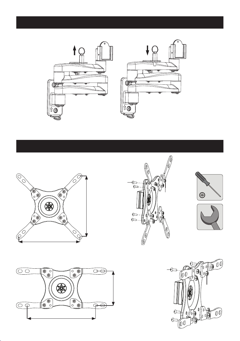
USING THE ASSEMBLY LOCK
Note: 3 arm option
shown as an example.
1. To release - Use the spring lock to release the
arm/s and postition your TV Bracket
1. Pull to release. 2. Replace to lock.
ASSEMBLING THE VESA ADAPTORS
VESA 200 x 200
2. To lock - Fold the arms and engage the spring lock to
avoid the arms moving whilst driving.
H
I
200
VESA 200 x 100
PAGE 8
200
200
100
H
I
Page 9
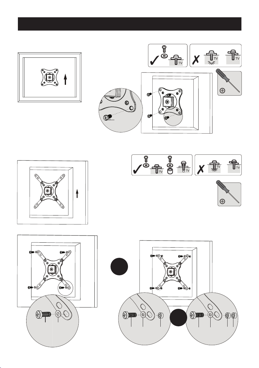
INSTALLING THE VESA PLATE
VESA 75 x 75 to 100 x 100
Top of the TV
VESA 200 x 200
Top of the TV
M-A
M-B
M-A
M-B
M-C
M-E
M-F
OR
M-D M-F
M-G
OR
M-D M-F M-G
PAGE 9
Page 10
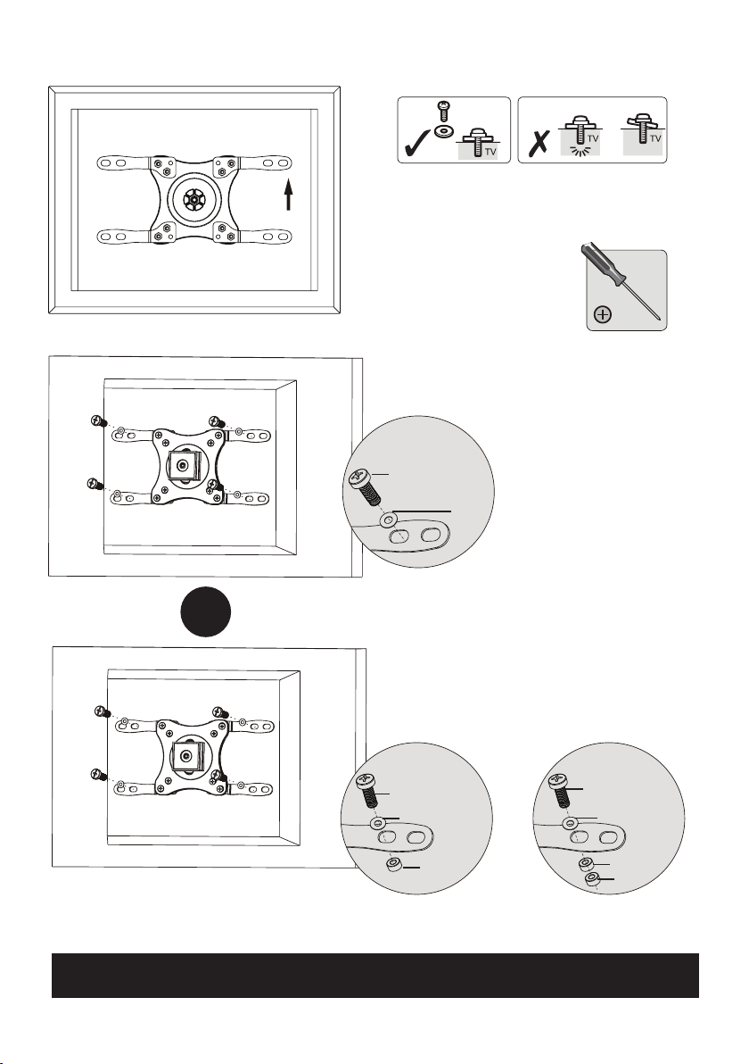
VESA 200 x 100
Top of the TV
M-A
M-B
M-C
M-E
M-F
OR
Screw the VESA plate onto the TV
Tighten all screws but do not over tighten
PAGE 10
M-D
M-F
M-G
M-D
M-F
M-G
M-G
Page 11
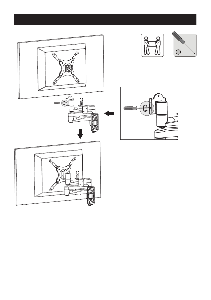
MOUNTING THE TV ONTO THE WALL PLATE
1. First loosen the small
screws x 2 either side
of the TV mount bracket.
2. For safety please lock the TV by
screwing the small screws x 2 either
side of the TV mount bracket.
PAGE 11
Page 12
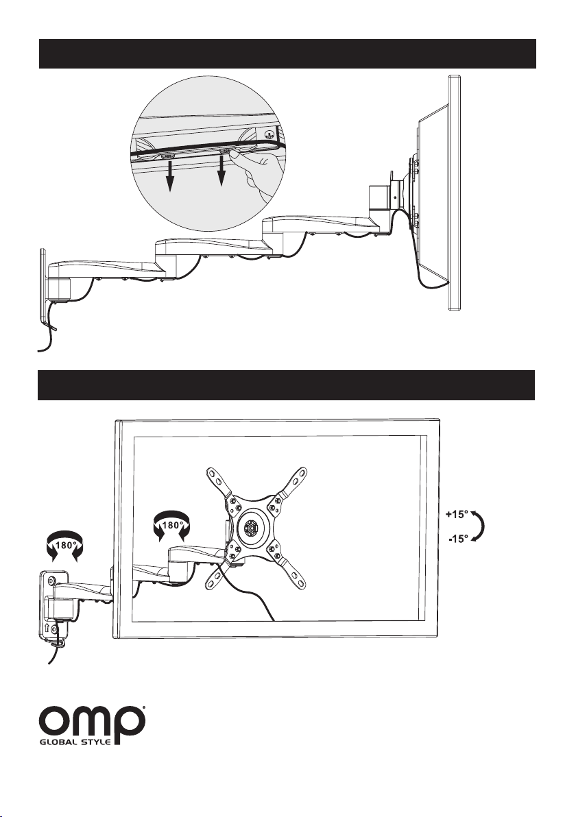
CABLE MANAGEMENT
Connect the cables to your TV and route through the cable clips along the arms.
Note: Leave slack in the cables for the arm movement
ADJUSTMENT
M7441INS Iss 2
Adjust to the desired position or tilt.
Common Lane, Setchey,
Kings Lynn, Norfolk, PE33 0AT, England.
T: +44 (0) 1553 813300
E: [email protected]
W: www.ompglobal.co.uk
 Loading...