

Page 1
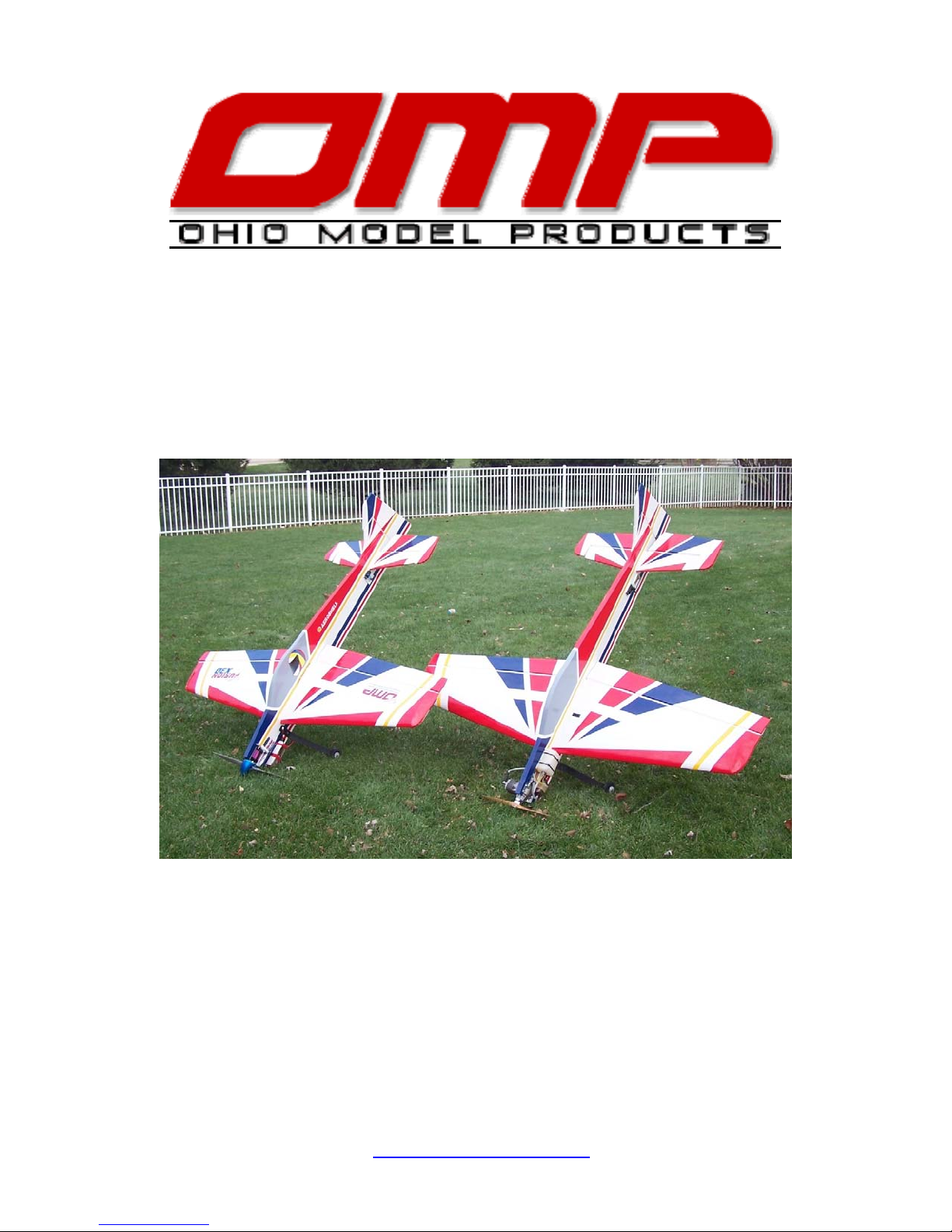
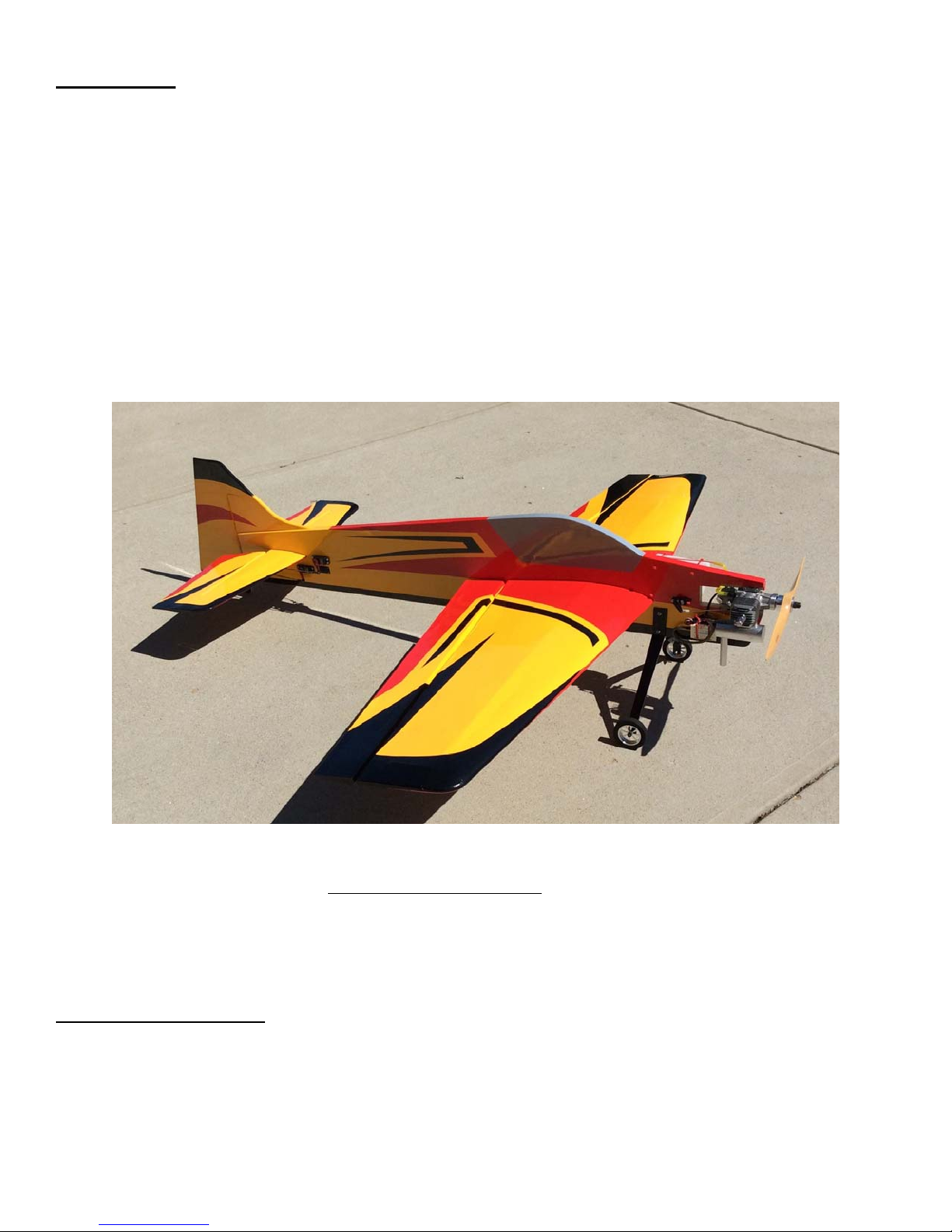
70” FUSION
Instruction Manual
E50-E60 motor with 1900-2100 Watts
OHIO MODEL PRODUCTS, 199 Stratford Lane, Xenia, Ohio 45385, (937) 372-0603
Wingspan: 70"
Wing Area: 1045 sq. in.
Length: 69.5"
Approx. Weight: 7.25-7.75 lbs.
Engine: 1.20 glow, 20 cc gas
www.ohiomodelplanes.com
Page 2

Thank you for purchasing the OMP Fusion Profile. In our continuing effort to bring the best in
performance to our customers, we have redesigned the highly popular 67” Fusion into a 70” model for both
electric and gas/glow versions. The Fusion was the first profile designed to perform precise and crisp pattern
and IMAC maneuvers effortlessly yet still retain the capability to let out all the stops for ultimate 3d flying.
Now you can evolve your flying skills to a new level without having to spend a fortune on an expensive pattern
or IMAC airplane as the Fusion offers the best of both worlds to the sport flyer at every level. You can learn
precision and 3D aerobatics at a very reasonable cost using reasonably priced radio equipment and readily
available glow or gas size sport motors and E50 size electric motors. Our Fusion offers the perfect blend of
aerodynamic design parameters which allow you to perform anything you can imagine: F3A pattern, IMAC
sequences, elevators, positive and inverted harriers, waterfalls, knife edge spins, positive and inverted flat spins,
and of course rock solid hovers and torque rolls. I hope you will enjoy the Fusion X3D Profile as much as we
have – Mike Pilkenton and John Drake.
A QUICK WORD ABOUT SAFETY AND RADIO CONTROL FLYING MODELS
With radio control aircraft, like any hobby or sport, there are certain risks. The operator of these models
is responsible for these risks. If misused or abused, you may cause serious bodily injury and/or damage to
property. With this in mind, you will want to be certain that you build your model carefully and correctly. If
you are not an experienced flier, have your work checked and ask for help in learning to fly safely. This model
aircraft is not a toy and must be operated and flown in a safe manner at all times. Always perform a pre-flight
check of the model including all control surfaces, proper function of the radio gear, structure, radio range, and
any other area relating to the safe operation of this aircraft.
Models are not insurable but operators are. You can obtain coverage through membership in the
Academy of Model Aeronautics (AMA). For an AMA information package call 1-800-435-9262, ext. 292 or
visit the AMA website at "
www.modelaircraft.org".
OHIO MODEL PRODUCTS GUARANTEE AND CUSTOMER SERVICE
Ohio Model Products guarantees this ARF to be free from defects in both material and workmanship at the
date of purchase. This does not cover any parts damaged by use, misuse, modification, or long term storage. In
no case shall OMP's liability exceed the original cost of this kit. Because OMP has no control over the final
assembly or equipment/components used in the final assembly, no liability shall be assumed for any damage
resulting from the use of this model by the user. By the act of using the final assembled model, the user accepts
all resulting liability. If at the time of purchase, you should find any missing or damaged parts, or have any
questions about this product, please contact us at [email protected] or call OMP at (937) 372-0603.
ENGINES, PROPELLERS AND MUFFLERS
The recommended engine range for the Fusion is a 1.20 glow, a 20 cc gas, or E50-E60 size electric
motors that will produce 1900-2100 watts. There are a tremendous variety of engines available and each type
has its own advantages and disadvantages. Selecting the proper size of propeller for your particular engine is a
very important part of the whole set up. The Fusion, as all high performance 3d aircraft, was designed to use
low pitch props. What you need is air flow and vertical performance, not straight-line speed. We recommend
using the lowest pitch, highest diameter propeller you can find for your particular engine. The use of high pitch
props can cause air "cavitation" around the prop blades during hovering or slow vertical maneuvers. Air
cavitation may sound neat but it's not what you want because the prop is no longer biting into "clean air" and
you may loose altitude very quickly; so be wise when selecting your prop. Also, please be aware that the power
available in today's engines, while tremendously advantageous for 3d flying, can quickly lead to over speeding
the plane. Manage your throttle wisely to prevent over speeding and stressing the airframe.
Page 3
Note: As with all ARFs, it’s a good idea to read all the instructions and study the parts
before you begin construction. Make sure you have a flat and sturdy workbench and
follow all safety advice for the tools and adhesives you plan to use.
Also note that the assembly pictures are from both the Fusion ARF and various kit builds
however the assembly process is the same.
Building Supplies and Tools Required to Complete the Model:
• Thin and Medium CA
• CA Accelerator
• 5 minute Epoxy
• Hobby knife
• Screwdrivers
• Covering iron
• Engine and Prop
• Radio Gear
COVERING:
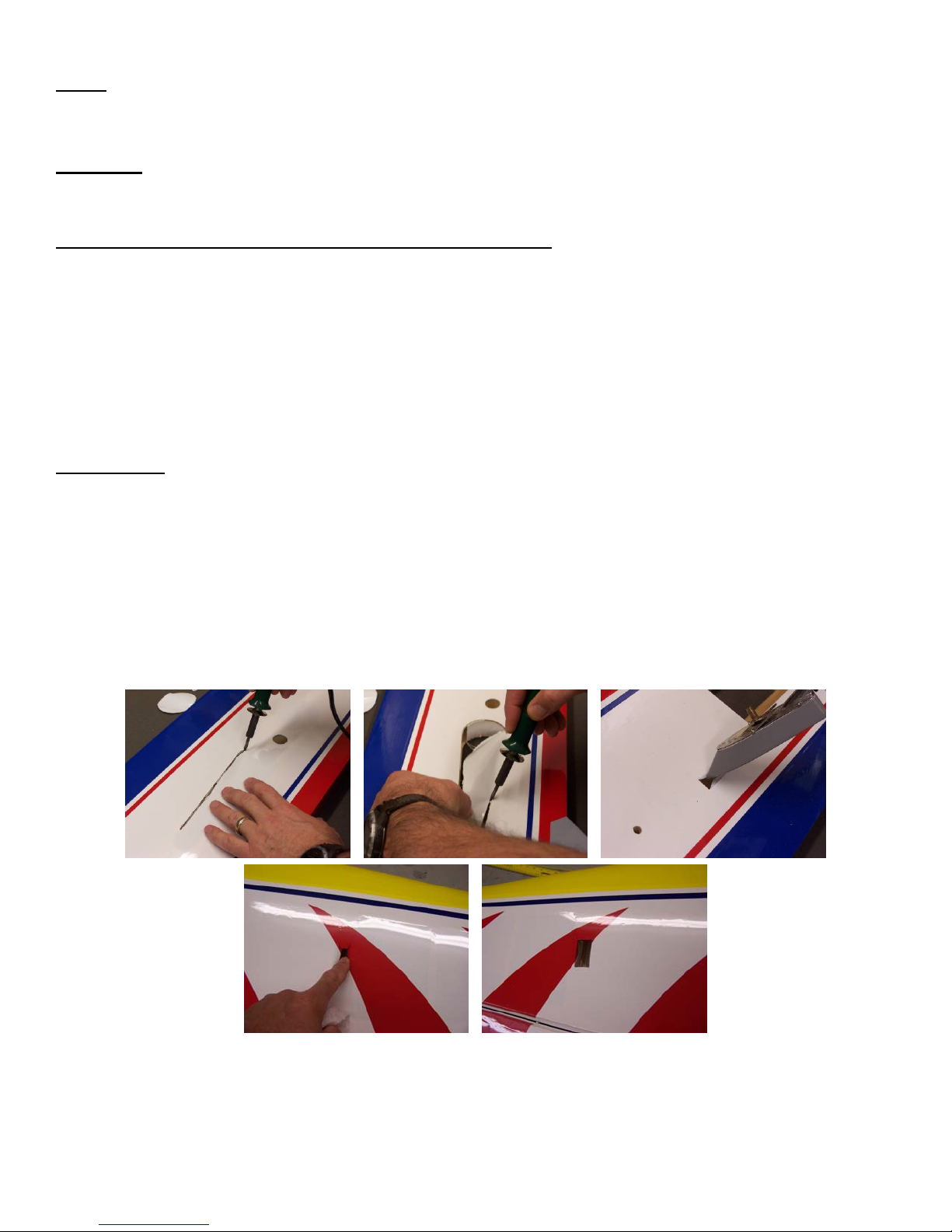
1. OMP recommends lightly going over all the covering with a covering iron set at medium temperatures.
With all ARFs, varying temperatures and transport delays can cause covering material to loosen over time.
Pay attention to all covering seams and make sure all are properly adhered to the model.
2. Carefully cut the covering away from the various openings on both sides of the fuselage. Servo openings in
the wings and fuselage should be cut from corner to corner and the covering ironed down on the inside.
Only cut the throttle servo opening on the right side of the fuselage. Other holes can be cut out using either
a sharp hobby knife or the tip of a hot soldering iron. The latter technique acts to seal the covering edges as
you cut away.
3. Cut the covering away from the hatch opening in the nose of the fuselage and iron down the covering
around the perimeter. A pre covered hatch is provided which can be secured with 4 screws. To properly
balance the model, the flight pack battery, ignition battery or other item may be placed in this hatch. For
example the author installed the gas engine ignition module into this hatch and used an IBEC system instead
of a separate ignition battery. With a sharp exacto knife, cut a small rectangular hole in the back side of the
Page 4
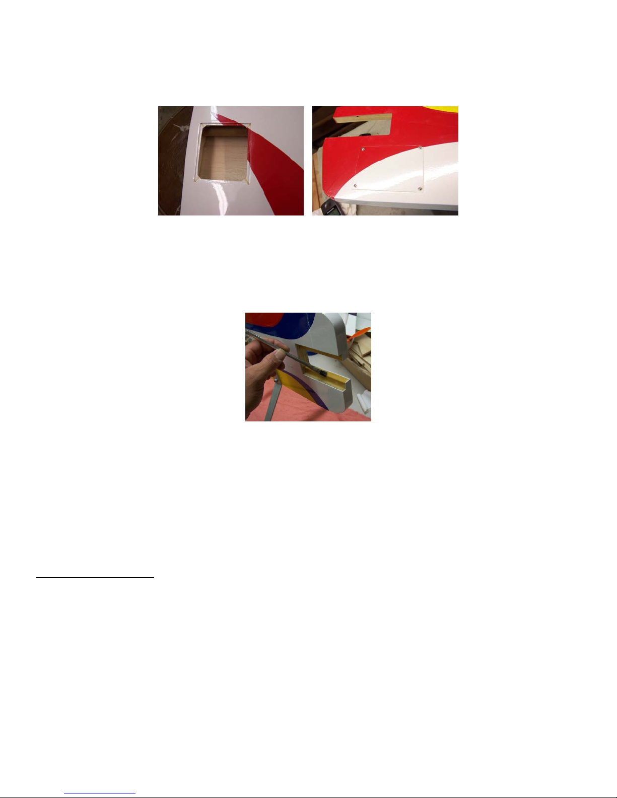
throttle servo opening big enough for a servo wire connector to pass through. Make a small notch in the
upper right hand corner of the nose battery hatch. If required, run the battery wire from the hatch opening to
the hole you cut in the back of servo opening and down the tunnel to the receiver.
4. Be sure to seal any exposed wood with a thin coating of epoxy to prevent engine oil from soaking in. This
is especially important around the engine compartment and servo openings with exposed areas. The Fusion
ARF already has a factory applied coating of epoxy around the engine mounting area. If you need to widen
the engine mounting rails be sure to reseal the wood.
5. Some modelers prefer to seal the hinge gaps using strips of appropriate covering or clear trim tape. We
have found this to be helpful with models intended for higher speed flight or models with unusually large
hinge gaps. OMP profiles utilize a very tight double beveled hinge line and do not normally require this
step. Sealing the hinge gaps is therefore left as an option for the modeler. If desired this can be
accomplished using strips of clear covering applied along the hinge lines after the surfaces have been
installed.
RADIO SELECTION:
You will require at least a 6-channel radio system with 5 standard size servos and one mini size servo
for the throttle. The Fusion can use servos ranging from 70 in-oz of torque up to 130 in-oz high speed digitals.
The use of higher speed more powerful servos will allow the pilot to fly the Fusion much more aggressively for
advanced aerobatics and 3D performance. To take full advantage of the flight performance, a radio system with
mixing capabilities is best. This will greatly enhance the maneuverability of your model. A good example
would be coupling the elevators to the flaps. This can be done in both directions. For example you can mix up
flaps with down elevator (and vise versa) for really tight turns or loops. This is commonly referred to as
flaperons" and requires the aileron servos to be plugged into separate channels, usually 1 and 6. You can also
"
mix up flaps with up elevators for quick descent elevators; this is referred to as "
spoilerons".
Page 5
AIRFRAME ASSEMBLY:
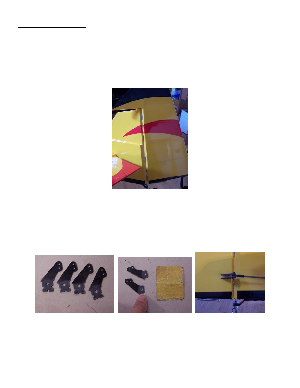
1. Flat nylon hinges are provided for this model and the slots have been pre-cut by the factory. Hint: clean the
hinges first with isopropyl alcohol to remove any plastic mold release agent prior to gluing in place. Also,
lightly sand them to take the shine off. Test fit the rudder and hinges (4 total) making sure it operates freely
with no binding. Make sure your hinges rotate freely at 90 degrees to the surface and are centered on the
hinge line. When satisfied, glue in place using epoxy making sure the hinge line is tight. Thoroughly clean
any excess epoxy away from the hinges using isopropyl alcohol and paper towels. Use masking tape to hold
the control surface in place with a tight hinge line while the glue cures.
2. Locate the Carbon fiber rudder horns (2) and choose which side to put the horns on. Either side is Ok,
however, remember the rudder servo has to be on the same side! Locate the two slots in the rudder for the
horns and carefully remove the covering only on the side that the horn will be on. Sand the tabs of the
control horns and test fit into the slots. It may be necessary to cut off some of the tab so that the horn fully
seats into the wood. It is very important that the horns align with each other and that the control rod pivot
point aligns over the hinge line. When satisfied, glue the horns in place using thin CA.
3. Locate the parts for the main landing gear. Two guide holes are provided in the fuselage for mounting the
main landing gear. Cut the covering away from these holes and mount the main landing gear using the
supplied bolts, washers, and lock nuts. Mount the wheels to the main gear by installing the supplied bolt
(bolt has a smooth shank on it) into the wheel, installing a nut on the bolt (tighten just enough to allow the
Page 6
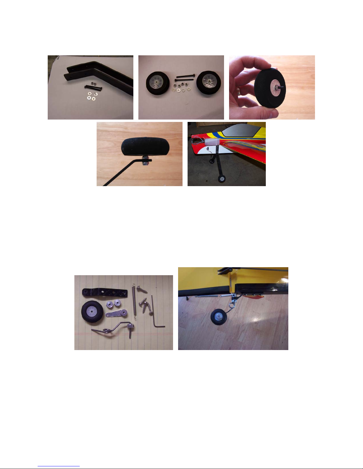
wheel to spin freely), inserting into the gear and then securing with a nylon insert lock nut on the inside of
the gear.
4. Locate the tail wheel parts as shown below. Install the tail wheel onto the spring wire and secure in place
using the supplied wheel collars. Install the third wheel collar onto the other end of the wire, next to the
spring section. Insert the wire end into the bottom of the bracket and secure the steering arm as shown. Cut
off any excess wire from the top of the assembly. Mount the tail wheel bracket to the hardwood mount in
the rear of the fuselage making sure the pivot point is aligned with the hinge line of the rudder. Hint: harden
the screw holes with thin CA before final assembly. The steering arm is secured to the bottom of the rudder
using the supplied spring and small wood screw. Again, be sure to harden the hole with thin CA prior to
final assembly.
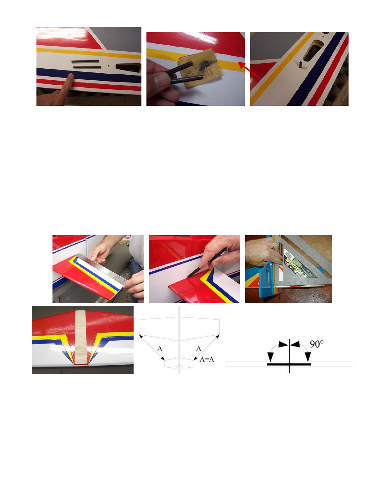
5. Using sandpaper, round off the ends of the carbon fiber wing anti-rotation pins to aid in installing the wings.
Install the pins into the fuselage making sure they are centered and extend equally on both sides of the
fuselage. Also make sure the pins are square to the fuselage. Once these pins are centered and square, wick
thin CA around the joints on both sides of the fuselage.
Page 7
6. Temporarily install the wings onto the fuselage making sure they are fully seated onto the fuselage. Tighten
the center wing bolt to make sure the wings are tight and square to the fuselage. The center bolt is inserted
through the left wing hatch and passes through the root rib, fuselage, and into the blind nut in the right wing.
7. Install and center the stabilizer making sure it is square to the fuselage and centered from side to side. Use a
T-square on the side of the fuselage to align the trailing edge of the stab or you can measure from the wing
tips to the corners of the stab to assure proper alignment. This distance should be equal on both sides. The
covering in the center of the stab has already been removed by the factory. Double check that no covering
extends into the glue joint. Mark the fuselage outline around the stab covering using a pen or pencil if and then
remove any excess if needed. If required, use a sharp x-acto blade and be extremely careful not to cut any of the
wood or you will weaken the stabilizer and cause possible failure.
8. Now reinstall the stabilizer and assure it is properly aligned, parallel to the wing, and centered in the
fuselage. Hold in place using tape and/or pins. When satisfied glue in place by wicking thin CA around the
joint. If desired, you can add a small filet of glue at the fuselage/stabilizer joint using thick CA or your
favorite adhesive.
9. Once the glue has cured on the stabilizer you can remove the wings. Test fit the elevators using the supplied
flat nylon hinges (3 per side) to check the fit. Follow the same hinging instructions as with the rudder.
When satisfied, glue the hinges in using epoxy. Make sure the hinges rotate freely 90 degrees from the
Page 8
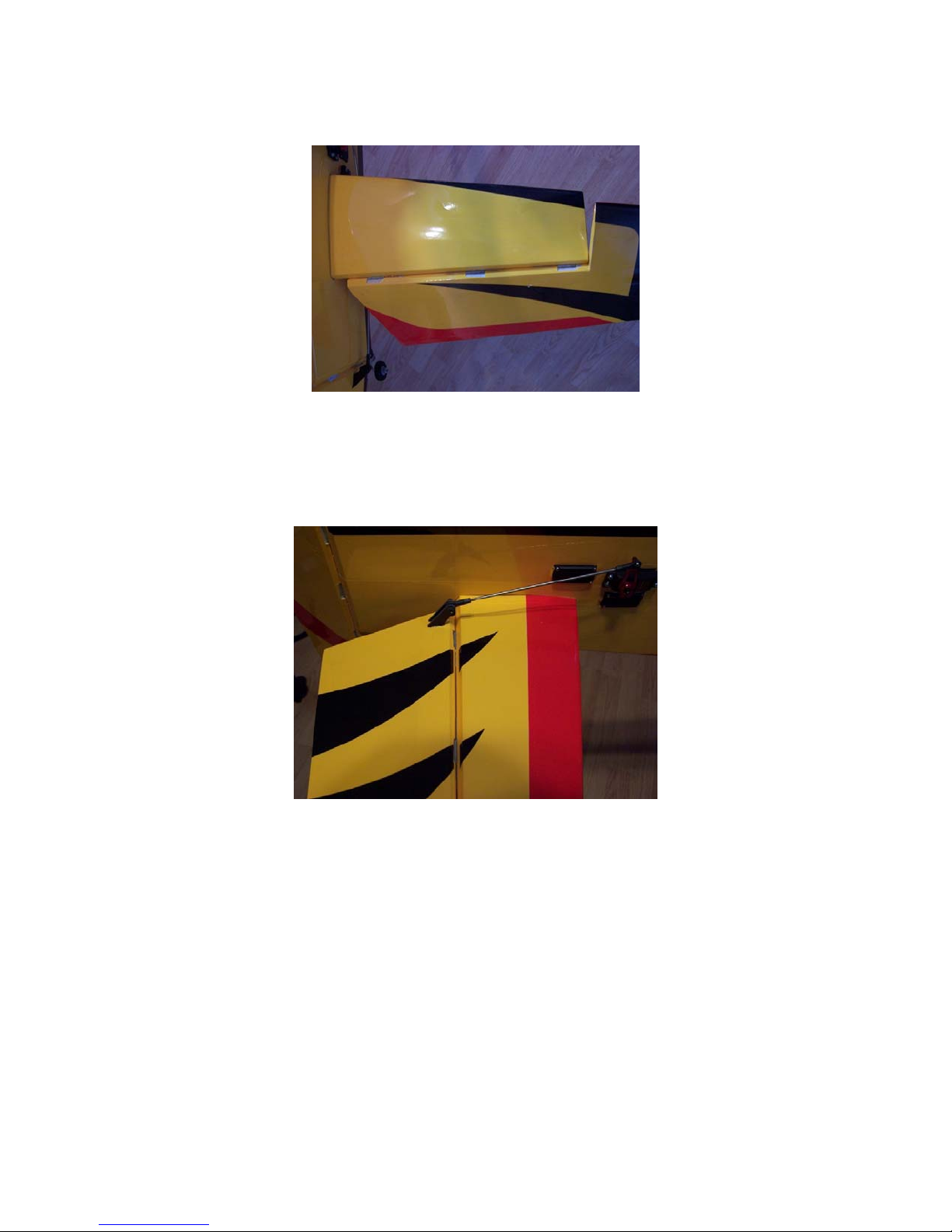
surface and are centered on the hinge line. Clean off any excess glue and tape the elevators in place while
the glue dries.
10. Now locate the carbon fiber horns (4) two for each side. Locate the two slots in the elevators and carefully
remove the covering to expose the slot on the bottom only. Prepare the horns the same way as the rudder
horns and glue in with epoxy or thin CA.
11. Now install the ailerons using the supplied hinges and the same technique as you did for the rudder and
elevators. Double check the operation and tape the ailerons in place until the glue cures. Install the control
horns in each wing likewise using the same technique as the previous surfaces.
Page 9
ENGINE, TANK, AND RADIO GEAR GAS/GLOW VERSION:
Note: If you have the electric version, scroll down to the Electric section for directions on how to install motor,
ESC and batteries.
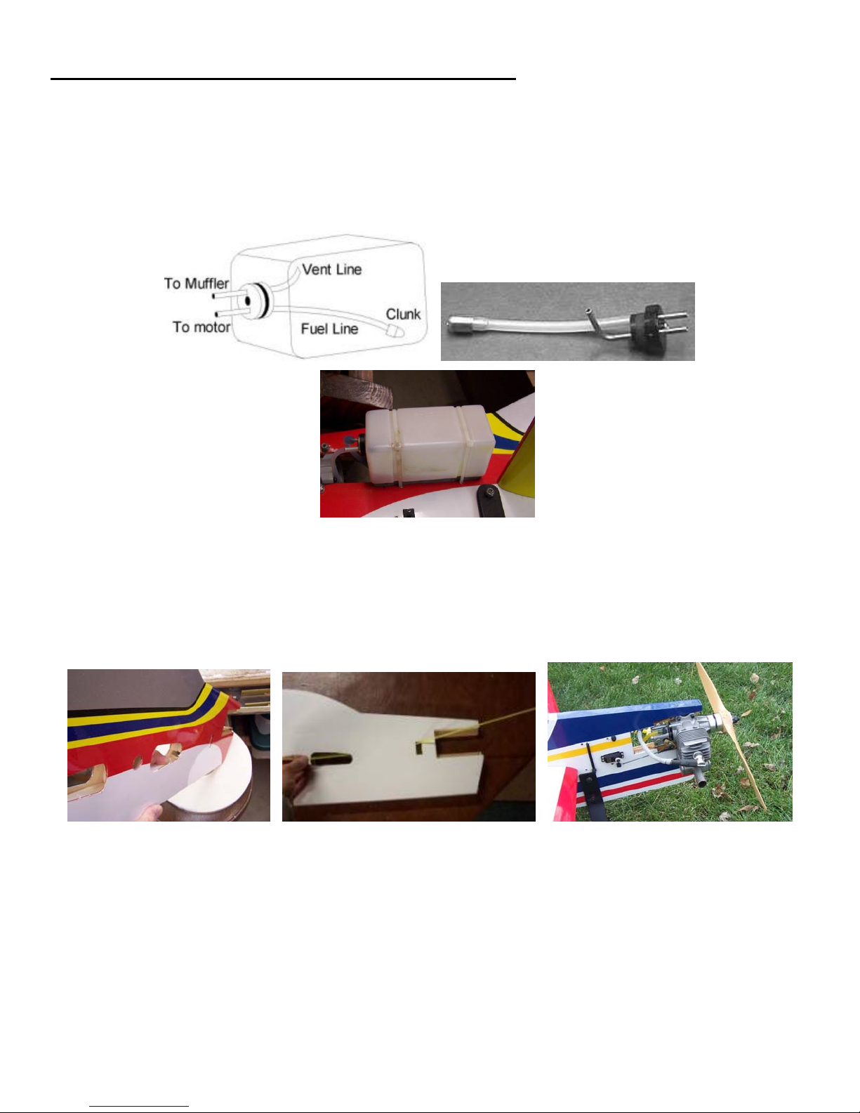
1. Locate the fuel tank and assemble the stopper, fuel lines, and tank clunk according the photo below.
Carefully bend the vent line upward toward the top of the tank. If you are using a gasoline engine just leave
the vent open and do not run it to the muffler. Mount the tank to the fuselage using the two tie wraps and
foam padding to reduce fuel foaming. NOTE: The tank provided is sized for a glow engine. If you are using
a gas engine, you might consider using a 6-8 oz tank.
2. Install the throttle servo into the opening in the right hand side of the fuselage. The cutout is sized for a
typical mini servo. If required, trim the opening larger to fit your servo. Feed the wire through the tunnel
provided and into the receiver hatch area. Use an extension if required and pull it through the tunnel using a
string or nylon pushrod taped to the servo lead.
3. Install the aileron servos in the wing using extensions as required. Hint: Make a small cable clamp out of
scrap balsa to help hold the end of the servo wire near the root of the wing.
Page 10
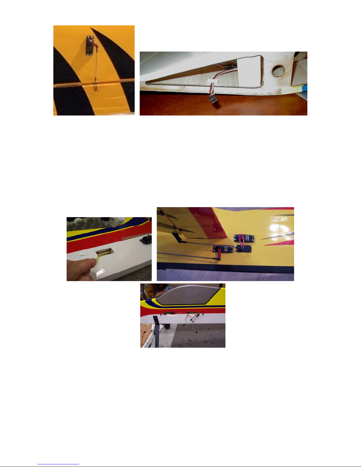
4. Install the tail servos into their respective sockets and pull the wires through the tunnel by taping the ends to
a piece of long nylon pushrod or similar semi-flexible wire. The two elevator servos are stacked one on each
side of the fuselage. The rudder servo is the back opening and make sure you put the rudder servo on the
same side as the rudder horn. Tape over the connectors to prevent inadvertent detachment and to prevent
the sharp plastic corners from getting snagged inside the tunnel as you pull the wires through the tunnel.
The rudder servo wire is fed through a hole into the elevator servo opening with a small access hole located
between the two elevator servos. Prevent the wires from getting pinched during your servo installation and
feed all wires forward into the aft fuselage opening between the wings.
5. Finish installing the control linkages to all the surfaces with the supplied pushrods, clevises and ball links.
The one longer control rod is for the rudder. Use proper geometry to assure optimal performance. Use the
sub trim and end point adjustment features of your radio to match centering and max throws of both ailerons
and elevators.
6. Now is a good time to check your center of gravity (cg) and decide where you want to mount the receiver,
battery(s) and engine. Trial fit your engine and mark the location for each mounting hole. The location can
be moved forward or aft depending on balance requirements. A tip is to use rubber bands to hold your
engine in place while your check the cg. Make sure you have the muffler and prop on the engine to get an
Page 11
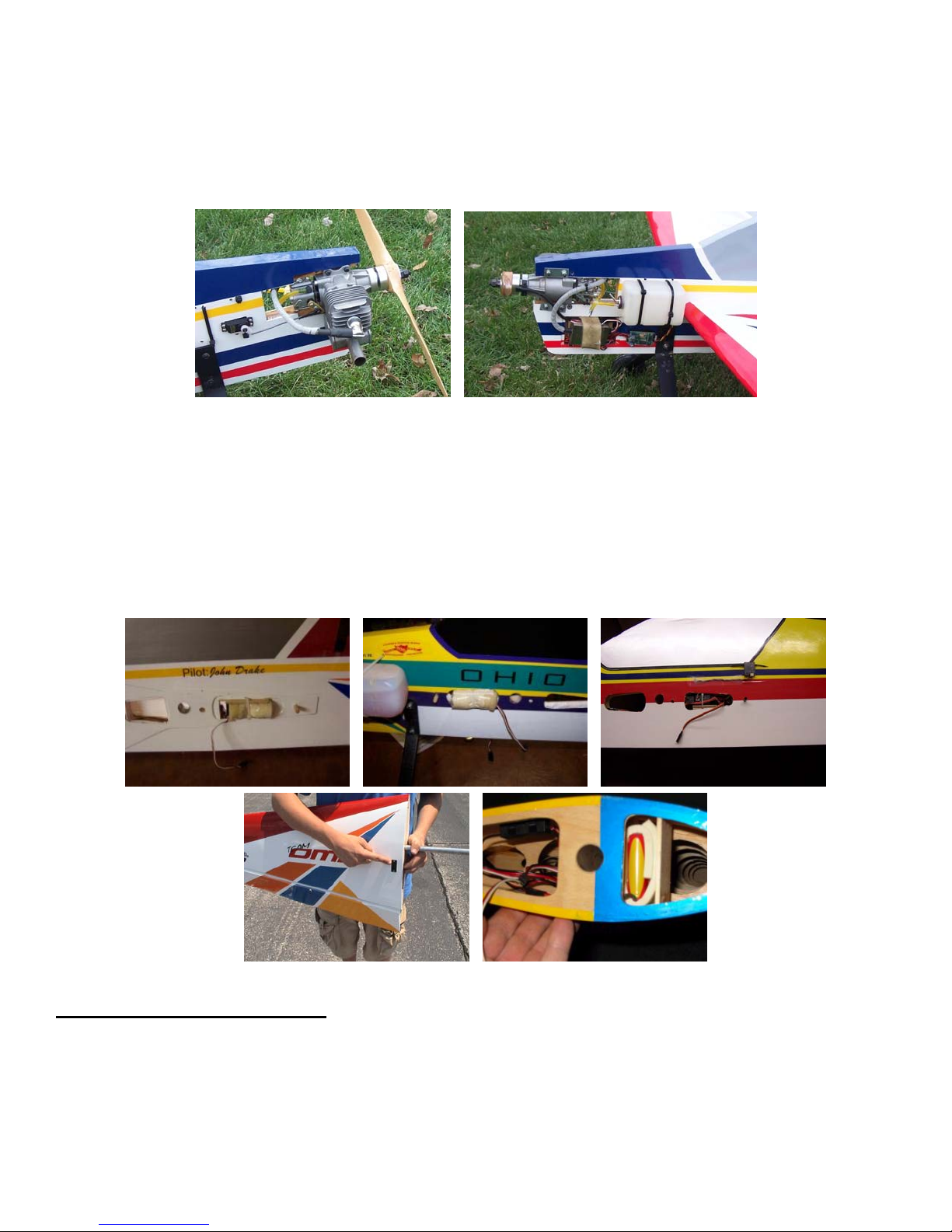
accurate measurement. Once you have determined the engine placement, drill the holes and mount your
engine using the supplied bolts, washers, and locking nuts. Use thin CA on the inside of the holes to harden
them up. You may wish to add about 2-3 degrees of right thrust by adding washers or wedge plates under
the engine before mounting. Finally complete the throttle pushrod using the supplied 2 mm pushrod and
clevis. Make sure you have the proper throws set for idle and full. Install your muffler, prop and spinner.
7. The preferred location for the receiver is either in the forward or aft fuselage opening between the wing
panels. One way to accomplish this is by gluing a flat piece of lite-ply on the top surface of the opening and
securing the receiver with tie straps or Velcro. The switch can be mounted in the hatch cover, anywhere
under the fuselage sheeting, or in the wing next to the battery (preferred location). If mounting in the left
wing panel a good trick to do is to use a Y-harness to connect the left aileron servo to the output of the
switch. When installing the wing you simply plug the end of the Y-harness into the aileron channel of the
receiver. With this configuration the rx battery would be installed in the leading edge area of the left wing.
Spektrum rx shown here
Good switch location
ELECTRIC MOTOR VERSION:
1. Locate the supplied electric motor mount backing plates. They are two plywood pieces that look like an
“H”. Glue the two pieces together making sure that they are perfectly aligned with each other. Once dry,
trial fit the mount in place on the fuselage. Start at the front of the fuselage engine area and slip the mount
all the way to the back of the motor mount area. Once satisfied with the fit, mark and trim away any
covering under the mount and then glue in place with epoxy. Use a square to make sure the motor mount is
on straight with no up, down or offset built into it. Once the glue is dry, either put wood screws that are
Page 12
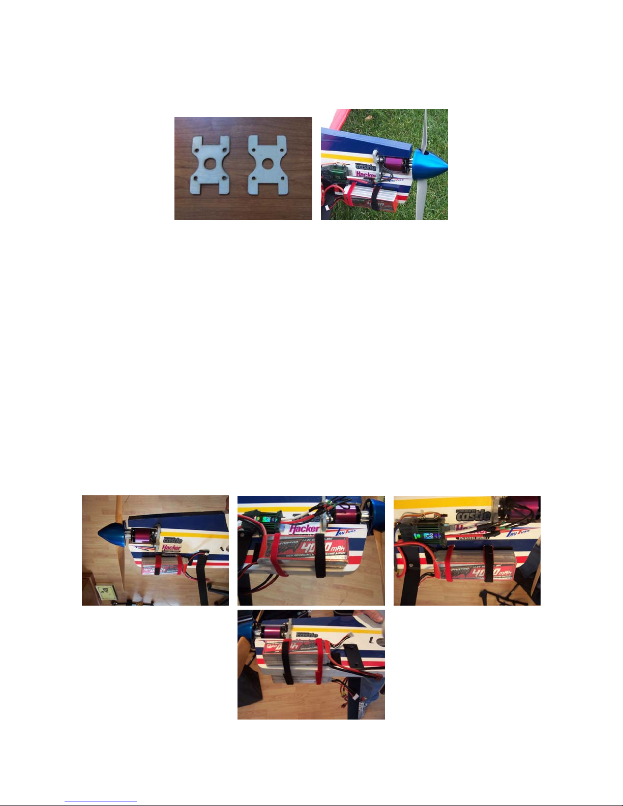
counter sunk through the mount and into the hardwood behind the mount or drill and use dowels to help
secure the mount to the plane. When you mount the motor, you can use washers to give a 2-3 degrees of
right off set if desired.
Now you have to make a decision as to how you are going to power the flight pack. If you are going to us
2. e a
separate battery for the flight pack, install it in the battery hatch in the nose and follow the same steps to
feed the battery lead back to receiver as the gas version. If you are going to u
se the BEC in the ESC to
power the flight pack, then you will need to glue the battery hatch in place.
3.
Before you glue the battery hatch in place, with a sharp Exacto knife cut a slit in the front and rear upper
corners of the hatch cavity and then notch the hatch cover in the same location. Make these slits about a ½
”
wide and 1/8” deep. These slots are where you will install your Velcro straps to secure the lipo batteries.
4.
On both sides of the fuselage below the motor mount area, carefully cut out the covering from in front of the
main landing gear up to about 1” from the nose of the plane. This is where the Velcro strips will be glued in
place on the side of the fuselage to mount the lipo batteries. Make the Velcro strip the width of the batteries
so they don’t rock on the plane. Remove the covering slightly smaller than the Velcro strips and then glue
the strips in place on the side of the fuselage. Slip ½” Velcro strips in the slots made in the battery ha
and wrap around the bottom of the fuselage. Allow enough length to cover two 4 cell lipo batteries.
tch
Page 13
5. Mount the wings and install the lipo batteries under the motor. You can mount the ESC on either side of the
fuselage in the available space behind the motor. Once you have found a location, drill holes through the
fuselage for zip ties to secure the ESC. Use a Velcro strip to mount the ESC and the zip ties to secure it.
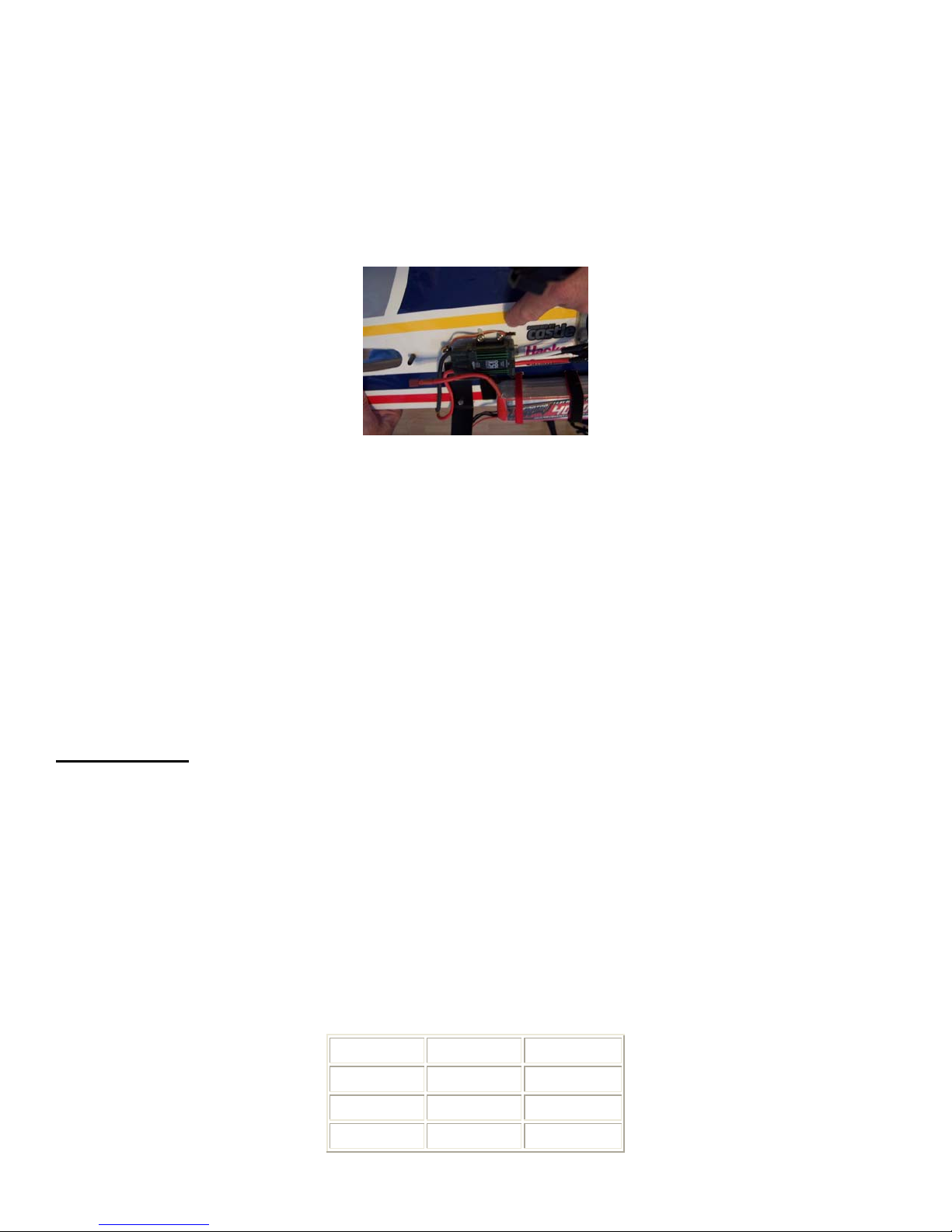
6. Locate the tunnel in the nose and cut a small opening that the connector on the ESC can pass through. The
picture below shows the ESC and hole on the left side of the fuselage. Put an extension of the ESC power
lead and run through the tunnel to the receiver area.
7. The lipo batteries can be moved front and aft along the Velcro strips to achieve the balance desired. The
electric version balances in the same place as the gas version,
8. OMP has done a lot testing to the electric set up on the Fusion and recommends the Hacker A50-14L with a
100 AMP ESC and an APC 18X8 prop. We also recommend using two 4 cell 4000 mah capacity lipo
batteries connected in series with a Y-harness to produce an 8-cell lipo power. With this system you will
achieve 2100 watts and the Fusion will have more than enough power for any 3D maneuver you can think
of with power to spare. Any motor, ESC, and battery combination that will produce in this power range will
work fine for this plane.
RADIO SETUP:
This aircraft is extremely aerobatic! The Fusion was designed to fly pattern and IMAC style maneuvers as
well as 3D extremely well. If you are not used to flying an extremely responsive aircraft you should set the
initial throws to under 30 degrees of movement for the elevator and rudder and about 25 degrees for the
ailerons. This represents a good setting for getting started. More experienced pilots will want to set the throws
to as much as 45 degrees or more for high rates on the tail surfaces. The air foiled ailerons are very effective
and thus 30-35 degrees or so deflection is adequate here. The use of dual rates and exponential is highly
recommended for most pilots. For flying precision aerobatics, it is important to have the proper amount of
throws for each type of maneuver. Many experienced pilots will set different mode switches or rate switches
accordingly. For example there may be a mode just for doing snaps while another mode may be used for
performing spins. We have found that the following settings provide a good initial setup for pattern and 3d
work. Use the low rates for pattern and the high rates for 3D. Always check the functions, range, and proper
directions of your radio setup prior to flying.
Low Rate High Rate
Elevator 12 degrees 45 degrees
Rudder 25 degrees 45 degrees
Ailerons 25 degrees 35 degrees
Page 14
BALANCING:
Most state of the art aerobatic aircraft allow for a wide margin for balancing depending on what level of
precision or freestyle the pilot prefers. To perform properly without being too squirrelly, you must not go too
aft on the CG. OMP recommends an initial CG setting of 8.3 - 8.9 inches behind the leading edge of the
wing at the root. More experienced pilots may want to set the CG further aft. Varying weights of engines and
radio gear will dictate how you should install each. The engine can be moved forward or aft on the engine
mount to shift weight. Also the battery and receiver can be located in any of three hatch locations in the
fuselage. The battery can also be mounted in the left wing along with the switch and a "Y-harness" to the left
aileron servo. These options should allow you to balance the model without adding any weight.
Note: The best way to check your balance is to trim for level flight in the air and then roll inverted. The
aircraft should maintain level flight with very little to no down elevator. If the aircraft climbs when inverted
then you’ve probably got your CG too far aft.
Again, thank you for purchasing the OMP Fusion Profile. If you have any comments or questions about this
manual or the aircraft please email “[email protected]”.
OHIO MODEL PRODUCTS
199 Stratford Lane
Xenia, Ohio 45385
(937) 372-0603
www.ohiomodelplanes.com
 Loading...