

OmniTurn GT-75 Service Manual

Safety Warnings
Read and heed all “DANGER “ and “CAUTION” labels on the machine.
MOVING PARTS CAN CAUSE INJURIES! Keep hands and clothing
clear of spindle and tooling plate at all times.
DO NOT OPERATE WITH DOOR or SPLASH SHIELD OPEN!
DO NOT OPEN DOOR DURING OPERATION!
DO NOT operate machine without guards, doors and covers in place.
DO NOT operated while under the influence of alcohol or drugs,
including prescription drugs.
DO NOT wear loose clothing while operating machine.
DO NOT wear jewelry (necklaces, bracelets, watches, rings) while
operating machine.
!
Keep long hair tied up and out of the way.
Wear eye and face protection.
Report any malfunction to your supervisor.
1.1

OmniTurn GT-75 Major Components
CNC Control
Spindle Motor
Collet Actuator
Air Lube for Actuator
(hidden)
Palm Box
(Two-hand Cycle-Start &
Manual Collet open/close)
Tooling
Plate
X-Axis
Motor
Sliding Door
(Interlocked)
Collet Closer Air
Pressure
Air Pack
Main Air
Regulator/
Filter
Spindle Drive
Cabinet
Leveling
Mounts
Chip Pan
Coolant Pump
Coolant Tank
(Door removed for clarity)
Door Interlocks
Opening the sliding door will put machine into E-Stop, same as Palm Box E-Stop.
If this door is opened before pressing Cycle Start, program will not start: Main
OmniTurn Menu will appear. Secure door, select Automatic Mode then press
Cycle Start.
If door is opened while program is running, all motion will stop and Main
OmniTurn Menu will appear. Secure door, select Jog Mode then send slide Home
(H,Z,X) before re-starting program.
If door is opened during threading cycle, all motion will stop as above, but
CNC Control must be shut off, then on to re-boot.
1.2
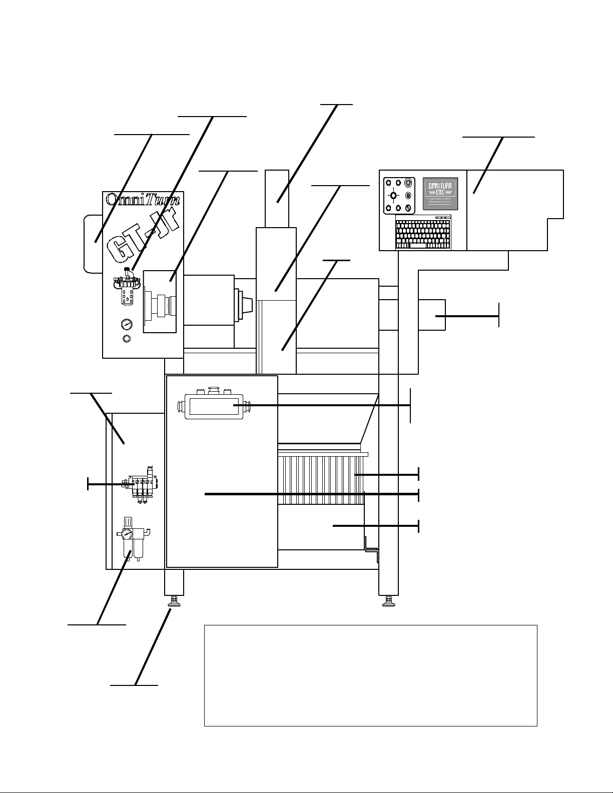
OmniTurn GT-Jr Major Components
Collet Closer
Air Pressure
& Air Lube
for Actuator
X-Axis
Motor
Spindle Motor
Spindle Drive
Cabinet
Hatch
(Interlocked)
CNC Control
Splash
Guard
(Interlocked)
Tooling
Plate
Z-Axis
Motor
Palm Box
(Two-hand Cycle-Start &
Manual Collet open/close)
Air Pack
Main Air
Regulator/
Filter
Leveling
Mounts
Chip Pan
Coolant Pump (hidden)
Coolant Tank
(Door removed for clarity)
Door Interlocks
Lifting the splash guard or opening the hatch will put GT-Jr into E-Stop, same as
Palm Box E-Stop. If these are opened before pressing Cycle Start, program will
not start: Main OmniTurn Menu will appear. Secure hatch or splash guard, select
Automatic Mode then press Cycle Start.
If guard or hatch is opened while program is running, all motion will stop and
Main OmniTurn Menu will appear. Secure guard or hatch, select Jog Mode then
send slide Home (H,Z,X) before re-starting program.
If guard or hatch is opened during threading cycle, all motion will stop as
above, but CNC Control must be shut off, then on to re-boot.
1.3
OmniTurn
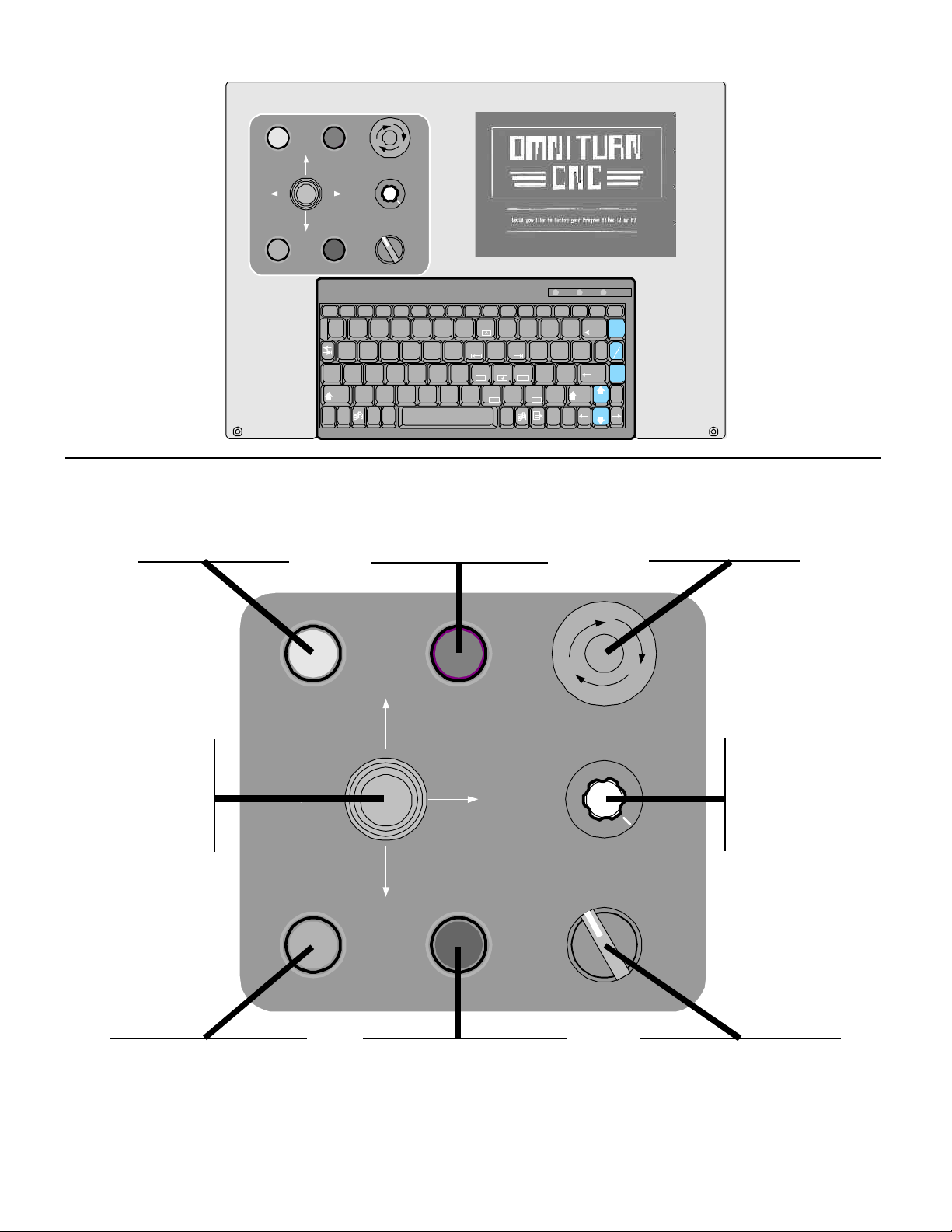
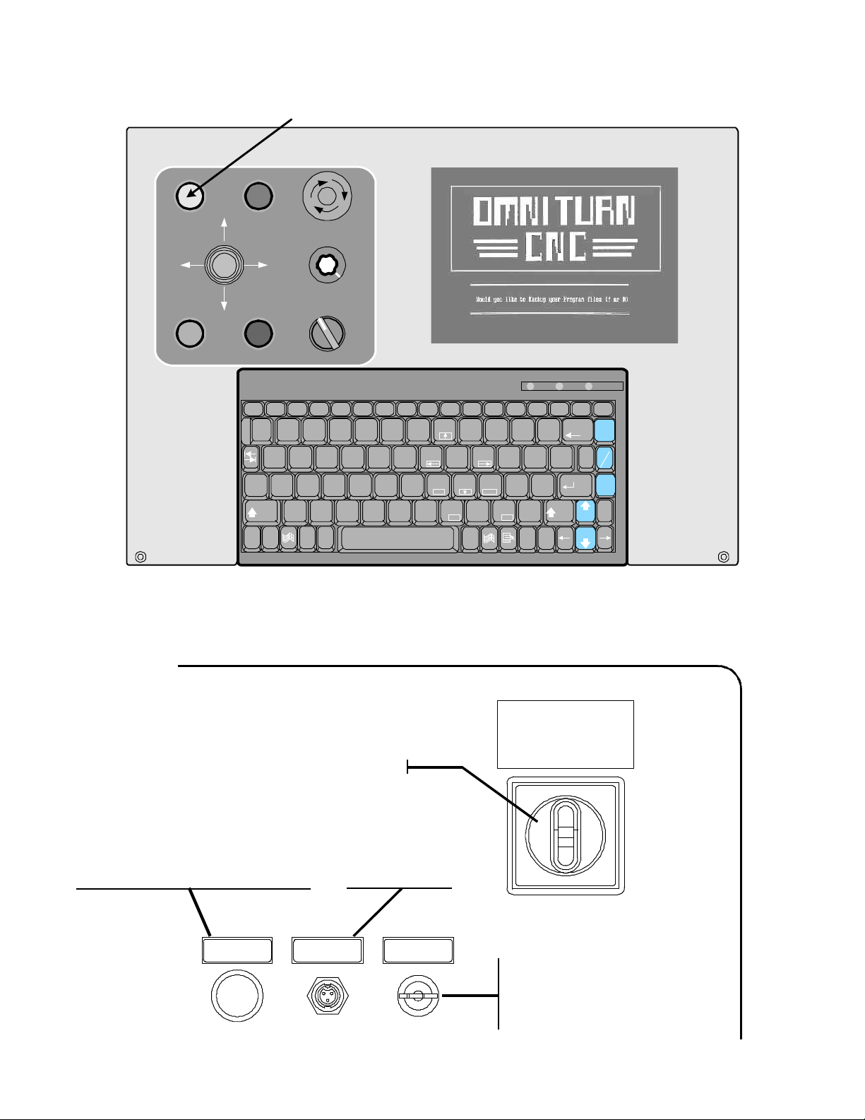
OmniTurn Front Panel: Knobs & Switches
CONTROL
ON
JOG JOG
CYCLE
START
Sets Control ON or OFF.
Illuminates with power ON.
Press ON/Press OFF
SERVOS
ON
Z +Z -
!1@2#
Q W
A
Z
Shift
EMERGENCY
SPINDLE
OVERRIDE
SPINDLE
3
Alt
STOP
1000
OFFAUTO
*8&7^6%5$
(9)
GFDS
Home PgUp
H
MNBVCX
KJ
Ins
4
~
`
X -
X +
MOTION
STOP
Esc F1 F10F9F8F7F6F5F4F3F2 F11 F12
Caps
Lock
Ctrl Fn
Sets Servos ON when
Control is ready. Illuminates when Servos are
ON. Momentary action
Caps
Num
Lock
Num
Lock
0
{
P
OIUYTRE
[
PgUpEnd
?/>
<
.
,
Del
Alt
Ins
Scroll
Lock
Lock
PrtSc
Scroll
Pause
SysRq
Lock
Break
Spindle
+=_
Backspace
100%
|
}
\
]
Coolant
"':;L
Parts
Enter
Catcher
End
Shift
Spindle
Spindle
Del
Halts all machine
movement and resets
all M-Functions.
Press ON/Twist OFF
Manually move the
slide when in Jog
Mode. Continuous
or incremental
according to key-
board selection.
Starts program in Auto
Mode. Executes command
in MDI Mode. Illuminates
while program is running.
CONTROL
ON
JOG JOG
CYCLE
START
SERVOS
ON
X -
Z +Z -
X +
MOTION
STOP
Stops slide movement during
program. Illuminates when
active. Press Cycle Start to
continue or Esc Key to stop
program.
EMERGENCY
STOP
SPINDLE
OVERRIDE
SPINDLE
Adjusts speed of
spindle. (Not
effective for C-Axis
machines). Spindle
1000
OFFAUTO
will not run when
this is full CCW.
Manually set spindle OFF
and ON as required during
setup. Lever action.
1.4
OmniTurn
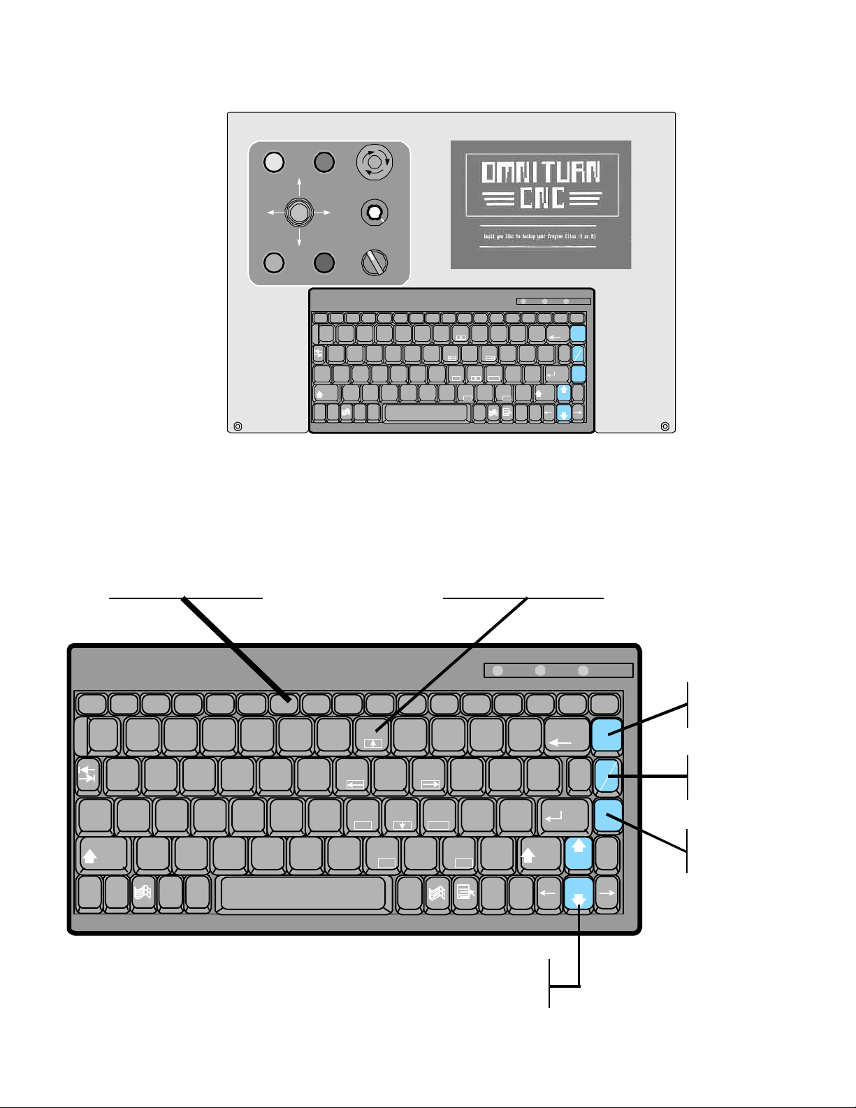
OmniTurn Front Panel: Keyboard
Function Keys set Feed
Rate Override while
running program.
Special functions are
described on page 5.3.
CONTROL
ON
JOG JOG
CYCLE
START
SERVOS
ON
Z +Z -
STOP
!1@2#
Q W
A
Shift
Z
EMERGENCY
STOP
SPINDLE
OVERRIDE
SPINDLE
3
Alt
1000
OFFAUTO
*8&7^6%5$
GFDS
Home PgUp
H
MNBVCX
KJ
Ins
4
~
`
X -
X +
MOTION
Esc F1 F10F9F8F7F6F5F4F3F2 F11 F12
Caps
Lock
Ctrl Fn
Number Keys set Jog
speed and Jog increment in Jog Mode.
Functions are described
starting on page 1.9.
(9)
OIUYTRE
<
,
Alt
Caps
Num
Lock
Num
Lock
0
{
P
[
PgUpEnd
?/>
.
Del
Ins
Scroll
Lock
Lock
PrtSc
Scroll
Pause
SysRq
Lock
Break
Spindle
+=_
Backspace
100%
|
}
\
]
Coolant
"':;L
Parts
Enter
Catcher
End
Shift
Spindle
Spindle
Del
Esc F1 F10F9F8F7F6F5F4F3F2 F11 F12
Caps
Lock
Ctrl
!
1@2
Q W
A
Shift
Fn
#
$
3
4
^
%
6
5
GFDS
Z
~
Alt
`
*
&
Home PgUp
8
7
H
KJ
End
MNBVCX
Ins
(
9
)
0
P
OIUYTRE
:
L
PgUp
<
,
;
>
.
Del
Alt
Increase or Decrease spindle
speed. Effective for C-Axis
and standard spindles.
1.5
Num
Lock
Num
Lock
_
{
[
?
/
Ins
Caps
Scroll
Lock
PrtSc
SysRq
+
Backspace
=
}
]
"
'
Scroll
Lock
Enter
|
\
Lock
Pause
Break
Spindle
100%
Coolant
Parts
Catcher
Set spindle
speed to 100%.
(PgUp)
Set coolant
ON/OFF
(PgDn)
Set M25/M26
Del
Shift
Spindle
Spindle
End
or Parts
Catcher out/in
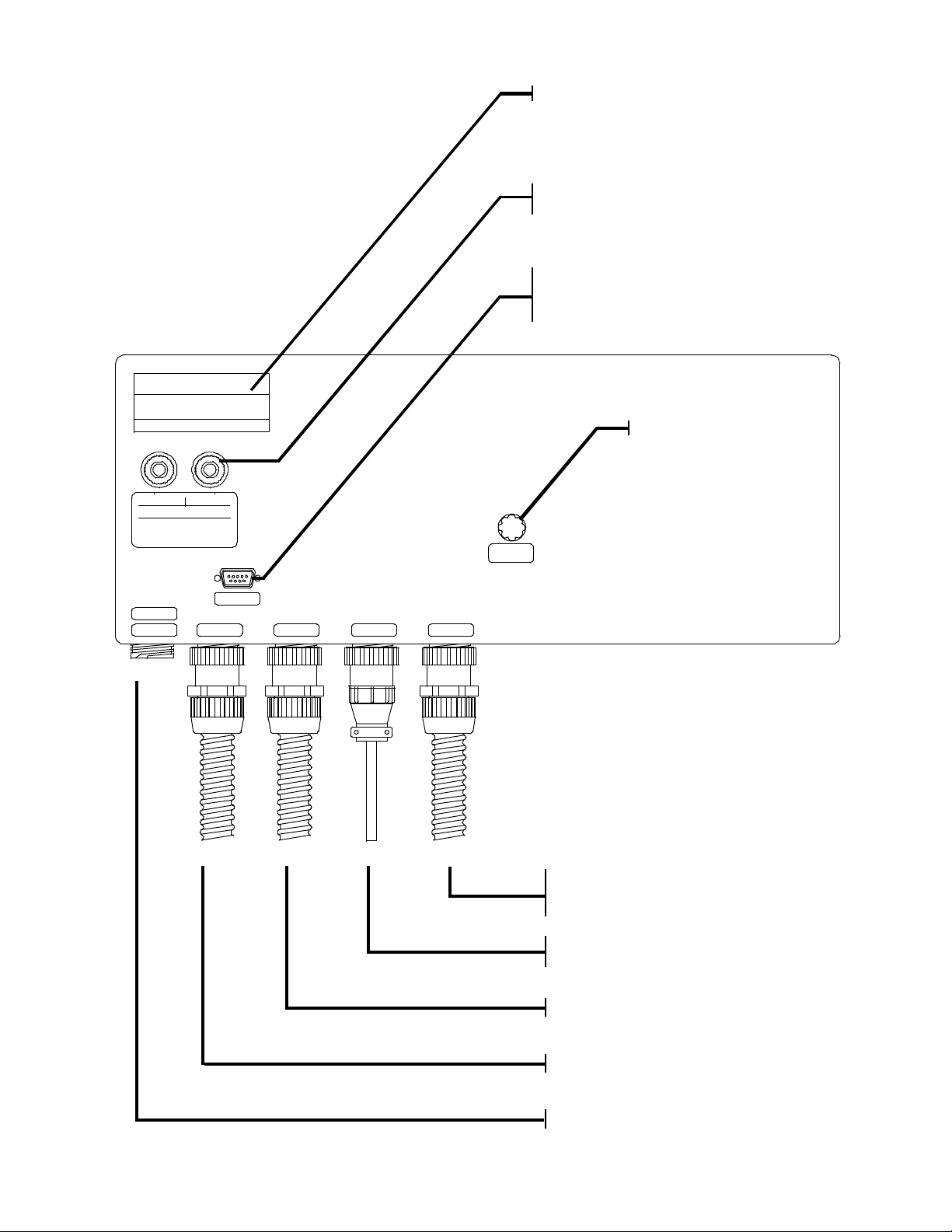
OmniTurn Rear Panel
Serial Number Label
Servo overloads.
Press to reset.
RS-232 Port
For transfering files. Also
used with C-Axis option.
OMNITURN
X Axis Z Axis
Servo Error due to Overload
If the breaker has not tripped,
the servo-amp may have.
To reset amp,wait one minute
with servos off, then set servos on.
PLC
C AXIS
CNC Attachments
X AXIS
RS 232
CNC Control Main Fuse
(10A)
F1
SPINDLEZ AXIS
Z AXISX AXIS
SPINDLE
MISC
MISC
Miscellaneous Cable:
Carries signals to and from Spindle
Cabinet.
Spindle Encoder:
Enables threading and IPR feeds.
Z-Axis Motor-Tach-Encoder
X-Axis Motor-Tach-Encoder
Optional C-Axis or PLC Connector
1.6
Start - Up: Apply Power
After the OmniTum has been installed and all of the cables are connected set 220vac disconnect ON.
The 220vac disconnect is located on the Spindle Drive Cabinet at left-hand side of the GT-75 or GT-Jr, as
illustrated below.
Turn CNC ON here AFTER setting 220vac disconnect ON
CONTROL
ON
JOG JOG
CYCLE
START
SERVOS
ON
X -
X +
MOTION
STOP
Esc F1 F10F9F8F7F6F5F4F3F2 F11 F12
!1@2#
Caps
Lock
Shift
Ctrl
Z +Z -
Q W
A
Fn
Z
EMERGENCY
STOP
SPINDLE
OVERRIDE
SPINDLE
3
Alt
1000
OFFAUTO
%
$
4
~
`
6
5
GFDS
*8&7^
Home PgUp
H
End
MNBVCX
Ins
(9)
KJ
Alt
Omni
0
P
OIUYTRE
L
PgUp
<
>
.
,
Del
Turn
Num
Caps
Scroll
Lock
Lock
Num
Lock
SysRq
+
_
=
{
[
"':
;
?
/
Del
Ins
PrtSc
}
]
Backspace
Shift
Scroll
Lock
Enter
Spindle
Spindle
Lock
Pause
Break
Spindle
100%
|
\
Coolant
Parts
Catcher
End
OmniTurn front panel Keyboard
After boot-up, the first screen you see will ask you to back-up your program files. Always select “Y” to
backup. Only those programs which have been edited will be copied to the floppy disk at rear of machine
Spindle Drive Cabinet
220 VOLTS
Main Power Disconnect
ON
I
Spindle Fault Switch
This Push-Button will light with spindle
drive fault, if interlock is opened, or if
machine is in Palm-Box E-Stop. Reset
is effective only with fault.
SPINDLE FAULT
Press to Reset
TripleAir Barfeed
EoB Connector
Barfeed EoB
Connect TripleAir
barfeed EofB here
Puts OmniTurn in
Palm-Box E-Stop.
Interlock
Override Switch
OFF
O
Interlock Bypass Key-Switch
To Jog, or operate the machine with
splash-guard or hatch open, this
switch must have key turned CW. Key
should be under supervisor’s control
1.7
Start - Up: Turn on Servos
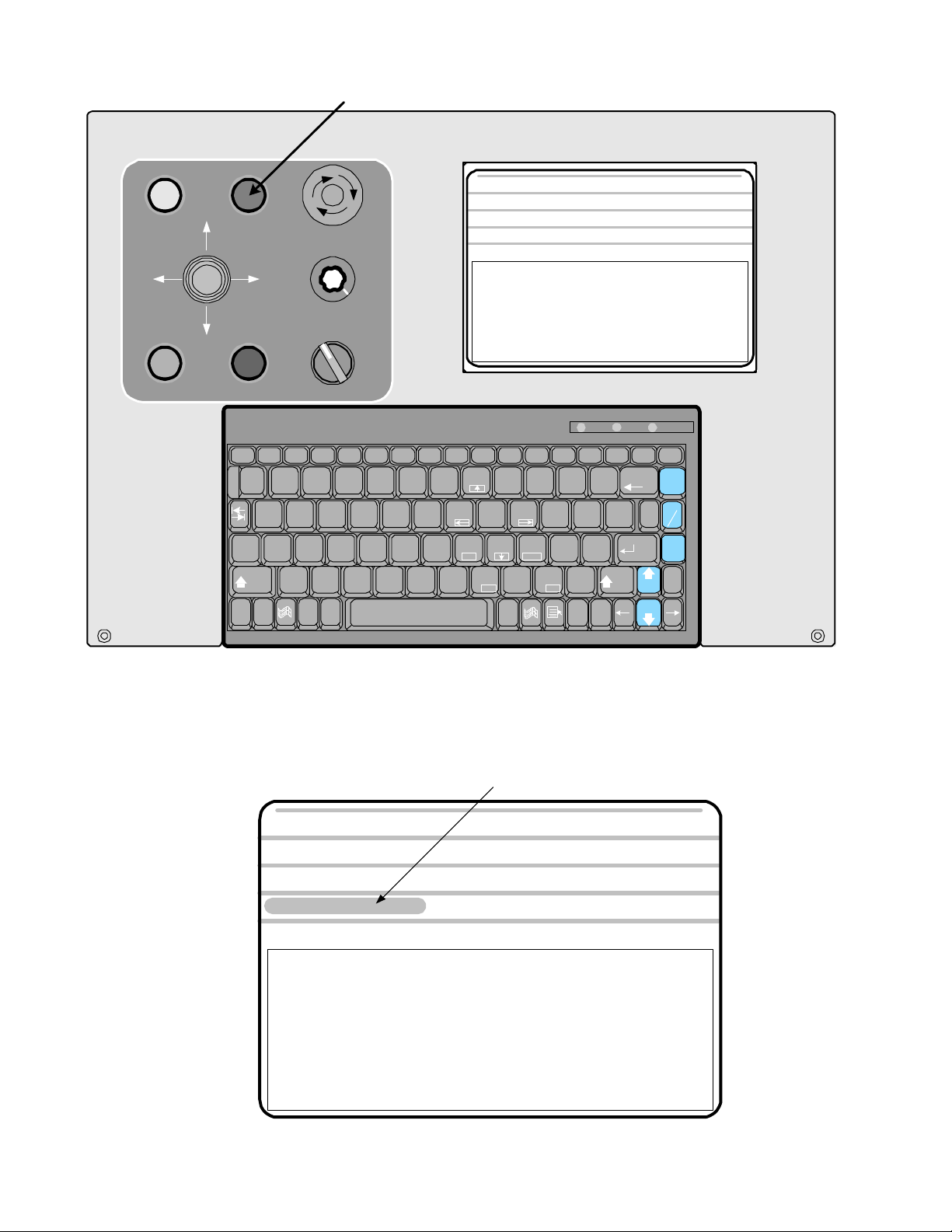
After the programs have been backed up you will be prompted to turn the servos on.
Turn servos ON with Blue button
CONTROL
ON
JOG JOG
CYCLE
START
POSITION
COMMAND
SERVOS
ON
X -
Z +Z -
X +
MOTION
STOP
Esc F1 F10F9F8F7F6F5F4F3F2 F11 F12
!1@2#
Q W
Caps
Lock
Shift
Ctrl
Fn
EMERGENCY
STOP
1000
SPINDLE
OVERRIDE
OFFAUTO
SPINDLE
^
%
$
3
4
A
Z
~
Alt
`
6
5
GFDS
PLEASE TURN SERVOS ON
Jog Automatic Single Block
Jog mode allows manual motion, tool offsets, and zero
Single Block and Automatic allow execution of stored programs,
and also give access to tool offsets and the Editor
Manual Data Input allows immediate execution of program
statements, as well as tool offset and editing functions
*
&
Home PgUp
7
H
(
8
9)0
KJ
End
MNBVCX
Alt
Omni
: X +0.00000 Z +0.00000 FEED 10.0 IPM
P
OIUYTRE
L
PgUp
<
>
,
.
DelIns
_
{
[
:
;
?
/
Ins
Turn
Caps
Num
Lock
Lock
Num
PrtSc
Lock
SysRq
+
Backspace
=
}
]
"
'
Shift
Del
Scroll
Lock
Enter
Spindle
Spindle
Scroll
Lock
|
\
PERCENT FEED: 100
Manual Data Input
Pause
Break
Spindle
100%
Coolant
Parts
Catcher
End
OmniTurn front panel Keyboard
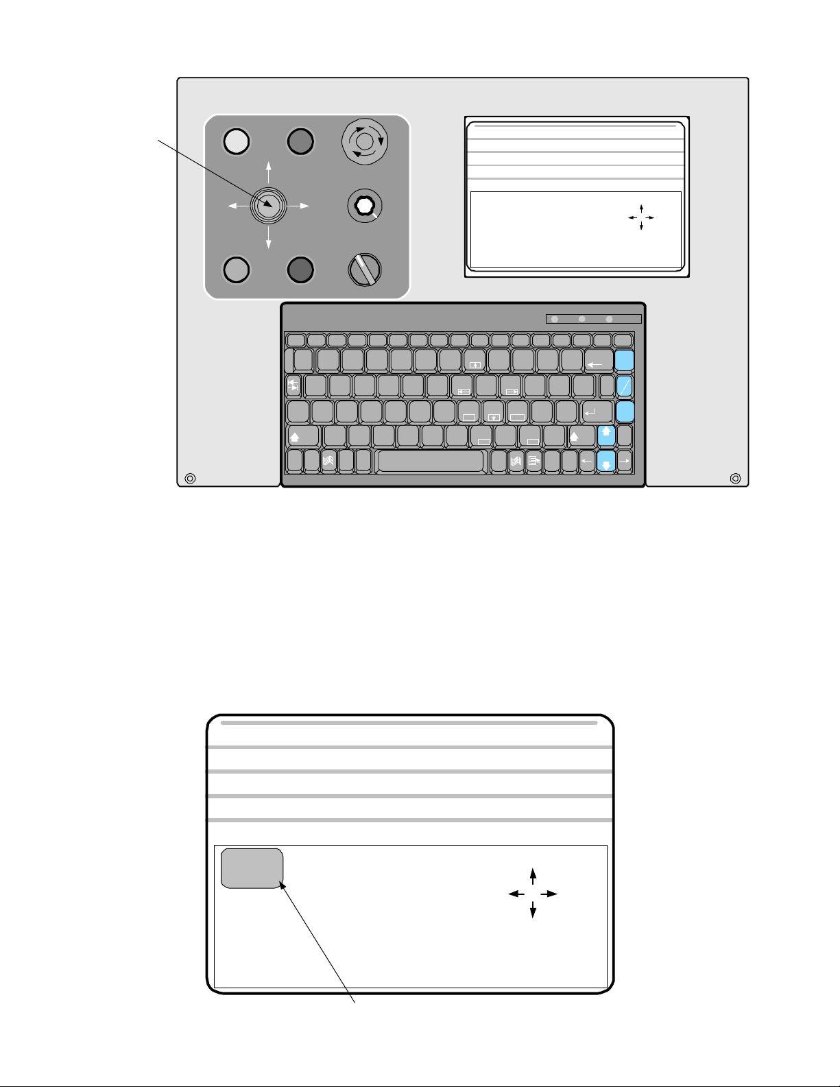
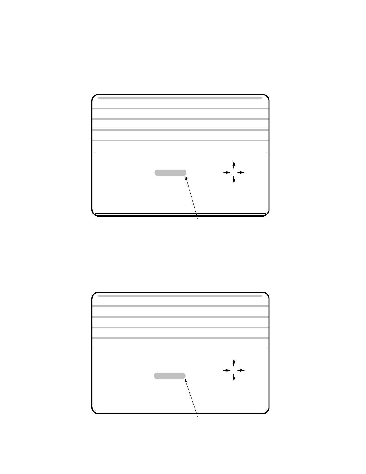
Press the blue “Servos On” pushbutton. It should illuminate and you should hear a slight hum as the axes
motors engage. This part of the screen is the prompt area, and different information will be presented here
according to the current mode or page.
The prompt area requests "Servos on."
POSITION
COMMAND
PLEASE TURN SERVOS ON
Jog Automatic Single Block
Jog mode allows manual motion, tool offsets, and zero
Single Block and Automatic allow execution of stored programs,
and also give access to tool offsets and the Editor
Manual Data Input allows immediate execution of program
statements, as well as tool offset and editing functions
: X +0.00000 Z +0.00000 FEED 10.0 IPM
PERCENT FEED: 100
Manual Data Input
1.8
Start - Up: Establish Home
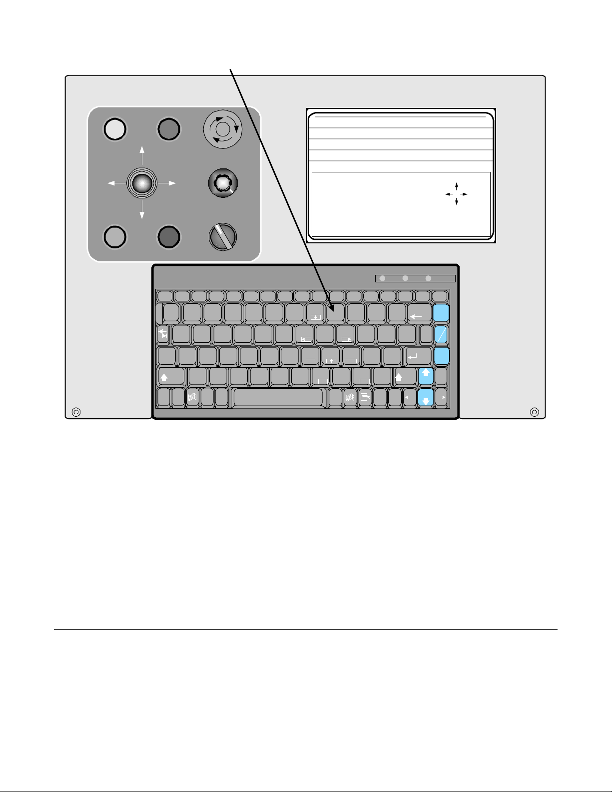
Press "9" key to establish Home
CONTROL
ON
JOG JOG
CYCLE
START
POSITION
COMMAND
SERVOS
ON
X -
Z +Z -
X +
MOTION
STOP
Esc F1 F10F9F8F7F6F5F4F3F2 F11 F12
!1@2#
Q W
Caps
Lock
Shift
Ctrl
Fn
EMERGENCY
STOP
1000
SPINDLE
OVERRIDE
OFFAUTO
SPINDLE
^
%
$
3
4
A
Z
~
Alt
`
6
5
GFDS
HOME MUST BE ESTABLISHED
Jog Automatic Single Block
1. Slow
2. Medium
3. Fast
4. .00005
5. .0010
6. .0100
PRESS 'ESC TO RETURN TO MENU
*
&
Home PgUp
8
7
End
KJ
MNBVCX
H
(
9
Alt
Omni
: X +0.12635 Z -0.10475
:
7. .1000
8. 1.0000
9. Est Home
S. Set Zero
H. Go Home
T. Set Tool
)
_
0
-
P
OIUYTRE
L
PgUp
<
,
{[
:
;
?
>
/
.
DelIns
Ins
Turn
Caps
Num
Lock
Lock
Num
PrtSc
Lock
SysRq
+
Backspace
=
}]
"
'
Shift
Del
Scroll
Lock
Ente
r
Spindle
Spindle
Scroll
Lock
|
\
FEED 10.0 IPM
PERCENT FEED: 100
Manual Data Input
- X
- Z
+X
Pause
Break
Spindle
100%
Coolant
Parts
Catcher
End
+Z
OmniTurn front panel Keyboard
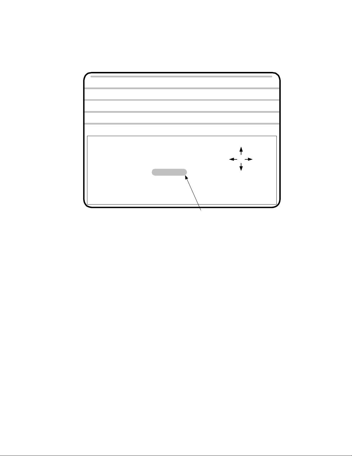
Establish “Home”
After the servos are turned on, the control automatically goes to the JOG mode. This is done so that
machine “HOME” can be established. The control will not allow you to leave the JOG mode until the
homing procedure has been completed.
Press “2” (Medium Jog) or “3” (Fast Jog) on the Keyboard, and use the Jog Stick to move slide to within
0.200” from Zero in X and Z as illustrated on the next page. Press “9” on the Keyboard, then press Cycle
Start to start the homing procedure. The slide will move slowly in +Z, then in -X, seeking the home marks
on the motor encoders. When homing is complete, X & Z position indicators will read 0.00000.
The following three pages describe the homing procedure in detail.
Power Down Procedure
It is a good practice, but not necessary, to press the E-Stop before turning the control off. To turn the
control off, press the amber Control ON button. Then set the spindle drive disconnect to OFF.
1.9
Establish Home: Detail
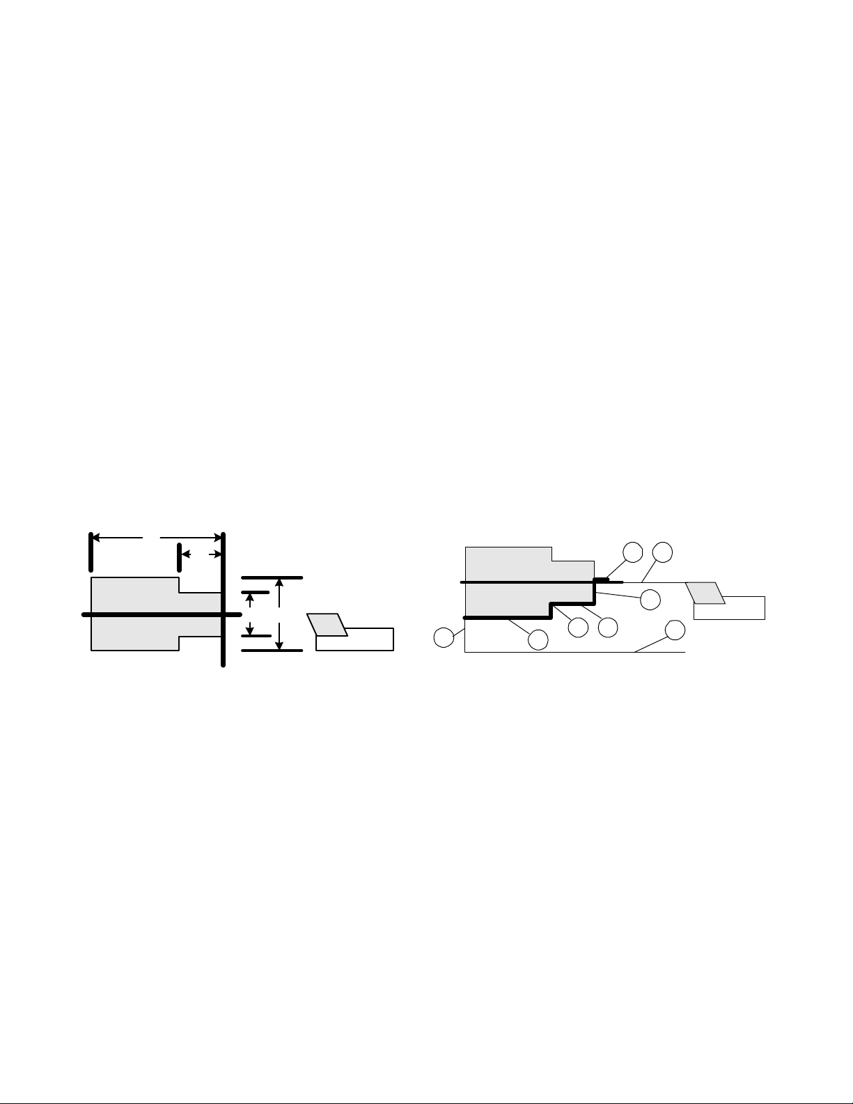
Press “2” (Medium Jog) or “3” (Fast Jog) on the Keyboard, and use the Jog Stick to move
slide to within 0.200” from Zero in X and Z as illustrated below. The X axis should be on
the plus side of zero, and the Z axis should be on the minus side.
If you are too far away from zero you will be off by .200” when the Ref Zero is found
because the axis has a “home” every revolution.
Too far away to start Ref Zero
0
0
1 2 3 4 5 6 7 8 9
Within .2" of 0; this is close
enough to begin Ref Zero
0
10
When the slide has been jogged to within 0.200” of zero for both axes, press the ”9” key
on the keyboard, then press Cycle Start pushbutton to complete the homing sequence.
The control will first move the Z and then X axis.
After the procedure, check that the location for zero is where you want it. If you have
missed the zero, press the “2” key (Med Jog) then jog the slide to the correct location, then
press “9” then Cycle Start again.
Verify that the position display at the top of the screen now reads zero for both axes.
1 0
See following page for the screens which display the process.
1.10

Establish Home: Screens
POSITION
COMMAND : X-40
MAKE JOG SELECTION
Jog Automatic Single Block
1. Slow
2. Medium
3. Fast
4. .00005
5. .0010
6. .0100
PRESS 'ESC TO RETURN TO MENU
: X +0.15095 Z -0.15860 FEED 10.0 IPM
7. .1000
8. 1.0000
9. Est Home
S. Set Zero
H. Go Home
T. Set Tool
PERCENT FEED: 100
Manual Data Input
- X
- Z
Press 9 when BOTH axes are
within 0.200" of Home.
+Z
+X
POSITION
COMMAND : X-40
PRESS CYCLE START TO ESTABLISH HOME
Jog Automatic Single Block
1. Slow
2. Medium
3. Fast
4. .00005
5. .0010
6. .0100
PRESS 'ESC TO RETURN TO MENU
: X +0.00000 Z +0.00000 FEED 10.0 IPM
PERCENT FEED: 100
Manual Data Input
7. .1000
8. 1.0000
9. Est Home
S. Set Zero
H. Go Home
T. Set Tool
After selecting "Jog 9" (Est Home),
press Cycle Start to complete the
homing sequence.
- Z
- X
+Z
+X
After Home has been established, you can leave the Jog Mode by pressing ”Esc”key
on the keyboard to go to the Main Menu, or you can stay in the Jog Mode and establish the tool offsets. On the following pages the Jog Mode is discussed in detail.
1.11

Establish Home: Explanation
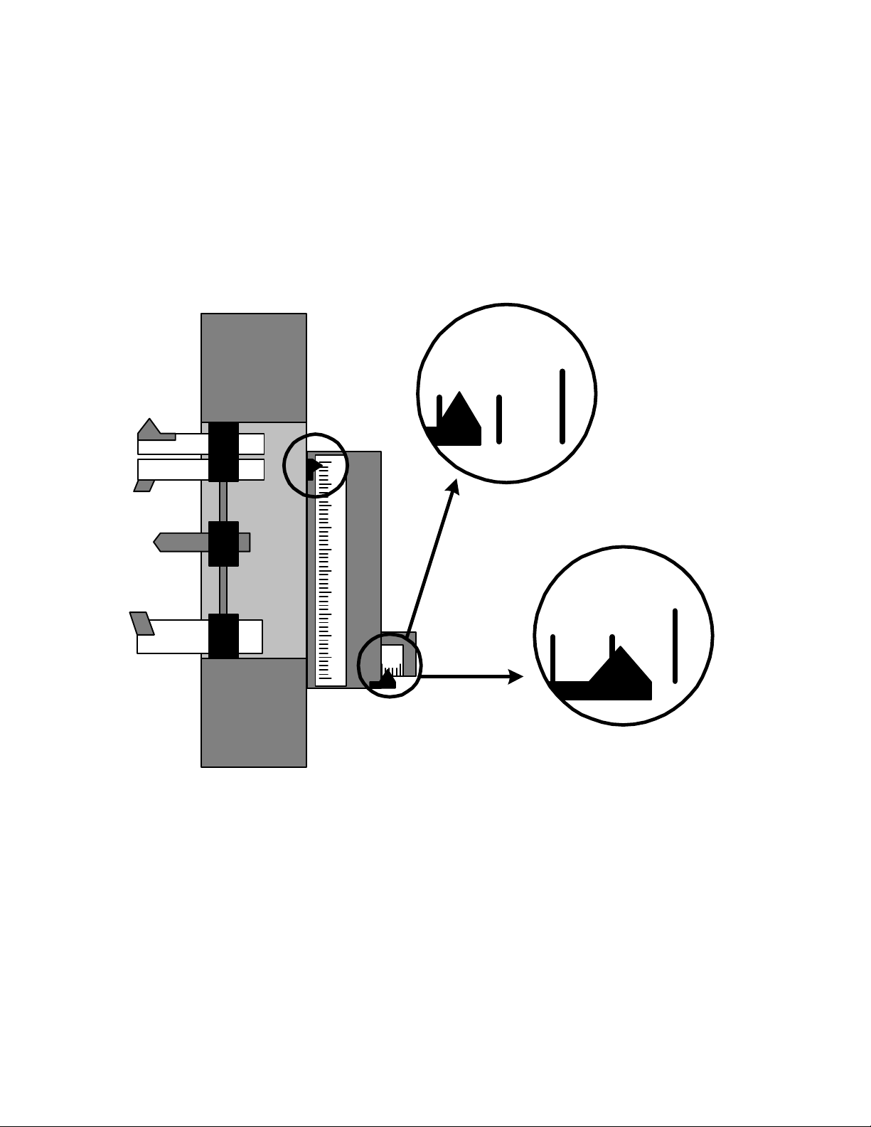
On each axis is a scale that is marked with .2” graduations. These scales are used to establish HOME.
Home is a reference point that can be easily found and repeated. The .2” scales are just an aid to find
this home point.
0
1 2 3 4 5 6 7 8 9
X axis Ref Zero Marker
123 0
10
Z axis Ref Zero Marker
1 marker pulse
1,000 encoder lines
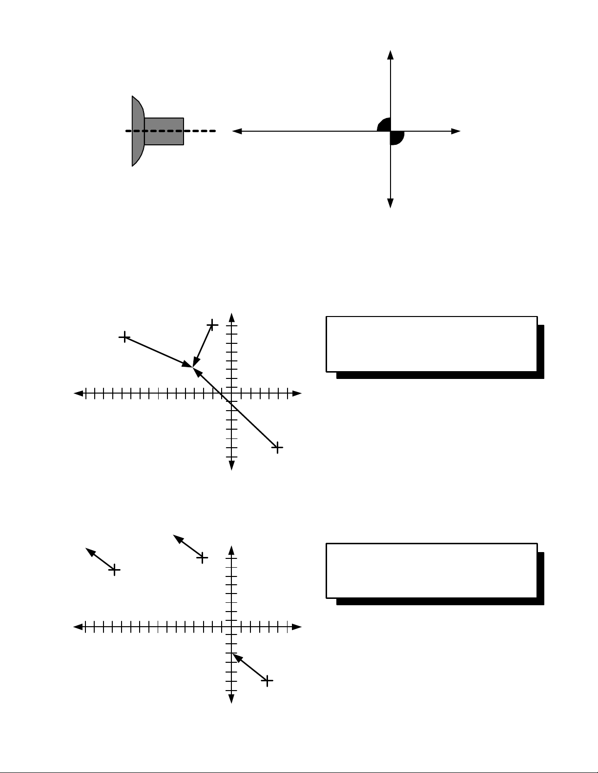
How HOME is established
The HOME location will repeat itself from start-up to start-up within .00005”. So when you start up the
machine from one day to the next it will repeat itself very closely. The point is established by the following:
On the end of the servo motor that drives the axis is an encoder that tells the control how far the slide
has traveled. This encoder follows the slide travel incrementally. The encoder does not know exactly
where the slide is, only how far it has traveled. The encoder works by counting fine lines printed on a disk.
The drawing above is a sketch of this type of rotary encoder. The inside ring of lines is counted to maintain
location. The outside line is used to find a definite location. The encoder will ”see” this line once every
revolution of the ball screw used to position the slide. The ball screw used on the OmniTurn moves the slide
.2” / revolution. So if we position the slide within .2” of what we want to call HOME and then tell the
control to slowly rotate the screw while looking for the single pulse we can establish this as an easily repeatable location. This is how HOME is established.
1.12

Jog
The purpose of the jog mode is to:
• Establish your ”HOME” position. This is always done after starting up the control.
• Set tool offsets
• Move the slide manually
• Bore soft jaws or collets
To enter the jog mode:
If you are just powering up the control it will automatically take you to the jog screen after the servos are
turned on.
If you are at the main menu as shown below, type ”J” .
POSITION
COMMAND
SELECT OPERATION MODE
Jog Automatic Single Block
Jog mode allows manual motion, tool offsets, and zero
Single Block and Automatic allow execution of stored programs,
and also give access to tool offsets and the Editor
Manual Data Input allows immediate execution of program
statements, as well as tool offset and editing functions
: X +0.00000 Z +0.00000 FEED 10.0 IPM
PERCENT FEED: 100
Jog
Ref Zero
Tool Offsets established
Program run
Program Edit
Program Enter
Tool offsets adjustment
Secondary tool offsets
Disk operations
Calcaid programming system
Manual Data Input
Jogging with the Joy Stick
The method for moving the slide is to use the ”Joy stick” actuator on the operators panel. Deflecting this
actuator in the four directions available produces the following motions:
Up X axis minus (away from you on attachment; up on GT-75 & Jr)
Down X axis plus (toward you on attachment; down on GT-75 & Jr)
Left Z axis minus (toward spindle)
Right Z axis plus (away from spindle)
1.13
Jog
Joy stick for
jog operations
CONTROL
ON
JOG JOG
OmniTurn
POSITION
: X +0.00000 Z +0.00000 FEED 10.0 IPM
COMMAND
SERVOS
ON
X -
X +
EMERGENCY
STOP
Z +Z -
1000
SPINDLE
OVERRIDE
OFFAUTO
MAKE JOG SELECTION
Jog Automatic Single Block
1. Slow
2. Medium
3. Fast
4. .00005
5. .0010
6. .0100
PRESS 'ESC TO RETURN TO MENU
7. .1000
8. 1.0000
9. Est Home
S. Set Zero
H. Go Home
T. Set Tool
PERCENT FEED: 100
Manual Data Input
- X
- Z
+Z
+X
CYCLE
START
MOTION
STOP
Esc F1 F10F9F8F7F6F5F4F3F2 F11 F12
!1@2#
Q W
Caps
Lock
Shift
Ctrl
Fn
SPINDLE
*
6
GFDS
&7^
8
Home PgUp
H
End
MNBVCX
(9)
KJ
<
,
Alt
0
P
OIUYTRE
L
PgUp
DelIns
3
A
Z
Alt
5
4
~
`
%
$
Num
Caps
PrtSc
SysRq
}
]
Lock
Backspace
Shift
Scroll
Lock
Enter
Spindle
Spindle
Scroll
Lock
Pause
Break
Spindle
100%
|
\
Coolant
Parts
Catcher
End
Lock
Num
Lock
+=_
{
[
"':
;
?
/>.
Del
Ins
OmniTurn front panel Keyboard
The speed or increment of the jog mode can be selected. This is done by pressing a number between 1 -8
on the keyboard. The jog speed or increment selected zzzwill change shade. To select a new speed just
select a new number.
Continuous Jog Mode
Deflecting the joystick after selecting 1 -3 will move the slide at a continuous rate:
1. SLOW 1 inch per minute
2. MEDIUM 10 inches per minute
3. FAST 100 inches per minute
POSITION
COMMAND
: X +0.00000 Z +0.00000 FEED 10.0 IPM
PERCENT FEED: 100
MAKE JOG SELECTION
Jog Automatic Single Block Manual Data Input
1. Slow
2. Medium
3. Fast
4. .00005
5. .0010
6. .0100
7. .1000
8. 1.0000
9. Est Home
S. Set Zero
H. Go Home
T. Set Tool
- Z
- X
+Z
+X
PRESS 'ESC TO RETURN TO MENU
Continuous jog selections
1.14

Jog
Incremental Jog Mode
Deflecting the joystick after selecting 4 -8 will move the slide the indicated increment in the direction deflected. Each deflection produces one increment. Holding the joystick in the deflected position will not move
the slide more than one increment. The cycle start light flashes to indicate recognition and then execution of
the increment.
POSITION
COMMAND
MAKE JOG SELECTION
Jog Automatic Single Block
1. Slow
2. Medium
3. Fast
4. .00005
5. .0010
6. .0100
PRESS 'ESC TO RETURN TO MENU
: X +0.00000 Z +0.00000 FEED 10.0 IPM
7. .1000
8. 1.0000
9. Est Home
S. Set Zero
H. Go Home
T. Set Tool
Incremental jog selections
The #9 selection is covered in the Establish Home section
PERCENT FEED: 100
Manual Data Input
- X
- Z
+Z
+X
POSITION
COMMAND
MAKE JOG SELECTION
Jog Automatic Single Block
1. Slow
2. Medium
3. Fast
4. .00005
5. .0010
6. .0100
PRESS 'ESC TO RETURN TO MENU
: X +0.00000 Z +0.00000 FEED 10.0 IPM
7. .1000
8. 1.0000
9. Est Home
S. Set Zero
H. Go Home
T. Set Tool
1.15
PERCENT FEED: 100
Manual Data Input
- X
- Z
Begin finding "HOME"of slide
+Z
+X
Jog
To set a floating zero
Depressing ”S” will cause the present position of the axis to become the zero point. This setting of zero
does not effect the location of the Home. This is a local zero that is used in the manual mode if the
operator cares to use it. When this option is used, the control will prompt you to ”PRESS X TO ZERO
X, Z TO ZERO Z”. You can terminate this procedure at any time by pressing the ”ESC” key.
POSITION
COMMAND
PRESS X TO ZERO X, Z TO ZERO Z
Jog Automatic Single Block Manual Data Input
1. Slow
2. Medium
3. Fast
4. .00005
5. .0010
6. .0100
PRESS 'ESC TO RETURN TO MENU
: X +0.00000 Z +0.00000 FEED 10.0 IPM
PERCENT FEED: 100
7. .1000
8. 1.0000
9. Est Home
S. Set Zero
H. Go Home
T. Set Tool
Set current jposition to Zero
- Z
- X
+Z
+X
To send the slide HOME
Depressing ”H” will bring up the message ”PRESS X TO HOME X, Z TO HOME Z”. It is suggested to
depress Z first, as this will home Z axis and get the tools back out of the way. Then depress X and the slide
will home in the X axis. This function is used to check that the Home you have set is still where you think it
should be. Never use this function until you have first gone through the ”REFERENCE ZERO” procedure
after start-up.
POSITION
COMMAND
PRESS X TO HOME X, Z TO HOME Z
Jog Automatic Single Block Manual Data Input
1. Slow
2. Medium
3. Fast
4. .00005
5. .0010
6. .0100
PRESS 'ESC TO RETURN TO MENU
: X +0.00000 Z +0.00000 FEED 10.0 IPM
PERCENT FEED: 100
7. .1000
8. 1.0000
9. Est Home
S. Set Zero
H. Go Home
T. Set Tool
Send the slide HOME
- X
- Z
+X
1.16
+Z
Jog
To set Tool Offsets
The ”T” selection is used to begin the Tool Offset procedure.
This is covered in Section 3, ”TOOL OFFSETS”.
POSITION
COMMAND
OFFSET NUMBER:
Jog Automatic Single Block
1. Slow
2. Medium
3. Fast
4. .00005
5. .0010
6. .0100
0 IS NOT A VALID OFFSET NUMBER
PRESS 'ESC TO RETURN TO MENU
: X +0.00000 Z +0.00000 FEED 10.0 IPM
7. .1000
8. 1.0000
9. Est Home
S. Set Zero
H. Go Home
T. Set Tool
PERCENT FEED: 100
Manual Data Input
- X
- Z
+X
Begin the Tool Offset
entering procedure
+Z
1.17

Hard Disk Features
Backing Up Programs
OmniTurn CNC Controls are shipped with a solid-state hard drive (C:) for system and programs, and one
3.5 floppy drive, (A:) for part program backup.
The user is given an opportunity to backup his program files when machine is booted up. There is no
convenient, automatic way to backup before shutting down, so we back-up at turn-on instead.
The solid-state hard-drives are very reliable, and unlikely to ‘crash’ but like any piece of machinery, they
will crash someday. Back up your programs when you boot up.
The message "Do you want to back up your program files?" will be displayed.
Answering yes by pressing ‘Y’will backup the files to drive A:.
Only new programs or those which have changed since last backup are copied.
Copying Programs
User can copy programs between hard drive and floppy using the file handler from Auto Mode by selecting
F8 (DiskOps), then choosing 1 (Copy Files to/from Hard Drive).
See next page for full description of file handling.
Programs are listed in alphabetical order, and can be searched by the first letter of the name. The first ten
lines of each program are displayed, but the entire program can be reviewed if desired: tab to the preview
window below the programs window, then use arrow keys or page up/page down keys to look at every
block. Editing in these windows will not change program.
Individual programs can be deleted from the hard drive by hi-lighting them in the hard drive window, then
pressing Ctrl-D. To copy an entire diskette of programs to hard drive, hi-light any file in
floppy window, then press Ctrl-C.
To Restore Hard Drive
The hard-drive is high-reliability ‘solid-state, with no moving parts. A hard drive restore disk is shipped in
a pouch inside the rear panel of the control for use in the rare event that thehard drive fails for any reason.
After the new hard drive is installed, follow the instructionson the restore disk label.
1.18

Copying Programs to and from the Hard Drive
The OmniTurn allows true “background editing” because programs copied to the Users Disk may be edited
at a desk-top computer while the program is running on the OmniTurn. The newly edited program can be
copied back to the hard drive from the Auto Mode screen with almost no interruption in the machining
process.
In Auto Mode select F8.
Disk Options Menu will appear.
Press 1 to copy programs TO or FROM the hard drive.
OmniTurn File Copy Screen will appear.
There are four windows, a help line and an exit button.
1. Upper left window lists the programs on the User Disk
2. Lower left window displays the program lines of the program high-lighted in the upper left window.
3. Upper right window lists the programs on the Hard Drive
4. Lower right windows displays the program lines of the program high-lighted in the upper right window.
5. The text below the top two windows displays the action as the highlight is moved from window to
window.
Use the arrow keys, or the initial letter of the program name to highlight a program to view or copy.
Use the Tab key to move from window to window, including the Exit box. Holding the Shift key, then
pressing Tab will move the cursor to the previous window.
To copy a high-lighted program to or from the hard drive, press the Rtrn key.
To delete a high-lighted program from the hard drive press and hold Ctrl key, then press d key (Ctrl-D).
There is no prompt: the program is deleted. You cannot delete programs from the floppy.
To copy all programs from floppy to hard drive, high-light any program in floppy window, then press Ctrl-
C.
Changes made in the preview window WILL NOT change the program.
To exit the file handler press and hold the Alt key, then press X, or use the Tab key to move the cursor to
highlight the Exit button, then press Rtrn.
1.19

OmniTurn FILE COPY MENU
Programs on Floppy
DEMO
PROG1
PROG2
PROG3
Top prompt line area (see Notes on Use, below)
/- - - - - - - - - - - - - - - - - - - - - - - - - -
Program on Floppy Program on Hard Drive
Use Tab or Shft-Tab Between Boxes, arrows Within Boxes, Rtrn to Select
Exit
PREVIEW PROGRAMS
- - - - - - - - - - - - - - - - - - - - - - - - - -\
Using the File Handler: Notes and
Programs on Hard disk
DEMO
PROG1
PROG2
PROG3
Prompts
NOTE: You must have floppy in drive a:
Bottom Prompt Line: (moving around)
Use Tab or Shft-Tab Between Boxes, Arrows Within Boxes, Rtrn to Select
Use tab key to move counter-clockwise between windows; shift key with tab key to move clockwise.
When in any window, use up and down arrow keys to move from line to line.
Top Prompt Line, Initial condition:
Press Arrow or Initial Letter to Select Progarm. Press Tab Key for Next Window
The cursor is in the Programs on Floppy window. If user presses the initial letter of any program on disk,
the cursor will jump to first program which starts with that letter, the program will be selected, and the
program lines will be displayed in the Floppy Preview Programs window. If the user presses the down
arrow, the first program will be selected, and the program lines displayed.
When program is selected, Top Prompt Line changes:
Copy filename to Hard Drive? (Rtrn = Copy this File; Ctrl-C = Copy ALL Files)
If the user presses Enter, the program is copied and the Top Prompt changes as follows:
Copying filename to Hard Drive
appears while program is being copied, then filename Copied to Hard
Drive appears after program has been copied. If the user presses and holds Ctrl key, then presses ‘C’ key
(Ctrl-C), all programs will be copied to the hard drive.
Tab to program view window with program selected:
User may view entire program by using arrow keys. Changes made in preview window will not
affect program.
Tab to Hard Drive window to copy programs to floppy, or to delete programs:
Copy FILENAME to Floppy? (Rtrn = Copy: Ctrl-D to Delete !NO PROMPT!)
To Exit, Tab to exit window:
Press Rtrn (or Space) to Exit, else Tab to Next Window
1.20

Codes Honored by the OmniTurn control
(Sort by Code)
Code Usage Description Pages
G00 G00 Rapid move ......................................................................11,12
G01 G01Fn Feed move ........................................................................12,13
G02 G02XnZnInKnFn Arc -Clockwise .......................................................... 6,15,17-24
G02 G02XnZnRn Arc -Clockwise ...............................................................6,17-24
G03 G03XnZnInKnFn Arc -Counter Clockwise ...................................................6,17-24
G03 G03XnZnRn Arc -Counter Clockwise ...................................................6,17-24
G04 G04Fn Dwell.............................................................................6,25,62
G10 G10XnZn Work Shift................................................................. 6,26-28,73
G33 G33XnZnInKnCnPO Threading cycle ..............................................................6,29-36
G35 G35n Extra Course feeds in IPR............................................ 6,29,36,74
G36 G36 Cancels G35 .................................................................. 6,36,74
G40 G40 Cancels Tool Nose Radius Compensation.........................16,37-43
G41 G41 Left hand Tool Nose Radius Compensation ......................16,37-43
G42 G42 Right hand Tool Nose Radius Compensation ........................ 37-43
G70 G70 Inch mode.......................................................................... 6,44
G71 G71 Metric mode ....................................................................... 6,44
G72 G72 Diameter programming mode ...6,10,14,16,21,22,29,38,44,46,49,59
G73 G73 Radius programming mode .6,10,14,16,21,20,22,29,38,44,46,49,59
G74 G74XnZnInUnFn Box Roughing cycle ........................................................... 45-47
G75 G75InUnFnPn Box Contour Roughing cycle ..........................................48-52,54
G76 G76Sn Minimum spindle speed for constant surface feet..................... 6,60
G77 G77Sn Maximum spindle speed for constant surface feet .................... 6,60
G78 G78UnFnPn Rough Contour Cycle ........................................................ 51-55
G81 G81ZnFn Drill cycle ........................................................................... 6,56
G83 G83ZnKnFn RnLnCn Peck drill cycle ................................................................6,57,58
G89 G89 Stop spindle and lock (C-Axis only)
G90 G90 Absolute mode selection.................5,6,10,12,17,19,21,20,56,57,59
G91 G91 Incremental mode selection ..............................5,6,10,17,56,57,59
G92 G92XnZn Preset axis position ....................................................... 36,59,74
G94 G94Fn Inches per minute mode ..........................6,7,11,12,20,45,49,56,59
G95 G95Fn Inches per revolution mode.......................... 6,7,11,12,45,49,56,59
G96 G96Sn Spindle speed set as surface feet................................... 6,60,62,65
G97 G97 Spindle speed set as RPM .................................................... 6,60
M00 M00 Program stop - does not cancel active ”M” functions.................. 61
M0l M0l Optional stop ........................................................................61
M02 M02 End program - does not cancel active”M” functions...........26,62,65
M03 M03Sn Spindle on, CW ........................................................16,62,65,74
M04 M04Sn Spindle on, CCW .......................................................... 62,65,74
2.1

Codes Honored by the OmniTurn control
(Sort by Code)
Code Usage Description Pages
M05 M05 Spindle off, stop.....................................................................62,65,74
M08 M08 Coolant on.............................................................................. 16,62,65
M09 M09 Coolant off....................................................................................... 62
M12 M12 Collet clamp.....................................................................................62
M13 M13 Collet unclamp ................................................................................. 62
M19 M19 Spindle Positioning (optional C-Axis only) .......................................62,74
M25 M25 User assigned on .............................................................................. 62
M26 M26 User assigned off .............................................................................. 62
M30 M30 End of program - cancels all active ”M” functions ........................ 26,62,65
M31 M31 Cancels Cycle Repeat mode ............................................................... 62
M89 M89 Stop the spindle and lock it (optional: C-Axis only)................................63
M91 M91 Wait for TB2-5 to be open circuit (optional: C-Axis only) ....................... 63
M92 M92 Wait for TB2-5 to be short to 0VDC (optional: C-Axis only).................... 63
M93 M93 Wait for TB2-7 to be open circuit (optional: C-Axis only) ....................... 63
M94 M94 Wait for TB2-7+ to be short to 0VDC (optional: C-Axis only) ................. 63
M95 M95 Jump to subroutine 1 if TB2-9 is short to 0VDC (opt: C-Axis only) .......... 63
M97 M97InCnPn Jump to subroutine, conditional (optional: PLC option only) ..................63
M98 M98Pn Jump to subroutine ........................................................................... 63
M99 M99 End subroutine.................................................................................63
CI CInnn.nn Incremental spindle angle (optional: C-Axis only) .................................. 74
CA CAnnn.nn Absolute spindle angle (optional: C--Axis only) .....................................74
C XnZnCn Automatic chamfer at intersection..............................................15,16,67
D Dn Secondary offsets, axis correction or TNR comp value ..................... 68-71
F Fn Feedrates, dwell............................................................................48,56
LS LSn Loop start........................................................................................72
LF LF Loop finish ...................................................................................... 73
R XnZnRn Automatic radius at intersection .....................................................15,16
S Sn Spindle speed selection, SFM or RPM ....................................60,65,66,74
T Tn Tool offset call command .....................................................................9
/ / Block delete .........................................................................Section 5.3
} }n Begin subroutine ..............................................................................63
2.2

Codes Honored by the OmniTurn control
(Sort by Description)
Code Usage Description Pages
G90 G90 Absolute mode selection ...............................5,6,10,12,17,19-21,56,59
CA CAnnn.nn Absolute spindle angle (optional: C—Axis only) ............................... 74
G02 G02XnZnInKnFn Arc -Clockwise.................................................................6,1517-24
G02 G02XnZnRn Arc -Clockwise.....................................................................6,17-24
G03 G03XnZnInKnFn Arc -Counter Clockwise.........................................................6,17-24
G03 G03XnZnRn Arc -Counter Clockwise.........................................................6,17-24
C XnZnCn Automatic chamfer at intersection ........................................ 15,16,67
R XnZnRn Automatic radius at intersection ............................................... 15,16
} }n Begin subroutine ......................................................................... 63
/ / Block delete ....................................................................Section 5.3
G75 G75InUnFnPn Box Contour Roughing cycle................................................48-52,54
G74 G74XnZnInUnFn Box Roughing cycle ................................................................ 45-47
M31 M31 Cancels Cycle Repeat mode .......................................................... 62
G36 G36 Cancels G35........................................................................6,36,74
G40 G40 Cancels Tool Nose Radius Compensation..............................16,37-43
M12 M12 Collet clamp................................................................................ 62
M13 M13 Collet unclamp ............................................................................ 62
M09 M09 Coolant off ................................................................................. 62
M08 M08 Coolant on ........................................................................ 16,62,65
G72 G72 Diameter programming mode ........6,10,14,16,21,22,29,38,44,46,49,59
G81 G81ZnFn Drill cycle ................................................................................ 6,56
G04 G04Fn Dwell..................................................................................6,25,62
M30 M30 End of program - cancels all active M functions ..................... 26,62,65
M02 M02 End program - does not cancel active M functions .................26,62,65
M99 M99 End subroutine............................................................................ 62
G35 G35n Extra Course feeds in IPR................................................. 6,29,36,74
G01 G01Fn Feed move............................................................................. 12,13
F Fn Feedrates, dwell...................................................................... 48,56
G70 G70 Inch mode ............................................................................... 6,44
G94 G94Fn Inches per minute mode .......................... 6,7,11,12,20,45,49,56,57,59
G95 G95Fn Inches per revolution mode ...........................6,7,11,12,45,49,56,57,59
G91 G91 Incremental mode selection............................... 5,6,10,17,56,57,59,70
CI CInnn.nn Incremental spindle angle (optional: C-Axis only) ............................. 74
M98 M98Pn Jump to subroutine......................................................................63
M95 M95 Jump to subroutine 1 if TB2-9 is short to 0VDC (opt: C-Axis only).....63
M97 M97InCnPn Jump to subroutine, conditional (optional: PLC option only) ............. 63
2.3

Codes Honored by the OmniTurn control
(Sort by Description)
Code Usage Description Pages
G41 G41 Left hand Tool Nose Radius Compensation............................16,37-43
LF LF Loop finish .................................................................................73
LS LSn Loop start...................................................................................72
G77 G77Sn Maximum spindle speed for constant surface feet.......................... 6,60
G71 G71 Metric mode ............................................................................ 6,44
G76 G76Sn Minimum spindle speed for constant surface feet ..........................6,60
M0l M0l Optional stop......................................................................... 61,62
G83 G83ZnKnFn RnLnCn Peck drill cycle......................................................................6,57,58
G92 G92XnZn Preset axis position.............................................................36,59,74
M00 M00 Program stop - does not cancel active M functions ...................... 61,62
G73 G73 Radius programming mode.......6,10,17,18,20,29,31,32,38,44,46,49,59
G00 G00 Rapid move........................................................................... 11,12
G42 G42 Right hand Tool Nose Radius Compensation.............................. 37-43
G78 G78UnFnPn Rough Contour Cycle .............................................................. 51-55
D Dn Secondary offsets, axis correction or TNR comp value ................ 68-71
M05 M05 Spindle off, stop ................................................................. 62,65,74
M04 M04Sn Spindle on, CCW................................................................62,65,74
M03 M03Sn Spindle on, CW............................................................. 16,62,65,74
M19 M19 Spindle Positioning (optional C-Axis only) ................................. 62,74
S Sn Spindle speed selection, SFM or RPM .............................. 60,65,66,74
G97 G97 Spindle speed set as RPM..........................................................6,60
G96 G96Sn Spindle speed set as surface feet ........................................ 6,60,62,65
G89 G89 Stop spindle and lock (C-Axis only)
M89 M89 Stop the spindle and lock it (optional: C-Axis only)...........................63
G33 G33XnZnInKnCnPO Threading cycle ................................................................... 6,29-36
T Tn Tool offset call command ................................................................9
M26 M26 User assigned off .........................................................................62
M25 M25 User assigned on .........................................................................62
M91 M91 Wait for TB2-5 to be open circuit (optional: C-Axis only) ..................63
M92 M92 Wait for TB2-5 to be short to 0VDC (optional: C-Axis only)...............63
M93 M93 Wait for TB2-7 to be open circuit (optional: C-Axis only) ..................63
M94 M94 Wait for TB2-7+ to be short to 0VDC (optional: C-Axis only)............63
G10 G10XnZn Work Shift ......................................................................6,26-28,73
2.4
Nomenclature
AXIS: X AND Z
ABSOLUTE - G90
IN INCREMENETAL (G91) THE FOLLOWING
X -
Z -
Z+
X +
The slide has two axis’s of travel.
X: Towards and away from you. Travel away from you is (-) minus. Towards you is plus (+).
Z: The slide that travels along the axis of the spindle. Going towards the spindle is (-) minus. Away from the
spindle is (+) plus.
Z -
X -
Z+
IN ABSOLUTE (G90) THE FOLLOWING
MOVE BRINGS YOU TO THE SAME POINT
NO MATTER WHERE YOU START
X-3 Z-4
INCREMENTAL - G91
Z -
X +
X -
MOVES YOU THE SAME AMOUNT FROM
EVERY START.
X-3 Z-4
Z+
X +
2.5

• The default mode for X moves is G73 - radius moves, to program in diameters you must
Programming Format
use G72 in the beginning of the program.
• The first command of a program must be G90 or G91 to define if the program is in
absolute or incremental.
• No blank lines are allowed in a program, blank spaces are OK.
• Comments are any text or data enclosed in parentheses“( )”.
Their purpose is to convey to the operator any information that the programmer might think is
useful. Comments are displayed in the lower left corner of the screen. They stay on the screen till the
comment is changed. As an example, you may want to use the comment to tell the operator what
action to take when the spindle stops. For an example, the slide is told to go ”HOME” and then the
comment is displayed on the screen. Then the slide stops with the message on the screen.
- Do not put text on lines by itself. Comments must be on a line with a command!
- Keep the amount of text to a minimum, to much text can cause problems.
- A good place to put comments is on a line with a tool call ie: T1(LH turn tool)
-Use only text, do not use periods or commas or any other symbol such as i.e.:
! @ # $ % ^ & * “ ‘ ? > < / \| = -.
• Do not put any text in a loop.
• Commas are not allowed anywhere in the program
• Dimensional data is interpreted with a resolution of .00005”. The fifth digit to the right
of a decimal point must be a 0 or a 5. NOTE: when programming in diameter mode the
X axis resolution is .0001 ”, not .00005”.
• Decimal point programming is used. Leading and trailing zeros need not be entered.
For example ”X1” is interpreted as 1 inch. X1 = X1.00000
• G and M codes must be programmed as two digit codes. ”G2” is not a legal code and it
will be ignored. Also be sure to use the zero and not the letter O as part of the G and M codes.
• Model commands: These are commands that remain active until canceled:
G90, G91 -G94, G95 -G70,G71 -G76, G77, G96,G97 -G72, G73
All ”M” codes, G35, G36 (GT-75 only)-G10
• One shot commands: These act only on the statement they are programmed in:
G02, G03 -G04 -G33, G34 -G81, G83 -G92
• Conflicting commands:
There can be only one ”M” command per line of code
There can be only one “one shot” G code per line of code
There can be more than one nonconflicting modal G code per line
The S and F commands can be with any other command
• N sequence are not allowed. They can cause intermittent problems.
2.6
Programming Format
• Feedrate:
This command specifies the speed at which the tool will travel. Once a Feedrate has been
established, it remains until it is changed. Feedrates are specified as either Inches per minute (IPM)
or Inches per revolution (IPR).
X.1Z-.4F7 This line of code has a feedrate of 7 IPM when in G94 (F300 max)
X1Z-.4F.005 This line of code has a Feedrate of .005 IPR when in G95
• Tool Selection:
This command is used to make a new tool offset active. The letter ”T” identifies a tool
command.
T2 Makes the tool offset for T2 active. After this command is executed
the absolute position display will show the distance from the tip of
tool two to the absolute zero of the work piece.
T1
X0Z2
M00 (PUT PART IN COLLET)
POSITION
COMMAND : X +0.00000 Z +0.00000
PRESS CYCLE START
Jog Automatic Single Block
F1-F10 FEED 10-100%
FILE IN MEMORY: TEST
'0' FOR OPTIONAL STOP
'/ ' FOR BLOCK DELETE
'C' FOR CYCLE REPEAT
PRESS 'S' FOR SINGLE BLOCK
PUT PART IN COLLET
1QUIT 2OFFSET 3EDIT 4DIR 5NEWPROG 6SEARCHTO 7PROG 8DISKOP 9SECCMP 0
• Secondary offsets:
These are activated by the letter D. See the section of secondary offsets.
: X +0.00000 Z +0.00000 FEED 10.0 IPM
PERCENT FEED: 100
Manual Data Input
Comments appear here
X.2Z-.35D2 Calls secondary tool offset number two
2.7

There are a number of ways to create a new program. Here are a few:
Creating a new program
-Use the text editor in OmniTurn. This is found in the Automatic
section, use F3. (for additional information on the editor and this function
please refer to section 5).
-Go to the Automatic mode menu. First a new program name has to
be created. This is done by going into the Automatic mode and typing in the
new name when the control asks “FILE TO BE PROCESSED”. After the
RETURN key is hit the control will answer “FILE NOT FOUND, PRESS
ANY KEY TO CONTINUE”. By doing this you have accomplished two
things.
1. If there was already a program with the name you just entered, the control
would now be ready to run it. If this is the case, then you would have to
select a new name or change the program of the existing one already there.
2. If there was no other program that had the new name then there was one
created and loaded into the text editor. Once the new name is entered into
the text editor, press F3 to enter the editor. The text editor will ask ”PRESS
F1 TO CREATE A NEW FILE, ESC TO ABORT”. After pushing F1 the
editor will provide a new blank screen to enter your program.
-CAM system off line. Transfer a file via floppy or RS-232. Once they are
on the OmniTurn program disk they can be run like any other existing
program. Please refer to the section in DOS notes on the format.
-RS-232 or Disk transfer. Manually enter a program in a text editor on
another computer, transfer as above. Once they are on the OmniTurn
program disk, they can be run like any other existing program. Please refer
to the section in DOS notes on the format.
-Use Calcaid in OmniTurn. See the section on using Calcaid.
2.8

The “tool call statement” is done in two lines:
Tool call statements
Tn
XnZn
The T command must have a tool number in the range of I through 32. When this command is executed the
slide will not move. The display showing the absolute location will change to show the distance the tool
being used is from the absolute zero of the part. In order to use this command the tool must have its tool
offset established first.
The following line must be a X and Z move. You must have both values given! This is the location that the
tool will move to. In the beginning you should have the tool come to a location that is clear of the part in Z,
and then move the tool into the work. This will help eliminate some the tool interference problems new users
encounter.
T1...................................................Tool call for #1
X.25Z1 ...........................................move the tool to a location of X=.25 and Z= I
Z.1 .................................................move the tool closer to the work, still in rapid mode
2.9
Linear one and two axis moves are accomplished by giving the axis and the value to move. The result
Linear moves X n Z n XnZn
of a command will depend on which mode is active: G90 or G91, and G73 (radius) or G72 (diameter).
X moves default to RADIUS mode (G73), not diameters. If you want your moves to be in diameter you
must put a G72 in the beginning of your program. See the example at the end of-this chapter
Feed and Rapid moves are accomplished as follows:
Movement in X:
Xn Single axis (X) move
example: X.25 This will move to a diameter of .5
The programming in X can be done as radius movements (G73) or diameter (G72).
Movement in Z:
Zn Single axis (Z) move
example: Z-.1 This will move the tool -.1 into the material
Z moves can be programmed directly off the print.
Movement in X and Z simultaneously
XnZn Two axis linear move (X & Z)
Example for linear moves
1.1
.5
12
3
.5
.7
7
6
45
8
The moves to generate this tool path could be as shown below. The tool path given does not show any of
the codes needed to determine the feedrates or spindle speeds etc. The code is shown in the;
diameter mode: radius mode:
G90G94F300G72 G90G94F300G73
M03S2000 M03S2000
M08 M08
T1 Tl
X0 Z1 X0 Z1
(1) Z.1 Z.1
(2) Z0 G95f.003 Z0G95f.003
(3) X.5 X.25
(4) Z-.5 Z-.5
(5) X.7 X.35
(6) Z-1.1 Z-1.1
(7) X 1 X . 5
(8) Z1 G00 Z1G00
M30 M30
2.10
 Loading...