

Page 1
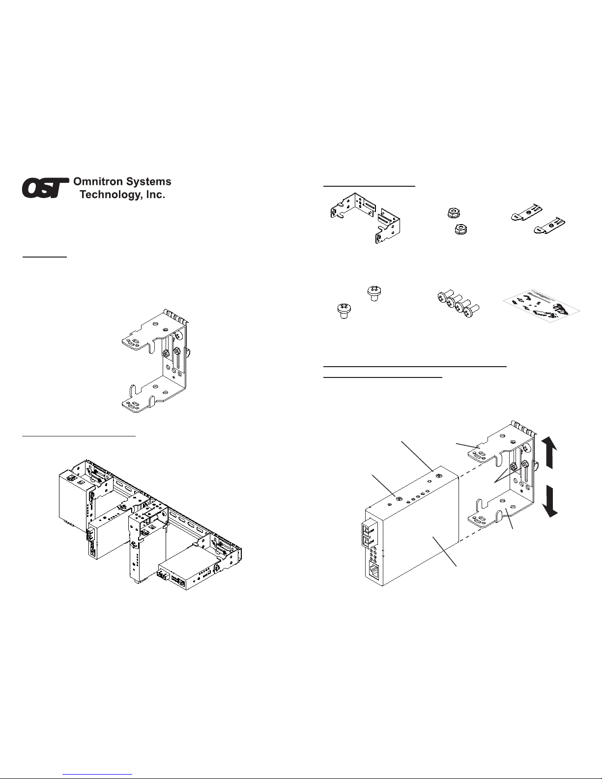
Figure 2. Mounting Orientations
UniDIN
™
DIN Rail Mounting Bracket Kit for
FlexPoint
™
and iConverter® User Manual
OVERVIEW
The Omnitron Universal DIN Rail Mounting Bracket model 8250-0 is designed
to provide DIN Rail mounting capabilities for the FlexPoint converter, FlexPoint
converter with DC Adapter , iConverter® Stand-Alone and iConverter 1-module
chassis. This kit contains all the necessary components to provide DIN Rail
mounting for several different mounting orientations.
[D]
[B]
[A]
[C]
Figure 1. Pre-assembled Configuration - Mounting Orientation [B]
MOUNTING ORIENTATIONS
This diagram illustrates a converter in four different DIN-Rail mounting orientations.
As shipped from the factory, the UniDIN is ready to be used in configuration [B].
Model: 8250-0
j
Rear Cover Screw
Converter
Front Cover
Screw
i
i
PACKAGE CONTENTS
(2) DIN Rail Bracket Hex
Nuts (Pre-assembled)
(2) DIN Rail Clips
(Pre-assembled)
(2) DIN Rail Clip Screws
(Pre-assembled)
(4) Bracket Mounting
Screws (In separate bag)
(2) DIN Rail Bracket
Halves (Pre-assembled)
User Manual
Item i
Item j
Item k
Item m Item n
ASSEMBLY AND MOUNTING INSTRUCTIONS
STEP 1. Adjusting Bracket Width
If bracket width adjustment is necessary, loosen the hex nut s ( j ) on the DIN
Rail bracket ( i ) and align the DIN Rail bracket width to match the width of the
media converter. After adjusting the DIN Rail bracket to the desired width,
tighten the hex nuts ( j ) to lock the DIN Rail bracket width.
Figure 3. Adjusting Bracket Width to Match Width of Media Converter
Page 2
k
m
m
m
i
[A] and [D]
[B]
[C]
n
n
Converter
Front Cover
Screw
i
[B], [C] and [D]
[A]
i
i
k
k
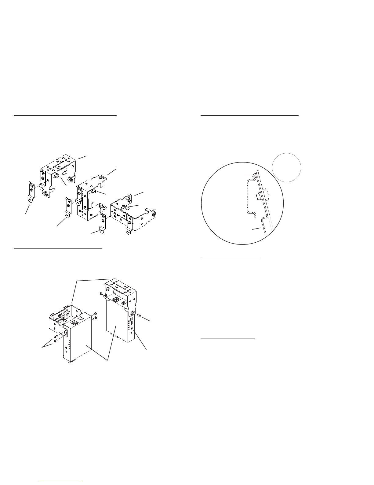
STEP 2. Optional Orientation Reconfiguration
If the desired mounting orientation is other than [B] as illustrated in Fig. 2,
remove the DIN Rail clips ( k ) from the bracket by removing the DIN Rail clip
screws ( m ). Determine the desired DIN Rail mounting orientation from the
Figure 2, and match the corresponding DIN Rail clip orientation in Figure 4.
Attach the DIN Rail clips ( k ) to the DIN Rail bracket holes in the DIN Rail
Bracket ( i ) and secure the DIN Rail clips ( k ) with DIN Rail clip screws ( m ).
Figure 4. Configuring Clip Mounting Orientation
STEP 3. Attaching Bracket to Converter
Remove the rear cover screws from the media converter casing. Align the
media converter to the bracket mounting holes that correspond with desired
orientation, then insert and fasten the supplied bracket mounting screws ( n )
to secure the media converter to the DIN Rail bracket ( i ).
Figure 5. Attaching Bracket to Converter
Form: 040-08250-001B 9/07
Patent Pending
DIN Rail
Cross Section
Close Up
Tab on the
DIN Rail Clip
Hooks on the
DIN Rail Clip
TECHNICAL SUPPORT:
For help with this product, contact our Technical Support:
Omnitron Systems Technology, Inc.
Phone: (949) 250-6510 Fax: (949) 250-6514
Address: 140 Technology Dr., #500 Irvine, CA 92618 USA
Email: support@omnitron-systems.com
URL: www.omnitron-systems.com
STEP 4. Mounting Converter to the DIN Rail
Attach the assembly to the DIN Rail, by aligning the hooks on the DIN Rail clip
( k ) to the upper edge of the DIN Rail. Rotate the assembly downward until the
DIN Rail clip tab engages and snaps to the bottom edge of the DIN Rail. Note
that the tab on the DIN Rail clip should always attach to the bottom of the DIN
Rail. Connect the external power supply to the rear of the installed media
converter.
Figure 6. Mounting/Dismounting Converter to/from DIN Rail
Dismounting from DIN Rail
To remove the converter assembly from the DIN Rail, hold the converter and
rotate upward to disengage the clip.
Mount
Dismount
 Loading...