

Page 1
TThheeSSAAMM33GGUUsseerrGGuuiidde
e
Document history
18th May 2007 : Start version 1.0
UK / Europe Office
Tel: +44 (0)8700 434040
Fax: +44 (0)8700 434045
info@omniinstruments.co.uk
www.omniinstruments.co.uk
Australia / Asia Pacific Office
Tel +61 (0)282 442 363
Fax +61 (0)294 751 278
info@omniinstruments.com.au
www.omniinstruments.com.au
USA / Canada Office
Tel +1-866-849-3441
Fax +1-866-628-8055
info@omniinstruments.net
www.omniinstruments.net
1
Page 2

UK / Europe Office
Tel: +44 (0)8700 434040
Fax: +44 (0)8700 434045
info@omniinstruments.co.uk
www.omniinstruments.co.uk
Australia / Asia Pacific Office
Tel +61 (0)282 442 363
Fax +61 (0)294 751 278
info@omniinstruments.com.au
www.omniinstruments.com.au
Contents
1. Introduction
2. Safety precautions
3. Radio frequency exposur
e - SAR
4. WEEE Directive 2002/96/EC - disposal of old electronic equipment
5. Packaging
6. Functionality
a. General
b. The RJ45 socket
c. The MiniB USB connector
d. The SMB-Jack 50Ω antenna connector
e. The USIM holder
f. The LED status
g. The Data cabl
e
USA / Canada Office
Tel +1-866-849-3441
Fax +1-866-628-8055
info@omniinstruments.net
www.omniinstruments.net
7. Electrical characteristics
a. Power consum
b. RF bands
c. Receive sensitivity
d. Conducted transmit power tolerances
e. Main antenna specifications
8. Operation
a. Using the USB port
b. Using the serial RS232 port
ption
2
Page 3
UK / Europe Office
Tel: +44 (0)8700 434040
Fax: +44 (0)8700 434045
info@omniinstruments.co.uk
www.omniinstruments.co.uk
Australia / Asia Pacific Office
Tel +61 (0)282 442 363
Fax +61 (0)294 751 278
info@omniinstruments.com.au
www.omniinstruments.com.au
USA / Canada Office
Tel +1-866-849-3441
Fax +1-866-628-8055
info@omniinstruments.net
www.omniinstruments.net
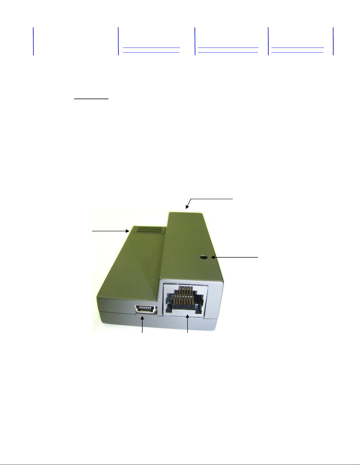
1. Introduction
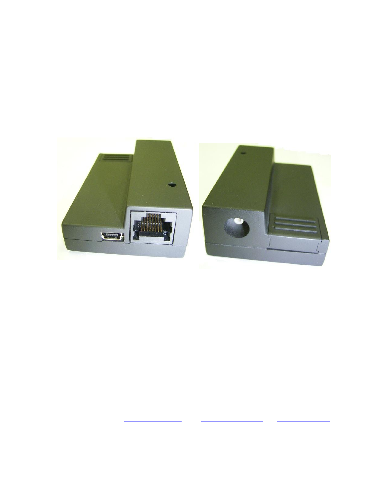
The SAM3G is a compact, light-weight, UMTS based modem. It provides GSM, GPRS, EDGE
and WCDMA connectivity.
- GSM, GPRS, EDGE : 850MHz, 900MHz, 1800MHz, 1900MHz
- UMTS, WCDMA/HSDPA : 850MHz, 1900MHz, 2100MHz
The SAM3G is designed for both mobile and fixed M2M applications. It has an RJ45 socket for
both input voltage and serial RS232 signals, a MiniB USB connector, a SMB-Jack for antenna
connection, a SIM holder and an LED indicator.
The SAM3G is capable of sending/receiving SMS, Circuit switched data and Packet-switched
data.
SIM holder
SMB-Jack antenna
connector
LED indicator
USB connector RJ45 for pow
er and serial
RS232
3
Page 4

UK / Europe Office
Tel: +44 (0)8700 434040
Fax: +44 (0)8700 434045
info@omniinstruments.co.uk
www.omniinstruments.co.uk
Australia / Asia Pacific Office
Tel +61 (0)282 442 363
Fax +61 (0)294 751 278
info@omniinstruments.com.au
www.omniinstruments.com.au
USA / Canada Office
Tel +1-866-849-3441
Fax +1-866-628-8055
info@omniinstruments.net
www.omniinstruments.net
2. Safety Precautions
The following safety precautions must be observed whenever the SAM3G modem is in operation
or in service. Failure to comply with these precautions violates the safety standards of the design,
manufacture and intended use of the product
- Switch off the SAM3G modem :
In hospitals or places where medical equipments may be in use.
In an aircraft
Refueling points
Explosive areas
- Restricted use of
the SAM3G
modem
Near any chemical plant
Near any Fuel depot
Areas with mobile phone warning signs
Respect national regulation
s on the use of cellular devices. Road safety always comes first
The SAM3G modem receives and transmit radio frequency energy while switched on,
therefore interference can occur if the SAM3G is near TVs, radios, PCs or any inadequately
shielded equipments.
3. Radio frequency exposure - SAR
The SAM3G modem is a low-power transceiver, similar to a typical handheld GSM/GPRS/UMTS
mobile phone. When it is turned on, it will emit low-level radio frequency energy.
There are different guidelines and standards around the world that govern the permitted levels of
radio frequency exposure for general population. The levels include a safety margin to a human
body.
The Specific Absorption rate (SAR) is a measure of the rate at which radio frequency energy is
absorbed by the body when exposed to radio frequency electromagnetic field. The SAR value is
determined at the highest certified power level in the laboratory conditions, but the actual SAR
level of the transceiver while operating can be well below this value. This is because the
transceiver is designed to use minimum power to connect to the network.
The SAM3G modem is approved to use in applications where the antenna is placed more than
20cm from th
For other applica
e body.
tions, the integrator is responsible for the local SAR requirements.
4
Page 5

UK / Europe Office
Tel: +44 (0)8700 434040
Fax: +44 (0)8700 434045
info@omniinstruments.co.uk
www.omniinstruments.co.uk
Australia / Asia Pacific Office
Tel +61 (0)282 442 363
Fax +61 (0)294 751 278
info@omniinstruments.com.au
www.omniinstruments.com.au
USA / Canada Office
Tel +1-866-849-3441
Fax +1-866-628-8055
info@omniinstruments.net
www.omniinstruments.net
4. WEEE directive 2002/96/EC, disposal of old electronic equipment
This symbol on the product indicates that this product shall not be treated as
household waste . It must be placed at an appropriate collection point for the recycling of
electrical and electronic equipments.
By ensuring the correct disposal of this equipment, it will help the environment and human’s
health. The recycling will help to conserve the natural resources.
The SAM3G product is RoHS compliant
5
Page 6

UK / Europe Office
Tel: +44 (0)8700 434040
Fax: +44 (0)8700 434045
info@omniinstruments.co.uk
www.omniinstruments.co.uk
5. Packaging
The SAM3G package consists of :
- A SAM3G modem
-
A data cable
- A one-page Specification of the SAM and its pinouts
- A SAM3G User Guide
The carton box diameter is 120mm x 95mm x 60mm
The Data cable is 2m long
The Label diameter is 50mm x 33mm
Australia / Asia Pacific Office
Tel +61 (0)282 442 363
Fax +61 (0)294 751 278
info@omniinstruments.com.au
www.omniinstruments.com.au
USA / Canada Office
Tel +1-866-849-3441
Fax +1-866-628-8055
info@omniinstruments.net
www.omniinstruments.net
The Power supply is available on request. It is recommended that the SAM3G is powered using a
12Vdc/1A power supply.
The Antenna is also availableon request. Make sure the correct antenna is used to get optimised
performance from the SAM3G.
6
Page 7

The SAM3G F
unctional Block Diagram
UK / Europe Office
Tel: +44 (0)8700 434040
Fax: +44 (0)8700 434045
info@omniinstruments.co.uk
www.omniinstruments.co.uk
Australia / Asia Pacific Office
Tel +61 (0)282 442 363
Fax +61 (0)294 751 278
info@omniinstruments.com.au
www.omniinstruments.com.au
USA / Canada Office
Tel +1-866-849-3441
Fax +1-866-628-8055
info@omniinstruments.net
www.omniinstruments.net
6. Functionality
a. General
The SAM3G modem consists of an RJ45 connector for serial port and input power, a miniB USB
connector, an SMB Jack
antenna connector and a SIM holder. The LED indicator, located on top,
indicates the SAM operating status.
SMB connector
LED Indicator
3G ENGINE
SIM Interface
Switching
Power
Supply
uController
RS232
Serial Data
Interface
MiniB
USB
Connector
RJ45
Socket
7
Page 8

UK / Europe Office
Tel: +44 (0)8700 434040
Fax: +44 (0)8700 434045
info@omniinstruments.co.uk
www.omniinstruments.co.uk
b. The RJ45 socket
Pin Signals Description
1 VIN Input voltage 5Vdc - 32Vdc
2
DCD Data Carrier Detect
3 N/U Not used
4 GND Common Ground
5 RXD Serial Data out of the SAM
6 TXD Serial Data into the SAM
7 RTS Ready to Send
8 CTS Clear to Send
c. The MiniB USB connector
Pin Signal
Australia / Asia Pacific Office
Tel +61 (0)282 442 363
Fax +61 (0)294 751 278
info@omniinstruments.com.au
www.omniinstruments.com.au
USA / Canada Office
Tel +1-866-849-3441
Fax +1-866-628-8055
info@omniinstruments.net
www.omniinstruments.net
1 VIN
2 D3 D+
4 N/C
5 GND
Important Note : RS232 and USB ports must not be connected/operated simultaneously
Pin5 Pin1 Pin8 Pin1
8
Page 9

UK / Europe Office
Tel: +44 (0)8700 434040
Fax: +44 (0)8700 434045
info@omniinstruments.co.uk
www.omniinstruments.co.uk
d. The SMB-Jack 50Ω antenna connector
e. The USIM holder
To insert the SIM card, remove the door by sliding it back toward the end. Make sure
the SIM card faces the right way as indicated on t
complies with 3GPP standards
Australia / Asia Pacific Office
Tel +61 (0)282 442 363
Fax +61 (0)294 751 278
info@omniinstruments.com.au
www.omniinstruments.com.au
USA / Canada Office
Tel +1-866-849-3441
Fax +1-866-628-8055
info@omniinstruments.net
www.omniinstruments.net
he box. Voltage levels over this USIM interface
f. The LED statu
The LED indication has the
- LED on steady : The SAM3G is on and connect
s
following status :
ed, but not transmitting/receiving data
- LED flashes slowly : The SAM3G is on and searching for network connection
- LED flashes intermittently : The SAM3G is in use (transmit/receive data)
- LED is off : No power
9
Page 10

UK / Europe Office
Tel: +44 (0)8700 434040
Fax: +44 (0)8700 434045
info@omniinstruments.co.uk
www.omniinstruments.co.uk
Australia / Asia Pacific Office
Tel +61 (0)282 442 363
Fax +61 (0)294 751 278
info@omniinstruments.com.au
www.omniinstruments.com.au
USA / Canada Office
Tel +1-866-849-3441
Fax +1-866-628-8055
info@omniinstruments.net
www.omniinstruments.net
g. The data cable
The data cable is 2m long. It consists of an RJ45 plug, a DB9-female connector and a 2-wire
input power.
5 4 3 2 1
9 8 7 6
DB9 Signals RJ45
1 DCD 2 Data Carrier D
2 RXD 5
Description
etect
Serial Data out of the SAM3G
3 TXD 6 Serial Data into the SAM3G
4 DTR 3 Not used
5 GND 4 Common Ground
6 DSR
7 RTS 7 Ready to Send
8 CTS 8 Clear to Send
9 RI
1 RED wire : Input voltage from 5Vdc to 32Vdc
4 BLACK wire : Power Ground
10
Page 11

UK / Europe Office
Tel: +44 (0)8700 434040
Fax: +44 (0)8700 434045
info@omniinstruments.co.uk
www.omniinstruments.co.uk
Australia / Asia Pacific Office
Tel +61 (0)282 442 363
Fax +61 (0)294 751 278
info@omniinstruments.com.au
www.omniinstruments.com.au
7. Electrical characteristics
a. Power consumption
Vin = 12Vdc HSDPA/WCDMA GSM/GPRS/EDGE
Low Power mode 4mA 4mA
Normal mode 90mA 80mA
USA / Canada Office
Tel +1-866-849-3441
Fax +1-866-628-8055
info@omniinstruments.net
www.omniinstruments.net
@ 0dBm
Tx power 151mA @ 15dBm Tx power 200mA @ 21dBm Tx power 250mA -
Maximum peak 500mA
@ 5dBm Tx power - 151mA
@ 13dBm Tx power - 130mA
@ 33dBm Tx power - 170mA
Maximum peak - 830mA
b. RF bands
GSM850 : Tx
= 824MHz - 849MHz, Rx = 869MH
z - 894MHz
EGSM900 : Tx = 880MHz - 915MHz, Rx = 925MHz - 960MHz
DCS1800 : Tx = 1710MHz - 1785MHz, Rx = 1805MHz - 1880MHz
PCS1900 : Tx = 1850MHz - 1910MHz, Rx = 1930MHz - 1990MHz
UMTS2100 : Tx = 1920MHz - 1980MHz, Rx = 2110MHz - 2170MHz
UMTS1900 : Tx = 1850MHz - 1910MHz, Rx = 1930MHz - 1990MHz
UMTS850 : Tx = 824MHz - 849MHz, Rx = 869MHz - 894MHz
c. Receive sensitivity
Band T
ypical Rx
Sensitivity Maximum Rx Sensitivity
(dBm) (dBm)
GSM850 (2% ber) CS -107.5 -106
EGSM900 (2% ber) CS -107.5 -106
DCS1800 (2% ber) CS -106.5 -105
PCS1900 (2% ber) CS -106.5 -105
UMTS2100(.1% ber) 12.2Kbps -110.5 -109
UMTS1900(.1% ber) 12.2Kbps -110.5 -109
UMTS850(.1% ber) 12.2Kbps -110.5 -110
11
Page 12

UK / Europe Office
Tel: +44 (0)8700 434040
Fax: +44 (0)8700 434045
info@omniinstruments.co.uk
www.omniinstruments.co.uk
Australia / Asia Pacific Office
Tel +61 (0)282 442 363
Fax +61 (0)294 751 278
info@omniinstruments.com.au
www.omniinstruments.com.au
d. Conducted Transmit Power tolerances
Parameter Conducted Tx Power Note
USA / Canada Office
Tel +1-866-849-3441
Fax +1-866-628-8055
info@omniinstruments.net
www.omniinstruments.net
GSM850 & GS
M900 CS +32dBm ±1dBm GMSK m
ode, connectorized (Cl.4)
+27dBm ±1dBm 8PSK mode, connectorized (Cl.E2)
DCS1800 & PCS1900 CS +29dBm ±1dBm GMSK mode, connectorized (Cl.1)
+626Bm ±1dBm 8PSK mode, connectorized (Cl.E2)
UMTS1900 & 850 12.2Kbps +23dBm ±1dBm connectorized (Cl.3)
UMTS2100 12.2Kbps +23dBm ±1dBm connectorized (Cl.3)
e. Main antenna specifications
Frequency band Netwo
rk type VSWR test frequen
cy
(MHz) (MHz)
824-894 GSM,GPRS,EDGE,UMTS Low : 824
CDMA Mid :
859
High : 894
880-960 GSM,GPRS,EDGE Low : 880
Mid : 920
High : 960
1710-1880 GSM,GPRS,EDGE Low : 1710
Mid : 1795
High : 1880
1850-1990 GSM,GPRS,EDGE,UMTS Low : 1850
CDMA Mid : 1920
High : 1990
1920-2170 UMTS (Tx : 1920-1980)
Low : 1920
Mid : 1950
High : 1980
(Rx : 2110-2170)
Mid : 2110
Mid : 2140
Mid : 2170
The maximum antenna gain recommended, for consideration against RF exposure and
ERP/EIRP limits, is :
- In Cellular band : 8dBi
- In PCS band : 4dBi
12
Page 13

UK / Europe Office
Tel: +44 (0)8700 434040
Fax: +44 (0)8700 434045
info@omniinstruments.co.uk
www.omniinstruments.co.uk
Australia / Asia Pacific Office
Tel +61 (0)282 442 363
Fax +61 (0)294 751 278
info@omniinstruments.com.au
www.omniinstruments.com.au
USA / Canada Office
Tel +1-866-849-3441
Fax +1-866-628-8055
info@omniinstruments.net
www.omniinstruments.net
8. Operation
The SAM3G can support either the USB port or the Serial RS232 port. The port
configuration is done at the point of sale. Do not operate these 2 ports at the same time !
8.1 Using the USB port
a. Installing the USB driver
Note : If the old driver version has been installed, it must be removed, before installing the latest
driver. To uninstall the old driver, follo
w these steps :
- Open the Control Panel
- Double click
System, Sy
stem Properties window appears
- Select the Hardware tab
- Select the Device Manager
- Expand the Universal Serial Bus controllers to show the installed devices.
- Right click
the Sierra Wireless
MC87xx device entry and choose Uninstall.
- Click OK to confirm.
Step1 : Locate and run the DriverInstaller.exe . Note that there is no feedback, just wait a few
oments for the program to run.
m
Step2 : Connec
t the SAM3G to the PC, using the supplied USB cable. Several Found New
Hardware balloons appear above the tool tray as the system detects the new devices. After the
devices are det
ected, the Device Manager
will show, in the following categories :
- Network Adapters : Sierra Wireless HSDPA Network adapter.
- Port (COM&LPT) :
Sierra Wireless AT Command port (UMTS)
Sierra Wireless CNS port (UMTS)
Sierra Wireless Data Port (UMTS)
Sierra Wireless DM Port (UMTS)
- Universal Ser
ial Bus Controllers : Sierra W
ireless MC87xx device
b. Installing the 3G_Watcher
Note : If the old Watcher has been installed, it must be removed before installing the latest
Watcher. To uninstall the old Watcher, follow these ste
ps :
- Open the Control Panel
- Double-click
-
Select Sierra Wireless 3G Watcher
Add or Remove programs
- Click Change/Remove
Step 1 : Run the 3G_Watcher.exe, the 3G_Watcher welcome-window, appears, click Next
Step 2 : Select Australia region, click Next
Step 3 : Select “ I accept the terms in the license agreement” , click Next
13
Page 14

UK / Europe Office
Tel: +44 (0)8700 434040
Fax: +44 (0)8700 434045
info@omniinstruments.co.uk
www.omniinstruments.co.uk
Australia / Asia Pacific Office
Tel +61 (0)282 442 363
Fax +61 (0)294 751 278
info@omniinstruments.com.au
www.omniinstruments.com.au
USA / Canada Office
Tel +1-866-849-3441
Fax +1-866-628-8055
info@omniinstruments.net
www.omniinstruments.net
Step 4 : Use the default folder, click Next
Step 5 : Click Install, then Finish
c. Connection
Connect the SAM3G to the PC using the supplied USB cable. After connection, the PC will
automatically detect the SAM3G and run the
3G_Watcher.
To set up the data profile, go to the “Tools” option, select “Connections” -> “Profile” then enter
Profile name, User name, Password, Access Point Name (APN) and Connection type. PDP type
default is IP.
8.2 Using the Serial RS232 port
The SAM3G has 2 different configurations for the serial port : General configuration and Meter
configuration.
a. General configuration :
In this configuration, the SAM3G’s default terminal speed is 115200bps, data format is 1+8+1.
There are only 4 serial data signals s
upported, namely RXD, TXD, RTS and CTS.
b. Meter configuration :
In this configuration, the SAM3G will be controlled by an internal micro-controller, its default
terminal speed is 9600bps, 1+8+1. Ther
e are 5 serial data signals supported, namely RXD,TXD,
RTS,CTS and DCD.
c. Connection :
To test the serial port configuration, follow these steps :
- Insert the USIM c
-
Connect the Antenna
ard into the SAM3G
- Connect the SAM3G to the PC’s COM port using the supplied serial cable (RJ45-DB9).
- On the PC, run a terminal program, ex. HyperTerminal, set the program speed at either
115200bps, or 9600bps.
- Connect the 12Vdc to the SAM3G Red+Black wires
14
Page 15

SAM3G typical connection to test the serial RS232 configuration
d. AT commands :
UK / Europe Office
Tel: +44 (0)8700 434040
Fax: +44 (0)8700 434045
info@omniinstruments.co.uk
www.omniinstruments.co.uk
Australia / Asia Pacific Office
Tel +61 (0)282 442 363
Fax +61 (0)294 751 278
info@omniinstruments.com.au
www.omniinstruments.com.au
USA / Canada Office
Tel +1-866-849-3441
Fax +1-866-628-8055
info@omniinstruments.net
www.omniinstruments.net
The SAM3G modem supports most of the AT commands specified in the following standards :
- 3GPP TS 27.005 : Control
SMS functions for devices on GSM/WCDMA networks
- 3GPP TS27.007 : Control devices operating on GSM/WCDMA networks
- ITU-T V.250 : Control serial communications over an asynchronous interface
For details of the AT commands, refer to the “Supported AT command reference” manual.
15
 Loading...