

Page 1
RuggedNet
™
GPoE+/Si
Unmanaged
4 and 8-Port PoE/PoE+ Switch
User Manual
38 Tesla, Irvine, CA 92618 USA
Phone: (949) 250-6510; Fax: (949) 250-6514
General and Copyright Notice
This publication is protected by U.S. and international copyright laws. All rights reserved. The whole
or any part of this publication may not be reproduced, stored in a retrieval system, translated,
transcribed, or transmitted, in any form, or by any means, manual, electric, electronic, electromagnetic,
mechanical, chemical, optical or otherwise, without prior explicit written permission of Omnitron
Systems Technology, Inc.
The following trademarks are owned by Omnitron Systems Technology, Inc.: FlexPointTM,
FlexSwitchTM, HybridNID®, iConverter®, miConverterTM, NetOutlook®, OmniLight®, OmniConverterTM,
RuggedNetTM, Omnitron Systems Technology, Inc.TM, OSTTM and the Omnitron logo.
All other company or product names may be trademarks of their respective owners.
The information contained in this publication is subject to change without notice. Omnitron Systems
Technology, Inc. is not responsible for any inadvertent errors.
Warranty
This product is warranted to the original purchaser (Buyer) against defects in material and
workmanship for a period of two (2) years from the date of shipment. A ve (5) warranty may be
obtained by the original purchaser by registering this product at www.omnitron-systems.com/support
within ninety (90) days from the date of shipment. During the warranty period, Omnitron will, at its
option, repair or replace a product which is proven to be defective with the same product or with a
product with at least the same functionality.
For warranty service, the product must be sent to an Omnitron designated facility, at Buyer’s expense.
Omnitron will pay the shipping charge to return the product to Buyer’s designated US address using
Omnitron’s standard shipping method.
Limitation of Warranty
The foregoing warranty shall not apply to defects resulting from improper or inadequate use and/
or maintenance of the equipment by Buyer, Buyer-supplied equipment, Buyer-supplied interfacing,
unauthorized modications or tampering with equipment (including removal of equipment cover by
personnel not specically authorized and certied by Omnitron), or misuse, or operating outside the
environmental specication of the product (including but not limited to voltage, ambient temperature,
radiation, unusual dust, etc.), or improper site preparation or maintenance.
No other warranty is expressed or implied. Omnitron specically disclaims the implied warranties of
merchantability and tness for any particular purpose.
The remedies provided herein are the Buyer’s sole and exclusive remedies. Omnitron shall not
be liable for any direct, indirect, special, incidental, or consequential damages, whether based on
contract, tort, or any legal theory.
Environmental Notices
The equipment covered by this manual must be disposed of or recycled in accordance with the
Waste Electrical and Electronic Equipment Directive (WEEE Directive) of the European Community
directive 2012/19/EU on waste electrical and electronic equipment (WEEE) which, together with
the RoHS Directive 2011/65/EU, for electrical and electronic equipment sold in the EU after July
1, 2006. Such disposal must follow national legislation for IT and Telecommunication equipment in
accordance with the WEEE directive: (a) Do not dispose waste equipment with unsorted municipal
and household waste. (b) Collect equipment waste separately. (c) Return equipment using collection
method agreed with Omnitron.
The equipment is marked with the WEEE symbol shown to indicate that it must be
collected separately from other types of waste. In case of small items the symbol
may be printed only on the packaging or in the user manual. If you have questions
regarding the correct disposal of equipment go to www.omniton-systems.com/support
or e-mail to Omnitron at intlinfo@omnitron-systems.com.
Page 2
Page 2
OmniConverter GPoE+/Si
User Manual
Product Overview
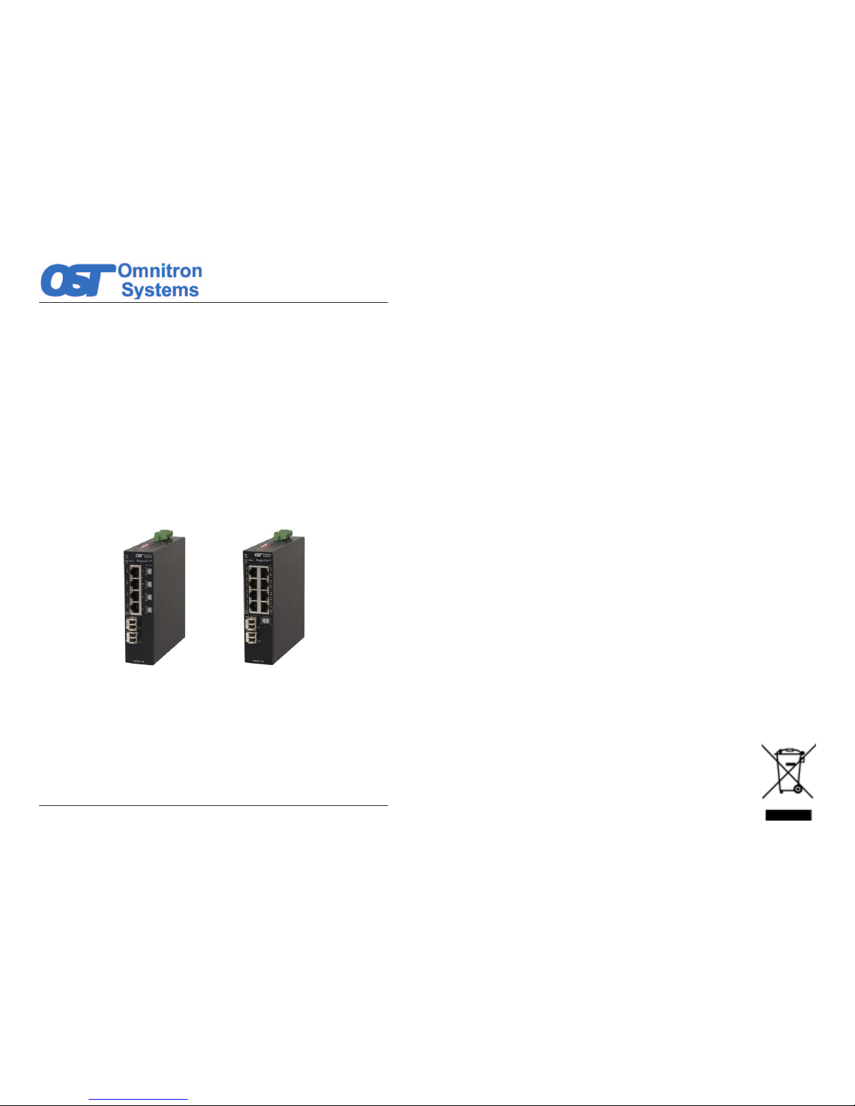
The
RuggedNet GPoE+/Si is a industrial ruggedized and temperature-hardened
unmanaged Ethernet switch
that features one or two 1000BASE-X Gigabit ber ports
and four or eight 10/100/1000BASE-T RJ-45 Power Sourcing Power-over-Ethernet
(PoE and PoE+) ports.
The GPoE+/Si functions can be congured using easily accessible DIP-switches.
RuggedNet GPoE+/Si 4 and 8-Port
The GPoE+/Si is a Power Sourcing Equipment (PSE) that provides up to 30W
PoE+ (IEEE 802.3at) per RJ-45 port and supports frame sizes up to 10,240 bytes.
The GPoE+/Si automatically negotiates and delivers the power level required by its
Powered Device (PD) partner. When negotiating to PoE (IEEE 802.3af) it delivers
up to 15.4 Watts per RJ-45 port. When negotiating to PoE+ (IEEE 802.3at) it delivers
up to 30 Watts per RJ-45 port.
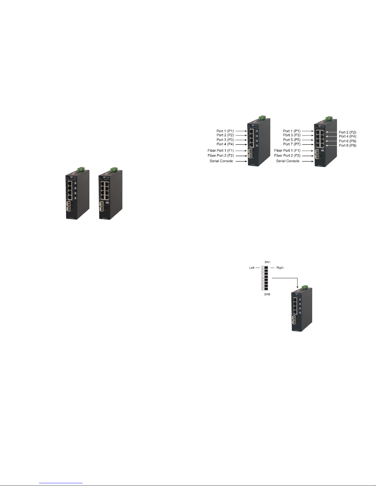
Front Panel
The front of the GPoE+/Si provides access to the RJ-45 PoE, SFP and Fixed-Fiber
ports. The SFP ports support 1000BASE-X SFP ber and 10/100/1000BASE-T
copper transceivers.
RJ-45 PoE, SFP and Fixed-Fiber Ports
The RJ-45 PoE Ethernet port supports 10BASE-T, 100BASE-TX and 1000BASE-T
protocols, auto-negotiation, auto MDI/MDI-X crossover and can be manually forced
to a specic speed and duplex mode.
The SFP interfaces support SERDES 1000BASE-X ber transceivers and SGMII
10/100/1000BASE-T copper transceivers. The SFP interfaces operate in autonegotiation and support full duplex operation.
Fixed-ber 1000BASE-X connectors are available with multimode (MM) dual ber,
single-mode (SM) dual ber and single-mode single-ber (SF) options. They support
ST, SC and LC connectors.
Page 3
Front Panel Layout
Reset Button
A Rest Button is available on the front of the switch to restore the switch to factory
default values. Press and hold the reset button for more than 5 seconds to restore
the switch to factory default values.
Installation Procedure
1) Congure DIP-switches
2) Apply AC Power
3) Connect Cables
4) Verify Operation
1) Congure DIP-switches
DIP-switches are located on the side of the RuggedNet GPoE+/Si. The DIP-switches
are used to congure modes of operation, networking features and PoE reset.
DIP-switch Bank Locations
Page 4
Page 3
The table below provides a description of each DIP-switch position and function.
Switch 1 Fiber Port 2 Fiber Ports
1
Mode Of Operation
2
3 Reserved
Fiber Redundancy
4 Reserved
5 MAC Learning
6 Pause
7 L2CP
8 PoE Reset
DIP-switch Denitions
SW1 and SW2: Mode of Operation
The GPoE+/Si supports Switch, Directed Switch and Dual Device mode.
The modes are described with MAC learning enabled. When MAC learning is
disabled, unicast packets are forwarded to all ports.
SW1 SW2 Function
DOWN DOWN Switch Mode (factory default)
DOWN UP Directed Switch Mode
UP DOWN Dual Device Mode - Switch Mode
UP UP Dual Device Mode - Directed Switch Mode
Modes of Operation
Switch Mode
When congured for Switch Mode (factory default), the module operates as a
standard layer 2 switch. Data ow will follow MAC address mapping.
Page 5
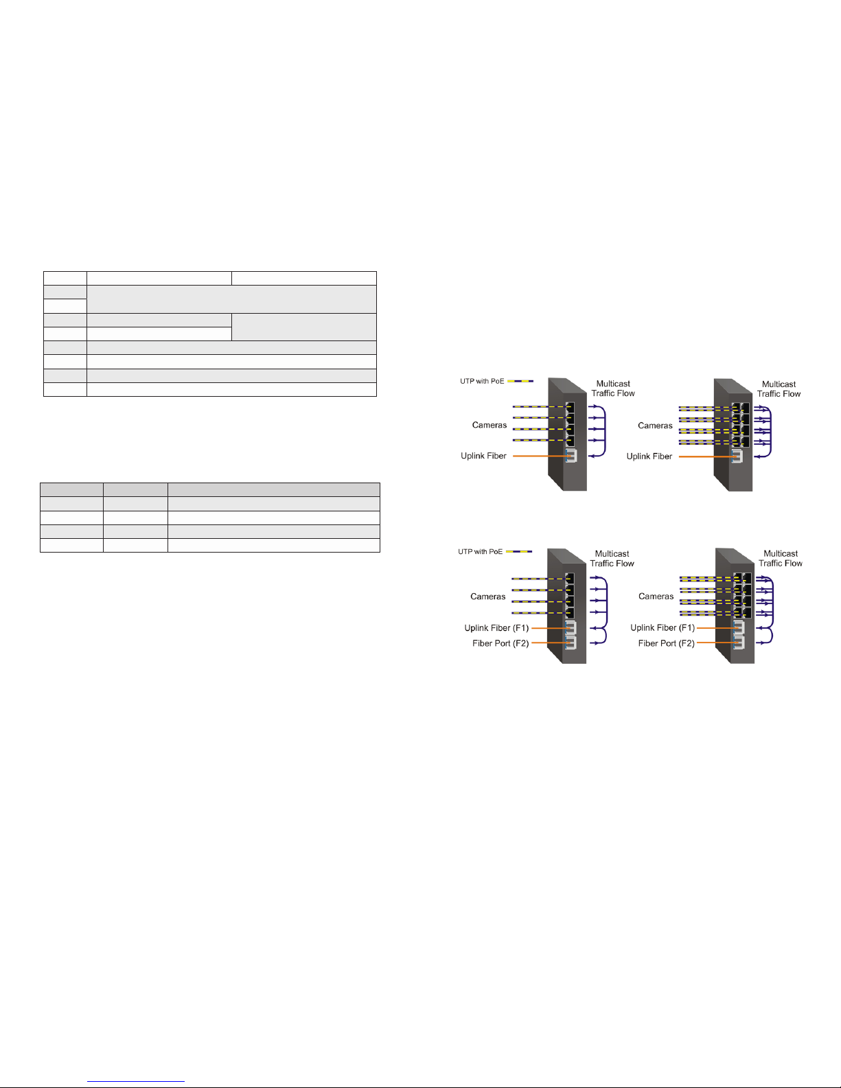
Directed Switch Mode
When an 4-Port model is congured for Directed Switch Mode, trafc from Ports
P1 - P4 is only forwarded to the ber uplink port F1, preventing the broadcast trafc
from ooding other network ports. Incoming trafc from F1 follows MAC address
mapping.
When an 8-Port model is congured for Directed Switch Mode, trafc from Ports
P1 - P8 is only forwarded to the ber uplink port F1, preventing the broadcast trafc
from ooding other network ports. Incoming trafc from F1 follows MAC address
mapping.
Directed Switch Mode Single Fiber Port
Models with two ber ports follow the same RJ-45 data ow as above, with the
addition of ber port F2 also being forwarded to the ber uplink port F1.
Directed Switch Mode Dual Fiber Port
Page 6
Page 4

Two ber ports models can be congured for Directed Switch Mode and Fiber
Redundancy (per DIP-switches 3 and 4), trafc is forwarded to both the primary
and secondary ber ports. The secondary port will block all trafc while the primary
port is active. When the primary port goes down, the secondary port will be active
and all trafc will be forwarded out the secondary port (F2).
Directed Switch Mode with Fiber Redundancy
Dual Device Mode
Dual Device Mode is only supported on GPoE+/Si with two ber ports.
When congured for Dual Device Mode, the GPoE+/Si is congured as two logically
independent Layer 2 switches. On the 4-Port models, ber port F1 is associated
with RJ-45 Ports P1 - P2 and ber port F2 is associated with RJ-45 Ports P3 - P4.
On the 8-Port models, ber port F1 is associated with RJ-45 Ports P1 - P4 and ber
port F2 is associated with RJ-45 Ports P5 - P8. Data ow will follow MAC address
mapping.
Dual Device Mode
Page 7
On the 4-Port models congured for Dual Device Mode and Directed Switch Mode,
the trafc from Ports 1 - 2 is only forwarded to ber port F1 and Ports 3 - 4 are only
forwarded to ber port F2. On the 8-Port models congured for Dual Device Mode
and Directed Switch Mode, the trafc from Ports 1 - 4 is only forwarded to ber port
F1 and Ports 5 - 8 are only forwarded to ber port F2. This prevents broadcast
trafc from ooding other network ports. Incoming trafc from F1 and F2 follows
MAC address mapping.
Dual Device with Directed Switch Mode
SW3 and SW4: Fiber Redundancy
SW3 and SW4 are valid on models with two ber ports.
The modes are described with MAC learning enabled. When MAC learning is
disabled, the GPoE+/Si will send data to all ports.
SW3 SW4 Function
DOWN DOWN Switch Mode (factory default)
DOWN UP Switch Mode (factory default)
UP DOWN Redundant Mode - no return to primary (F1)
UP UP Redundant Mode - return to primary (F1)
Fiber Redundancy
Fiber redundancy is only supported on GPoE+/Si models with two ber ports.
When congured for Redundant Mode “no return to primary”, the ber ports operate
as redundant links. A fault on the primary ber port F1, will cause a fail over to the
secondary ber port F2 within 50msec. F1 will become the secondary port once the
port has been restored because “no return to primary” has been selected.
Page 8
Page 5

Page 10
drop PoE power when a loss of receive link on F1 is detected and RJ-45 ports 3 - 4
will drop PoE power when a loss of receive link on F2 is detected. On the 8-Port
models, RJ-45 ports 1 - 4 will drop PoE power when a loss of receive link on F1
is detected and RJ-45 ports 5 - 8 will drop PoE power when a loss of receive link
on F2 is detected.
2) Apply DC Power
Power source should be available within 5 ft. of the chassis. The over current
protection for connection with centralized DC shall be provided in the building
installation, and shall be a UL listed circuit breaker rated 20 Amps, and installed
per the National Electrical Code, ANSI/NFPA-70.
This equipment requires 46 to 57VDC @ 2.72 Amp max rated power. For PoE+, this
equipment requires 52 to 57VDC (see Specication table). Appropriate overloading
protection should be provided on the DC power source outlets utilized.
WARNING: OnlyaDC power source that complies with
safety extra low voltage (SELV) requirements can be
connected to the DC-input power supply.
WARNING REGARDING EARTHING GROUND:
o
o
o
o
This equipment shall be connected to the DC supply
system earthing electrode conductor or to a bonding
jumper from an earthing terminal bar or bus to which the
DC supply system earthing electrode is connected.
This equipment shall be located in the same immediate
area (such as adjacent cabinets) as any other equipment
that has a connection between the earthed conductor of
the same DC supply circuit and the earthing conductor,
and also the point of earthing of the DC system. The DC
system shall not be earthed elsewhere.
The DC supply source is to be located within the same
premises as this equipment.
There shall be no switching or disconnecting devices in
the earthed circuit conductor between the DC source and
the earthing electrode conductor.
Locate the DC circuit breaker of the external power source, and switch the circuit
breaker to the OFF position.
Prepare a power cable using a three conductor insulated wire (not supplied) with a
14 AWG gauge minimum. Cut the power cable to the length required.
Strip approximately 3/8 of an inch of insulation from the power cable wires.
Connect the power cables to the GPoE+/Si by fastening the stripped ends to the
DC power connector.
WARNING: Note the wire colors used in making the positive, negative and ground
connections. Use the same color assignment for the connection at the circuit breaker.
Connect the power wires to the circuit breaker and switch the circuit breaker ON.
If any units are installed, their Power LED should indicate the presence of power.
Installation of the equipment should be such that the air ow in the front, back, side
and top vents of the chassis are not compromised or restricted.
Redundant Fiber
When congured for Redundant Mode “return to primary’, a fault on the primary ber
port F1, will cause a fail over to the secondary ber port F2 within 50msec. The
module will return to the primary ber port F1 after the ber link has been restored
for 6 seconds.
SW5: MAC Learning - “MAC Learning/Off”
When this DIP-switch is in the “MAC Learning” position (factory default), all ports
on the module will learn the source MAC address of each received packet and
store the address so packets destined for the stored addresses can be forwarded
to the appropriate port on the module. When the DIP-switch is in the “Off” position,
learning is turned off and all received unicast packets are forwarded to all ports.
SW6: Pause - “Pause Off/On”
Setting the DIP-switch to the Down “Pause Off” position (factory default) congures
the module to advertise no Pause capability on all ports. Setting this DIP-switch to the
Up “On” position congures the module to advertise Symmetrical and Asymmetrical
Pause capability to all ports.
SW7: L2CP - “L2CP Tunnel/Discard”
When this DIP-switch is in the Down “L2CP Tunnel” position (factory default), all
L2CP frames will be tunneled through the module. When this DIP-switch is in the
Up “Discard” position, all L2CP frames will be discarded.
SW8: PSE Reset - “Off/PoE Reset”
The GPoE+/Si can be congured to disable (reset) the PoE output power for 2
seconds after a loss of receive link on any ber port. This feature is typically used
to allow a PD to re-initialize after a failure on the incoming ber.
When this DIP-switch is in the Down “Off” position (factory default), PoE output
power does not reset on ber link loss. When this DIP-switch is in the Up “PoE
Reset” position, the module will disable PoE output power for 2 seconds following
a loss of receive link on any ber port.
When ber redundancy is enabled, the loss of ber link on either F1 or F2 will not
cause the PD to be re-initialized even though the PSE Reset is enabled. The PD
will be re-initialized on a loss of receive link on both ber ports.
When Dual Device Mode is enabled, the loss of ber link will re-initialize the PDs
associated with the that ber port. On the 4-Port models, RJ-45 ports 1 - 2 will
Page 9
Page 6

Page 11
Top View with DC Power Connector
NEVER ATTEMPT TO OPEN THE CHASSIS OR
SERVICE THE POWER SUPPLY. OPENING THE
CHASSIS MAY CAUSE SERIOUS INJURYOR DEATH.
THERE ARE NO USER REPLACEABLE OR
SERVICEABLE PARTS IN THIS UNIT.
WARNING!!!
3) Connect Cables
a. When using SFP models, insert the SFP ber transceiver into the SFP
receptacle on the front of the module (see the SFP Data Sheet 091-17000-001
for supported Gigabit transceivers).
NOTE: The release latch of the SFP ber transceiver must be in the closed
(up) position before insertion.
b. Connect an appropriate multimode or single-mode ber cable to the ber port
on the front of the module. It is important to ensure that the transmit (TX) is
attached to the receive side of the transceiver at the other end and the receive
(RX) is attached to the transmit side. When using single-ber (SF) models, the
TX wavelength must match the RX wavelength at the other end and the RX
wavelength must match the TX wavelength at the other end.
c. Connect the Ethernet 10/100/1000 RJ-45 port using a Category 5 or better
cable to an external 10BASE-T, 100BASE-TX or 1000BASE-T Ethernet device.
RJ-45 Pinout Alternative B
1 Vport Positive
2 Vport Positive
3 Vport Negative
6 Vport Negative
Voltage Polarity of Alternative A PoE Power
Page 12
4) Verify Operation
Verify the GPoE+/Si is operational by viewing the LED indicators.
Power
LED Indicators
Legend Indicator Description
Pwr
OFF Unit not powered
Green - ON Unit powered
Amber - ON Over temperature condition
Power LED Indicators
Fiber Ports
LED Indicators - SFP Models
Legend Indicator Description
100
OFF No link
Green - ON Port linked at 100Mbps
Green - Blinking at 10Hz Port data activity at 100Mbps
Green - Blinking at 1Hz Port linked at 100Mbps and in redundant standby mode
Amber - Blinking at 1Hz
Port linked at 100Mbps and receiving Far End Fault Indicator
(FEFI)
1000
OFF No link
Green - ON Port linked at 1000Mbps
Green - Blinking at 10Hz Port data activity at 1000Mbps
Green - Blinking at 1Hz Port linked at 1000Mbps and in redundant standby mode
Amber - Blinking at 1Hz Port linked at 1000Mbps and receiving AN Remote Fault
NOTE: 100M operation is only supported using copper SFP transceivers.
Fiber LED Indicator - SFP Models
Fiber Ports
LED Indicators - Fixed Fiber Models
Legend Indicator Description
1000
OFF No link
Green - ON Port linked at 1000Mbps
Green - Blinking at 10Hz Port data activity at 1000Mbps
Green - Blinking at 1Hz Port linked at 1000Mbps and in redundant standby mode
Amber - Blinking at 1Hz Port linked at 1000Mbps and receiving AN Remote Fault
Fiber LED Indicators - Fixed Fiber Models
Page 7

Page 13
RJ-45 Ports
LED Indicators
Legend Indicator Description
100
OFF No link
Green - ON Port linked at 100Mbps
Green - Blinking at 10Hz Port data activity at 100Mbps
Amber -ON Port linked at 100Mbps Half-duplex
Amber - Blinking at 10Hz Port data activity at 100Mbps Half-duplex
1000
OFF No link
Green - ON Port linked at 1000Mbps
Green - Blinking at 10Hz Port data activity at 1000Mbps
Amber -ON Port linked at 1000Mbps Half-duplex
Amber - Blinking at 10Hz Port data activity at 1000Mbps Half-duplex
10
(100+1000)
OFF No link
Green - ON Port linked at 10Mbps
Green - Blinking at 10Hz Port data activity at 10Mbps
Amber -ON Port linked at 10Mbps Half-duplex
Amber - Blinking at 10Hz Port data activity at 10Mbps Half-duplex
PoE/PSE
Green - Blinking at 1Hz Port PSE is active and supplying 15.4W
Green - Blinking at 10Hz Port PSE is active and supplying 30W
Amber - ON Port PSE error/inactive
Amber - Blinking at 1Hz
Port PSE inactive due to resistance too low (< 15k ohms) or
short circuit detected
Amber - Blinking at 10Hz
Port PSE inactive due to resistance to high (33k to 500k
ohms)
OFF Port PSE inactive
RJ-45 LED Indicators
Page 14
Specications
Description
RuggedNet GPoE+/Si
10/100/1000BASE-T to 1000BASE-X
Ruggedized Unmanaged PoE+ Ethernet Switch
Standard
Compliances
IEEE 802.3, IEEE 802.3af (15.40 watts max),
IEEE 802.3at (30 watts max)
Environmental
REACH, RoHS2 and WEEE
PoE Modes
IEEE Alternate A (Alt A)
Frame Size Up to 10,240 bytes
Port Types
Copper:
Fiber:
Serial:
10/100/1000BASE-T (RJ-45)
1000BASE-X (ST, SC, LC, SFP)
RJ-45
Cable Types
Copper:
Fiber:
Serial:
EIA/TIA 568A/B, Cat 5 UTP and higher
Multimode: 50/125, 62.5/125µm
Single-mode: 9/125µm
Category 3 and higher
DC Power
Requirements
DC Input:
(4 RJ-45 Ports)
(8 RJ-45 Ports)
+/-46 to +/-57VDC
1
;
2.7A @ 48VDC
2 Pin Terminal (isolated)
5.2A @ 48VDC
2 Pin Terminal (isolated)
Dimensions
W: 1.5” x D: 5.5” x H: 5.14”
L: 38.1 mm x B: 139.7 mm x H: 130.5 mm
Weight
4 RJ-45 Ports:
8 RJ-45 Ports:
TBD lb.; TBD grams
TBD lb.; TBD grams
Operating
Temperature
-40 to 75°C (-20°C cold start)
Humidity 5 to 95% (non-condensing)
Altitude -100m to 4,000m (operational)
MTBF (hours)
4 RJ-45 Ports:
8 RJ-45 Ports:
DC Power: TBD
DC Power: TBD
Warranty 5 year warranty with 24/7/365 free Technical Support
1
A minimum of 52VDC is required to guarantee 25.5 watts at 100 meters on Cat 5 or better cable.
Page 8

Page 15
Customer Support Information
If you encounter problems while installing this product, contact Omnitron Technical
Support:
Phone: (949) 250-6510
Fax: (949) 250-6514
Address: Omnitron Systems Technology, Inc.
38 Tesla
Irvine, CA 92618, USA
Email: support@omnitron-systems.com
URL: www.omnitron-systems.com
040-09560-001A 10/17
 Loading...