

Page 1
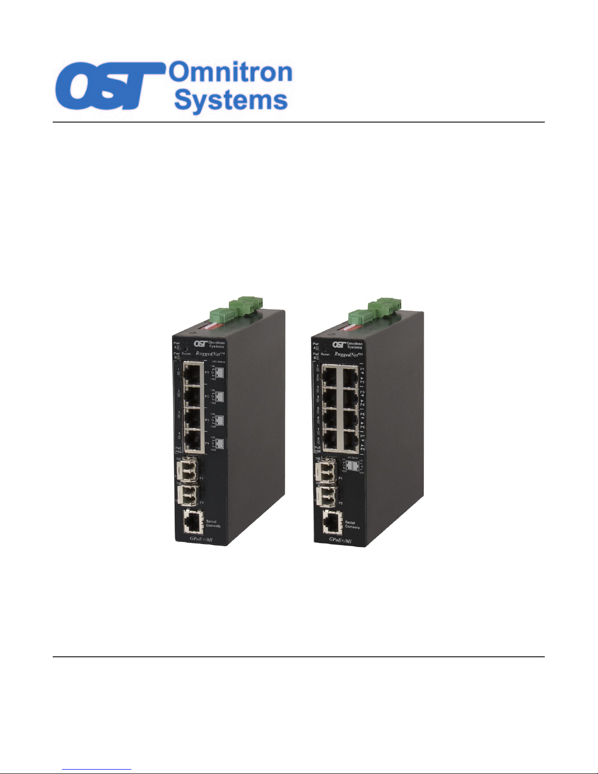
RuggedNet® GPoE+/Mi
4 and 8-Port PoE/PoE+ Fiber Switches
USER MANUAL
Firmware Release 2.1
Page 2

Table of Contents
1.0 Overview ..........................................................................................................................5
1.1 New Features...................................................................................................................... 5
2.0 Port Structure ..................................................................................................................5
2.1 Overview ............................................................................................................................. 5
2.1.1 Serial Console Port ............................................................................................................................... 5
2.1.2 RJ-45 PoE, SFP and Fixed-Fiber Ports ................................................................................................ 6
2.1.3 Reset Button ............................................................................................................................................ 6
2.2 ConguringDIP-switches .............................................................................................. 6
2.2.1 SW1 and SW2: Mode of Operation ........................................................................................................ 7
2.2.2 SW3 and SW4: Fiber Redundancy ......................................................................................................... 9
2.2.3 SW5: MAC Learning - “MAC Learning/Off” ...........................................................................................10
2.2.4 SW6: Pause - “Pause Off/On” ...............................................................................................................10
2.2.5 SW7: L2CP - “L2CP Tunnel/Discard” .................................................................................................... 10
2.2.6 SW8: PSE Reset - “Off/PoE Reset” ...................................................................................................... 11
3.0 ApplyDCPower ............................................................................................................ 11
4.0 Connect Cables .............................................................................................................12
5.0 Verify Operation ............................................................................................................13
6.0 CommandLineInterface(CLI) .....................................................................................15
6.1 CLICommands................................................................................................................. 17
6.1.1 Authentication, Authorization and Accounting (AAA) ............................................................................. 18
6.1.2 Access Control List (ACL) ......................................................................................................................23
6.1.3 BandwidthProle(BWP) .......................................................................................................................25
6.1.4 Cable Test (CABLETEST) ..................................................................................................................... 29
6.1.5 Contact (CONTACT) .............................................................................................................................. 30
6.1.6 Class of Service (COS) ..........................................................................................................................32
6.1.7 File Directory (DIR) ................................................................................................................................ 35
6.1.8 Ethertype (ETHERTYPE) ......................................................................................................................36
6.1.9 Load Firmware (FWLOAD) .................................................................................................................... 37
6.1.10 IP (IP) .....................................................................................................................................................38
6.1.11 Link Layer Discovery Protocol (LLDP) ................................................................................................... 40
6.1.12 Physical Location (LOCATION) .............................................................................................................44
6.1.13 Link Redundancy (LR) ........................................................................................................................... 46
6.1.14 MAC Table (MACTABLE) ....................................................................................................................... 47
6.1.15 Module Settings (MODULE) .................................................................................................................. 49
6.1.16 Ping (PING) ........................................................................................................................................... 52
6.1.17 Port Attribute (PORT) ............................................................................................................................. 53
6.1.18 Port Access (PORTACCESS) ................................................................................................................ 56
6.1.19 Port Statistics (PORTSTAT) ................................................................................................................... 57
6.1.20 Protocol (PROTOCOL) .......................................................................................................................... 58
6.1.21 Power Sourcing Equipment (PSE)......................................................................................................... 59
6.1.22 Restart (RESTART) ............................................................................................................................... 62
6.1.23 Restore to Factory Defaults (RESTORE) .............................................................................................. 63
6.1.24 IEEE 802.1w Rapid Spanning Tree Protocol (RSTP) ............................................................................ 64
6.1.25 Save (SAVE) ..........................................................................................................................................67
6.1.26 Create and Run a Script File (SCRIPT) ................................................................................................. 68
6.1.27 Firmware Update using Serial Console (SERUPDATE) ........................................................................69
Page 2
Page 3

6.1.28 SFP (SFP) .............................................................................................................................................71
6.1.29 DisplaytheCommonCongurationParameters(SHOWCONFIG) ....................................................... 73
6.1.30 Simple Network Management Protocol (SNMP).................................................................................... 74
6.1.31 Simple Network Time Protocol (SNTP) ..................................................................................................75
6.1.32 Entry Screen Message Display (SPLASH) ............................................................................................ 76
6.1.33 Secure Shell (SSH) ................................................................................................................................ 77
6.1.34 DIP-SwitchConguration(SWITCH) ..................................................................................................... 79
6.1.35 VLANInterfaceConguration(SWITCHPORT) .................................................................................... 80
6.1.36 SyslogServerConguration(SYSLOG) ................................................................................................ 82
6.1.37 Time (TIME) ........................................................................................................................................... 84
6.1.38 SNMP Trap Host (TRAPHOST) .............................................................................................................85
6.1.39 SNMP Traps (TRAPS) ........................................................................................................................... 86
6.1.40 UserConguration(USER) ................................................................................................................... 88
6.1.41 Firmware Version (VER) ........................................................................................................................ 90
6.1.42 VLAN Table (VLAN) ............................................................................................................................... 91
6.1.43 Zone (ZONE) ......................................................................................................................................... 92
7.0 WebInterface ................................................................................................................93
7.1 Overview ........................................................................................................................... 93
7.1.1 Login ...................................................................................................................................................... 93
7.1.2 Status Screens ......................................................................................................................................94
7.1.2.1 Module Overview ................................................................................................................... 94
7.1.2.2 Module Information ................................................................................................................ 96
7.1.2.3 Port Statistic Overview ........................................................................................................... 97
7.1.2.4 Port Statistics Detailed ........................................................................................................... 98
7.1.2.5 SFP Port Info ....................................................................................................................... 100
7.1.3 HardwareCongurationScreens.........................................................................................................103
7.1.3.1 DIP Switch ........................................................................................................................... 103
7.1.3.2 Port / Interface Overview ..................................................................................................... 105
7.1.3.3 Port / Interface Detailed ....................................................................................................... 107
7.1.3.4 I/O Pins ................................................................................................................................ 110
7.1.4 Service Management ........................................................................................................................... 11 2
7.1.4.1 Module ................................................................................................................................. 112
7.1.4.2 IPConguration ................................................................................................................... 114
7.1.4.3 SNMP ................................................................................................................................... 11 6
7.1.4.4 Time and Date...................................................................................................................... 119
7.1.4.5 NTP / SNTP ......................................................................................................................... 120
7.1.4.6 LLDP .................................................................................................................................... 121
7.1.5 Service Activation ................................................................................................................................ 125
7.1.5.1 VLANConguration ............................................................................................................. 125
7.1.5.2 VLAN Interface ..................................................................................................................... 127
7.1.5.3 Rate Limiting & Shaping ...................................................................................................... 129
7.1.5.4 CoS / QoS ............................................................................................................................ 135
7.1.5.5 Protection ............................................................................................................................. 137
7.1.6 Security ................................................................................................................................................ 141
7.1.6.1 Authenticate, Authorize, Account (AAA) ............................................................................... 141
7.1.6.2 Access Control List (ACL) .................................................................................................... 146
7.1.6.3 Secure Shell (SSH) .............................................................................................................. 147
7.1.6.4 User ..................................................................................................................................... 149
7.1.7 Maintenance ........................................................................................................................................ 153
7.1.7.1 Firmware Upgrade ............................................................................................................... 153
7.1.7.2 Module Maintenance ............................................................................................................ 155
7.1.7.3 Browser Settings .................................................................................................................. 156
7.1.7.4 Syslog .................................................................................................................................. 158
7.1.7.5 SNMP Traps Screen ............................................................................................................ 160
7.1.7.6 Splash Screen ...................................................................................................................... 162
Page 3
Page 4

8.0 Specications .............................................................................................................164
9.0 Appendix A: Firmware Update ..................................................................................165
9.1 Overview ......................................................................................................................... 165
9.2 SaveCurrentSettings ................................................................................................... 165
9.3 CopytheFilestoYourHardDrive ................................................................................ 165
9.5 UpdatetheGPoE+/Mi .................................................................................................... 165
9.5.1 Updating the Firmware Using FTP ......................................................................................................165
9.5.2 Updating the Firmware Using the Web Interface ................................................................................. 167
10.0 WarrantyandCopyright .............................................................................................170
11.0 CustomerSupportInformation .................................................................................171
Page 4
Page 5
1.0 OVERVIEW
The
RuggedNet GPoE+/Mi is a industrial ruggedized and temperature-hardened
managed Ethernet switch
that features one or two 1000BASE-X Gigabit ber ports and four or eight 10/100/1000BASE-T RJ-45
Power Sourcing Power-over-Ethernet (PoE and PoE+) ports.
The GPoE+/Mi functions can be congured using easily accessible DIP-switches or using Web, Telnet,
SSH or Serial Console management interfaces.
Web, Telnet and SSH management access is available through any Ethernet port on the GPoE+/Mi.
The GPoE+/Mi is Power Sourcing Equipment (PSE) that provides up to 30W PoE+ (IEEE 802.3at) per
RJ-45 port and supports frame sizes up to 10,240 bytes.
The GPoE+/Mi automatically negotiates and delivers the power level required by its Powered Device
(PD) partner. When negotiating to PoE (IEEE 802.3af) it delivers up to 15.4 Watts per RJ-45 port. When
negotiating to PoE+ (IEEE 802.3at) it delivers up to 30 Watts per RJ-45 port.
1.1 NEWFEATURES
Firmware release 2.1 adds SNMP v1/v2c support as well as SNMP alarm notication. New CLI commands
include snmp, traps and traphosts. New web screens were added for the conguration of SNMP parameters.
NetOutlook® supports 2.1 features with IP discovery and alarm reporting.
2.0 PORTSTRUCTURE
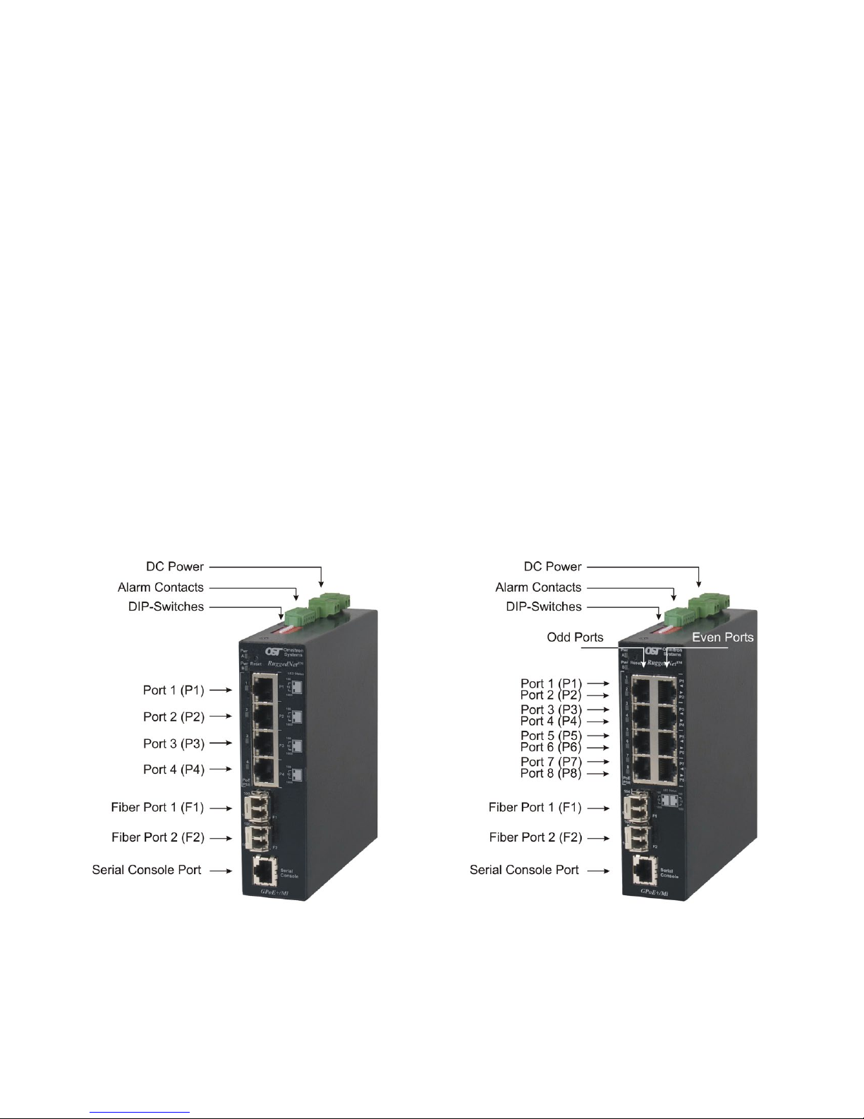
2.1 OVERVIEW
The front of the GPoE+/Mi provides access to the management (serial console), RJ-45 PoE, SFP or FixedFiber ports. The SFP ports support 1000BASE-X SFP ber and 10/100/1000BASE-T copper transceivers.
2.1.1 Serial Console Port
To congure the GPoE+/Mi using the serial port, attach a DB-9 serial (RS-232) equipped computer with
terminal emulation software such as Procomm or Putty to the serial port on the GPoE+/Mi using a RJ-45
to DB-9 serial cable (not included).
Front Panel Layout
Page 5
Page 6
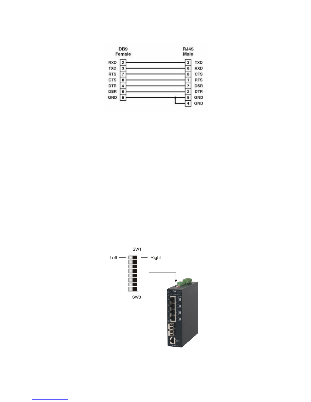
The port is a standard RS-232 asynchronous serial interface. The serial ports is congured for 57,600bps,
1 stop, 8 data, parity none. The serial adapter cable pin-outs are illustrated below.
Standard RJ-45 to DB-9 serial cable pin-out
2.1.2 RJ-45PoE,SFPandFixed-FiberPorts
The RJ-45 PoE Ethernet port supports 10BASE-T, 100BASE-TX and 1000BASE-T protocols, autonegotiation, auto MDI/MDI-X crossover and can be manually forced to a specic speed and duplex mode.
The SFP interfaces support SERDES 1000BASE-X ber transceivers and SGMII 10/100/1000BASE-T
copper transceivers. The SFP interfaces operate in auto-negotiation and support full duplex operation.
Fixed-ber 1000BASE-X connectors are available with multimode (MM) dual ber, single-mode (SM)
dual ber and single-mode single-ber (SF) options. They support ST, SC and LC connectors.
2.1.3 ResetButton
A reset button is available on the front of the switch to restore the switch to factory default values. Press
and hold the reset button for more than 5 seconds to restore the switch to factory default values.
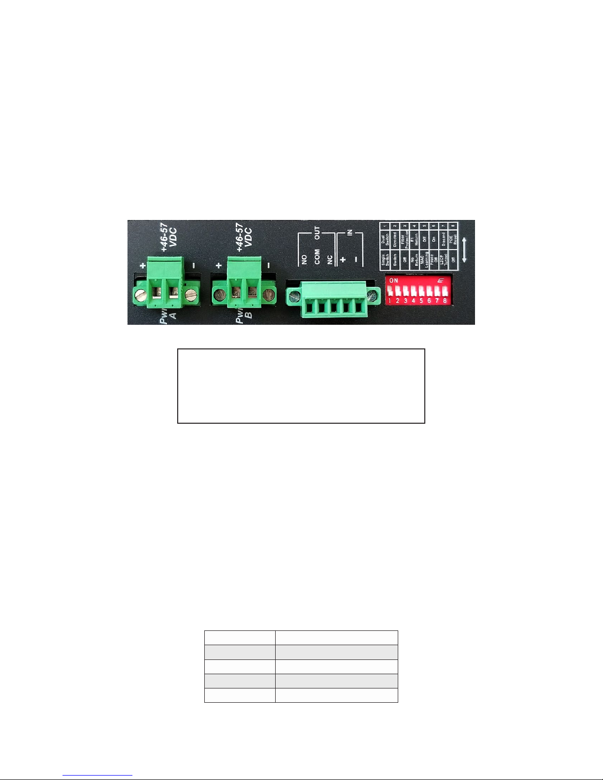
2.2 CONFIGURINGDIP-SWITCHES
DIP-switches are located on the top of the RuggedNet GPoE+/Mi. The DIP-switches are used to congure
modes of operation, networking features and PoE reset. Any change in the DIP-switches will immediately
take effect.
DIP-switch Bank Locations
Page 6
Page 7

The table below provides a description of each DIP-switch position and function.
Switch Position Function
SW1 & SW2
SW3 & SW4
SW5
SW6
SW7
SW8
LEFT
RIGHT
LEFT
RIGHT
LEFT MAC Learning (factory default)
RIGHT OFF - MAC Learning Disabled
LEFT Pause OFF - Pause Disabled (factory default)
RIGHT ON - Pause Enabled
LEFT L2CP Tunnel (factory default)
RIGHT L2CP Tunnel Discard
LEFT OFF - PoE Reset Disabled (factory default)
RIGHT PoE Reset
Mode of Operation (See Section 2.2.1)
Fiber Redundancy (See Section 2.2.2)
DIP-switch Denitions
2.2.1 SW1andSW2:ModeofOperation
The GPoE+/Mi supports Switch, Directed Switch and Dual Device modes.
The modes are described with MAC learning enabled. When MAC learning is disabled, unicast packets
are forwarded to all ports.
SW1 SW2
LEFT LEFT Switch Mode (factory default) Switch Mode (factory default)
LEFT RIGHT Directed Switch Mode Directed Switch Mode
RIGHT LEFT Reserved Dual Device Mode - Switch Mode
RIGHT RIGHT Reserved Dual Device Mode - Directed Switch Mode
1 Fiber Port 2 Fiber Ports
Function
Modes of Operation
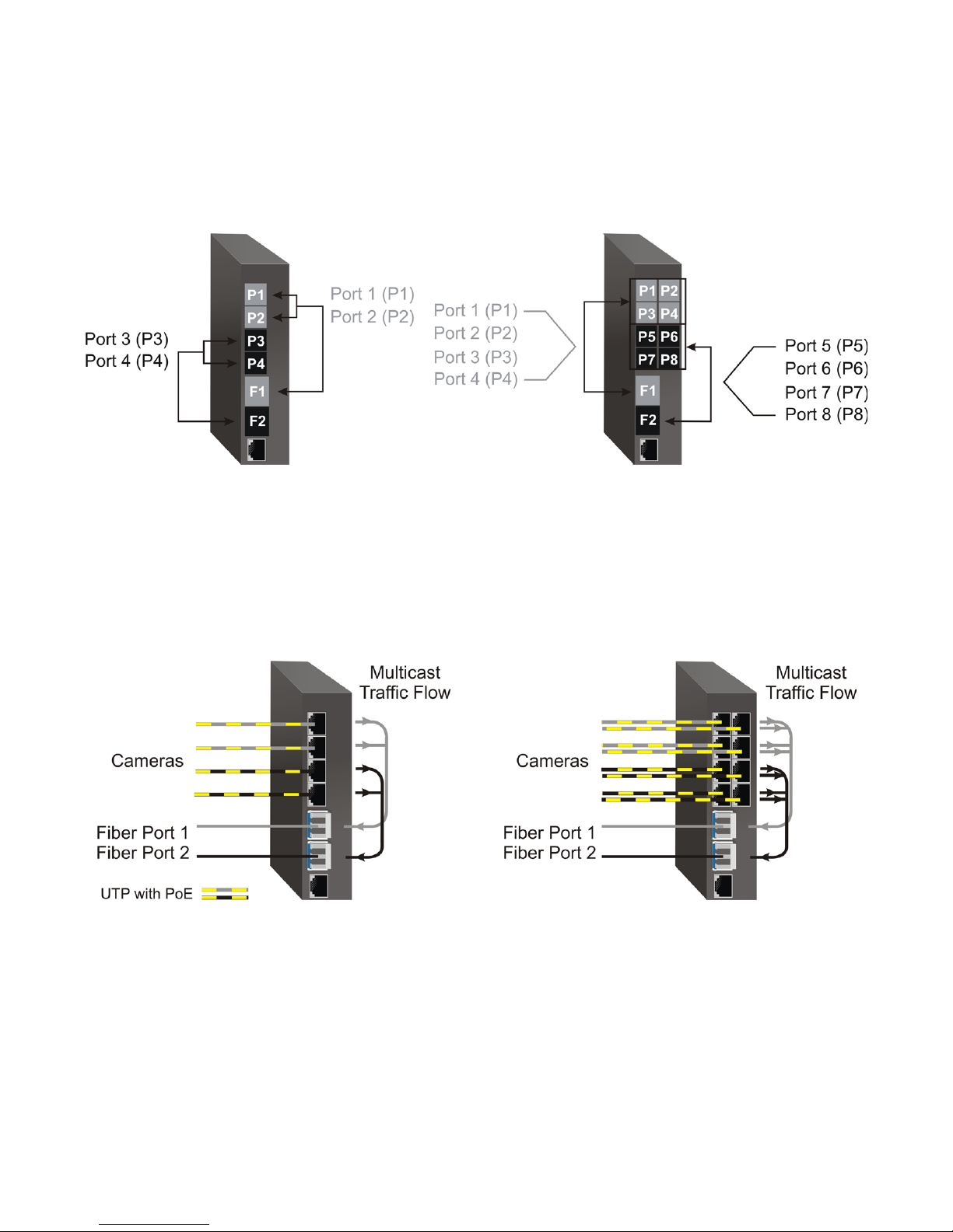
Switch Mode
When congured for Switch Mode (factory default), the module operates as a standard layer 2 switch. Data
ow will follow MAC address mapping.
Directed Switch Mode
When an 4-Port model is congured for Directed Switch Mode, trafc from Ports P1 - P4 is only forwarded
to the ber uplink port F1, preventing the broadcast trafc from ooding other network ports. Incoming
trafc from F1 follows MAC address mapping.
When an 8-Port model is congured for Directed Switch Mode, trafc from Ports P1 - P8 is only forwarded
to the ber uplink port F1, preventing the broadcast trafc from ooding other network ports. Incoming
trafc from F1 follows MAC address mapping.
Page 7
Page 8
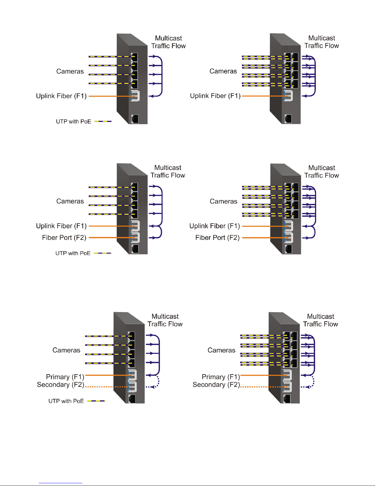
Directed Switch Mode Single Fiber Port
Models with two ber ports follow the same RJ-45 data ow as above, with the addition of ber port F2
also being forwarded to the ber uplink port F1.
Directed Switch Mode Dual Fiber Port
Two ber ports models can be congured for Directed Switch Mode and Fiber Redundancy (per DIP-switches
3 and 4). Trafc is forwarded to both the primary (F1) and secondary (F2) ber ports. The secondary port
will block all trafc while the primary port is active. When the primary port goes down, the secondary
port will be active and all trafc will be forwarded out the secondary port (F2).
Directed Switch Mode with Fiber Redundancy
Page 8
Page 9
Dual Device Mode
Dual Device Mode is only supported on GPoE+/Mi with two ber ports.
When congured for Dual Device Mode, the GPoE+/Mi is congured as two logically independent Layer
2 switches. On the 4-Port models, ber port F1 is associated with RJ-45 Ports P1 - P2 and ber port F2 is
associated with RJ-45 Ports P3 - P4. On the 8-Port models, ber port F1 is associated with RJ-45 Ports P1
- P4 and ber port F2 is associated with RJ-45 Ports P5 - P8. Data ow will follow MAC address mapping.
Dual Device Mode
On the 4-Port models congured for Dual Device Mode and Directed Switch Mode, the trafc from Ports
1 - 2 is only forwarded to ber port F1 and Ports 3 - 4 are only forwarded to ber port F2. On the 8-Port
models congured for Dual Device Mode and Directed Switch Mode, the trafc from Ports 1 - 4 is only
forwarded to ber port F1 and Ports 5 - 8 are only forwarded to ber port F2. This prevents broadcast
trafc from ooding other network ports. Incoming trafc from F1 and F2 follows MAC address mapping.
2.2.2 SW3andSW4:FiberRedundancy
SW3 and SW4 are valid on models with two ber ports.
The modes are described with MAC learning enabled. When MAC learning is disabled, the GPoE+/Mi
will send data to all ports.
Dual Device with Directed Switch Mode
Page 9
Page 10
SW3 SW4
LEFT LEFT Reserved Switch Mode (factory default)
LEFT RIGHT Reserved Switch Mode (factory default)
RIGHT LEFT Reserved Fiber Redundancy Mode - no return to primary (F1)
RIGHT RIGHT Reserved Fiber Redundancy Mode - return to primary (F1)
1 Fiber Port 2 Fiber Ports
Function
Fiber Redundancy
Fiber redundancy is only supported on GPoE+/Mi models with two ber ports.
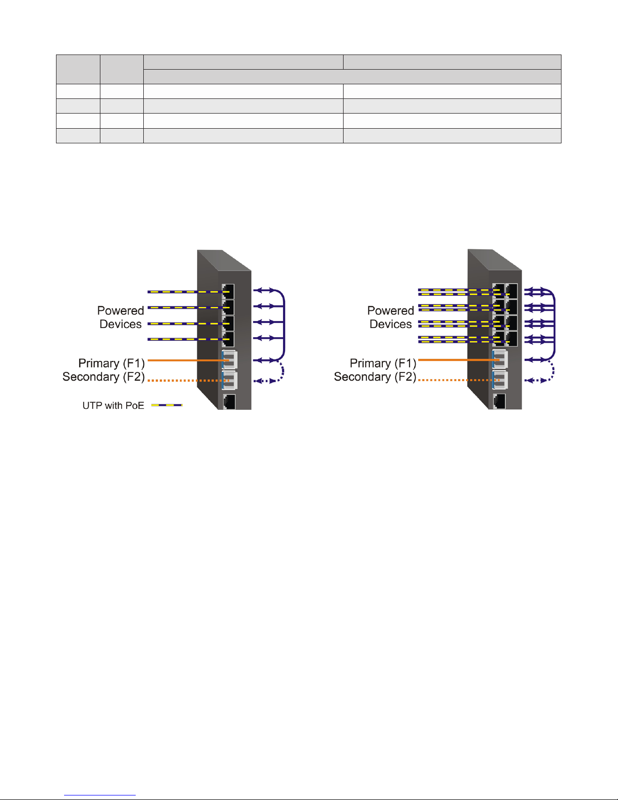
When congured for Fiber Redundancy Mode no return to primary, the ber ports operate as redundant
links. A fault on the primary ber port F1, will cause a fail over to the secondary ber port F2 within
50msec. F1 will become the secondary port once the port has been restored because “no return to primary”
has been selected.
Redundant Fiber with Switch Mode
When congured for Fiber Redundancy Mode return to primary, a fault on the primary ber port F1, will
cause a fail over to the secondary ber port F2 within 50msec. The module will return to the primary ber
port F1 after the ber link has been restored for 6 seconds.
2.2.3 SW5:MACLearning-“MACLearning/Off”
When this DIP-switch is in the MAC Learning position (factory default), all ports on the module will learn
the source MAC address of each received packet and store the address so packets destined for the stored
addresses can be forwarded to the appropriate port on the module. When the DIP-switch is in the OFF
position, learning is turned off and all received unicast packets are forwarded to all ports.
2.2.4 SW6:Pause-“PauseOff/On”
Setting the DIP-switch to the Pause Off position (factory default) congures the module to advertise no
Pause capability on all ports. Pause congures the ow control functionality for the module, including
pause mode advertisement and pause functionality.
Setting this DIP-switch to the ON position congures the module to advertise Symmetrical and Asymmetrical
Pause capability to all ports.
2.2.5 SW7:L2CP-“L2CPTunnel/Discard”
When this DIP-switch is in the L2CP Tunnel position (factory default), all L2CP frames are tunneled through
the module. When this DIP-switch is in the Discard position, all L2CP frames are discarded.
Page 10
Page 11

2.2.6 SW8:PSEReset-“Off/PoEReset”
The GPoE+/Mi can be congured to disable (reset) the PoE output power for 5 seconds after a loss of
receive link on any ber port. This feature is typically used to allow a PD to re-initialize after a failure on
the incoming ber.
When this DIP-switch is in the OFF position (factory default), PoE output power does not reset on ber
link loss. When this DIP-switch is in the PoE Reset position, the module will disable PoE output power
for 5 seconds following a loss of receive link on any ber port.
When ber redundancy is enabled, the loss of ber link on either F1 or F2 will not cause the PD to be reinitialized even though the PSE Reset is enabled. The PD will be re-initialized on a loss of receive link
on both ber ports.
When Dual Device Mode is enabled, the loss of ber link will re-initialize the PDs associated with the that
ber port. On the 4-Port models, RJ-45 ports 1 - 2 will drop PoE power when a loss of receive link on F1
is detected and RJ-45 ports 3 - 4 will drop PoE power when a loss of receive link on F2 is detected. On
the 8-Port models, RJ-45 ports 1 - 4 will drop PoE power when a loss of receive link on F1 is detected and
RJ-45 ports 5 - 8 will drop PoE power when a loss of receive link on F2 is detected.
The PoE Reset function is also available through the web management. See Section 7.1.3.2 Port / Interface
Overview.
3.0 APPLYDCPOWER
Power source should be available within 5 ft. of the chassis. The over current protection for connection
with centralized DC shall be provided in the building installation, and shall be a UL listed circuit breaker
rated 20 Amps, and installed per the National Electrical Code, ANSI/NFPA-70.
For PoE, the 4-Port model requires 46 to 57VDC @ 2.72 Amp max rated power and the 8-Port model
requires 46 to 57VDC @ 5.2 Amp max rated power. For PoE+, this equipment requires 52 to 57VDC.
Appropriate overloading protection should be provided on the DC power source outlets utilized.
WARNING: OnlyaDC power source that complies with
safety extra low voltage (SELV) requirements can be
connected to the DC-inputpower supply.
WARNING REGARDING EARTHING GROUND:
o
This equipment shall be connected to the DC supply
system earthing electrode conductor or to a bonding
jumper from an earthing terminal bar or bus to which the
DC supply system earthing electrode isconnected.
This equipment shall be located in the same immediate
o
area (such as adjacent cabinets) as any other equipment
that has a connection between the earthed conductor of
the same DC supply circuit and the earthing conductor,
and also the point of earthing of the DC system. The DC
system shall not be earthed elsewhere.
The DC supply source is to be located within the same
o
premises as this equipment.
There shall be no switching or disconnecting devices in
o
the earthed circuit conductor between the DC source and
the earthing electrode conductor.
Locate the DC circuit breaker of the external power source, and switch the circuit breaker to the OFF position.
Prepare a power cable using a three conductor insulated wire (not supplied) with a 14 AWG gauge minimum.
Cut the power cable to the length required.
Page 11
Page 12
Strip approximately 3/8 of an inch of insulation from the power cable wires.
Connect the power cables to the GPoE+/Mi by fastening the stripped ends to the DC power connector.
WARNING: Note the wire colors used in making the positive, negative and ground connections. Use the
same color assignment for the connection at the circuit breaker.
Connect the power wires to the circuit breaker and switch the circuit breaker ON. If any units are installed,
their Power LED should indicate the presence of power.
Installation of the equipment should be such that the air ow in the front, back, side and top vents of the
chassis are not compromised or restricted.
Depending on the model number of the module, a second power source is available (as shown). Use the
same power supply installation procedure for the second power supply.
Rear View with DC Power Connector
WARNING!!!
NEVER ATTEMPT TO OPEN THE CHASSIS OR
SERVICE THE POWER SUPPLY. OPENING THE
CHASSIS MAY CAUSE SERIOUS INJURYOR DEATH.
THERE ARE NO USER REPLACEABLE OR
SERVICEABLE PARTS IN THIS UNIT.
4.0 CONNECTCABLES
a. When using SFP models, insert the SFP ber transceiver into the SFP receptacle on the front of the
module (see the SFP Data Sheet 091-17000-001 for supported Gigabit transceivers).
NOTE: The release latch of the SFP ber transceiver must be in the closed (up) position before
insertion.
b. Connect an appropriate multimode or single-mode ber cable to the ber port on the front of the module.
It is important to ensure that the transmit (TX) is attached to the receive side of the transceiver at the
other end and the receive (RX) is attached to the transmit side. When using single-ber (SF) models,
the TX wavelength must match the RX wavelength at the other end and the RX wavelength must match
the TX wavelength at the other end.
c. Connect the Ethernet 10/100/1000 RJ-45 port using a Category 5 or better cable to an external 10BASE-T,
100BASE-TX or 1000BASE-T Ethernet device.
RJ-45 Pinout Alternative A
1 Vport Positive
2 Vport Positive
3 Vport Negative
6 Vport Negative
Voltage Polarity of Alternative A PoE Power
Page 12
Page 13

d. An alarm relay is available to detect a user congured event. The three contacts closure pins can be
congured for normally open (pin 1 and 2) or normally closed (pin 3 and 2) operation. The relay
contacts support 110VDC/125VAC Maximum Voltage at a maximum current of up to 2 amps. Use the
supplied connector to attach the wire to the external alarm. Use 16 - 24 AWG wire.
e. An alarm input is available for detecting external events such as door open or closed (pin 4 and 5).
The alarm input provides 3.3VDC to detect an external open or shorted condition. Use the supplied
connector to attach the wire to the external alarm. Use 16 - 24 AWG wire.
5.0 VERIFYOPERATION
Verify the GPoE+/Mi is operational by viewing the LED indicators.
Power
LEDIndicators
Legend Indicator Description
OFF Unit not powered
Pwr
Legend Indicator Description
1000
Green - ON Unit powered
Green - Blinking at 1Hz
Indicates reset button has been pressed for more than 5 seconds and the
module is being restored to factory default values
Power LED Indicators
Fiber Ports
LEDIndicators-FixedFiberModels
OFF No link
Green - ON Port linked at 1000Mbps
Green - Blinking at 10Hz Port data activity at 1000Mbps
Green - Blinking at 1Hz Port linked at 1000Mbps and in redundant standby mode
Amber - Blinking at 1Hz Port linked at 1000Mbps and receiving Auto Negotiation Remote Fault
Fiber LED Indicators - Fixed Fiber Models
Fiber Ports
LEDIndicators-SFPModels
Legend Indicator Description
OFF No link
Green - ON Port linked at 100Mbps
100
1000
Green - Blinking at 10Hz Port data activity at 100Mbps
Green - Blinking at 1Hz Port linked at 100Mbps and in redundant standby mode
Amber - Blinking at 1Hz Port linked at 100Mbps and receiving Far End Fault Indicator
OFF No link
Green - ON Port linked at 1000Mbps
Green - Blinking at 10Hz Port data activity at 1000Mbps
Green - Blinking at 1Hz Port linked at 1000Mbps and in redundant standby mode
Amber - Blinking at 1Hz Port linked at 1000Mbps and receiving Auto Negotiation Remote Fault
Fiber LED Indicator
NOTE: 10M and 100M operation is only supported using copper SFP transceivers. When negotiated to 10M, both the
100 and 1000 LEDs will be ON (blinking).
Page 13
Page 14

RJ-45Ports
LEDIndicators
Legend Indicator Description
OFF No link
Green - ON Port linked at 100Mbps
100
1000
10
(100+1000)
PoE/PSE
Green - Blinking at 10Hz Port data activity at 100Mbps
Amber -ON Port linked at 100Mbps Half-duplex
Amber - Blinking at 10Hz Port data activity at 100Mbps Half-duplex
OFF No link
Green - ON Port linked at 1000Mbps
Green - Blinking at 10Hz Port data activity at 1000Mbps
Amber -ON Port linked at 1000Mbps Half-duplex
Amber - Blinking at 10Hz Port data activity at 1000Mbps Half-duplex
OFF No link
Green - ON Port linked at 10Mbps
Green - Blinking at 10Hz Port data activity at 10Mbps
Amber -ON Port linked at 10Mbps Half-duplex
Amber - Blinking at 10Hz Port data activity at 10Mbps Half-duplex
Green - ON Port PSE is active
Amber - ON Port PSE error/inactive
Amber - Blinking at 1Hz
Amber - Blinking at 10Hz Port PSE inactive due to resistance too high (33k to 500k W)
OFF Port PSE inactive
Port PSE inactive due to resistance too low (< 15k W) or short circuit
detected
RJ-45 LED Indicators
NOTE: The PSE LED may turn Amber (ON) when a non-PD device is connected to the port.
Page 14
Page 15

6.0 COMMANDLINEINTERFACE(CLI)
To access the Command Line Interface, connect to the serial console port on the front of the module per
Section 2.2.
Each module is congured with the following defaults:
IP
IP 1 Address 192.168.1.220
IP 1 Subnet Mask 255.255.255.0
IP 1 Gateway 192.168.1.1
Protocols
IP enabled
TELNET enabled
FTP disabled
DHCP Client disabled
Flow Control disabled
Passwords
Serial public (username: admin)
FTP public (username: admin)
Telnet public (username: admin)
SNMPv1/v2c
Read public
Write private
SNMPv1/v2c agent enabled
User 1 type admin
User 1 name admin
User 1 password public
General SNMP Parameters
SNMP trap type SNMPv2c
SNMP UDP Trap Port Number 162
The GPoE+/Mi supports a common password per user account for the Serial port, Telnet, FTP and SSH.
The password is congured using the user command. Passwords for SNMPv1 are congured using the
snmp command.
It is highly recommended that the passwords be changed in order to prevent unauthorized access to the
module.
Page 15
Page 16

Once accessed, the Password Entry screen will be displayed. Type the username and password. Press
<ENTER>.
Omnitron Systems Technology, Inc. GPoE+/Mi
Copyright 2017-2018 OST, Inc.
-----------------------------------------------------------------------------
Omnitron Systems Technology Technical Support: (949) 250-6510
38 Tesla Sales/Products: (800) 675-8410
Irvine, CA 92618 On the web at: www.omnitron-systems.com
-----------------------------------------------------------------------------
IP address 192.168.1.220
MAC 00-06-87-02-87-50
Serial number 00720087
GPoE+/Mi login:
The 4-Port GPoE+/Mi is used to show all menu examples in the following sections.
Page 16
Page 17

6.1 CLICOMMANDS
The commands are presented in alphabetical order and are not meant as a conguration guide. Each
command has an explanation and conguration example.
Enter ? or help to view the options.
>
CLI Command summary
For more help on a specic command, type the <command> -h
Command Description
? command summary (same as help command)
aaa authentication, authorization, accounting conguration
acl access control list conguration for management access
bwp bandwidth prole conguration
cabletest cable test for a copper port
contact contact closure status
cos class of service conguration
dir directory of the existing les
ethertype ethertype tag identication conguration
exit exit the CLI session
fwload rmware load conguration
h command summary (same as help command)
help command summary
ip internet protocol conguration
lldp link layer discovery protocol (LLDP) conguration
location location conguration
lr link redundancy conguration
mactable mac table status
module module global conguration
ping ping conguration
port port attribute conguration
portaccess port access conguration
portstat port statistic conguration
protocol protocol conguration
pse power source equipment (PSE) conguration
restart restart module
restore restore module defaults
rstp rapid spanning tree conguration
save save conguration changes into permanent memory
script create and execute script les
serupdate upload rmware update via the serial port
sfp small form pluggable port information
showcong show basic conguration information status
snmp simple network management protocol user conguration
sntp simple network time protocol conguration
splash splash screen warning message conguration
ssh secure shell conguration
switch physical switch conguration
switchport vlan interface conguration
syslog system log message conguration
traphost snmp trap host conguration
traps snmp trap conguration
time time of day conguration
user user conguration
ver version status
vlan vlan conguration
x exit the CLI session
zone time zone list
>
Page 17
Page 18

Keyboard shortcuts are displayed with the menu of module commands.
CLI keyboard shortcuts:
Ctrl+A move the cursor to the beginning of the line
Ctrl+B move the cursor backward one character
Ctrl+D delete the character at the cursor
Ctrl+E move the cursor to the end of the line
Ctrl+F move the cursor forward one character
Ctrl+K erase characters from the cursor to the end of the line
Ctrl+L redisplay the current line on the console
Ctrl+N or down arrow, display the next command in the commands history buffer
Ctrl+P or up arrow, display the previous command in the commands history buffer
Ctrl+R starts a new line with the same command previously shown
Ctrl+U delete the whole line
Ctrl+W delete the word to the left of the cursor
Ctrl+X erase character from the cursor to the beginning of the line
Esc+F move the cursor forward one word, skipping white space
Esc+B move the cursor backward one word, skipping white space
Backspace remove the character to the left of the cursor
Delete remove the character to the right of the cursor
>
6.1.1 Authentication,AuthorizationandAccounting(AAA)
The module supports Authentication, Authorization and Accounting (AAA), Remote Authentication Dial-In
User Service (RADIUS), Terminal Access Controller Access-Control System Plus (TACACS+) and Port
Based Network Access Control (802.1X).
AAA is a framework for controlling access to computer resources, enforcing policies, auditing usage and
providing the information necessary to bill for services. AAA congures the client type method for console,
FTP, SSH, Telnet interfaces and the authentication method TACACS+, RADIUS, local, or none.
Remote Authentication Dial-In User Service (RADIUS) is a client/server system that secures networks
against unauthorized access. When a user tries to access a specic module, the RADIUS server is contacted
for validation of a correct user name and password.
The user receives one of the following responses from the RADIUS server:
ACCEPT - The user is authenticated.
REJECT - The user is not authenticated and is prompted to reenter the username and password, or
access is denied.
CHALLENGE - A challenge is issued by the RADIUS server and is attempting to collect additional
information from the user including username and password.
CHANGE PASSWORD - A request is issued by the RADIUS server asking the user to select a new
password.
RADIUS is a stateless protocol using UDP, running on Port 1812 between the Client and the Server. A
shared secret key is used to encrypt passwords and exchange responses between the client and the server.
Terminal Access Controller Access-Control System Plus (TACACS+) is a connection oriented Authentication,
Authorization, and Accounting (AAA) protocol. TACACS+ is used to authenticate, authorize, and for
accounting of TCP connections.
Page 18
Page 19

TACACS+ implements the following functions:
Authentication is the action of determining the identication of the user (or entity). It also provides
complete control of the authentication process through login and password dialog, challenge and
response, and messaging support.
Authorization is the action of determining what a user is allowed to do and provides ne-grained control
over user capabilities for the duration of the user’s session.
Accounting is the action of recording what a user is doing, and/or has done and collects and sends
information used for billing, auditing, and reporting to the TACACS+ daemon.
When a user attempts to log in to a device the control passes to the TACACS+ server which provides the
challenge and the user provides the response. This is typically user name, password, and other challenge
questions. The information passed between the module and the TACACS+ server is encrypted based upon
the TACACS+ protocol specication,
The module will eventually receive one of the following responses from the TACACS+ server during the
authentication phase:
ACCEPT - The user is authenticated and service may begin. If the module is congured to require
authorization, authorization begins.
REJECT - The user has failed to authenticate. The user may be denied further access, or will be prompted
to retry the login sequence depending upon how the TACACS+ server is congured.
ERROR - An error occurred at some time during the authentication. If an ERROR response is received,
the module will typically try to use an alternative method for authenticating the user.
CONTINUE - The user is prompted for additional authentication information.
Once the Authentication phase is complete, the Authorization phase begins (if congured on the module).
The module again contacts the TACACS+ server and it returns an ACCEPT or RETURN authorization
response. If an ACCEPT response is returned, the response contains attributes that are used to direct the
services that the user can access.
Port Based Network Access Control is dened in IEEE 802.1X. It uses EAPoL (Ethernet Authentication
Protocol over LAN) to communicate between the Supplicant (Client), Authenticator (XM5) and
Authentication Server.
The Supplicant, or Client, is connected to a port that needs to be authenticated via the EAP Server. EAP
Start Frames are sent from the Supplicant to the Authenticator.
The Authenticator, or switch, requests information from the Supplicant and strips the EAP information
from the EAP Ethernet frame and places that information into a RADIUS frame and transmits the frames
towards the EAP RADIUS server. The Authenticator also passes information from the EAP Server to
the Supplicant in the reverse process.
The EAP Server receives the EAP requests and proceeds with the Challenge-Response sequence and
nally allows or denies access to the port.
Page 19
Page 20

The aaa command provides the ability to congure AAA, RADIUS, TACACS+ and 802.1X parameters.
To congure AAA, use the aaa option from the CLI prompt. A list of options is displayed when the aaa -h
command is entered.
> aaa -h
Description:
aaa - authentication, authorization, accounting conguration
Syntax:
aaa [-h]
aaa -s
aaa {-dis|-ena} {aaa|guestvlan|radius|tacacs+|802.1x}
aaa -ty tacacs+ [-host ipHostList] [-key aKey] [-l4 a1,a3] [-to toVal]
aaa -ty radius [-host ipHostList] [-key aKey] [-l4 a1,a3] [-tran rNum]
[-to toVal]
aaa -ty 802.1x -p pNum [-ptype pMode] [-auth aTime] [-retry rTime]
[-vid gVid] [-dis|-ena guestvlan] [-xmode xModeSel]
aaa -meth authList
Switches:
-auth 802.1X reauthorize time in sec, [aTime]: {0..65535}, dt 3600
a value of zero indicates that reauthorization is not required
-dis disable function: {aaa|guestvlan|radius|tacacs+|802.1x}
-ena enable function: {aaa|guestvlan|radius|tacacs+|802.1x}
[aaa] authentication, authorization, accounting, dt disabled
[guestvlan] 802.1X guest vlan authentication, dt disabled
[radius] radius protocol, dt disabled
[tacacs+] TACACS+ protocol, dt disabled
[802.1x] port based access control (802.1X), dt disabled
-h display help information
-host server ip host list, [ipHostList]: {host1,..,hostn}
-key server key, [aKey], dt not dened
-l4 layer 4 port number list, [a1,a3]
[a1] authentication/authorization port number: {1..65535}
[a3] accounting port number: {1..65535}
-meth authentication method, [authList]: {local,none,tacacs+,radius}
-p physical port list, [pList]: {1..n|all}
-ptype port authentication mode, [pMode]: {auto|mac|on|off}, dt on
[auto] standard 802.1X authentication on a port
[mac] 802.1X MAC bypass authentication on a port
[on] port is always authorized, 802.1X disabled
[off] port is always unauthorized
-retry 802.1X EAP retry time in sec, [rTime]: {1..60}, dt 30
-s show current conguration
-to server timeout before error declared in sec, [toVal]: {1..60}, dt 60
-tran RADIUS server request retry count, [rNum]: {0..10}, dt 2
-ty conguration type: {radius|tacacs+|802.1x}
-vid guest VLAN ID assignment, [gVid]: {1..4095}
-xmode 802.1X mode, [xModeSel]: {discard|peer|tunnel}
[discard] 802.1X is disabled, 802.1X frames are discarded
[peer] 802.1X is enabled and protocol is operating
[tunnel] 802.1X is disabled, 802.1X frames are tunneled
>
The options available using the aaa command are shown below.
The -auth switch congures the 802.1X reauthorization timer. A zero value disables the timer.
The -dis switch disables one of the following functions:
aaa disables authentication, authorization, and accounting, default is disabled.
guestvlan disables guest VLAN access, default is disabled.
Page 20
Page 21

radius disables RADIUS (RFC 2865, RFC 2866), default is disabled.
tacacs+ disables TACACS+, default is disabled.
802.1x disables port based access control (IEEE 802.1X), default is disabled
The -ena switch enables one of the following functions:
aaa enables authentication, authorization, and accounting.
guestvlan enables guest VLAN access
radius enables RADIUS (RFC 2865, RFC 2866).
tacacs+ enables TACACS+.
802.1x enables port based access control (IEEE 802.1X).
The -h switch displays the help screen presented above. It is static and provides help information for the
specic command.
The -host switch congures the IP address of the host. The -ty command species the type of host.
The -key switch congures the secret key used to encrypt and decrypt AAA PDU information between
the host and the server.
The -l4 switch congures the TCP or UDP port numbers for the AAA protocol in the following order:
authenticate port (a1), authorization port (a2), accounting port (a3).
The -meth switch selects the authentication method (local, tacacs+, radius or none).
The -p switch selects the port on the module that is associated with the AAA protocol. The default is all
ports.
The -ptype switch selects the port authentication mode:
auto congures 802.1X authentication on the port.
mac congures 802.1X MAC bypass authentication on the port.
on congures a port to be authorized, disabling 802.1X EAP.
off congures a port to be unauthorized, blocking the port permanently and disabling 802.1X
EAP.
The -retry switch congures the 802.1X retry time (1 to 60 seconds) for new EAP request identify PDU.
The default time value is 30 seconds.
The -s switch displays current AAA settings.
The -to switch congures the AAA server wait timeout value in seconds. When the value expires, the
server will declare an ERROR. A value of 0 disables the timer. The default value is 60 seconds.
The -tran switch congures the number of times the module transmits a server request before an
ERROR is declared. The default is 2.
The -ty switch congures the AAA protocol type, RADIUS, TACACS+ or 802.1x.
The -vid switch congures the guest VLAN ID.
The -xmode switch congures how the 802.1x frames are handled.
discard when 802.1X is disabled, 802.1X frames are discarded.
peer when 802.1X is enabled and protocol is operating.
tunnel when 802.1X is disabled, 802.1X frames are tunneled.
Page 21
Page 22

To display the conguration, use the aaa -s command.
> aaa -s
AAA disabled
authentication method local
TACACS+ disabled
server(s)
authentication Port 49
accounting Port 49
key
timeout (sec) 60s
RADIUS disabled
server(s)
authentication Port 1812
accounting Port 1813
key
timeout (sec) 60s
number of retries 2
802.1X disabled (guest VLAN disabled)
port F1 tunnel, on
port F2 tunnel, on
port 1 tunnel, on
port 2 tunnel, on
port 3 tunnel, on
port 4 tunnel, on
>
To congure the IP address of the RADIUS server, use the following command.
> aaa -host 192.168.1.1 -ty radius
To enable RADIUS, use the aaa -ena radius command.
> aaa -ena radius
Page 22
Page 23

6.1.2 AccessControlList(ACL)
The acl command provides basic trafc ltering capabilities with Access Control Lists (ACL). Access
Control Lists can prevent certain trafc from entering or exiting the management port. ACLs can be
congured for ARP, ICMP, IP, TCP and UDP protocols. These protocols can be congured to be permitted
or denied access. Two hundred individual ACLs can be congured at one time.
The acl command provides the ability to congure ACL trafc ltering. To congure ACL, use the acl
option from the CLI prompt. A list of options is displayed when the acl -h command is entered.
> acl -h
Description:
acl - access control list conguration for management access
Syntax:
acl [-h]
acl -s
acl {-dis|-ena}
acl {-d idx|-dall}
acl -dt {deny|permit}
acl -a -ipsrc ipAddr[/plen|,ipAddrEnd] [-proto {arp|icmp|ip|tcp|udp}]
[-ty {deny|permit}] [-dst port]
acl -ins idx -ipsrc ipAddr[/plen|,ipAddrEnd] [-proto {arp|icmp|ip|tcp|udp}]
[-ty {deny|permit}] [-dst port]
acl -m idx [-ipsrc ipAddr[/plen|,ipAddrEnd]] [-proto {arp|icmp|ip|tcp|udp}]
[-ty {deny|permit}] [-dst port]
Switches:
-a add ACL
-d delete ACL, [idx]: {1..200}
-dall delete all ACLs
-dt default for items not found in ACL list: {deny|permit}, dt permit
-dis disable ACL processing, dt
-dst TCP/UDP destination port, [port]: {-1..65535}
-ena enable ACL processing
-h display help information
-ins insert before ACL, [idx]: {1..199}
-ipsrc source IP address, [ipAddr[/plen|,ipAddrEnd]]
[ipAddr] IP address (individual or starting address)
[ipAddrEnd] ending IP address if present (all protocols but arp)
[plen] routing prex (subnet mask) length: {1..30}
-m modify ACL, [idx]: {1..200}
-proto protocol: {arp|icmp|ip|tcp|udp}, dt ip
-s show current conguration
-ty ACL access type: {deny|permit}
>
The options available using the acl command are shown below.
The -a switch adds a new ACL lter.
The -d switch deletes an existing ACL lter by index number.
The -dall switch deletes all congured ACL lters.
The -dt switch selects a default behavior for items not found in the ACL list. The default is permit.
The -dis switch disables ACL processing.
The -dst switch selects a TCP or UDP destination port number for an ACL lter. A value of -1 does not
select a specic TCP or UDP port.
Page 23
Page 24

The -ena switch enables ACL processing. If the ACL table is empty, the default behavior (-dt) is applied
to all Ethernet frames that enter the module.
The -h switch displays the help screen presented above. It is static and provides help information for the
specic command.
The -ins switch inserts before ACL.
The -ipsrc switch selects the IP source address for an ACL lter. The source IP address for ARP is the
Send IP Address.
The -m switch modies an existing ACL lter.
The -proto switch selects the protocol:
arp selects the ARP protocol.
icmp selects the ICMP protocol.
ip selects the IP protocol.
tcp selects the TCP protocol.
udp selects the UDP protocol.
The -s switch displays the congured ACL lters.
The -ty switch selects the ACL access type; permit or deny.
NOTES:
When an ACL type (-ty) is congured as deny with a protocol (-proto) of IP and the IP range (-ipsrc)
is specied, the ACL is added to the list but is not properly applied. Example:
> acl -a -proto ip -ipsrc 10.10.16.10,10.10.16.120 -ty deny
Changing the protocol to TCP or adding the IP addresses individually will properly add the ACL to
the list. If an error is returned when attempting to delete the ACL, disable ACL processing, delete
the ACL and re-enable ACL processing. This will remove the ACL from the list.
It is recommended that ACL policies be added prior to enabling ACLs to avoid the possible loss of
connectivity to the module while accessing the module using the Ethernet interface.
To display the conguration, use the acl -s command.
> acl -s
ACL processing is Disabled
Default ACL behavior is ‘permit’
>
Page 24
Page 25

To allow access to a device, the module must be congured to allow (permit) ARP and IP. Since ICMP
is part of the IP protocol, it must be explicitly excluded. ACL lters are processed in the order displayed.
> acl -dall
> acl -a -ipsrc 172.16.9.1,172.16.9.5 -proto icmp -ty deny
> acl -a -ipsrc 172.16.9.1,172.16.9.5 -proto ip -ty permit
> acl -a -ipsrc 172.16.9.5 -proto arp -ty permit
> acl -ena
> acl -s
ACL processing is Enabled
Default ACL behavior is ‘permit’
# ACL Details
1 172.16.9.1..172.16.9.5 ICMP via mgt1: deny
2 172.16.9.1..172.16.9.5 IP via mgt1: permit
3 172.16.9.5 ARP via mgt1: permit
>
6.1.3 BandwidthProle(BWP)
The bwp command provides the ability to congure and display bandwidth proles (also known as rate-
limiting and shaping) associated with each port. Bandwidth proles control the amount of bandwidth
allowed to each port.
Bandwidth proles species the average rate of committed and excess Ethernet frames allowed into the
provider’s network. Bandwidth proles consist of the following parameters:
Committed Information Rate (CIR)
CIR species the maximum rate Ethernet frames are delivered per service performance objectives. These
frames are referred to as being in-prole (green).
Committed Burst Size (CBS)
CBS is the maximum number of bytes allowed for incoming Ethernet frames maintaining in-prole. The
value of CBS will depend on the type of application or trafc being supported. Bursty data applications
will require a larger CBS than more constant rate applications.
Egress Committed Information Rate (ECIR)
ECIR species the average rate Ethernet frames egress the port. When conguring ECIR, an egress queue
type can be specied (starvation queuing - strict/low latency, weighted fair queuing - high latency or mixed).
Starvation queuing processes all high priority trafc before any low priority trafc and uses a strict priority
scheme. Weighted fair queuing will process high priority trafc more often than low priority trafc. The
default weighted fair queuing mix is 33 (high priority), 25, 17, 12, 6, 3, 2, 1 (low priority).
Page 25
Page 26

To congure bandwidth proles, use the bwp option from the CLI prompt. A list of options is displayed
when the bwp -h command is entered.
> bwp -h
Description:
bwp - bandwidth prole conguration
Syntax:
bwp [-h]
bwp -s [-p pNum]
bwp -dall
bwp -d -p pNum [-cn cName]
bwp -p pNum [-que qType] [-ecir cirRate[,eQueue]] [-epol pType]
bwp -p pNum [-cir cirRate] [-cbs cbsSize] [-pol poltype] [-cn cName]
bwp -fwmix qVal
Switches:
-cbs committed burst size in KB, [cbsSize]: {2..256}, dt 15
-cir committed ingress information rate in kb/sec, [cirRate]: {64..1000000},
dt 1000000
-cn class of service name, [cName]: 1-45 ASCII characters
-d delete a specic congured prole or restore dt port conguration
-dall delete all the congured ingress and egress bandwidth proles
-ecir committed egress information rate, [cirRate[,eQueue]]
[cirRate] in kb/sec: {64..1000000}, dt 1000000
[eQueue]: {0..7}, dt blank - port based
-epol egress policing type, [pType]: {l1,l2,l3}, dt l2
-fwmix port queue global fairweight mixture, [qVal]: {q7,q6,q5,q4,q3,q2,q1,q0}
where ‘x’ is a specic queue and qx is a value from 0..100 for the
specic queue and the sum of all queues is 128 max
-h display help information
-p port number, [pNum]: {F1|F2|1...4}
-pol policing count type, [polType]: {l1,l2,l3}, dt is l2
-que type of egress queue, [qType]: {fairweight|starving|qlist}
where qlist is {q7,q6,q5,q4,q3,q2,q1,q0}, where qx is ‘sp’ or ‘fw’
‘sp’ indicates strict priority, but ‘sp’ can only be selected from
queue 7 sequentially to a lower queue number
‘fw’ indicates fairweight
-s show current conguration
>
NOTE: Port number selection will vary depending on the model.
The options available using the bwp command are shown below.
The -cbs switch sets the Committed Burst Size (maximum number of bytes allowed) of the ingress frames.
The -cir switch sets the Committed Information Rate of the ingress frames.
The -cn switch denes the name of the Class of Service prole.
The -d switch deletes the bandwidth prole.
The -dall switch deletes all congured bandwidth proles.
The -ecir switch denes the Committed Information Rate of the egress frames.
The -epol switch congures the egress policing type used. The options are L1 or L2. The default is L2.
The -fxmix switch denes the global fairweight mix for queues 7 - 0 and is used when -que fairweight fw or
-que qlist fw is selected. All eight egress queue must be dened by the command q7,q6,q5,q4,q3,q2,q1,q0
where qx indicates the weight for the specic queue (0-100 are valid entries. The sum of all weighed values
is 128 or less). The queues are separated by a comma (,).
Page 26
Page 27

The -h switch displays the help screen presented above. It is static and provides help information for the
specic command.
The -p switch denes the port associated with the bandwidth prole.
The -pol switch denes the policing count as layer 1 (frame + interframe gap + preamble), layer 2 or layer
3 frame types on a per port basis.
The -que switch denes the type of egress queueing used (fairweight, starving or individually congured).
starving All queues are set up to starving (strict) priority
fairweight All queues are setup for weighted fair queuing using the fwmix setting.
qlist Each of the eight queues are set up individually: q7,q6,q5,q4, q3, q2, q1,q0 where qx
can be one of two values (sp or fw):
sp Queue is set to strict priority. The listing of strict priority queues starts at highest priority
queue (queue 7) and can only be selected from the highest queue sequentially without
mixtures of weighted values between strict priority queues.
fw Queue is set to fairweight priority.
The following are some legal combinations:
fw,fw,fw,fw,fw,fw,fw,fw (default fairweight);
sp,sp,sp,sp,sp,sp,sp,sp (default starving);
sp,sp,fw,fw,fw,fw,fw,fw,
sp,sp,sp,sp,fw,fw,fw,fw
The following are not a legal combinations:
sp,fw,fw,sp,fw,fw,fw,fw;
fw,sp,sp,sp,sp,sp,sp,
sp,fw,fw,fw,fw,fw,fw,sp
The actual weight for a queue type of fw is from the respective queue weight from the
fwmix setting.
The -s switch displays the current bandwidth proles.
Page 27
Page 28

To display the conguration, use the bwp -s command.
> bwp -s
Fairweight mix = 33,25,17,12,6,3,2,1
Port F1:
ingress cir 1000000kbps, cbs 15 kB, L2 policing
egress cir 1000000kbps, L2 policing, queue type fairweight
egress queue rate (kbps) q7/q6/q5/q4/q3/q2/q1/q0 =
1000000/1000000/1000000/1000000/1000000/1000000/1000000/1000000
PCP classication over IP
Port F2:
ingress cir 1000000kbps, cbs 15 kB, L2 policing
egress cir 1000000kbps, L2 policing, queue type fairweight
egress queue rate (kbps) q7/q6/q5/q4/q3/q2/q1/q0 =
1000000/1000000/1000000/1000000/1000000/1000000/1000000/1000000
PCP classication over IP
Port 1:
ingress cir 1000000kbps, cbs 15 kB, L2 policing
egress cir 1000000kbps, L2 policing, queue type fairweight
egress queue rate (kbps) q7/q6/q5/q4/q3/q2/q1/q0 =
1000000/1000000/1000000/1000000/1000000/1000000/1000000/1000000
PCP classication over IP
Port 2:
ingress cir 1000000kbps, cbs 15 kB, L2 policing
egress cir 1000000kbps, L2 policing, queue type fairweight
egress queue rate (kbps) q7/q6/q5/q4/q3/q2/q1/q0 =
1000000/1000000/1000000/1000000/1000000/1000000/1000000/1000000
PCP classication over IP
Port 3:
ingress cir 1000000kbps, cbs 15 kB, L2 policing
egress cir 1000000kbps, L2 policing, queue type fairweight
egress queue rate (kbps) q7/q6/q5/q4/q3/q2/q1/q0 =
1000000/1000000/1000000/1000000/1000000/1000000/1000000/1000000
PCP classication over IP
Port 4:
ingress cir 1000000kbps, cbs 15 kB, L2 policing
egress cir 1000000kbps, L2 policing, queue type fairweight
egress queue rate (kbps) q7/q6/q5/q4/q3/q2/q1/q0 =
1000000/1000000/1000000/1000000/1000000/1000000/1000000/1000000
PCP classication over IP
>
To congure a bandwidth prole on Port 1 for 500Mbps, use the following command.
> bwp -p 1 -cir 500000
> bwp -s -p 1
Fairweight mix = 33,25,17,12,6,3,2,1
Port 1:
ingress cir 500000kbps, cbs 15 kB, L2 policing
egress cir 1000000kbps, L2 policing, queue type fairweight
egress queue rate (kbps) q7/q6/q5/q4/q3/q2/q1/q0 =
1000000/1000000/1000000/1000000/1000000/1000000/1000000/1000000
PCP classication over IP
>
Page 28
Page 29

6.1.4 CableTest(CABLETEST)
The cabletest command initiates a cable test on xed RJ-45 copper ports. The test checks for breaks in the
cable and reports how far from the source the cable break is detected. The cable test will interrupt service
on the selected port.
To initiate a cable test, use the cabletest command from the CLI prompt. A list of options is displayed
when the cabletest -h command is entered.
> cabletest -h
Description:
cabletest - cable test for a copper port
Syntax:
cabletest [-h]
cabletest -p pNum
Switches:
-h display help information
-p port number, [pNum]: {1..n}
>
The options available using the cabletest command are shown below.
The -h switch displays the help screen presented above. It is static and provides help information for the
specic command.
The -p switch selects initiating port for the cable test.
NOTE: Cable Test is not supported on Port F1 or F2.
In this example, a cable test is initiated on Port 2.
> cabletest -p 2
Testing Port number 2: no cable break detected
>
In this example, a cable test is initiate on Port 1 showing a break in the cable.
> cabletest -p 1
Testing Port number 1: cable failure detected at 1m from source
>
Page 29
Page 30

6.1.5 Contact(CONTACT)
The contact command provides the ability to display the status of the contact closure and alarm input. It
also provides the ability to assign a failure type and name to the contact closure.
To congure and display the contact closure, use the contact command from the CLI prompt. A list of
options is displayed when the contact -h command is entered.
> contact -h
Description:
contact - contact closure status
Syntax:
contact [-h]
contact -mode {none|force|input,power,temp}
contact [-nmc cName] [-nmi cName] [nmo cName]
contact -s
Switches:
-h display help information
-mode contact closure alarm output mode: {force,input,none,power,temp}
[force] output contact is activated
[input] output contact is activated when digital input is open
[none] output contact is never activated, dt
[power] output contact activated when internal power alarm is detected
[temp] output contact activated when temperature violation is detected
-nmc selects the name of the normally closed relay, dt “”
-nmi selects the name of the digital input sense, dt “”
-nmo selects the name of the normally open relay, dt “”
-s show current status
>
The options available using the contact command are shown below.
The -h switch displays the help screen presented above. It is static and provides help information for the
specic command.
The -mode switch selects the type of error that will cause the output relay to close; force, input, none, power,
temp. Multiple selections can be entered.
forced Manually close the relay.
none Function is disabled.
input An error condition is declared when the alarm input is detected as closed.
power An error condition is declared when the internal power is greater or less than 5% of nominal
input voltage.
temp An error condition is declared when a temperature violation is detected.
The -nmc switch congures the name of the normally closed relay contacts.
The -nmi switch congures the name for the alarm input.
The -nmo switch congures the name for the normally opened relay contacts.
The -s switch displays the input status (open or closed) and contact closure status (not activated, activated).
Activated indicates a normally open contact has closed or a normally closed contact has opened. Not
activated indicates a normally open contact is open or a normally closed contact is closed.
Page 30
Page 31

The alarm contact connector is located on the top of the module and is used to detect the state of external
alarm conditions.
The pinout for the alarm contact is shown below.
Pin Function
1 Normally Open - Output
2 Common - Output
3 Normally Closed - Output
4 Detection - Input
5 Detection - Ground
Alarm Contact Description
To name the alarm input, use the contact -nmi command.
> contact -nmi “open door alarm”
> contact -s
Digital input status “open door alarm”: open
Contact closure output alarm state: not activated
Contact closure normally open “”
Contact closure normally closed “”
Contact closure output mode: none
Digital input: N/A
Power: N/A
Temperature: N/A
>
To congure the alarm relay to activate on the alarm input detection, use the contact -mode input command.
> contact -mode input
> contact -s
Digital input status “open door alarm”: open
Contact closure output alarm state: activated
Contact closure normally open “”
Contact closure normally closed “”
Contact closure output mode: input
Digital input: open
Power: N/A
Temperature: N/A
>
Page 31
Page 32

6.1.6 ClassofService(COS)
The cos command provides the ability to congure and display Class of Service / Quality of Service proles
associated with each port on the module.
To congure class of service, use the cos option from the CLI prompt. A list of options is displayed when
the cos -h command is entered.
> cos -h
Description:
cos - class of service conguration
Syntax:
cos [-h]
cos -s [-cn cName]
cos {-d -cn cName}|{-dall}
cos -a -cn cName [-pcp pcpList|-dscp dList -class cClass]
[-mode cMode] [-dt class]
cos -m -cn cName [-pcp pcpList|-dscp dList -class cClass]
[-mode cMode] [-dt class]
Switches:
-a add CoS prole
-class class of service (egress queue), [cClass]: {0..7}
[0..7] adds specic class list, 0=lowest, 7=highest priority
-cn class of service identier name, [cName]: 1-45 ASCII characters
-d delete CoS prole
-dall delete all CoS congured proles
-dt default class classication, [class]: {0..7}, dft 1
-dscp layer 3 IP priority, [dList]: {0..63|none}
examples: 1 or 1,4 or 1..3 or 2..3,6..7 or none
-h display help information
-m modify CoS prole
-mode mode classication mode, [cMode]: {ip|ipoverl2|l2|l2overip|none}
[ip] ip only classication
[ipoverl2] ip classication priority over layer 2 PCP
[l2] layer 2 PCP classication only
[l2overip] layer 2 PCP classication over IP, dt
[none] neither layer 2 or IP classication are used
-pcp layer 2 priority bits, [pcpList]: {0..7|none}
examples: 1 or 1,4 or 1..3 or 2..3,6..7 or none
-s show current conguration
>
The options available using the cos command are shown below.
The -a switch adds a class of service prole.
The -class switch sets the egress queue priority for the ingress frame.
The -cn switch denes the name of the class of service prole.
The -d switch deletes a class of service prole.
The -dall switch deletes all congured CoS proles.
The -dt switch modies the default class classication. Ingress frames not meeting any congured CoS
prole is assigned the default class classication.
The -dscp switch denes the prole based on the IP priority bits of the ingress frame.
The -h switch displays the help screen presented above. It is static and provides help information for the
specic command.
The -m switch modies a dened class of service prole.
Page 32
Page 33

The -mode switch denes the ingress classication mode.
ip Selects the IP only classication (DSCP), layer 2 classication is ignored.
ipoverl2 Selects the IP classication (DSCP) over layer 2 classication (PCP) if both are present.
l2 Selects the layer 2 classication only (PCP), IP classication is ignored.
l2overip Select layer 2 classication (PCP) over IP classication (DSCP) if both are present.
On an access port, only untagged frames are accepted with the following format: Data.
On a tunnel port, zero or one tag is allowed for DSCP selection with the following formats: Data Only
or Ethertype (8100) and Data.
On a trunk port, zero, one, or two layers of tags are allowed for DSCP selection with the following
formats: Data Only or Ethertype (8100) and Data or Ethertype (88a8) and Data or Ethertype (88a8)
and Ethertype (8100) and Data or Ethertype (8100) and Ethertype (8100) and Data.
The default CoS classication of Layer2 over IP classication indicates mapping Layer 2 PCP to their
respective queues, i.e. PCP 0 to queue 0, PCP 1 to queue 1, etc. and if not tagged then IP DSCP 0x000x07 is mapped to queue 0, 0x08-0x0f to queue 1, etc.
If a CoS is assigned to a port those associations that are dened are mapped to the explicit egress queue
dened. Received trafc that does not match one of the dened associations is mapped to the default
queue.
If no CoS is assigned to a port, the egress frame will use the default CoS classication value of 1. The
-pcp switch denes the prole based on the PCP bit of the ingress frame.
The -s switch displays the current class of service proles.
Class of Service (CoS) / Quality of Service (QoS) is supported by mapping customer frames into eight
egress queues based on using the 3-bit Priority Code Point (PCP) eld in the VLAN tag.
The priority of ingress frames correspond to eight possible values or priorities (0 through 7). Each frame
is mapped to one of eight egress queues based on the PCP priority eld. See the default mapping of PCP
value to egress queue.
QualityofService(QoS)EgressQueuing
Priority Code Point (PCP) 0 1 2 3 4 5 6 7
Egress Queue (Class) 0 1 2 3 4 5 6 7
Egress Queue vs Frame Priority
(Default Mapping)
Class of Service proles can use DSCP or PCP elds to reclassify and prioritize the ingress frames.
Differentiated Services Code Point (DSCP) proles are associated with IP priority bits (ipPri). Values are
0 - 63. Priority Code Point (PCP) proles are associated with the tagged priority bits (pbits). Values are 0 - 7.
Trafc priority can be re-classied by using the class or pcp command. The class command will re-classify
which egress priority queue is used. The pcp command re-classies the priority by changing the PCP value.
Trafc is mapped to eight egress queues based on the PCP values. The CoS commands provides the ability
to change the egress queue (class) or PCP value (pcp) or both. PCP values are 0 - 7, 7 being the highest
priority. Class values are 0 - 7, 0 being discard and 7 being the highest egress queue. Class values 0 - 7
correspond to egress queues 0 - 7.
Page 33
Page 34

Multiple CoS prole lters will the same name can be congured and applied to a single port by associating
the CoS prole with a Bandwidth prole (Section 6.1.3 and 7.1.5.3). If the ingress frame does not meet
any of the congured CoS proles, the ingress trafc will use the default class classication.
In the example below class of service prole is created.
> cos -a -cn data -pcp 0..1 -class 0
> cos -m -cn data -pcp 2..3 -class 2
> cos -m -cn data -pcp 4..6 -class 4
> cos -m -cn data -pcp 7 -class 7
To display the conguration, use the cos -s command.
> cos -s
Class of Service “data”: PCP classication over IP, default class 1
PCP 0..1, class 0
PCP 2..3, class 2
PCP 4..6, class 4
PCP 7, class 7
>
Page 34
Page 35

6.1.7 FileDirectory(DIR)
The dir command provides the ability to view/delete the les stored on the module.
To view/delete the les stored on the module, use the dir command from the CLI prompt. A list of options
is displayed when the dir -h command is entered.
> dir -h
Description:
dir - directory of the existing les
Syntax:
dir [-h]
dir -d leName
dir -s
Switches:
-d delete le, [leName]
-h display help information
-s show available les
>
The options available using the dir command are shown below.
The -d switch deletes a specic le on the module.
The -h switch displays the help screen presented above. It is static and provides help information for the
specic command.
The -s switch displays the les stored on the module.
To display the les stored on the module, use the dir -s command.
> dir -s
Name Size
=================================
current.ini 2424
traplog.txt 357
Total: 2 items listed (2781 bytes)
>
Page 35
Page 36

6.1.8 Ethertype(ETHERTYPE)
The ethertype command provides the ability to congure the protocol used to encapsulate a VLAN tagged
frame. Ethertype is a two-octet eld in an Ethernet frame indicating which protocol is used to encapsulate
tag information in the frame data.
To congure the Ethertype, use the ethertype command from the CLI prompt. A list of options is displayed
when the ethertype -h command is entered.
> ethertype -h
Description:
ethertype - ethertype tag identication conguration
Syntax:
ethertype [-h]
ethertype -s
ethertype -trunk etherTypeVal
Switches:
-h display help information
-trunk provider network EtherType, [etherTypeVal], dt 8100
[etherTypeVal] selects the EtherType that is used for the selected
network type, value is entered in hex, typical selection for
customer networks is 8100, for provider networks 88a8
-s show current conguration
>
The options available using the ethertype command are shown below.
The -h switch displays the help screen presented above. It is static and provides help information for the
specic command.
The -trunk switch congures the Ethertype for provider tagged frames. The default is 8100.
The -s switch displays the Ethertype conguration of the module.
Use the following commands to congure the S-Tag (Provider Tag) for a Ethertype value of 88a8.
> ethertype -trunk 88a8
To display the Ethertype conguration, use the ethertype -s command.
> ethertype -s
tunnel (C-TAG) ethertype value 8100
trunk (S-TAG) ethertype value 88a8
>
Page 36
Page 37

6.1.9 LoadFirmware(FWLOAD)
The fwload command provides the ability to activate the application rmware or bootloader on the module.
To activate the application rmware stored on the module, use the fwload command from the CLI prompt.
A list of options is displayed when the fwload -h command is entered.
> fwload -h
Description:
fwload - rmware load conguration
Syntax:
fwload [-h]
fwload -s
fwload -d leName
fwload -f leName [-t app|bootloader] [-ip tftpServerIp]
Switches:
-d delete specied rmware le, [leName]
-f write specied rmware le, [leName]
-h display help information
-ip TFTP Server ip address, [tftpServerIp]
-s show current available rmware les
-t rmware le type: {app|bootloader}, dt app
>
The options available using the fwload command are shown below.
The -d switch deletes a rmware le on the module.
The -f switch selects the rmware le to activate.
The -h switch displays the help screen presented above. It is static and provides help information for the
specic command.
The -ip switch species the IP address of the TFTP server used for the upgrading of the rmware on the
module.
The -s switch displays the list of available les on the module.
The -t switch selects the type of le that is upgraded: application or boot loader.
The lename of the application rmware when using the fwload command must be the same as the lename
used during the FTP process.
Once the new rmware has been stored on the module, the rmware can be activated by using the following
command:
> fwload -f <lename.dat>
Starting upgrade using le lename.dat
Upgrade complete, reboot pending...
>
Page 37
Page 38

6.1.10 IP(IP)
The ip command provides the ability to congure the IP address, subnet mask and gateway of the module.
It also allows DHCP to be disabled or enabled.
To congure IP, use the ip command from the CLI prompt. A list of options is displayed when the ip -h
command is entered.
> ip
Description:
ip - IP conguration
Syntax:
ip [-h]
ip -s
ip [-addr ipAddr[/plen]] [-net subnet] [-gw gateway]
ip -gw gateway
ip [{-dis|-ena} circuitid|dhcp|ipv4|relay|remoteid]
[-rserv ipAddr] [-rtype tsel]
Switches:
-addr IP address: [ipAddr][/plen]
[ipAddr] IP address
[plen] subnet mask or prex length
-dis disable function: {circuitid|dhcp|ipv4|relay|remoteid}
-ena enable function: {circuitid|dhcp|ipv4|relay|remoteid}
[circuitid] DHCP Relay Agent Circuit ID enable/disable, dt enabled
[dhcp] DHCP protocol enable/disable, dt disabled
[ipv4] IPv4 enable/disable, dt enabled
[relay] DHCP relay agent (option 82) enable/disable, dt disabled
[remoteid] DHCP Relay Agent Remote ID enable/disable, dt enabled
-gw gateway address, [gateway]
-h display help information
-net subnet mask, [subnet]
-rserv DHCP Relay Server, [ipAddr]
-rtype DHCP Relay client type, [tsel]: {drop|keep|replace}, dt replace
-s show current conguration
>
The options available using the ip command are shown below.
The -addr switch congures the IP address of the module.
The -dis switch disables DHCP client.
The -ena switch enables DHCP client.
The -gw switch congures the gateway IP address of the module.
The -h switch displays the help screen presented above. It is static and provides help information for the
specic command.
The -net switch congures the subnet mask of the module.
The -rserv switch congures the IP address of the DHCP Relay Server.
The -rtype switch congures the DHCP Relay Client type; drop, keep or replace.
drop Drops the DHCP relay frame received on a client port.
keep Forwards the DHCP relay frame received on a client to the server port without changing to
the DHCP relay options.
replace Updates the DHCP relay frame received on a client port with the congured DHCP relay
options before forwarding it to the server port.
Page 38
Page 39

The -s switch displays the current IP conguration.
To congure the IP address of the module, use the -addr command.
> ip -addr 192.168.1.100
Use the -s command to view the IP conguration of the module.
> ip -s
IPv4 enabled
IP 1
MAC address 00-06-87-20-18-08
IPv4 address 192.168.1.220
IPv4 subnet mask 255.255.255.0
IPv4 gateway address 192.168.1.1
DHCP disabled
Relay disabled
Relay Circuit ID enabled
Relay Remote ID enabled
Relay type replace
Relay server IP 0.0.0.0
>
DHCP Relay Process
The DHCP Relay Agent relays DHCP messages between DHCP clients and DHCP servers. A DHCP relay
agent receives any DHCP broadcasts and forwards them to the specied DHCP server IP address.
1. The DHCP client generates a DHCP request.
2. The DHCP relay agent receives the broadcast DHCP request packet and inserts the relay agent information
option (option 82) into the packet. The relay agent information option contains related sub options
(Circuit ID and Remote ID).
3. The DHCP relay agent sends the DHCP packet to the DHCP server.
4. The DHCP server receives the packet, uses the sub options to assign IP addresses and other conguration
parameters to the packet, and forwards the packet back to the client.
5. The sub option elds are removed by the relay agent and the IP address information is forwarded to
the client.
NOTES:
If DHCP Relay Agent Circuit ID is enabled and the DHCP Relay Client Type is set to Replace, the
Circuit ID will be set as “br0” instead of the associated port number.
If the module is congured as the 2nd DHCP Relay agent in a network, the unicast DHCP packets
from the rst DHCP Relay agent are forwarded to the DHCP Server.
Page 39
Page 40

6.1.11 LinkLayerDiscoveryProtocol(LLDP)
The IEEE 802.1ab Link Layer Discovery Protocol denes a standard way for Ethernet devices to advertise
information about themselves to their neighbors and store information they discover from other device.
The lldp command provides the ability to congure the LLDP agent on the module. To congure LLDP, use
the lldp option from the CLI prompt. A list of options is displayed when the lldp -h command is entered.
> lldp -h
Description:
lldp - link layer discovery protocol (LLDP) conguration
Syntax:
lldp [-h]
lldp -s
lldp -dall
lldp [-txn tSec] [-txhld tVal] [-txrt tSec]
lldp -p pNum [-mode {rxtx|txonly|rxonly|none}]
[-tlv {mgt,pdes,sysname,sysdes,syscap}] [-proto pMode]
Switches:
-dall delete all LLDP conguration settings and restore defaults
-h display help information
-mode lldp mode: {rxtx|txonly|rxonly|none}
[none] neither lldp transmitter or receiver is enabled
[rxonly] lldp receiver is enabled
[rxtx] both lldp transmitter and receiver enabled, dt
[txonly] lldp transmitter is enabled
-p port number, [pNum]: {F1,F2,1..4}
-proto protocol conguration, [pMode]: {discard, peer, tunnel}
[discard] LLDP is disabled, LLDP frames are discarded
[peer] LLDP is enabled and protocol is operating
[tunnel] LLDP is disabled, LLDP frames are tunneled
-s show current conguration
-tlv optional TLVs to send: {mgt,pdes,sysname,sysdes,syscap}
[mgt] management address, dt enable
[pdes] port description, same as Port Name, dt enable
[sysname] system name, same as sysName object, dt enable
[sysdes] system description, same as sysDescr object, dt enable
[syscap] system capabilities, dt enable
-txn fast message transmission interval in sec, [tSec]: {1..3600}, dt 1
-txhld multiplier of txrate for TTL value in PDU, [tVal]: {2..10}, dt 4
-txrt lldp normal transmission interval in sec, [tSec]: {5..32768}, dt 30
>
NOTE: Port number selection will vary depending on the model.
The options available using the lldp command are shown below.
The -dall switch deletes all LLDP conguration settings.
The -h switch displays the help screen presented above. It is static and provides help information for the
specic command.
The -mode switch congures the port to receive, transmit, or transmit/receive Link Layer Discovery Protocol
Data Units (LLDPDUs).
The -p switch associates the port with the LLDP port instance.
Page 40
Page 41

The -proto switch selects how LLDPDUs are processed; discard, peer or tunnel.
peer The port will participate in the LLDP process.
discard LLDP frames are dropped and no reply is generated.
tunnel LLDP frames will egress ports unchanged.
The -s switch displays the current LLDP status.
The -tlv switch selects which optional TLVs to include in the transmit LLDPDUs
mgt Management address
pdes Port description, same as Port Name
sysname System name, same as sysName object
sysdes System description, same as sysDescr object
syscap System capabilities
The -txn switch species the time interval between transmissions during fast transmission periods. The
range is 1 to 3,600 seconds and the default value is 1 second.
The -txhld switch congures the variable used as a multiplier of the Normal Transmission Interval to
determine the time remaining before information in the outgoing LLDPDU is no longer valid. The range
is 1 to 10 and the default is 4.
The -txrt switch congures the transmission frequency of LLDP updates in seconds. The range is 5 to
65,534 seconds and the default is 30 seconds.
NOTES:
LLDP parameters that are not supported are reinitDelay, txFastInit and and txCredit.
The reinitDelay sets the time from port disable to reinitialization. This parameter is not set.
The txFastInit congures the the number of LLDPDUs that are transmitted during a fast transmission
period. This parameter is set to 4.
The txCredit sets the maximum number of consecutive LLDPDUs that can be transmitted at any
time. This parameter is not set.
Use the lldp -s command to display the LLDP status.
> lldp -s
LLDP conguration:
Normal transmission interval: 30s
TTL value multiplier: 4
Fast LLDP transmission interval: 1s
Number of fast LLDP messages: 4
Reinitialization delay: 1 sec
Capabilities supported: Bridge, CVLAN, SVLAN
Capabilities enabled: Bridge, CVLAN, SVLAN
Number of times table data inserted: 0
Number of times table data deleted: 0
Number of times table data dropped: 0
Number of times table data aged out: 0
Page 41
Page 42

Port F1 Info:
LLDP Protocol: Peer
LLDP Mode: Receive and Transmit Enabled
LLDP TLVs included: mgt, pdes, sysname, sysdes, syscap
LLDP Status: LLDP PDUs are not being received
LLDP PDUs transmitted: 0
LLDP PDUs received: 0
LLDP PDUs discarded: 0
LLDP Port TLVs discarded: 0
LLDP Port TLVs unrecognized received: 0
LLDP Port Age Outs: 0
Port F2 Info:
LLDP Protocol: Peer
LLDP Mode: Receive and Transmit Enabled
LLDP TLVs included: mgt, pdes, sysname, sysdes, syscap
LLDP Status: LLDP PDUs are being received
LLDP PDUs transmitted: 11
LLDP PDUs received: 1
LLDP PDUs discarded: 0
LLDP Port TLVs discarded: 0
LLDP Port TLVs unrecognized received: 0
LLDP Port Age Outs: 0
For remote MAC address 00:06:87:02:13:f0:
ChassisID: mac 00:06:87:02:13:f0
Port ID: component 1
Time to Live: 120
Port Description: Port 1
System Name: XM5
System Description: 9600-40-B1 v5.3.6 s/n 00713365
Capabilities: Bridge
Capabilities enabled: Bridge
Management Address: IPv4 - 192.168.1.100
Management Address: IPv6 - fe80:2::206:87ff:fe02:13f0
Port 1 Info:
LLDP Protocol: Peer
LLDP Mode: Receive and Transmit Enabled
LLDP TLVs included: mgt, pdes, sysname, sysdes, syscap
LLDP Status: LLDP PDUs are not being received
LLDP PDUs transmitted: 0
LLDP PDUs received: 0
LLDP PDUs discarded: 0
LLDP Port TLVs discarded: 0
LLDP Port TLVs unrecognized received: 0
LLDP Port Age Outs: 0
Port 2 Info:
LLDP Protocol: Peer
LLDP Mode: Receive and Transmit Enabled
LLDP TLVs included: mgt, pdes, sysname, sysdes, syscap
LLDP Status: LLDP PDUs are not being received
LLDP PDUs transmitted: 7805
LLDP PDUs received: 0
LLDP PDUs discarded: 0
LLDP Port TLVs discarded: 0
LLDP Port TLVs unrecognized received: 0
LLDP Port Age Outs: 0
Page 42
Page 43

Port 3 Info:
LLDP Protocol: Peer
LLDP Mode: Receive and Transmit Enabled
LLDP TLVs included: mgt, pdes, sysname, sysdes, syscap
LLDP Status: LLDP PDUs are not being received
LLDP PDUs transmitted: 0
LLDP PDUs received: 0
LLDP PDUs discarded: 0
LLDP Port TLVs discarded: 0
LLDP Port TLVs unrecognized received: 0
LLDP Port Age Outs: 0
Port 4 Info:
LLDP Protocol: Peer
LLDP Mode: Receive and Transmit Enabled
LLDP TLVs included: mgt, pdes, sysname, sysdes, syscap
LLDP Status: LLDP PDUs are not being received
LLDP PDUs transmitted: 0
LLDP PDUs received: 0
LLDP PDUs discarded: 0
LLDP Port TLVs discarded: 0
LLDP Port TLVs unrecognized received: 0
LLDP Port Age Outs: 0
>
To tunnel LLDP on all ports, use the lldp -proto tunnel -p all.
> lldp -proto tunnel -p all
> lldp -s
LLDP conguration:
Normal transmission interval: 30s
TTL value multiplier: 4
Fast LLDP transmission interval: 1s
Number of fast LLDP messages: 4
Reinitialization delay: 1 sec
Capabilities supported: Bridge, CVLAN, SVLAN
Capabilities enabled: Bridge, CVLAN, SVLAN
Number of times table data inserted: 0
Number of times table data deleted: 0
Number of times table data dropped: 0
Number of times table data aged out: 0
Port F1 Info:
LLDP Protocol: Tunnel
Port 1 Info:
LLDP Protocol: Tunnel
Port 2 Info:
LLDP Protocol: Tunnel
Port 3 Info:
LLDP Protocol: Tunnel
Port 4 Info:
LLDP Protocol: Tunnel
>
Page 43
Page 44

6.1.12 PhysicalLocation(LOCATION)
The location command provides the ability to congure the physical location of the module including
address, city, state, zip code, altitude, latitude and longitude.
To congure the location of the module, use the location option from the CLI prompt. A list of options is
displayed when the location -h command is entered.
> location -h
Description:
location - location conguration
Syntax:
location [-h]
location -s
location [-addr mAddr] [-city mCity] [-state mState] [-post mPost]
[-lat mLat] [-long mLong] [-alt mAlt]
location -dall
Switches:
-addr address, [mAddr]: 1-32 ASCII characters, dt blank
-alt altitude, [mAlt]: 1-16 characters, dt blank
-city city, [mCity]: 1-32 ASCII characters, dt blank
-dall restore location to factory defaults
-h display help information
-lat latitude, [mLast]: {-90.000000..90.000000}, dt blank
-long longitude, [mLong]: {-180.000000..180.000000}, dt blank
-post postal code/zipcode, [mPost]: 1-16 ASCII characters, dt blank
-s shows current conguration
-state state/provide, [mState]: 1-32 ASCII characters, dt blank
>
The options available using the location command are shown below.
The -addr switch congures the physical module address.
The -alt switch congures the module altitude for above or below sea level.
The -city switch congures the city.
The -dall switch deletes all location settings and restores factory defaults.
The -h switch displays the help screen presented above. It is static and provides help information for the
specic command.
The -lat switch congures the module latitude from -90.000000 degrees to +90.000000.
The -long switch congures the module longitude from -180.000000 degrees to +180.000000.
The -post switch congures the postal zone or zip code.
The -s switch displays the location settings for the module.
The -state switch congures the state.
Page 44
Page 45

To congure the location for the module, use the following commands.
> location -addr “38 Tesla” -city Irvine -state California -post 92618
> location -s
Address 38 Tesla
City Irvine
State/province California
Postal/zipcode 92618
Latitude
Longitude
Altitude
>
NOTE: When conguring text based names, such as 38 Tesla, the text name much be in “ ” for the
command to be valid (location -addr “38 Tesla”). If the text based name does not have any spaces
between the words, then “ ” are not necessary (location -addr 38_Tesla).
Page 45
Page 46

6.1.13 LinkRedundancy(LR)
Link Redundancy is only supported on modules with 2 ber ports.
The lr command congures the module for link redundancy. When congured for link redundancy, the
module will transmit and receive trafc on the primary port (F1) and no trafc on the backup port (F2). When
a ber failure occurs on the primary port, the module will switch over to the backup port within 50msec.
To congure link redundancy, use the lr option from the CLI prompt. A list of options is displayed when
the lr -h command is entered.
> lr -h
Description:
lr - link redundancy conguration
Syntax:
lr [-h]
lr -s
lr [-ena|-dis] [-noret|-ret]
Switches:
-dis disable link redundancy, dt
-ena enable link redundancy
-h display help information
-noret no return to working port
-ret return to working port, dt
-s show current conguration
>
The options available using the lr command are shown below.
The -dis and -ena switches disable/enable link redundancy.
The -h switch displays the help screen presented above. It is static and provides help information for the
specic command.
The -noret switch disables the return to the primary link when the link failure has been resolved.
The -ret switch enables the return to the primary link when the link failure has been resolved.
The -s switch displays the current conguration.
Use the lr -s command to display the link redundancy conguration.
> lr -s
Link redundancy: disabled
Return to primary: disabled
Working port: F1
Status: not active
Link: no link
Protection port: F2
Status: not active
Link: no link
>
Page 46
Page 47

To enable link redundancy and congure the link not to return to the primary link when the link failure has
been xed, use the lr -ena -noret command.
> lr -ena -noret
NOTE: To enable link redundancy using the CLI, the on-board DIP switches must be disabled. Use
the module -dis dipsw command to disable the DIP-switches.
Use the lr -s command to display the link redundancy conguration.
> lr -s
Link redundancy: enabled
Return to primary: disabled
Working port: F1
Status: active
Link: no link
Protection port: F2
Status: not active
Link: no link
>
6.1.14 MACTable(MACTABLE)
The mactable command provides the ability to enable/disable MAC learning, add/delete static MAC
addresses, clear and display the MAC addresses learned by the module and congure the MAC aging time.
To display the MAC addresses, use the mactable command from the CLI prompt. A list of options is
displayed when the mactable -h command is entered.
> mactable
Description:
mactable - mac table status
Syntax:
mactable [-h]
mactable -s [-ver] [-p pNum]
mactable -clr
mactable [-aging ageTime] [-add macAddress -p pList] [-del macAddress]
[{-dis|-ena} {learning|port}]
Switches:
-add add static MAC address, [macAddress]
-aging mac table aging time in sec, [ageTime]: {10..600} dt 300
-clr clear (ushes) the learned MAC addresses
-del delete static MAC address, [macAddress]
-dis disable function: {learning|port}
-ena enable function: {learning|port}
[learning] global MAC learning, dt enable
[port] clear MAC table when any port link down, dt enable
-h display help information
-p port number, [pList]: {F1|F2|1..4|all}
-s show current status
-ver verbose show
>
Page 47
Page 48

NOTE: Port number selection will vary depending on the model.
The options available using the mactable command are shown below.
The -add switch allows the conguration of static MAC address to the MAC table.
The -aging switch denes the time before a MAC address expires. The default value is 300 seconds.
The -clr switch clears the learned MAC addresses.
The -del switch allows the deletion of static MAC address from the MAC table.
The -dis and -ena switches disable and enable global MAC learning and clearing the MAC table when the
link is down.
learning global enables or disables MAC learning.
port enables or disables the clearing of the MAC table when any port link down.
The -h switch displays the help screen presented above. It is static and provides help information for the
specic command.
The -p switch selects the port number.
The -s switch displays the MAC table.
The -ver switch displays the extended show.
To display the learned MAC addresses on the module, use the mactable -s command.
> mactable -s
MAC aging = 300s
MAC learning = enabled
MAC ush on link down = enabled
Retrieving MAC Table information - please wait
[0001] 00-06-87-20-18-08s (M1); [0002] 00-80-f0-ba-ca-03 (P2);
2 out of 8192 entries allocated
>
Page 48
Page 49

6.1.15 ModuleSettings(MODULE)
The module command provides the ability to congure and display specic module settings. The serial
interface baud rate, chassis name, module identier, and enable/disable hardware DIP-switches can be
congured using the module command.
To congure the module setting, use the module command from the CLI prompt. A list of options is
displayed when the module -h command is entered.
> module -h
Description:
module - module global conguration
Syntax:
module [-h]
module -s [all|led|env|mfg|mod]
module [-bau baudRate] [-id modId]
[-nm locationName] [-prmpt pName] [-dis|-ena dipsw]
module -dall
Switches:
-bau serial port baudrate, [baudRate]: {1..9}, dt 8
1 = 300bps, 2 = 1200bps, 3 = 2400bps, 4 = 4800bps, 5 = 9600bps,
6 = 19200bps, 7 = 38400bps, 8 = 57600bps, 9 = 115200bps
-dall restore factory defaults
-dis disable function: {dipsw}
-ena enable function: {dipsw}
[dipsw] DIP switch, dt enable
-h display help information
-id module identication, [modId]: 1-255 ASCII characters
-nm location name, [locationName]: 1-255 ASCII characters
-prmpt prompt string, [pName]: 0 to 32 ASCII characters
-s show current conguration: {all|led|env|mfg|mod}
>
The options available using the module command are shown below.
The -bau switch congures the baud rate of the serial interface. The default rate is 57,600bps.
The -dall switch restores the factory defaults of all module setting.
The -dis switch disables the hardware DIP-switches and allows CLI commands to override the functions.
The -ena switch enables the hardware DIP-switches and prevents the CLI commands from overriding the
functions.
The -h switch displays the help screen presented above. It is static and provides help information for the
specic command.
The -id switch congures the module identier. The module identier can be any 1-255 alphanumeric
character string.
The -nm switch congures the chassis name. The chassis name can be any 1-255 alphanumeric character
string.
The -prmpt switch congures the name associated with the module prompt.
The -s switch displays the module global conguration. Specic parameter can be displayed using the all,
led, env, mfg or mod command.
all Displays all the information on the module. Default if no option is specied.
led Displays the status of the LEDs on the module.
Page 49
Page 50

env Displays the voltage and temperature parameters.
mfg Displays the manufacturing information.
mod Displays the module specic information.
To display the status of the LED on the module, use the module -s led command.
> module -s led
1: Power Supply A = Grn
2: Power Supply B = Grn
3: Port F1 100+10 = Off
4: Port F1 1000+10 = Amb, 1Hz
5: Port F2 100+10 = Off
6: Port F2 1000+10 = Grn
7: Port 1 100+10 = Grn
8: Port 1 1000+10 = Off
9: Port 1 PSE Act = Grn, 1Hz
10: Port 2 100+10 = Grn
11: Port 2 1000+10 = Off
12: Port 2 PSE Act = Grn
13: Port 3 100+10 = Grn
14: Port 3 1000+10 = Off
15: Port 3 PSE Act = Grn
16: Port 4 100+10 = Off
17: Port 4 1000+10 = Grn
18: Port 4 PSE Act = Off
>
NOTE: The module -s led display will vary depending on the model.
To display the environmental information, use the module -s env command.
> module -s env
Voltage In PS A: 54.23V
Voltage In PS B: 53.80V
Voltage Out: 3.31V
Total Current: 260mA
Temperature: 50C
CPU Utilization: 12%
RAM Utilization: 44.2MB out of 509MB (8.7%)
Flash Utilization: 204.9MB out of 798MB (25.7%)
>
NOTE: The module -s env display will vary depending on the model.
When the temperature of the module is less than 0 degrees C, the module temperature reading will
display 0 degrees C.
Page 50
Page 51

To display the manufacturing information, use the module -s mfg command.
> module -s mfg
Model Number: 9559-0-24
Serial Number: 20180791
Manufacturing Date: 20180710
Product Revision: 10
Software Revision: v2.x.x
>
To display all the information about the module, use the module -s all command.
> module -s all
1: Power Supply A = Grn
2: Power Supply B = Grn
3: Port F1 100+10 = Off
4: Port F1 1000+10 = Amb, 1Hz
5: Port F2 100+10 = Off
6: Port F2 1000+10 = Grn
7: Port 1 100+10 = Grn
8: Port 1 1000+10 = Off
9: Port 1 PSE Act = Grn, 1Hz
10: Port 2 100+10 = Grn
11: Port 2 1000+10 = Off
12: Port 2 PSE Act = Grn
13: Port 3 100+10 = Grn
14: Port 3 1000+10 = Off
15: Port 3 PSE Act = Grn
16: Port 4 100+10 = Off
17: Port 4 1000+10 = Grn
18: Port 4 PSE Act = Off
Model Number: 9559-0-24
Serial Number: 20180791
Manufacturing Date: 20180710
Product Revision: 10
Software Revision: v2.x.x
Voltage In PS A: 54.23V
Voltage In PS B: 53.80V
Voltage Out: 3.31V
Total Current: 260mA
Temperature: 51C
CPU Utilization: 12%
RAM Utilization: 44.2MB out of 509MB (8.7%)
Flash Utilization: 204.9MB out of 798MB (25.7%)
Module Type: RuggedNet GPoE+/Mi
Module Identication:
Chassis Name: GPoE+/Mi
DIP switches: Disabled
Baud rate: 57600 baud
>
NOTE: The module -s mod display will vary depending on the model.
Page 51
Page 52

6.1.16 Ping(PING)
The ping command provides the ability to ping network devices connected to the module. This provides
a convenient way to verify connectivity through the CLI interface.
To congure ping, use the ping command from the CLI prompt. A list of options is displayed when the
ping -h command is entered.
> ping -h
Description:
ping - ping a remote device
Syntax:
ping [-h]
ping -t ipAddress [-n count] [-l size]
Switches:
-h display help information
-l transmit buffer in bytes, [size]: {0..1472}, dt 32
-n number of pings, [count]: {1..65536}, dt 3
-t ping the specied [ipAddress]
-to timeout in seconds to wait for each reply, [tCount]: {1..30}, dt 3
-ttl time to live, [count]: {1..255}, dt 64
>
The options available using the ping command are shown below.
The -h switch displays the help screen presented above. It is static and provides help information for the
specic command.
The -l switch denes the size of the ping frame.
The -n switch denes the number of pings frames sent. A value of 0 sends pings until interrupted.
The -t switch denes the destination IP address.
The -to switch congures the time to wait for each reply.
The -ttl switch congures the time to live value.
To ping an IP address, use the ping -t command.
> ping -t 192.168.1.110
Pinging 192.168.1.110 with 32 bytes of data sourced from IP1 (192.168.1.220):
Reply from 192.168.1.110: bytes=32 time=1ms
Reply from 192.168.1.110: bytes=32 time=1ms
Reply from 192.168.1.110: bytes=32 time=1ms
Ping statistics for 192.168.1.110:
Packets: Sent = 3, Received = 3, Lost = 0 (0% loss),
Approximate round trip times in milliseconds:
Minimum = 1ms, Maximum = 1ms, Average = 1ms
>
Page 52
Page 53

6.1.17 PortAttribute(PORT)
The port command provides the ability to congure each port with specic parameters.
To congure the attributes of a port, use the port command from the CLI prompt. A list of options is
displayed when the port -h command is entered.
> port -h
Description:
port - port attribute conguration
Syntax:
port [-h]
port -s [-p pList]
port -dall
port -p pList [-n portName] [-mo pMode]
[{-dis|-ena} ow|learning|mirror[,sp]|port|secure]
Switches:
-dall delete congured port attribute settings and restore defaults
-dis disable function: {ow|learning|mirror|port|secure}
-ena enable function: {ow|learning|mirror,sp|port|secure}
[ow] ow control, dt disable
[learning] MAC learning, dt enable
[mirror] mirror source port, [sp], dt disable
[port] port output, dt enable
[secure] drops unknown Multicast/Unicast addresses
-h display help information
-mo port mode, [pMode]: {[{1000|100|10},]{an|man}[,{fdx|hdx}]}
-n port name, [portName]: 1-45 ASCII characters
-p port list, [pList]: {F1,F2,1..4,mgt1|all}
-s shows current conguration
>
NOTE: Port number selection will vary depending on the model.
The options available using the port command are shown below.
The -dall switch deletes all congured port attributes and restores factory default settings.
The -dis and -ena switches disable or enable the conguration of specic attributes on each port. These
include ow control, MAC learning, port mirroring, port output and port security.
The -h switch displays the help screen presented above. It is static and provides help information for the
specic command.
The -mo switch denes conguration of the negotiation, speed and duplex for the RJ-45 copper port.
The -n switch denes the name for the selected port.
The -p switch denes the port on the module to be used when conguring the attributes.
The -s switch displays the attributes associated with each port on the module.
The -mo switch provides conguration of the xed RJ-45 port. The -mo switch is a valid switch to congure
the ber ports for AN or MAN only.
Page 53
Page 54

The RJ-45 port will operate per the Port Conguration Matrix below.
Port Attribute
-mosetting
1000, an, fdx
1000, an, hdx
100, an, fdx
100, an, hdx
10, an, fdx
10, an, hdx
1000, man, fdx
1000, man, hdx
100, man, fdx Man, 100, FDX The RJ-45 port is set to manual negotiation and is forced to: 100FDX
100, man, hdx Man, 100, HDX The RJ-45 port is set to manual negotiation and is forced to: 100HDX
10, man, fdx Man,10, FDX The RJ-45 port is set to manual negotiation and is forced to: 10FDX
10, man, hdx Man, 10, HDX The RJ-45 port is set to manual negotiation and is forced to: 10HDX
Port
Conguration
Based on the
link partner
Based on the
link partner
Based on the
link partner
Based on the
link partner
Based on the
link partner
Based on the
link partner
Based on the
link partner
Based on the
link partner
RJ-45ModeofOperation
The RJ-45 port is set to auto-negotiation with the following modes advertised:
1000FDX, 1000HDX, 100FDX, 100HDX, 10FDX, 10HDX
The RJ-45 port is set to auto-negotiation with the following modes advertised:
1000HDX, 100FDX, 100HDX, 10FDX, 10HDX
The RJ-45 port is set to auto-negotiation with the following modes advertised:
100FDX, 100HDX, 10FDX, 10HDX
The RJ-45 port is set to auto-negotiation with the following modes advertised:
100HDX, 10FDX, 10HDX
The RJ-45 port is set to auto-negotiation with the following modes advertised:
10FDX, 10HDX
The RJ-45 port is set to auto-negotiation and advertises: 10HDX
The RJ-45 port is set to auto-negotiation with the following modes advertised:
1000FDX (When set to 1000, the port is always in AN mode)
The RJ-45 port is set to auto-negotiation with the following modes advertised:
1000HDX (When set to 1000, the port is always in AN mode)
RJ-45 Port Conguration Matrix
NOTE: The module only supports auto-negotiation when congured for 1000. So when the 1000,
Man, FDX or 1000, Man, HDX is used, the module still auto-negotiate with its link partner per the
table above.
The Fiber port will operate per the Port Conguration Matrix below.
Port Attribute
-mosetting
an AN, 1000, FDX 1000M Fiber port set to AN with the followings mode advertised 1000FDX
man Man, 1000, FDX 1000M Fiber port set to MAN and is forced to 1000FDX
PortConguration ModeofOperation
Fiber Port Conguration Matrix
Page 54
Page 55

To display the port attributes, use the port -s command.
> port -s
Port F1 is named “Port F1”, MTU 10240 bytes
Port mode is SFP Auto: Fiber 1000, AN, FDX (No link)
Port ow control is disabled
Port output is enabled
MAC learning is enabled: active
Port mirroring is disabled
Port security is disabled
Port F2 is named “Port F2”, MTU 10240 bytes
Port mode is SFP Auto: Fiber 1000, AN, FDX (No link)
Port ow control is disabled
Port output is enabled
MAC learning is enabled: active
Port mirroring is disabled
Port security is disabled
Port 1 is named “Port 1”, MTU 10240 bytes
Port mode is UTP: 1000, AN, FDX (No link)
Port ow control is disabled
Port output is enabled
MAC learning is enabled: active
Port mirroring is disabled
Port security is disabled
Port 2 is named “Port 2”, MTU 10240 bytes
Port mode is UTP: 1000, AN, FDX (Linked: 1000,FDX,no ow)
Port ow control is disabled
Port output is enabled
MAC learning is enabled: active
Port mirroring is disabled
Port security is disabled
Port 3 is named “Port 3”, MTU 10240 bytes
Port mode is UTP: 1000, AN, FDX (No link)
Port ow control is disabled
Port output is enabled
MAC learning is enabled: active
Port mirroring is disabled
Port security is disabled
Port 4 is named “Port 4”, MTU 10240 bytes
Port mode is UTP: 1000, AN, FDX (Linked: 100,FDX,no ow)
Port ow control is disabled
Port output is enabled
MAC learning is enabled: active
Port mirroring is disabled
Port security is disabled
Management port 1 is named “Mgt1”, MTU 1518 bytes
>
To congure Port 3 (RJ-45) for 100M FDX manual operation, use the -mo command.
> port -p 3 -mo 100,man,fdx
To congure port F1 for manual operation, use the -mo command.
> port -p F1 -mo man
Page 55
Page 56

6.1.18 PortAccess(PORTACCESS)
The portaccess command provides the ability to control data access to each port on the module. Port
Access can be congured to block (Off) user access or enable (On) user access. Port Access enables an
administrator to control user access while maintaining port conguration for easy disabling or enabling of
customer service.
To congure port access, use the portaccess command from the CLI prompt. A list of options is displayed
when the portaccess -h command is entered.
> portaccess -h
Description:
portaccess - port access conguration
Syntax:
portaccess [-h]
portaccess -s
portaccess {-ena|-dis} -p pList
Switches:
-dis disable port access
-ena enable port access
-h display help information
-p port list, [pList]: {F1,F2,1..4|all}
-s shows the port access conguration
>
NOTE: Port number selection will vary depending on the model.
The options available using the portaccess command are shown below.
The -dis switch disables access to the selected port.
The -ena switch enables access to the selected port.
The -h switch displays the help screen presented above. It is static and provides help information for the
specic command.
The -p switch selects the port to be enabled or disabled. The default setting is all.
The -s switch displays the port access conguration.
To disable Port 2, use the portaccess -dis -p 2 command.
> portaccess -dis -p 2
To display the port access conguration, use the portaccess -s command.
> portaccess -s
Port F1 enabled
Port F2 enabled
Port 1 enabled
Port 2 disabled
Port 3 enabled
Port 4 enabled
>
Page 56
Page 57

6.1.19 PortStatistics(PORTSTAT)
The portstat command provides the ability to display the port statistics on the module.
To display the port statistics, use the portstat command from the CLI prompt. A list of options is displayed
when the portstat -h command is entered.
> portstat -h
Description:
portstat - port statistic conguration
Syntax:
portstat [-h]
portstat -s -p pNum
portstat -clr -p pNum
Switches:
-clr clear port statistics
-h display help information
-p port number, [pNum]: {F1,F2,1..4|mgt1}
-s shows current status
>
NOTE: Port number selection will vary depending on the model.
The options available using the portstat command are shown below.
The -clr switch clears the current port statistics.
The -h switch displays the help screen presented above. It is static and provides help information for the
specic command.
The -p switch selects which port statistic is displayed.
The -s switch displays the selected port statistics.
To display the port statistics for Fiber Port 1, use the portstat -s -p f1 command.
> portstat -s -p f1
Transmission Counters Receive Counters Receive Packets by Size
Packets 205 64 Octets 172
Total Octets 9556 Total Octets 14182 65-127 27
Good Pkts 64 Good Pkts 205 128-255 6
Pause Pkts 0 Pause Pkts 0 256-511 0
Unicast Pkts 27 Unicast Pkts 28 512-1023 0
Multicast Pkts 8 Multicast Pkts 177 1024-10240 0
Broadcast Pkts 29 Broadcast Pkts 0
Errored Pkts 0 Errored Pkts 0 Transmit Packets by Queue
Dropped Pkts 0 Dropped Pkts 0 Queue 0 64
Bad Events 0 FCS Errors 0 Queue 1 0
Deferred 0 Symbol Errors 0 Queue 2 0
Collisions: CRC/Alignment 0 Queue 3 0
Total 0 Undersized 0 Queue 4 0
Single 0 Oversized 0 Queue 5 0
Multiple 0 Fragments 0 Queue 6 0
Late 0 Jabber 0 Queue 7 0
Excessive 0 Alignment 0
Tx Throughput 0.001 Mbps Rx Throughput 0.001 Mbps
Tx Utilization 0.000% Rx Utilization 0.000%
>
Page 57
Page 58

6.1.20 Protocol(PROTOCOL)
The protocol command provides the ability to enable/disable specic protocols available on the module.
FTP, HTTP, HTTPS, IP, serial, Telnet and ow control can be congured using the protocol command.
To congure the protocols, use the protocol option from the CLI prompt. A list of options is displayed
when the protocol -h command is entered.
> protocol -h
Description:
protocol - protocol conguration
Syntax:
protocol [-h]
protocol -s
protocol -ena/-dis {ow|ftp|http|https|ip|serial|telnet}
protocol -cfn lename
Switches:
-cfn SSL/TLS certicate le name, [lename]: 0 to 45 ASCII characters
-dis disable function: {ow|ftp|http|https|ip|serial|telnet}
-ena enable function: {ow|ftp|http|https|ip|serial|telnet}
[ow] ow control, dt disabled
[ftp] FTP protocol, dt disabled
[http] HTTP protocol (web page), dt enabled
[https] HTTPS protocol (web page), dt enabled
[ip] IP protocol, dt enabled
[serial] serial console port, dt enabled
[telnet] Telnet protocol, dt enabled
-h display help information
-s show current conguration
>
The options available using the protocol command are shown below.
The -cfn switch sets the SSL/TLS certicate le name for the product.
The -dis switch disables ow control, FTP, HTTP, HTTPS, IP, serial and Telnet.
The -ena switch enables ow control, FTP, HTTP, HTTPS, IP, serial and Telnet.
The -h switch displays the help screen presented above. It is static and provides help information for the
specic command.
The -s switch displays the protocol conguration.
To enable FTP, use the following command.
> protocol -ena ftp
To disable Telnet, use the following command.
> protocol -dis telnet
If HTTPS is enabled and a certicate le is not congured via the -cfn command the self-generated
certicate is used. If HTTPS is enabled and a certicate le is congured via the -cfn command the user
downloaded certicate is used. If HTTPS is enabled SSL 2 & 3 and TLS 1.2 is used for web page access.
Page 58
Page 59

To display the conguration of the protocols, use the protocol -s command.
> protocol -s
IP protocol enabled
Telnet protocol enabled
FTP protocol disabled
http protocol enabled
https protocol enabled
Serial console enabled
Flow control disabled
Certicate le self-generated
>
6.1.21 PowerSourcingEquipment(PSE)
The pse command provides the ability to congure power sourcing options on each RJ-45 port.
To congure the power sourcing options on the RJ-45 ports, use the pse command from the CLI prompt.
A list of options is displayed when the pse -h command is entered.
> pse -h
Description:
pse - power source equipment conguration
Syntax:
pse [-h]
pse -s [-p pNum]
pse -p pNum [-mode pMode] [-reset] [{-ena|dis} {heartbeat}]
[-i iTime] [-pderr eNum] [-hdfr iTime]
[-pdint initNum] [-pdip ipAddr] [-pdmo {restart|ignore|shutdown}]
Switches:
-dis disable function: {heartbeat}
-ena enable function: {heartbeat}
[heartbeat] selects heartbeat ping, dt disabled
-h display help information
-hdfr heartbeat restart defer in sec, [iTime]: {10..300}, dt 60
-i heartbeat interval in sec, [iTime]: {1..300}, dt 1
-mode pse mode, [pMode]: {af|at|force|off}
[af] selects PSE enabled, advertising 802.3af
[at] selects PSE enabled, advertising 802.3af/at, dt
[force] selects PSE enabled and supplying up to 30w of power
[off] selects PSE disabled
-p port number, [pNum]: {1..4}
-pderr number consecutive lost heartbeats for error, [eNum]: {1..100}, dt 3
-pdint number of times to restart PD after error, [initNum]: {0..16384}, dt 0
0 = no stop
-pdip ip address of PD for heartbeat, [ipAddr]
-pdmo error mode action for PD error: {ignore|restart|shutdown}
[ignore] no action when error condition is entered, dt
[restart] forces a power down and power up on the PSE ports
[shutdown] shutdown PSE power for errored port
-reset restart PoE power on selected ports
-s show current conguration
>
NOTE: Port number selection will vary depending on the model.
Page 59
Page 60

The options available using the pse command are shown below.
The -dis and -ena switches disable or enable PSE functions on the module.
heartbeat Disables/enables the heartbeat signal used to verify connectivity to the PD. heartbeat
is disabled by default.
The -h switch displays the help screen presented above. It is static and provides help information for the
specic command.
The -hdfr switch selects the transmission interval delay before heartbeat pings are restarted after a reset.
The -i switch congures the transmission interval of the heartbeat signal. The default value is 1 second.
The -mode switch congures the power sourcing mode for the port. PoE power can be disabled, auto detect
to 802.3af, auto detect to 802.3af/at or Forced ON.
The -p switch selects the port number.
The -pderr switch congures the number of consecutive lost heartbeats before an error condition is declared.
The default value is 3 lost heartbeat signals.
The -pdint switch congures the number of times a PD is restarted when pdmode is set to restart. The
default value is 0 indicating no limit to the number of restarts.
The -pdip switch congures the IP address of the PD. The IP address of the PD is used for the heartbeat
signal.
The -pdmo switch congures what action is taken when a heartbeat error condition is detected.
ignore Indicates the error condition is ignored. ignore is the default setting.
restart Indicates the power to the selected port (PD) is cycled Off and On.
shutdown Indicates the power to the selected port (PD) is turned Off.
The -reset switch removes and reapplies power to the selected port.
The -s switch displays the PSE conguration.
To disable PoE on Port 1, use the following command.
> pse -mode off -p 1
To reset the power to Port 1, use the following command.
> pse -reset -p 1
Page 60
Page 61

Use the pse -s command to display the PSE conguration.
> pse -s
Total power supplied: 1.8886W
Port 1 PSE status
PSE port: enabled
PSE port mode: auto
PD mode/status: invalid
Voltage supplied: 0.00V
Current supplied: 0.00mA
Heartbeat: disabled
Heartbeat IP address: 0.0.0.0
Heartbeat interval: 1s
Heartbeat detection: 3 lost responses
Heartbeat error action: Ignore
Heartbeat number of restarts: 0
Heartbeat defer time after port restart: 60s
Heartbeat status: Disabled
Port 2 PSE status
PSE port: enabled
PSE port mode: auto
PD mode/status: 802.3af Class 2 (7W)
Voltage supplied: 56.88V
Current supplied: 33.20mA
Heartbeat: disabled
Heartbeat IP address: 0.0.0.0
Heartbeat interval: 1s
Heartbeat detection: 3 lost responses
Heartbeat error action: Ignore
Heartbeat number of restarts: 0
Heartbeat defer time after port restart: 60s
Heartbeat status: Disabled
Port 3 PSE status
PSE port: enabled
PSE port mode: auto
PD mode/status: not detected
Voltage supplied: 0.00V
Current supplied: 0.00mA
Heartbeat: disabled
Heartbeat IP address: 0.0.0.0
Heartbeat interval: 1s
Heartbeat detection: 3 lost responses
Heartbeat error action: Ignore
Heartbeat number of restarts: 0
Heartbeat defer time after port restart: 60s
Heartbeat status: Disabled
Page 61
Page 62

Port 4 PSE status
PSE port: enabled
PSE port mode: auto
PD mode/status: invalid
Voltage supplied: 0.00V
Current supplied: 0.00mA
Heartbeat: disabled
Heartbeat IP address: 0.0.0.0
Heartbeat interval: 1s
Heartbeat detection: 3 lost responses
Heartbeat error action: Ignore
Heartbeat number of restarts: 0
Heartbeat defer time after port restart: 60s
Heartbeat status: Disabled
>
6.1.22 Restart(RESTART)
The restart command provide the ability to restart (warm boot) the module and enable/disable restart after
the application rmware is upgraded.
Use the restart option from the CLI prompt to congure or restart the module. A list of options is displayed
when the restart -h command is entered.
> restart -h
Description:
restart - restart module
Syntax:
restart [-h]
restart -boot [-back]
Switches:
-back reboot from backup application image
-boot warm boot the module
-h display help information
>
The options available using the restart command are shown below.
The -back switch makes the backup application image active.
The -boot switch performs a warm boot on the module.
The -h switch displays the help screen presented above. It is static and provides help information for the
specic command.
To restart the module, use the restart -boot command.
> restart -boot
To swap the backup and current images and restart the module, use the restart -boot -back command.
> restart -boot -back
Page 62
Page 63

6.1.23 RestoretoFactoryDefaults(RESTORE)
The restore command provides the ability to restore the module to factory default settings.
Use the restore option from the CLI prompt to restore factory defaults. A list of options is displayed when
the restore -h command is entered.
> restore -h
Description:
restore - restore module defaults
Syntax:
restore [-h]
restore -s
restore -a [fName]
restore -d [fName]
restore -r rType [-keep]
Switches:
-a add new local default settings le based upon current settings
-d delete current local default settings le
-h display help information
-keep restore all but IP based settings IP address, subnet, gateway
-r restore default, [rType]: {factory|le,fName|local|previous}
-s show current conguration les
>
The options available using the restore command are shown below.
The -a switch creates a new local conguration le.
The -d switch deletes the current local conguration le.
The -h switch displays the help screen presented above. It is static and provides help information for the
specic command.
The -keep switch maintains the current IP setting after the module has been restored to factory defaults.
The -r switch restores the module to factory defaults or to a conguration le stored on the module.
The -s switch displays the restore status.
To create a local conguration le based on the current module conguration, use the restore -a command.
> restore -a
To display the restore status, use the restore -s command.
> restore -s
Name Size
==============================
current.ini 1832
>
To restore the module to factory default settings, use the restore -r factory command.
The module is rebooted and the factory default settings are restored.
Page 63
Page 64

6.1.24 IEEE802.1wRapidSpanningTreeProtocol(RSTP)
The rstp command provides the ability to congure the parameters used by Rapid Spanning Tree Protocol.
The Rapid Spanning Tree Protocol (RSTP) is a network protocol that ensures a loop-free topology for any
bridged Ethernet local area network. The basic function of RSTP is to prevent network loops and provide
fast convergence after a topology change.
To congure Rapid Spanning Tree options, use the rstp command from the CLI prompt. A list of options
is displayed when the rstp -h command is entered.
> rstp -h
Description:
rstp - rapid spanning tree conguration
Syntax:
rstp [-h]
rstp -s
rstp -dall
rstp [-bage timeout] [-hello time] [-fwd time] [-bpri bPri]
rstp -p pList [-ppri pPri] [-pcost pCost] [-proto pMode]
Switches:
-bage bridge aging timeout in sec, [timeout]: {6..40}, dt 20
-bpri bridge priority, [bPri]: {0..61440}, dt 32768
-dall delete all RSTP settings and restore defaults
-fwd forward delay time in sec, [time]: {4..30}, dt 15
-h display help information
-hello time between conguration message in sec, [time]: {1..5}, dt 2
-p port list, [pList]: {F1,1..4|all}
-pcost port path cost [pCost]: {1..200,000,000} dt 20000
-ppri port priority, [pPri]: {0..240} dt 128
-proto protocol conguration, [pMode]: {discard, peer, tunnel}
[discard] RSTP is disabled, BPDU frames are discarded
[peer] RSTP is enabled and protocol is operating
[tunnel] RSTP is disabled, BPDU frames are tunneled
-s show current conguration
>
NOTE: Port number selection will vary depending on the model.
The options available using the rstp command are shown below.
The -bage switch denes the time period before the MAC addresses are removed from the table.
The -bpri switch denes the bridge priority ID for the port. The root bridge is the port with the lowest
bridge priority ID.
The -dall switch deletes all RSTP settings and restore factory defaults.
The -fwd switch denes the time before a port transitions to a forwarding state.
The -h switch displays the help screen presented above. It is static and provides help information for the
specic command.
The -hello switch denes the time period between hello-time Bridge Protocol Data Units (BPDUs).
The -p switch denes the port associated with spanning tree protocol.
The -pcost switch denes the cost of the path. The path cost is typically based on port speed. The faster
the port, the lower the port cost.
The -ppri switch denes the priority of the port. The state of the port is determined by the port cost and
port priority values.
Page 64
Page 65

The -proto switch denes how the RSTP BPDUs are handled.
discard RSTP protocol is disabled on the module.
peer RSTP protocol is enabled and RSTP BPDUs frames are processed.
tunnel RSTP protocol is disabled on the module but RSTP BPDUs are tunneled.
The -s switch displays the current Rapid Spanning Tree conguration.
Bridge Priority (-bpri):
The bridge with the lowest priority is elected as the root bridge for the domain. The Bridge Priority can be
modied in increments of 4096 from 0 to 61,440. The default Bridge Priority is 32,768.
Bridge Age Time:
The amount of time a module saves conguration BPDUs. A value from 6 - 40 seconds is valid. The default
Max Age Time is 20 seconds.
Hello Time (-hello):
The Root sends conguration BPDUs every 2 seconds. A value from 1 - 5 seconds is valid. The default
Hello Time is 2 seconds.
Forward Delay (-fwd):
The time interval for listening and learning states. A value from 4 - 30 seconds is valid. The default Forward
Delay is 15 seconds.
MAC Address Aging (-bage):
The time before the MAC address is removed from the MAC table. A value from 10 - 630 seconds is valid.
The default MAC Aging Time is 300 seconds.
Port Priority (-ppri):
If two paths have the same port cost, the bridges must select a preferred path. Port Priority is used to
determine the preferred path. A value from 0 - 240 (in increments of 16), with 240 being the highest priority,
is allowed. The default Port Priority is 128.
Path Cost (-pcost):
The cost of a port is typically based on port speed. The faster the port, the lower the port cost. See table
below. A value from 1 - 200,000,000 is valid. The default path cost is 20,000.
To congure port priority and path cost, use the -pcost and -ppri commands.
> rstp -p 1 -pcost 10000 -ppri 96
Spanning Tree Protocol uses path cost and port priority to determine the best path. The table below shows
the recommended path cost based on link speed.
Link Speed RecommendedValue
10Mbps 2,000,000
100Mbps 200,000
1Gbps 20,000
10Gbps 2,000
100Gbps 200
The port with the lowest path cost has the highest priority.
Recommended Port Cost vs Link Speed
Page 65
Page 66

By default, Rapid Spanning Tree Protocol is tunneled. Use the -proto command to change the way the
module handles the protocol.
To display spanning tree conguration, use the rstp -s command.
> rstp -s
Bridge Spanning Tree Global Conguration
============================================
Bridge Id:
Designated Root:
Bridge Priority: 32768
Bridge Max Age: 20
Hello Time: 2
Forward Delay: 15
Port F1 Conguration
============================================
Rapid Spanning Tree Tunnel
RSTP Port State: N/A
Port Priority: 128
Path Cost: 20000
Port F2 Conguration
============================================
Rapid Spanning Tree Tunnel
RSTP Port State: N/A
Port Priority: 128
Path Cost: 20000
Port 1 Conguration
============================================
Rapid Spanning Tree Tunnel
RSTP Port State: N/A
Port Priority: 128
Path Cost: 20000
Port 2 Conguration
============================================
Rapid Spanning Tree Tunnel
RSTP Port State: N/A
Port Priority: 128
Path Cost: 20000
Port 3 Conguration
============================================
Rapid Spanning Tree Tunnel
RSTP Port State: N/A
Port Priority: 128
Path Cost: 20000
Port 4 Conguration
============================================
Rapid Spanning Tree Tunnel
RSTP Port State: N/A
Port Priority: 128
Path Cost: 20000
To participate in the RSTP protocol, use the rstp -proto peer -p all command.
Page 66
Page 67

6.1.25 Save(SAVE)
To save the changes when using the CLI, use the save command from the CLI prompt. A list of options is
displayed when the save -h command is entered.
> save -h
Description:
save - save conguration changes into permanent memory
Syntax:
save
save -h
save -s
Switches:
-h display help information
-s show current status
>
The options available using the save command are shown below.
The -h switch displays the help screen presented above. It is static and provides help information for the
specic command.
The -s switch displays the current state of the changes made to the module.
Use the save -s command to see if the recent changes have been saved.
> save -s
Save status: some parameters have been changed and have not been stored into Permanent
memory
>
To save the changes, use the save command.
> save
> save -s
Save status: all parameters have been stored into Permanent memory
>
NOTE: If power is removed before the save command is initiated, the changes made with the CLI
are lost.
Page 67
Page 68

6.1.26 CreateandRunaScriptFile(SCRIPT)
The script command provides the ability to create, run and save a conguration le to the module. After
a le has been opened, all typed CLI commands are written to the le. None of the commands typed are
executed, only written to the open le. After the le is closed, the -run command can be used to execute
the saved CLI commands.
To create a script le on the module, use the script command from the CLI prompt. A list of options is
displayed when the script -h command is entered.
> script -h
Description:
script - create and execute script les
Syntax:
script [-h]
script -s
script -d scriptName.osf
script -close
script -open scriptName.osf
script -run scriptName.osf
script -type scriptName.osf
Switches:
-close close the currently open script le
-d delete script le, [scriptName.osf]
-h display help information
-open open script le, [scriptName.osf]
-run execute script le, [scriptName.osf]
-s show current script le list
-type type the selected le, [scriptName.osf]
>
The options available using the script command are shown below.
The -close switch stops the capture of all typed commands and saves the le.
The -d switch allows a script le to be deleted.
The -h switch displays the help screen presented above. It is static and provides help information for the
specic command.
The -open switch starts the capture of all typed commands.
The -run switch executes the script le.
The -s switch displays the scripts les stored on the module.
The -type switch displays the contents of the selected script le .
To create a script le, use the -open command. The lename must have the .osf extension.
> script -open Cong.osf
All CLI commands typed after the le has been opened is automatically saved in the le. Once complete
with the conguration, close the le using the -close command.
> script -close
To execute the script le, use the script -run <lename> command.
Page 68
Page 69

6.1.27 FirmwareUpdateusingSerialConsole(SERUPDATE)
The serupdate command allows the rmware to be updated using the serial console port.
To update the rmware using the serial console port, use the serupdate command from the CLI prompt. A
list of options is displayed when the serupdate -h command is entered.
> serupdate -h
Description:
serupdate - upload rmware update via the serial port
Syntax:
serupdate [-h]
serupdate -s
serupdate [-trans]
Switches:
-h display help information
-s show current selection
-trans transfer the selected le
>
The options available using the serupdate command are shown below.
The -h switch displays the help screen presented above. It is static and provides help information for the
specic command.
The -s switch displays the method of transfer and status.
The -trans switch starts the xmodem process of updating the rmware using the serial console port.
To update the rmware on the module, use the following command.
> serupdate -trans
rc = Firmware download started to destination /usr/bin/rx -bv /rwdata/swctl/updates/fw.dat
rx: ready to receive /rwdata/swctl/updates/fw.dat
The module is ready to receive the rmware using xmodem protocol. Using TeraTerm or Procomm, transfer
the rmware to the module.
Page 69
Page 70

Select the location of the rmware le.
Updating the rmware using the serial console port can take a very long time. Please be patient when
updating the rmware using the serial console port.
Page 70
Page 71

6.1.28 SFP(SFP)
The SFP command is only available on modules with SFP ports.
The sfp command displays the digital diagnostic information on the selected SFP port.
To display the digital diagnostic information, use the sfp command from the CLI prompt. A list of options
is displayed when the sfp -h command is entered.
> sfp -h
Description:
sfp - small form pluggable port information
Syntax:
sfp [-h]
sfp -list
sfp -s [-p pNum]
Switches:
-h display help information
-list list all SFP part numbers installed
-p port number, [pNum]: {F1,F2}
-s show current status
>
NOTE: Port number selection will vary depending on the model.
The options available using the sfp command are shown below.
The -h switch displays the help screen presented above. It is static and provides help information for the
specic command.
The -list switch lists the SFP transceivers installed in the module.
The -p switch selects the SFP port number.
The -s switch displays the digital diagnostic information for the selected port.
To display the SFP transceivers installed in the module, use the sfp -list command.
> sfp -list
Port = F1: Omnitron, p/n 7207-1, s/n A129070363
Port = F2: Omnitron, p/n 7207-1, s/n B909050136
>
Page 71
Page 72

To display the information for Fiber Port 1, use the sfp -s -p f1 command.
> sfp -s -p f1
Port = F1
Address A0 Page Contents
===================================================
00: 03 04 07 00 00 00 02 12 00 01 01 01 0D 00 0C 78 ...............x
10: 00 00 00 00 4F 6D 6E 69 74 72 6F 6E 20 53 79 73 ....Omnitron Sys
20: 74 65 6D 73 00 00 06 87 37 32 30 37 2D 31 20 20 tems....7207-1
30: 20 20 20 20 20 20 20 20 30 31 30 30 05 1E 00 03 0100....
40: 00 1A 00 00 45 35 32 39 30 36 30 36 33 39 20 20 ....E529060639
50: 20 20 20 20 31 34 30 36 30 35 20 20 58 B0 01 70 140605 X..p
60: 20 20 20 20 20 20 20 20 20 20 20 20 20 20 20 20
70: 20 20 20 20 20 20 20 20 20 20 20 20 20 20 20 20
80: FF FF FF FF FF FF FF FF FF FF FF FF FF FF FF FF ................
90: FF FF FF FF FF FF FF FF FF FF FF FF FF FF FF FF ................
A0: FF FF FF FF FF FF FF FF FF FF FF FF FF FF FF FF ................
B0: FF FF FF FF FF FF FF FF FF FF FF FF FF FF FF FF ................
C0: FF FF FF FF FF FF FF FF FF FF FF FF FF FF FF FF ................
D0: FF FF FF FF FF FF FF FF FF FF FF FF FF FF FF FF ................
E0: FF FF FF FF FF FF FF FF FF FF FF FF FF FF FF FF ................
F0: FF FF FF FF FF FF FF FF FF FF FF FF FF FF FF FF ................
Address A2 Page Contents
===================================================
00: 5A 00 F6 00 55 00 FB 00 92 7C 6B 6C 8A AC 72 10 Z...U....|kl..r.
10: 2A 91 02 8E 25 8F 02 C1 12 54 01 A2 0E 8F 02 0E *...%.0...T......
20: 94 C7 01 7E 76 2E 02 F9 00 00 00 00 00 00 00 00 ...~v...........
30: 00 00 00 00 00 00 00 00 00 00 00 00 00 00 00 00 ................
40: 00 00 00 00 3E 29 A4 59 BE 29 A4 59 03 E6 F6 3C ....>).Y.).Y...<
50: 01 B1 00 00 01 00 FB 00 01 00 01 F4 00 00 00 35 ...............5
60: 39 30 80 80 0A 08 06 58 2C 00 00 00 00 00 00 F8 90.....X,.......
70: 00 00 00 00 00 00 00 00 00 00 00 00 00 00 00 00 ................
80: FF FF FF FF FF FF FF FF FF FF FF FF FF FF FF FF ................
90: FF FF FF FF FF FF FF FF FF FF FF FF FF FF FF FF ................
A0: FF FF FF FF FF FF FF FF FF FF FF FF FF FF FF FF ................
B0: FF FF FF FF FF FF FF FF FF FF FF FF FF FF FF FF ................
C0: FF FF FF FF FF FF FF FF FF FF FF FF FF FF FF FF ................
D0: FF FF FF FF FF FF FF FF FF FF FF FF FF FF FF FF ................
E0: FF FF FF FF FF FF FF FF FF FF FF FF FF FF FF FF ................
F0: FF FF FF FF FF FF FF FF FF FF FF FF FF FF FF FF ................
SFP Type: 1000BASE-LX
Bit rate: 1300 Mbps
Wavelength: 1310nm
Link length: 120m
Vendor Name: Omnitron Systems
Vendor Part Number: 7207-1
Vendor Serial Number: E529060639
Date Code: 06/05/2014
Temperature: 41.7C
Vcc: 3.3v
Bias current: 15.0ma
Tx power: -6.2 dBm
Rx power: -40.0 dBm
>
Page 72
Page 73

6.1.29 DisplaytheCommonCongurationParameters(SHOWCONFIG)
The showcong command displays the commonly congured parameters on the module. The parameters
that are displayed are: ver, ip, port, protocol, time, module, pse, sfp, acl, bwp, ethertype, switchport, vlan,
traphost and traps.
To display the parameters, use the showcong command from the CLI prompt. A list of options is displayed
when the showcong -h command is entered.
> showcong -h
Description:
showcong - show basic conguration information status
Syntax:
showcong [-h]
showcong -s [-ver]
Switches:
-h display help information
-s show current conguration
-ver verbose show
>
The options available using the showcong command are shown below.
The -h switch displays the help screen presented above. It is static and provides help information for the
specic command.
The -s switch displays the current state of each showcong parameter.
The -ver switch displays additional commands (lr, rstp, switch, portaccess, user, save, aaa, lldp, sntp, ssh,
snmp and traps).
Use the showcong -s command to display the conguration of the module.
Page 73
Page 74

6.1.30 SimpleNetworkManagementProtocol(SNMP)
The snmp command provides the ability to congure the SNMP parameters on the module.
To congure the module to support Simple Network Management Protocol (SNMP), use the snmp command
from the CLI prompt. A list of options is displayed when the snmp -h command is entered.
> snmp -h
Description:
snmp - simple network management protocol user conguration
Syntax:
snmp [-h]
snmp -s
snmp [-rd pw] [-wr pw] [-ena|-dis snmpv1]
Switches:
-dis disable function: snmpv1
-ena enable function: snmpv1
[snmpv1] SNMPv1/v2c protocol, dt enabled
-h display help information
-rd read community name, [pw]: 1-32 ASCII characters
-s show current conguration
-wr write community name, [pw]: 1-32 ASCII characters
>
The options available using the snmp command are shown below.
The -dis switch disables SNMPv1.
The -ena switch enables SNMPv1.
The -h switch displays the help screen presented above. It is static and provides help information for the
specic command.
The -rd switch congures the SNMPv1/2c Read Community Name. The SNMP Read Community Name
is necessary for reading (get) data from the module. The name can be any 1-32 alphanumeric character
string. The default setting is public.
The -s switch displays the SNMP conguration parameters.
The -wr switch congures the SNMPv1/2c Write Community Name. The SNMP Write Community Name
is necessary for writing (set) data to the module. The name can be any 1-32 alphanumeric character string.
The default setting is private.
To change the write community name, use the following command.
> snmp -wr public
To display the SNMP parameters, use the snmp -s command.
> snmp -s
SNMPv1/v2c agent enabled
Read community name *****
Write community name *****
>
Page 74
Page 75

6.1.31 SimpleNetworkTimeProtocol(SNTP)
The sntp command provides the ability to congure the module to request the time and day from a SNTP
server.
To congure the module to support Simple Network Time Protocol (SNTP), use the sntp command from
the CLI prompt. A list of options is displayed when the sntp -h command is entered.
> sntp -h
Description:
sntp - simple network time protocol conguration
Syntax:
sntp [-h]
sntp -s
sntp -dall
sntp [-ena|-dis ntp|sntp] [-i iTime] [-z zoneVal] [-ip1 serverIP]
[-ip2 serverIP]
Switches:
-dall delete all SNTP settings and restore defaults
-dis disable function: {ntp|sntp}
-ena enable function: {ntp|sntp}
[ntp] Network Time Protocol
[sntp] Simple Network Time Protocol
-h display help information
-i time server request interval in minutes, [iTime]: {1..60}, dt 8
-ip1 time server IP address 1, [serverIP]
-ip2 time server IP address 2, [serverIP]
-s show current conguration
-z time zone selection, [zoneVal]
To get help screen on time zone values type “zone -h”
>
The options available using the sntp command are shown below.
The -dall switch deletes all settings and restores factory defaults.
The -dis and -ena switches disable or enable SNTP or NTP on the module.
The -h switch displays the help screen presented above. It is static and provides help information for the
specic command.
The -i switch denes the time interval between SNTP requests.
The -ip1 and -ip2 switches dene the IP addresses of the SNTP servers.
The -s switch displays the SNTP conguration.
The -z switch denes the time zone.
To enable SNTP services and assign the SNTP server IP address, use the -ena and -ip1 commands.
> sntp -ena sntp -ip1 192.168.1.240
Page 75
Page 76

To display the SNTP conguration, use the sntp -s command.
> sntp -s
SNTP service is enabled, query interval is 8 minutes
Time zone PST (Pacic Standard Time)
Time server 1 IP is 192.168.1.240
Time server 1 status: server not found
Time server 2 IP is 255.255.255.255 (not congured)
>
6.1.32 EntryScreenMessageDisplay(SPLASH)
The splash command provides the ability to congure a message that is displayed after the module has
been restarted or rebooted. The message is displayed after the Entry screen is displayed.
To congure the module with a message, use the splash command from the CLI prompt. A list of options
is displayed when the splash -h command is entered.
> splash
Description:
splash - splash screen warning message conguration
Syntax:
splash [-h]
splash -s
splash -warn wMsg
Switches:
-h display help information
-s show current status
-warn warning message, [wMsg]: 0 to 255 ASCII characters
>
The options available using the splash command are shown below.
The -h switch displays the help screen presented above. It is static and provides help information for the
specic command.
The -s switch displays the current message.
The -warn switch congures the message.
To congure a message, use the splash -warn command.
> splash -warn “This product is for the use of authorized users only. Individuals using this
product without authority are subject to monitoring of their activities.”
> splash -s
This product is for the use of authorized user only. Individuals using this product without
authority are subject to monitoring of their activities.
>
Page 76
Page 77

Omnitron Systems Technology, Inc. GPoE+/Mi
Copyright 2017-2018 OST, Inc.
-----------------------------------------------------------------------------
Omnitron Systems Technology Technical Support: (949) 250-6510
38 Tesla Sales/Products: (800) 675-8410
Irvine, CA 92618 On the web at: www.omnitron-systems.com
-----------------------------------------------------------------------------
IP address 192.168.1.220
MAC 00-06-87-02-87-50
Serial number 00720087
This product is for the use of authorized user only. Individuals using this product without
authority are subject to monitoring of their activities.
GPoE+/Mi login:
6.1.33 SecureShell(SSH)
Secure Shell (SSH) protocol provides authentication, encryption, and the integrity of data transmitted over
a network. SSH uses public-key cryptography to authenticate the remote devices and allows the remote
devices to authenticate the user. The module supports SSH Version 2.
To congure SSH, use the ssh command from the CLI prompt. A list of options is displayed when the
ssh -h command is entered.
> ssh -h
Description:
ssh - secure shell conguration
Syntax:
ssh [-h]
ssh -dall
ssh -s [-ver]
ssh [{-dis|-ena} {dsa|pwd|rsa|sftp|ssh}]
[-tcp tPort] [-genk]
Switches:
-dall delete all SSH conguration settings and restore defaults
-dis disable function: {dsa|pwd|rsa|sftp|ssh}
-ena enable function: {dsa|pwd|rsa|sftp|ssh}, dt all enabled
[dsa] DSA key authentication
[pwd] plain text password entry authentication
[rsa] RSA key authentication
[sftp] secure le transfer protocol (scp v2)
[ssh] secure shell protocol
-genk generate public/private keys
-h display help information
-s show current conguration
-tcp tcp port, [tPort]: {1..65535}, dt 22
-ver verbose show
>
Page 77
Page 78

The options available using the ssh command are shown below.
The -dall switch deletes all SSH settings and restores factory defaults.
The -dis and -ena switches disable or enable specic authentication methods and le transfer functions.
The -genk switch generates the public/private key pair. It takes time to generate the public and private
keys. Please be patient when using this command.
The -h switch displays the help screen presented above. It is static and provides help information for the
specic command.
The -s switch displays the current conguration.
The -tcp switch denes the TCP port used for the SSH session.
The -ver switch displays the extended public key screen.
The SSH function supports password (plain text) and public key authentication methods. Password is plain
text entered in the client application. RSA is a public key generated via the Rivest, Shamir and Adleman
algorithm and DSA is a public key generated via the Digital Signature Algorithm.
The default username is admin and the default password is public.
To enable SSH, and set TCP Port 23, use the -ena and -tcp commands.
> ssh -ena ssh -tcp 23
To regenerate the public and private keys, use the -genk command.
> ssh -genk
NOTE: It takes time to generate the public and private keys. Please be patient when using this
command.
To display the SSH conguration, use the ssh -s command.
> ssh -s
SSH v2 enabled
RSA ngerprint a7:53:4d:86:69:fe:e6:f3:96:5b:ca:54:a1:be:47:e8
DSA ngerprint 94:6c:52:12:17:e9:ad:a6:ec:34:50:7a:67:0c:08:d4
TCP port number 22
SFTP enabled
Plain text authentication enabled
RSA authentication enabled
DSA authentication enabled
>
Page 78
Page 79

6.1.34 DIP-SwitchConguration(SWITCH)
The switch command provides the ability to congure and display the DIP-switches on the module.
To congure the DIP-switches on the module, use the switch command from the CLI prompt. A list of
options is displayed when the switch -h command is entered.
> switch -h
Description:
switch - physical switch conguration
Syntax:
switch [-h]
switch -s
switch -ena|-dis {swNum}
Switches:
-dis disable DIP switch function, [swNum]: {1..8}
-ena enable DIP switch function, [swNum]: {1..8}
-h display help information
-s show current conguration
>
The options available using the switch command are shown below.
The -dis switch disables (Off) the selected switch number.
The -ena switch enables (On) the selected switch number.
The -h switch displays the help screen presented above. It is static and provides help information for the
specic command.
The -s switch displays the conguration of the DIP-switches.
To enable DIP-switch 2, use the switch -ena 2 command.
> switch -ena 2
To display the conguration of the DIP-switches, use the switch -s command.
> switch -s
Switch ON Condition OFF Condition H/W Soft
1: Dual switch Single switch Off Off
2: Directed switch Normal switch Off On
3: Redundant ber No redundant ber Off Off
4: Return to primary No return Off Off
5: MAC learning Off MAC learning On Off Off
6: Pause On Pause Off Off Off
7: L2CP discard L2CP tunnel Off Off
8: PoE with reset PoE with no reset Off Off
Hardware DIP switches: disabled
>
NOTE: The on-board DIP-switches must be disabled in order to change the state of the switches
using the module command. Use the module -dis dipsw command to disable hardware control of the
DIP-switches.
Page 79
Page 80

6.1.35 VLANInterfaceConguration(SWITCHPORT)
The switchport command provides the ability to congure VLANs on the module.
To congure the VLAN interfaces, use the switchport command from the CLI prompt. A list of options is
displayed when the switchport -h command is entered.
> switchport
Description:
switchport - vlan interface conguration
Syntax:
switchport [-h]
switchport [-p pList] -s
switchport -p pNum -mode {access|tunnel|trunk}
switchport -p pNum -vid vlanId
switchport -p pNum -nvlan vlanId
switchport -p pNum {-add|-rem|-allow} vlanList
Switches:
-add trunk port add VLAN ID list, [vlanList]: {1..4095|all}
-allow trunk port replace current list, [vlanList]: {1..4095|all}
-h display help information
-mode port mode type: {access|tunnel|trunk}
[access] access port type
[trunk] trunk port type
[tunnel] tunnel port type
-nvlan native vlan assignment for trunk port, [vlanId]: {0..4095}
vlanId set to 0 removes the native vlan conguration
-p port number, [pNum]: {F1|F2|1..4|mgt1}
-rem trunk port remove VLAN ID, [vlanList]: {1..4095|all}
-s show current conguration
-vid vlan id assignment for access/tunnel port, [vlanId]: {1..4095}
>
NOTE: Port number selection will vary depending on the model.
The options available using the switchport command are shown below.
The -add switch adds one or more VLANs to an existing trunk port VLAN list.
The -allow switch replaces the current VLANs on a trunk port with the provided VLAN list.
The -h switch displays the help screen presented above. It is static and provides help information for the
specic command.
The -mode switch congures the port type; access, trunk or tunnel.
trunk When congured as a trunk port:
Ingress: The trunk NNI ethertype is removed
Egress: The trunk NNI ethertype is added
tunnel When congured as a tunnel port:
Ingress: Untagged and tagged trafc is accepted
Egress: Trafc follows the assigned VLAN ID (VID)
access When congured as an access port:
Ingress: Accepts only untagged trafc
Egress: Trafc follows the assigned VID
The -nvlan switch congures the trunk port with native VLAN assignment.
Page 80
Page 81

The -p switch selects the port number for assignment.
The -rem switch removes one or more VLANs from an existing trunk port VLAN list.
The -s switch displays the VLAN conguration.
The -vid switch congures a VLAN ID to an access or tunnel port.
NOTE: By default, trafc is allowed to ingress/egress a trunk port unless it is restricted.
When a native VLAN is congured, all untagged trafc on the trunk port is set to the VLAN ID associated
with the native VLAN. Trafc assigned to a native VLAN when transmitted on a trunk port is untagged.
Untagged trafc received on a trunk port is assigned to the VLAN associated with the native VLAN.
To display the VLAN conguration of the module, use the switchport -s command.
> switchport -s
Port F1 is an access port type, associated with VLAN ID 1
Port F2 is an access port type, associated with VLAN ID 1
Port 1 is an access port type, associated with VLAN ID 1
Port 2 is an access port type, associated with VLAN ID 1
Port 3 is an access port type, associated with VLAN ID 1
Port 4 is an access port type, associated with VLAN ID 1
Mgt1 is an access port type associated with VLAN ID 1
>
To congure an access port with a VLAN ID, use the following command.
> vlan -add 100
> switchport -p 1 -vid 100
> switchport -s -p 1
Port 1 is an access port type, associated with VLAN ID 100
>
NOTE: VLANs must be added using the vlan command before they can be associated with a port.
To congure Fiber Port 1 as a trunk port, use the following command.
> switchport -p f1 -mode trunk
> switchport -s -p f1
Port F1 is a trunk port type, native VLAN ID 1
included VLANs: 1..4095
>
Page 81
Page 82

6.1.36 SyslogServerConguration(SYSLOG)
Syslog is a standard for message logging per RFC 5424. It is used to manage system logs and alerts.
To congure syslog, use the syslog command from the CLI prompt. A list of options is displayed when
the syslog -h command is entered.
> syslog -h
Description:
syslog - system log message conguration
Syntax:
syslog [-h]
syslog -s [-log lNum]
syslog [-ena|-dis] [-ip serverNumIp] [-erase] [-level sLevel] [-fac fCode]
syslog -test sLevel:message
Switches:
-erase erase all current syslog local entries
-dis disable syslog on the module, dt
-ena enable syslog on the module
-fac facility, [fCode]: {16..23}, dt 23
-h display help information
-ip syslog server IP address, [serverNumIP], dt 192.168.1.221
-level minimum level for syslog entries, [sLevel]:
{alert|critical|debug|emergency|error|info|notice|warning}, dt info
-log show the log entries, [lNum]: {1..1000|all}, dt 10
-s show current conguration
-test generate test syslog entry, [sLevel:message]
[sLevel] syslog level
[message]: 1 to 127 characters
>
The options available using the syslog command are shown below.
The -erase switch erases all the entries in the current syslog.
The -dis switch disables the syslog functionality.
The -ena switch enables the syslog functionality. This includes writing to the syslog server.
The -fac switch congures the facility code. The default value is 23.
The -h switch displays the help screen presented above. It is static and provides help information for the
specic command.
The -ip switch congures the syslog server IP address.
The -level switch selects the syslog minimum severity error for logging errors.
debug Messages that contain information normally of use only when debugging a program.
info Informational messages.
notice Conditions that are not error conditions, but that may require special handling.
warning Warning conditions.
error Error conditions.
critical Hard device errors.
alert A condition that should be corrected immediately.
emergency A panic condition.
The -log switch displays specic number of syslog entries. The default value is 10.
Page 82
Page 83

The -s switch displays the syslog conguration and the last 10 entries.
The -test switch generates a test syslog entry for a specic severity and a specic message.
To congure the IP address of the syslog server and enable syslog, use the following command.
> syslog -ip 192.168.1.100 -ena
To display the syslog conguration and last 10 entries, use the syslog -s command.
> syslog -s
Status enabled
Server IP address 192.168.1.100
Severity logging level Info
Facility code 23
Number of local entries 6
Number of entries
Debug 0
Info 0
Notice 0
Warning 4
Error 2
Critical 0
Alert 0
Emergency 0
ID Level Time Message
=================================================================
6 Warning 01/02/2000 04:05:56 PM Link up port F2
5 Warning 01/02/2000 04:05:55 PM PoE status port 2 error 0
4 Warning 01/02/2000 04:05:53 PM Link up port 2
3 Error 01/02/2000 04:05:52 PM Link down port F2
2 Warning 01/02/2000 04:05:49 PM PoE status port 2 error 0
1 Error 01/02/2000 04:05:49 PM Link down port 2
>
The module retains the last 1000 entries.
Page 83
Page 84

6.1.37 Time(TIME)
The time command provides the ability to set or display the time of day on the module.
To congure time on the module, use the time command from the CLI prompt. A list of options is displayed
when the time -h command is entered.
> time -h
Description:
time - time of day conguration
Syntax:
time [-h]
time -s
time -z zoneVal
time -a timeOfDay [-z zoneVal]
Switches:
-a set the time of day, [timeOfDay]: “month/day/year 24hr:min:sec”
example “12/01/2015 13:10:00”
-h display help information
-s show current conguration
-z time zone, [zoneVal]
>
The options available using the time command are shown below.
The -a switch sets the time of day.
The -h switch displays the help screen presented above. It is static and provides help information for the
specic command.
The -s switch displays the current time of day.
The -z switch denes the time zone.
The example below sets the time of day.
> time -a “12/10/2018 07:55:00”
To display the time of day, use the time -s command.
> time -s
Time of day: 12/10/2018 07:55:00 PM Pacic Standard Time
sysUpTime: 41191600 (4 days 18 hours 25 minutes 16 secs)
>
Page 84
Page 85

6.1.38 SNMPTrapHost(TRAPHOST)
SNMP traps report events that occur during the operation of a network, and may require the attention of
the network administrator. The module is capable of sending SNMP traps to eight different SNMP Trap
Hosts (IP addresses).
The traphost command provides the ability to congure the IP addresses of the SNMP Trap Hosts.
To congure the Trap Hosts, use the traphost command from the CLI prompt. A list of options is displayed
when the traphost -h command is entered.
> traphost -h
Description:
traphost - snmp trap host conguration
Syntax:
traphost [-h]
traphost -s
traphost -host hNum [-ip ipAddr] [-port pNum]
traphost -dall
Switches:
-dall delete all SNMP trap hosts and set back to 255.255.255.255
-h display help information
-host traphost number, [hNum]: {1..8}
-ip trap host IP address, [ipAddr]
-port trap port number, [pNum]: {1..65535}, dt 162
-s show current conguration
>
The options available using the traphost command are shown below.
The -dall switch deletes congured trap hosts and resets the setting to factory default. The default setting
is 255.255.255.255.
The -h switch displays the help screen presented above. It is static and provides help information for the
specic command.
The -host switch selects the Trap Host number to be congured. Eight different Traps Hosts can be
congured.
The -ip switch congures the IP address for the selected Trap Host.
The -port switch congures the UDP trap port number.
The -s switch displays the SNMP Trap Host settings.
To congure the IP address for Trap Host 1, use the following command.
> traphost -host 1 -ip 192.168.1.100
> traphost -s
Trap host #1 IP address 192.168.1.110, UDP port: 162
Trap host #2 IP address 255.255.255.255 (not congured)
Trap host #3 IP address 255.255.255.255 (not congured)
Trap host #4 IP address 255.255.255.255 (not congured)
Trap host #5 IP address 255.255.255.255 (not congured)
Trap host #6 IP address 255.255.255.255 (not congured)
Trap host #7 IP address 255.255.255.255 (not congured)
Trap host #8 IP address 255.255.255.255 (not congured)
>
Page 85
Page 86

6.1.39 SNMPTraps(TRAPS)
The traps command provides the ability to enable/disable specic module traps. By default, all traps are
enabled.
To enable traps, use the traps option from the CLI prompt. A list of options is displayed when the traps -h
command is entered.
> traps -h
Description:
traps - snmp trap conguration
Syntax:
traps [-h]
traps -s
traps [-dall]|[-ena|-dis tNum]
traps -log [-clr] [-ver]
traps -gen tNum
Switches:
-clr clear trap log
-dall restore trap defaults
-dis disable selected trap number, [tNum]: {1..53|all}
-ena enable selected trap number, [tNum]: {1..53|all}
-gen generate trap, [tNum]: {1..53}
-h display help information
-log display log entries
-s show current conguration
-ver verbose show
>
The options available using the traps command are shown below.
The -clr switch clears the current trap log entries.
The -dall switch restores all traps to default settings.
The -dis switch denes which trap types will be disabled.
The -ena switch denes which trap types will be enabled.
The -gen switch generates a specic trap number. Traphost must be congured to receive the generated trap.
The -h switch displays the help screen presented above. It is static and provides help information for the
specic command.
The -log switch displays the last 100 trap entries.
The -s switch displays the current trap conguration.
The -ver switch displays the extended help.
Individual traps can be enabled or disabled by entering the name of the traps after the ena/dis command.
The example below disables linktrace traps.
> traps -dis linktrace
Page 86
Page 87

To display the traps, use the traps -s command.
> traps -s
SNMP trap type: SNMPv2c
Severity Level: all
Trap Type Status Severity
============================================================
1 Module cold start Enabled Notice
2 Module reset Enabled Warning
4 Module power removed Enabled Warning
5 Module power applied Enabled Warning
6 Link down Enabled Error
7 Link up Enabled Warning
8 Primary link up Enabled Info
9 Primary link down Enabled Error
10 Secondary link up Enabled Info
11 Secondary link down Enabled Info
12 Standby link up Enabled Info
13 Standby link down Enabled Info
14 Loop prevention block Enabled Warning
15 Loop prevention clear Enabled Info
16 Hardware DIP switch change Enabled Info
17 Software DIP switch change Enabled Info
18 Output relay change Enabled Warning
19 Input pin status change Enabled Warning
20 Module conguration change Enabled Warning
21 Module over temperature Enabled Critical
22 Module temperature normal Enabled Info
23 Module voltage out of range Enabled Error
24 Module voltage range normal Enabled Info
25 PoE status error Enabled Warning
26 PoE status normal Enabled Info
27 ACL access denied Enabled Warning
28 Telnet authentication failure Enabled Warning
29 Telnet session started Enabled Info
30 Telnet session stopped Enabled Info
31 FTP authentication failure Enabled Warning
32 FTP session started Enabled Info
33 FTP session stopped Enabled Info
34 Serial console port session started Enabled Info
35 Serial console port session stopped Enabled Info
36 SSH authentication failure Enabled Warning
37 SSH session started Enabled Info
38 SSH session stopped Enabled Info
39 Wrong password count exceeded Enabled Warning
40 SFP inserted Enabled Info
41 SFP removed Enabled Notice
42 SFP Tx low threshold Enabled Error
43 SFP Tx high threshold Enabled Error
44 SFP Tx bias current low threshold Enabled Error
45 SFP Tx bias current high threshold Enabled Error
46 SFP 3.3V low threshold Enabled Error
47 SFP 3.3V high threshold Enabled Error
48 SFP temperature low threshold Enabled Error
49 SFP temperature high threshold Enabled Error
50 SFP Rx low threshold Enabled Error
51 SFP Rx high threshold Enabled Error
52 SFP normal Enabled Info
53 Module conguration le corrupted Enabled Info
Page 87
Page 88

To view the trap log, use the traps -log command.
> traps -log
Date/Time Trap # / Description
================================================================================
01/29/2000 07:10:51 PM 34: Serial console port session started user admin
01/29/2000 07:10:13 PM 25: PoE status port 4 error 2
01/29/2000 07:10:07 PM 25: PoE status port 4 error 1
01/29/2000 06:51:32 PM 35: Serial console port session stopped user admin
01/29/2000 06:40:59 PM 25: PoE status port 4 error 2
01/29/2000 06:40:49 PM 25: PoE status port 4 error 1
01/29/2000 06:40:25 PM 34: Serial console port session started user admin
01/29/2000 06:30:48 PM 25: PoE status port 4 error 2
01/29/2000 06:30:43 PM 25: PoE status port 4 error 1
01/29/2000 06:24:02 PM 25: PoE status port 4 error 2
6.1.40 UserConguration(USER)
The user command provides the ability to modify a user account.
To modify the user account, use the user command from the CLI prompt. A list of options is displayed
when the user -h command is entered.
> user -h
Description:
user - user conguration
Syntax:
user [-h]
user -s
user [-lto timeout] [-ato timeout] [-artry count] [-fsto timeout]
user {-d -name uName|-dall}
user -a -name uName -pw uPw [-sto timeout]
user -m [-name uName] [-nname uName] [-pw uPw]
[-sto timeout] [-kfn lename]
Switches:
-a add user
-artry number of authentication retries, [count]: {1..5}, dt 5
-ato authentication timeout in sec, [timeout]: {0..300}, dt 300
-d delete user
-dall deletes all users except the logged in user
-fsto ftp session timeout value in sec, [timeout]: {0..3600}, dt 300
-h display help information
-kfn SSH key le name, [lename]: 0 to 45 ASCII characters
-lto lockout timeout in sec, [timeout]: {1..300}, dt 300
-m modify user
-name user name, [uName]: 1-32 ASCII characters
-nname new user name, [uName]: 1-32 ASCII
-pw user password, [uPw]: 1-32 ASCII characters
-s show current conguration
-sto session timeout value in sec, [timeout]: {0..3600}, dt 300
>
The options available using the user command are shown below.
The -a switch is used to add a user with a unique name and password.
The -artry switch denes the number of authentication attempts that a client is allowed to make before
authentication lockout.
Page 88
Page 89

The -ato switch denes the time allowed for the completion of an authentication attempt.
The -d switch deletes a user prole by selecting the user number or user name.
The -dall switch deletes all user proles except the currently logged in user.
The -fsto switch congures the FTP session timeout value in seconds.
The -h switch displays the help screen presented above. It is static and provides help information for the
specic command.
The -kfn switch denes the username and lename for a specic user.
The -lto switch congures the lockout timer for a specic user. The default timeout is 300 seconds.
The -m switch allows the user account to be modied.
The -name switch is used to dene the name of a new user.
The -nname switch is used to modify the name of a user prole.
The -pw switch is used to set the password for a new user. This password is used for Serial, FTP, Telnet
and SSH.
The -s switch displays the user conguration.
The -sto switch congures the session timeout value for a specic user. The default timeout is 300 seconds.
NOTES:
Username must contain 1-32 characters and may contain a-z, A-Z, 0-9 and the special characters
dash (-), underscore (_) and period (.).
Passwords must contain 1-32 printable characters and may contain a-z, A-Z, 0-9 and the special
characters ! # $ % & ‘ ( ) * + , / : ; < = > ? @ [ \ ] ^ ` { | } ~ and space and the ‘New Password (again)’
must match.
When changing the session timeout value using the -sto command, the new value will not take effect
until the user logs out and logs back in.
To display the user conguration, use the user -s command.
> user -s
Authentication retries 5
Authentication timeout 300s
FTP Session timeout 300s
Lockout timeout 300s
User 1 name admin
User 1 type admin
User 1 password *****
User 1 SSH keyle
User 1 session timeout 300s
User 1 status serial console port active for 1723s
>
To change the login name, use the user -m command.
> user -m -name admin -nname Doug
Page 89
Page 90

6.1.41 FirmwareVersion(VER)
The ver command provides the ability to display the rmware version currently running on the module.
A list of options is displayed when the ver -h command is entered.
> ver -h
Description:
ver - version status
Syntax:
ver [-h]
ver -s
Switches:
-h display help information
-s show current status
>
The options available using the ver command are shown below.
The -h switch displays the help screen presented above. It is static and provides help information for the
specic command.
The -s switch displays the rmware version on the module.
To display the rmware version on the module, use the ver -s command.
> ver -s
Model number 9559-0-24
Firmware v2.x.x Mar 25 2019, 11:42:10
Bootstrap v2.x.x
prodRev 10 hwRev 10 pcbRev 00a80100 appAP 1 caps(0x10000004 mtype 168)
>
Page 90
Page 91

6.1.42 VLANTable(VLAN)
The vlan command adds and displays the congured VLANs on the module.
A list of options is displayed when the vlan -h command is entered.
> vlan -h
Description:
vlan - vlan conguration
Syntax:
vlan [-h]
vlan -s
vlan -add vlanId [-vname vlanName]
vlan -rem vlanList
vlan -mod vlanId -vname vlanName
Switches:
-add add a VLAN ID, [vlanId]: {1..4095}
-h display help information
-mod modify an existing VLAN ID, [vlanId]: {1..4095}
-rem remove selected VLANs, [vlanList]: {1..4095|all}
-s show conguration
-vname VLAN name, [vlanName]: 1-64 ASCII characters
>
The options available using the vlan command are shown below.
The -add switch adds a new VLAN instance.
The -h switch displays the help screen presented above. It is static and provides help information for the
specic command.
The -mod switch modies the name of an existing VLAN instance.
The -rem switch deletes one or more existing VLAN instances.
The -s switch displays the VLAN conguration on the module.
The -vname switch species a VLAN ID name.
To congure a VLAN instance, use the following command.
> vlan -add 200 -vname Video
> vlan -s
VLAN ID 1 “VLAN1”
VLAN ID 100 “data”
VLAN ID 200 “Video”
>
Use the switchport command to assign the VLAN IDs to specic port numbers.
Page 91
Page 92

6.1.43 Zone(ZONE)
The zone command displays the list of time zone values.
To display the time zone values, use the zone -h command from the CLI prompt.
> zone -h
Zone Full name Location Time Adjustment
=== ========= ======= == ======= == ======= == ======= == ======= == ======= == ======= == ====
GMT Greenwich Mean Time Europe UTC
UTC Coordinated Universal Time Europe UTC
WET Western European Time Europe UTC
Z Zulu Time Zone Military UTC
N November Time Zone Military UTC - 01 hour
O Oscar Time Zone Military UTC - 02 hours
HAT Heure Avancée de Terre-Neuve N America UTC - 02:30 hours
NDT Newfoundland Daylight Time N America UTC - 02:30 hours
ADT Atlantic Daylight Time N America UTC - 03 hours
HAA Heure Avancée de l’Atlantique N America UTC - 03 hours
P Papa Time Zone Military UTC - 03 hours
HNT Heure Normale de Terre-Neuve N America UTC - 03:30 hours
NST Newfoundland Standard Time N America UTC - 03:30 hours
AST Atlantic Standard Time N America UTC - 04 hours
EDT Eastern Daylight Time N America UTC - 04 hours
HAE Heure Avancée de l’Est N America UTC - 04 hours
HNA Heure Normale de l’Atlantique N America UTC - 04 hours
Q Quebec Time Zone Military UTC - 04 hours
EST Eastern Standard Time N America UTC - 05 hours
CDT Central Daylight Time N America UTC - 05 hours
HAC Heure Avancée du Centre N America UTC - 05 hours
HNE Heure Normale de l’Est N America UTC - 05 hours
R Romeo Time Zone Military UTC - 05 hours
MDT Mountain Daylight Time N America UTC - 06 hours
CST Central Standard Time N America UTC - 06 hours
HAR Heure Avancée des Rocheuses N America UTC - 06 hours
HNC Heure Normale du Centre N America UTC - 06 hours
S Sierra Time Zone Military UTC - 06 hours
PDT Pacic Daylight Time N America UTC - 07 hours
HAP Heure Avancée du Pacique N America UTC - 07 hours
HNR Heure Normale des Rocheuses N America UTC - 07 hours
MST Mountain Standard Time N America UTC - 07 hours
T Tango Time Zone Military UTC - 07 hours
PST Pacic Standard Time N America UTC - 08 hours
AKDT Alaska Daylight Time N America UTC - 08 hours
HAY Heure Avancée du Yukon N America UTC - 08 hours
HNP Heure Normale du Pacique N America UTC - 08 hours
U Uniform Time Zone Military UTC - 08 hours
Only a partial list is shown.
Page 92
Page 93

7.0 WEBINTERFACE
7.1 OVERVIEW
The GPoE+/Mi functions can be congured using the IP-based Web management interface. The IP-based
web management can be accessed through any of the Ethernet RJ-45 or ber ports and facilitates the
conguration and real-time operation monitoring of each port.
The factory default IP address is 192.168.1.220.
The web management software provides intuitive and easy-to navigate menu options.
NOTE: The Web Interface is compatible with Microsoft Internet Explorer 11 and later, Microsoft
Edge version 39 and later, Firefox version 53 and later, Google Chrome version 46 and later, and
Safari version 10 and later.
7.1.1 Login
Enter the Username and Password to gain access to the functions available for the GPoE+/Mi.
Page 93
Page 94

7.1.2 Status Screens
7.1.2.1 ModuleOverview
The Module Overview screen provides information on the Port Types (copper or ber), Link State, Port
State (speed, duplex), PSE State (active or standby) and PD related information.
NOTE: The number of ports and power supplies will vary depending on the model.
Port Status
Port
Indicates the port designation.
Port Type
Indicates if the port is a xed ber, SFP or copper port.
Port Function
Indicates if the port is congured as a standard switch port or a primary or secondary port for Link
Redundancy.
Link State
Displays the state of the link (green or amber). Green indicates a good active link. Amber indicates a
possible problem. See Section 5.0 Verify Operation.
Port State
Indicates the link, speed and duplex of the port.
Page 94
Page 95

PoE Status
PSE State
Indicates if the port is an active PoE connection or a non-PoE device. It also provides a graphical indication
of the amount of power provided to the attached PD.
PD State
Displays the type of IEEE PoE device discovered (802.3af or 802.3at) and the amount of power required
by the class of PD.
PD Class
Displays the class of IEEE PoE device discovered (class 0,1,2,3 or 4).
Voltage (VDC)
Displays the amount of voltage provided.
Current (ma)
Displays the amount of current provided.
Power (W)
Displays the amount of power provided.
Power Supply Status
Pwr A
Displays a green indication if the power is applied and displays the detected voltage. Pwr is displayed on
modules with one power input.
Pwr B
Displays a green indication if the power is applied and displays the detected voltage. Pwr B is only displayed
on modules with two power inputs.
A Logout button is located in the upper right corner of the screen. Click the Logout button to exit the web
interface.
A Refresh button and Auto Refresh check box is also located at the bottom left corner of the screen. Click
the Refresh button to update the screen. Click on the Auto Refresh check box for automatic refreshing of
the screen. The rate of refresh is congured from the Browser Settings screen, found under Maintenance.
Page 95
Page 96

7.1.2.2 ModuleInformation
The Module Information screen provides information on the part number, serial number, rmware revision,
manufacturing date, MAC address, temperature as well as information on uptime and system utilization.
A Refresh button and Auto Refresh check box is also located at the bottom left corner of the screen. Click
the Refresh button to update the screen. Click on the Auto Refresh check box for automatic refreshing of
the screen. The rate of refresh is congured from the Browser Settings screen, found under Maintenance.
Page 96
Page 97

7.1.2.3 Port Statistic Overview
The Port Statistic Overview screen provides information on transmit and receive data trafc for each port
on the module.
NOTE: The number of ports and power supplies will vary depending on the model.
A Clear Counters button is located at the bottom left corner of the screen to clear the statistic on the module.
Click on the Clear Counters button to clear the statistics.
A Refresh button and Auto Refresh check box is also located at the bottom left corner of the screen. Click
the Refresh button to update the screen. Click on the Auto Refresh check box for automatic refreshing of
the screen. The rate of refresh is congured from the Browser Settings screen, found under Maintenance.
Page 97
Page 98

7.1.2.4 PortStatisticsDetailed
The Port Statistic Detailed screen provides more detailed information on the transmit and receive data
trafc. Use the Port Selection pull-down menu to select the port to be displayed.
The GPoE+/Mi has eight transmit queues for data trafc of different priorities. The Port Statistic Detailed
screen displays the number of packets in each queue.
Receive (Rx) and Transmit (Tx) Counters
Octets
The total number of good bytes of data transmitted/received by a port.
Packets
The total number of good Unicast, Multicast and Broadcast packets transmitted/received by a port.
Unicast Packets
The total number of Unicast packets transmitted/received by a port.
Multicast Packets
The total number of Multicast packets transmitted/received by a port.
Broadcast Packets
The total number of Broadcast packets transmitted/received by a port.
Page 98
Page 99

Pause Packets
The total number of Pause packets transmitted/received by a port.
Error Packets
The total number of Excessive Collision and Late Collision packets transmitted/received by a port.
Dropped Packets
The total number of dropped packets transmitted/received by a port.
Receive Packet by Size
64 bytes
The total number of packets (including bad packets) received that were 64 octets in length.
65-127 bytes
The total number of packets (including bad packets) received that were between 65 and 127 octets in length
128-255 bytes
The total number of packets (including bad packets) received that were between 128 and 255 octets in length.
256-511 bytes
The total number of packets (including bad packets) received that were between 256 and 511 octets in length.
512-1023 bytes
The total number of packets (including bad packets) received that were between 512 and 1023 octets in
length.
1024-[max size] bytes
The total number of packets (including bad packets) received that were between 1024 and maximum
allowed frame size in length.
Transmitted Packets per Queue
Indicates the number of packets in each priority queue (0 is the lowest, 7 is the highest).
A Clear Counters button is located at the bottom left corner of the screen to clear the statistic on the module.
Click on the Clear Counters button to clear the statistics.
A Refresh button and Auto Refresh check box is also located at the bottom left corner of the screen. Click
the Refresh button to update the screen. Click on the Auto Refresh check box for automatic refreshing of
the screen. The rate of refresh is congured from the Browser Settings screen, found under Maintenance.
Page 99
Page 100

7.1.2.5 SFPPortInfo
The SFP Port Info screen provides the A0/A2 Hexadecimal and A0/A2 Decoded values for the installed
SFP transceiver. Use the Port Selection pull-down menu to select the port to be displayed. Use the Page
Selection pull-down to select the A0/A2 Hexadecimal or A0/A2 Decoded pages to be displayed.
A Refresh button and Auto Refresh check box is also located at the bottom left corner of the screen. Click
the Refresh button to update the screen. Click on the Auto Refresh check box for automatic refreshing of
the screen. The rate of refresh is congured from the Browser Settings screen, found under Maintenance.
Page 100
 Loading...