

Page 1

OmniConverter
™
GPoE/S and GPoE+/S
User Manual
140 Technology Dr., #500 Irvine, CA 92618 USA
Phone: (949) 250-6510; Fax: (949) 250-6514
Page 2
Warning
The operating description in this User Manual is for use by qualied personnel only.
To avoid electrical shock, do not perform any servicing of this product other than
that contained in the operating instructions, unless you are qualied and certied
to do so by Omnitron Systems Technology, Inc.
Caution
All user-required operations can be performed without opening the chassis. Never
attempt to open or remove the cover or tamper with the chassis. There are no
user replaceable or serviceable parts in this unit. Equipment is not intended to
be installed and used in a place (home, school, or public area) accessible to the
general population.
Warranty
This product is warranted to the original purchaser against defects in material and
workmanship for a period of TWO YEARS from the date of shipment. A LIFETIME
warranty may be obtained by the original purchaser by REGISTERING this product
with Omnitron within 90 days from the date of shipment. You may register your
product on the Internet at http://www.omnitron-systems.com. During the warranty
period, Omnitron will, at its option, repair or replace a product which is proven to
be defective.
For warranty service, the product must be sent to an Omnitron designated facility,
at Buyer’s expense. Omnitron will pay the shipping charge to return the product to
Buyer’s designated US address using Omnitron’s standard shipping method.
Limitation of Warranty
The foregoing warranty shall not apply to defects resulting from improper or
inadequate use and/or maintenance of the equipment by Buyer, Buyer-supplied
equipment, Buyer-supplied interfacing, unauthorized modications or tampering
with equipment (including removal of equipment cover by personnel not specically
authorized and certified by Omnitron), or misuse, or operating outside the
environmental specication of the product (including but not limited to voltage,
ambient temperature, radiation, unusual dust, etc.), or improper site preparation
or maintenance. No other warranty is expressed or implied. Omnitron specically
disclaims the implied warranties of merchantability and tness for any particular
purpose.
Exclusive Remedies
The remedies provided herein are the Buyer’s sole and exclusive remedies.
Omnitron shall not be liable for any direct, indirect, special, incidental, or
consequential damages, whether based on contract, tort, or any legal theory.
Page 2
OmniConverter GPoE/S and GPoE+/S
User Manual
Product Overview
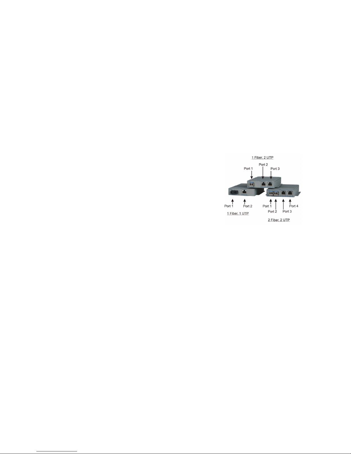
The OmniConverter GPoE/S and GPoE+/S media converters with multi-port options
provide 10/100/1000BASE-T UTP to 1000BASE-X or 100BASE-FX ber conversion
and function as Power-over-Ethernet (PoE) Power Sourcing Equipment (PSE). Port
congurations are available in single or dual UTP and SFP ports.
OmniConveter GPoE/S and GPoE+/S
Equipment that provides DC power over twisted-pair cable is known as Power
Sourcing Equipment (PSE). Equipment that is powered over twisted-pair cable is
known as a Powered Device (PD).
The OmniConverter GPoE/S supports IEEE 802.3af PoE standard providing up to
15.4W of DC power to each PD.
The OmniConverter GPoE+/S supports IEEE 802.3at PoE+ standard providing up
to 25.5W of DC power to each PD.
Installation Procedure
1) Congure DIP-switches
2) Apply AC Power
3) Apply DC Power
4) Connect Cables
5) Verify Operation
1) Congure DIP-switches
DIP-switches are located on the side of the OmniConverter module. The DIP-switches
are used to congure ports, link modes and PoE/PSE options.
Page 3
Page 3
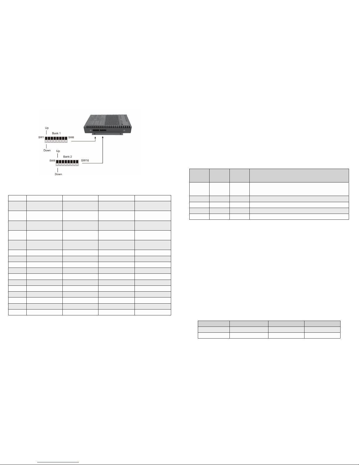
DIP-switch Bank Locations
The table below provides a description of each DIP-switch position and function.
Switch 1 Fiber, 1 UTP 1 Fiber, 2 UTP 2 Fiber, 1 UTP 2 Fiber, 2 UTP
1
Port 1 Fiber
Speed
Port 1 Fiber
Speed
Port 1 Fiber
Speed
Port 1 Fiber
Speed
2 N/A N/A
Port 2 Fiber
Speed
Port 2 Fiber
Speed
3
Port 2 UTP
AUTO/MAN
Port 2 UTP
AUTO/MAN
Port 3 UTP
AUTO/MAN
Port 3 UTP
AUTO/MAN
4
Port 2 UTP Speed
(Only in MAN mode)
Port 2 UTP Speed
(Only in MAN mode)
Port 3 UTP Speed
(Only in MAN mode)
Port 3 UTP Speed
(Only in MAN mode)
5
Port 2 UTP Duplex
(Only in MAN mode)
Port 2 UTP Duplex
(Only in MAN mode)
Port 3 UTP Duplex
(Only in MAN mode)
Port 3 UTP Duplex
(Only in MAN mode)
6 Pause Capability Pause Capability Pause Capability Pause Capability
7 UTP Port 2 PoE/PSE UTP Port 2 PoE/PSE UTP Port 3 PoE/PSE UTP Port 3 PoE/PSE
8 N/A UTP Port 3 PoE/PSE N/A UTP Port 4 PoE/PSE
9 PSE Conguration Type PSE Conguration Type PSE Conguration Type PSE Conguration Type
10 PSE Conguration Type PSE Conguration Type PSE Conguration Type PSE Conguration Type
11 N/A N/A PSE Conguration Type PSE Conguration Type
12 Link Mode Selection Link Mode Selection Link Mode Selection Link Mode Selection
13 Link Mode Selection Link Mode Selection Link Mode Selection Link Mode Selection
14 PSE Reset PSE Reset PSE Reset PSE Reset
15 N/A N/A Redundant Fiber Link Redundant Fiber Link
16 N/A N/A Return to Port 1 Return to Port 1
DIP-switch Denitions
SW1 and SW2: F/O Speed “100/1000” DIP-switch
The OmniConverter supports 1000BASE-X and 100BASE-FX SFPs. These
DIP-switches are used to congure the unit for the speed of the installed SFPs.
Setting these DIP-switches to the Down “1000” position enables the ber port to
Page 4
accept 1000BASE-X SFPs. Setting these DIP-switches to the Up “100” position
enables the ber port to accept 100BASE-FX SFPs.
When an RJ-45 transceiver is installed in a SFP receptacle or for xed ber
models, setting this DIP-switch to Up “100” position enables the port to operate at
100Mbps*.
These DIP-switches are ignored when using Omnitron branded ber SFPs. The
OmniConverter automatically congures the ber port to the correct speed.
*Special compatibility mode for the xed ber models only.
SW3, SW4 and SW5 UTP Conguration DIP-Switches
SW3
UTP
AN/Man
SW4
UTP
100/10
SW5
UTP
FDX/HDX
UTP Mode of Operation
AN 10 or 100 FDX or HDX
The UTP port is set to auto-negotiation with the following modes
advertised: 1000FDX, 1000HDX, 100FDX, 100HDX, 10FDX,
10HDX
MAN 100 FDX The UTP port is set to manual negotiation and is forced to 100FDX.
MAN 100 HDX The UTP port is set to manual negotiation and is forced to 100HDX.
MAN 10 FDX The UTP port is set to manual negotiation and is forced to 10FDX.
MAN 10 HDX The UTP port is set to manual negotiation and is forced to 10HDX.
UTP Port Conguration Matrix
SW6 - Pause “On/Off” DIP-Switch
In auto-negotiation mode, setting this DIP-switch to the Up “On” position allows the
unit to advertise Symmetrical and Asymmetrical Pause capability. In auto-negotiation
mode, setting the DIP-switch to the Down “Off” position allows the unit to advertise
no Pause capability. In the manual mode, this DIP-switch determines the Pause
behavior.
SW7 - Power Sourcing Function, UTP Port
The OmniConverter automatically detects the attached PD and provides the
equipment with the necessary power.
This DIP-switch controls the power sourcing function for Port 2 on the single-ber
models and Port 3 on all other models (see DIP-switch Denition table on page
4). When this DIP-switch in the Down “On” position, the power sourcing function
is enabled. When the DIP-switch is in the Up “Off” position, the power sourcing
function is disabled.
Switch Position Description DOWN UP
7 UTP Port 2 or 3 PoE/PSE Enabled (ON) Disabled (OFF)
8 UTP Port 3 or 4 PoE/PSE Enabled (ON) Disabled (OFF)
Power Sourcing Function
Page 5
Page 4

SW8 - Power Sourcing Function, UTP Port
This DIP-switch controls the power sourcing function for the 2nd UTP port on the
2 UTP port models (see DIP-switch Denition table on page 4). When this DIP-
switch in the Down “On” position, the power sourcing function is enabled. When the
DIP-switch is in the “Off” UP position, the power sourcing function is disabled.
SW9, SW10 and SW11 - Power Sourcing Options
The UTP ports can be congured to support different powering options. The
powering options include Alternative A (supporting power on pins 1,2 and 3,6),
Alternative B (supporting power on pins 4,5 and 7,8), legacy Power Devices (PDs)
that use large capacitance for detection (supporting pins 4,5 and 7,8) and legacy
VoIP phones (supporting reverse polarity on pins 4,5 and 7,8).
SW9 SW10 SW11
PoE Option for
1 Fiber 1 UTP (UTP Port 2)
or
2 Fiber 1UTP (UTP Port 3)
DOWN DOWN N/A IEEE Alternative A (Alt A)
UP DOWN N/A IEEE Alternative B (Alt B)
DOWN UP N/A Large Capacitor Detection
UP UP N/A Legacy VoIP Phones
Power Sourcing Options for Models with 1 UTP Port
SW9 SW10 SW11
PoE Option for
1 Fiber 2 UTP
PoE Option for
2 Fiber 2 UTP
Port 2 Port 3 Port 3 Port 4
DOWN DOWN DOWN IEEE Alt A IEEE Alt A IEEE Alt A IEEE Alt A
DOWN DOWN UP IEEE Alt A IEEE Alt B IEEE Alt A IEEE Alt B
DOWN UP DOWN IEEE Alt B IEEE Alt A IEEE Alt B IEEE Alt A
DOWN UP UP IEEE Alt B Legacy VoIP IEEE Alt B Legacy VoIP
UP DOWN DOWN
Large Capacitor
Detection
IEEE Alt A
Large Capacitor
Detection
IEEE Alt A
UP DOWN UP
Large Capacitor
Detection
IEEE Alt B
Large Capacitor
Detection
IEEE Alt B
DOWN UP UP Legacy VoIP IEEE Alt A Legacy VoIP IEEE Alt A
UP UP UP Legacy VoIP Legacy VoIP Legacy VoIP Legacy VoIP
Power Sourcing Options for Models with 2 UTP Ports
Page 6
Select the appropriate powering source option based on the PD type. Use the
following table to determine the compatibility of the PD.
PD Type
PSE Type
Alternative A Alternative B Large Capacitor Legacy VoIP (Cisco)
IEEE 802.3 af Yes Yes Yes No
IEEE 802.3 at* Yes Yes Yes No
Legacy VoIP Phones No No No Yes
Large Capacitor No No Yes No
*Requires GPoE+/S models
Power Sourcing Compatibility
RJ-45 Pinout
PoE Option
Alternative A Alternative B Legacy VoIP
1 Vport Positive
2 Vport Positive
3 Vport Negative
4 Vport Positive Vport Negative
5 Vport Positive Vport Negative
6 Vport Negative
7 Vport Negative Vport Positive
8 Vport Negative Vport Positive
Voltage Polarity for PoE Options
NOTE: Alternative A and Alternative B pinouts are compliant with IEEE802.3af and
IEEE802.3at specications. Power is applied to center tap of transformers for both
Alternative A and Alternative B pinouts per IEEE802.3at. Power is applied to center
tap of transformers for Legacy VoIP pinout, but polarity is reversed.
SW12 and SW13 - Link Modes
The OmniConverter supports Link Segment and Asymmetrical Link Propagate. See
Appendix A for Link Mode block diagrams.
Link Segment
In Link Segment mode, all ports operate independently. A loss of a receive link
signal will only affect the port detecting the loss of signal. All the other ports will
continue to generate a link signal. A loss of link on the UTP port will only affect the
UTP port, and the other ports will remain unaffected.
Asymmetrical Link Propagate
In Asymmetrical Link Propagate mode, faults are propagated based on the port
notation. Port 1 to Port 2 notation indicates the direction the loss of link signal will
propagate. A loss of receive link on the ber optic Port 1 causes the UTP Port 2 to
drop its link due to the propagated state (Port 1 to Port 2). The loss of link on the
Page 7
Page 5

UTP Port 2 does not cause the loss of link to propagate. The loss only propagates
in the Port 1 to Port 2 direction. See Port Congurations on Page 3.
Note: A loss of link or loss of signal is when the optical receiver on the media converter
can no longer detect the presence of an optic signal.
Note: On models with 2 ber ports or 2 UTP ports, both ports of the same media type
must be in link fault condition before the fault will propagate.
SW12 SW13 Function
DOWN DOWN Link Segment (LS)
UP DOWN
Asymmetrical Link Propagate Port 1 to Port 2 (1+1 - 2 Port models),
Port 1 to Port 2 and Port 3 (1+2 - 3 Port models),
Port 1 and Port 2 to Port 3 (2+1 - 3 Port models) and
Port 1 and Port 2 to Port 3 and Port 4 (2+2 - 4 Port models).
DOWN UP
Asymmetrical Link Propagate Port 2 to Port 1 (1+1 - 2 Port models),
Port 2 and Port 3 to Port 1 (1+2 - 3 Port models)
Port 3 to Port 1 and Port 2 (2+1 - 3 Port models)
and Port 3 and Port 4 to Port 1 and Port 2 (2+2 - 4 Port models)
UP UP Invalid Conguration
Link Modes
SW14 - Power Sourcing Reset
The OmniConverter can be congured to disable (reset) the PoE output power for 2
seconds after a loss of receive link on any ber port. This feature is typically used
to allow a PD to re-initialize after a failure on the incoming ber. When this DIP-
switch is in the Up “Lk Loss” position, the module will disable PoE output power for
2 seconds following a loss of receive link on any ber port. When this DIP-switch
is in the Down position, PoE output power does not reset on ber link loss.
SW15 and SW16 - Port Redundant Mode
SW15 and SW16 are valid on models with 2 ber ports only. Port redundancy is
available when connected to another Omnitron device with 2 ber ports that supports
port redundancy.
SW15 controls the port redundancy mode of the module. When SW15 is in the Down
“Off” (default) position, the ber ports operate in a non-redundant (independent)
mode. When SW15 is in the Up “On” position, the ber ports operate as redundant
links. A fault on the primary ber port (Port 1), will cause a fail over to the secondary
ber port (Port 2) within 50msec.
SW16 enables the module to return to the primary ber port (Port 1) after the ber
link has been restored for 6 seconds. When SW16 is in the Down “Off” position,
return to primary is disabled (inactive). When the SW16 is in the Up “On” position,
return to primary is enabled.
Page 8
Switch 15
P1+P2 Redun
Switch 16
Rtn P1
Function
DOWN (Off) DOWN (Off) Non-redundant mode - normal mode
DOWN (Off) UP (On) Non-redundant mode - normal mode
UP (On) DOWN (Off) Redundant mode - no return to primary
UP (On) UP (On) Redundant mode - return to primary
Port Redundancy Modes
2) Apply AC Power
To power the unit using the AC/DC adapter, connect the AC/DC adapter to the
AC outlet. Route the power cord through the provided strain relief for additional
support. Then connect the barrel plug at the end of the wire on the AC/DC adapter
to the 2.1mm DC barrel connector (center-positive) on the unit. Conrm that the
unit has powered up properly by checking the Power LED located on the front of
the installed module.
Installation of the equipment should be such that the air ow in the front, back, side
and top vents of the chassis are not compromised or restricted.
If the installation requires NEBS grounding, secure the grounding wire to the ground
lug. See the gure below for the location of the grounding lug.
Rear View with AC Power Connector
NEVER ATTEMPT TO OPEN THE CHASSIS OR
SERVICE THE POWER SUPPLY. OPENING THE
CHASSIS MAY CAUSE SERIOUS INJURYOR DEATH.
THERE ARE NO USER REPLACEABLE OR
SERVICEABLE PARTS IN THIS UNIT.
WARNING!!!
Page 9
Page 6

Connect the power wires to the circuit breaker and switch the circuit breaker
ON. If any modules are installed, their Power LED should indicate the presence
of power.
Installation of the equipment should be such that the air ow in the front, back,
side and top vents of the chassis are not compromised or restricted.
If the installation requires NEBS grounding, secure the grounding wire to the
ground lug. See the gure below for the location of the grounding lug.
Rear View with DC Power Connector
NEVER ATTEMPT TO OPEN THE CHASSIS OR
SERVICE THE POWER SUPPLY. OPENING THE
CHASSIS MAY CAUSE SERIOUS INJURYOR DEATH.
THERE ARE NO USER REPLACEABLE OR
SERVICEABLE PARTS IN THIS UNIT.
WARNING!!!
Page 11
3) Apply DC Power
Power source should be available within 5 ft. of the chassis. The over current
protection for connection with centralized DC shall be provided in the building
installation, and shall be a UL listed circuit breaker rated 20 Amps, and installed
per the National Electrical Code, ANSI/NFPA-70.
If PoE, this equipment requires 46 to 57VDC @ 1.5Amp max rated power. If
PoE+, this equipment requires 52 to 57VDC @ 1.5Amp max rated power (see
Specication table for specic model requirements). Appropriate overloading
protection should be provided on the DC power source outlets utilized.
WARNING: OnlyaDC power source that complies with
safety extra low voltage (SELV) requirements can be
connected to the DC-input power supply.
WARNING REGARDING EARTHING GROUND:
o
o
o
o
This equipment shall be connected to the DC supply
system earthing electrode conductor or to a bonding
jumper from an earthing terminal bar or bus to which the
DC supply system earthing electrode is connected.
This equipment shall be located in the same immediate
area (such as adjacent cabinets) as any other equipment
that has a connection between the earthed conductor of
the same DC supply circuit and the earthing conductor,
and also the point of earthing of the DC system. The DC
system shall not be earthed elsewhere.
The DC supply source is to be located within the same
premises as this equipment.
There shall be no switching or disconnecting devices in
the earthed circuit conductor between the DC source and
the earthing electrode conductor.
Locate the DC circuit breaker of the external power source, and switch the
circuit breaker to the OFF position.
Prepare a power cable using a three conductor insulated wire (not supplied)
with a 14 AWG gauge minimum. Cut the power cable to the length required.
Strip approximately 3/8 of an inch of insulation from the power cable wires.
Route the power cables through the provided strain relief for additional support.
Connect the power cables to the OmniConverter by fastening the stripped ends
to the DC power connector.
WARNING: Note the wire colors used in making the positive, negative and
ground connections. Use the same color assignment for the connection at the
circuit breaker.
Page 10
Page 7

4) Connect Cables
a. When using the SFP model, insert the SFP Fiber transceiver into the SFP
receptacle on the front of the module (see the SFP Data Sheet 091-17000-001
for supported Gigabit and Fast Ethernet transceivers).
NOTE: The release latch of the SFP Fiber transceiver must be in the closed
(up) position before insertion.
b. Connect an appropriate multimode or single-mode ber cable to the ber port
on the front of the module. It is important to ensure that the transmit (TX) is
attached to the receive side of the device at the other end and the receive
(RX) is attached to the transmit side. When using single-ber (SF) models, the
TX wavelength must match the RX wavelength at the other end and the RX
wavelength must match the TX wavelength at the other end.
c. Connect the Ethernet 10/100/1000 UTP port via a Category 5 or better cable
to an external 10BASE-T, 100BASE-TX or 1000BASE-T Ethernet device.
Page 12
5) Verify Operation
Verify the OmniConverter is operational by viewing the LED indicators.
Power LED Indicators
Legend Indicator Description
Pwr
OFF Unit not powered
Green - ON Unit powered
Amber - ON Over temperature condition
Power LED Indicators
Fiber Port LED Indicators
Legend Indicator Description
100
OFF No link
Green - ON Port linked at 100Mbps
Green - Blinking at 10Hz Port data activity at 100Mbps
Green - Blinking at 1Hz Port linked at 100Mbps and in redundant standby mode
Amber - Blinking at 1Hz
Port linked at 100Mbps and receiving Far End Fault Indicator
(FEFI)
1000
OFF No link
Green - ON Port linked at 1000Mbps
Green - Blinking at 10Hz Port data activity at 1000Mbps
Green - Blinking at 1Hz Port linked at 1000Mbps and in redundant standby mode
Amber - Blinking at 1Hz Port linked at 1000Mbps and receiving AN Remote Fault
10
(100+1000)
OFF No link
Green - ON Port linked at 10Mbps
Green - Blinking at 10Hz Port data activity at 10Mbps
Green - Blinking at 1Hz Port linked at 10Mbps and in redundant standby mode
Stat
OFF
Transceiver does not support digital diagnostics or no
transceiver (SFP) is installed
Green - ON
Transceiver (SFP) supports digital diagnostics and no alarm is
detected
Amber - ON
Transceiver (SFP) supports digital diagnostics and alarms are
present
Fiber LED Indicators
Page 13
Page 8

UTP Port Indicators
Legend Indicator Description
100
OFF No link
Green - ON Port linked at 100Mbps
Green - Blinking at 10Hz Port data activity at 100Mbps
1000
OFF No link
Green - ON Port linked at 1000Mbps
Green - Blinking at 10Hz Port data activity at 1000Mbps
10
(100+1000)
OFF No link
Green - ON Port linked at 10Mbps
Green - Blinking at 10Hz Port data activity at 10Mbps
Amber - Blinking at 1Hz Port linked at 10Mbps and receiving AN Remote Fault
FDX
Green - ON
Port is congured for full-duplex via DIP-switch or has
negotiated to full-duplex in AN mode
OFF
Port is congured for half-duplex via DIP-switches or Port 2 has
negotiated to half-duplex in AN mode or Port 2 in AN mode has
not established the correct connection
PSE
Green - ON Port PSE is active
Amber - ON Port PSE inactive
Amber - Blinking at 1Hz
Port PSE inactive due to resistance too low (< 15k ohms) or
short circuit detected
Amber - Blinking at 10Hz Port PSE inactive due to resistance to high (33k to 500k ohms)
OFF Port PSE disabled
UTP LED Indicators
Page 14 Page 15
Specications
Model Type
OmniConverter GPoE/S
Standard (PoE) IEEE 802.3af
Max PoE Power
(per UTP port)
15.4W
Protocols (Ethernet)
Fiber:
UTP Copper:
100BASE-FX, 1000BASE-X
10/100/1000BASE-T
Copper Connectors RJ-45
Fiber Connectors
SFP:
Dual Fiber:
Single-Fiber:
LC
SC, ST
SC
AC Power requirements
(typical)
100 to 240VAC / 50 to 60Hz
350mA@120VAC
DC Power requirements
(typical)
+/- 46 to 57VDC
800mA
Dimensions W: 4.5” x D: 6.0” x H 1.0”
Weight 1.07 lbs.
Compliance* UL, CE, FCC Class A
Temperature
Standard Operating:
Wide Operating:
Extended Operating:
Storage:
0 to 50º C
-40 to 60º C
-40 to 75º C
-40 to 80º C
Humidity 5 to 95% (non-condensing)
Altitude -100m to 4000m
MTBF (hrs)
AC Model:
DC Model:
183,000 hrs.
474,000 hrs.
*Pending
Page 9

Model Type
OmniConverter GPoE+/S
Standard (PoE) IEEE 802.3at
Max PoE Power
(per UTP port)
25.5W
Protocols (Ethernet)
Fiber:
UTP Copper:
100BASE-FX, 1000BASE-X
10/100/1000BASE-T
Copper Connectors RJ-45
Fiber Connectors
SFP:
Dual Fiber:
Single-Fiber:
LC
SC, ST
SC
AC Power requirements
(typical)
100 to 240VAC / 50 to 60HZ
460mA@120VAC
DC Power requirements
(typical)
+/- 52 to 57VDC
1.2A
Dimensions W: 4.5” x D: 6.0” x H 1.0”
Weight 1.07 lbs.
Compliance* UL, CE, FCC Class A
Temperature
Standard Operating:
Wide Operating:
Extended Operating:
Storage:
0 to 50º C
-40 to 60º C
-40 to 75º C
-40 to 80º C
Humidity 5 to 95% (non-condensing)
Altitude -100m to 4000m
MTBF (hrs)
AC Model:
DC Model:
83,000 hrs.
474,000 hrs.
Appendix A: Link Modes
Page 16 Page 17
*Pending
Page 10

Page 18 Page 19
Customer Support Information
If you encounter problems while installing this product, contact Omnitron Technical
Support:
Phone: (949) 250-6510
Fax: (949) 250-6514
Address: Omnitron Systems Technology, Inc.
140 Technology Dr., #500
Irvine, CA 92618, USA
Email: support@omnitron-systems.com
URL: www.omnitron-systems.com
040-09400-001D 12/10
 Loading...