

Page 1
OmniConverter
GHPoE/S
User Manual
Warranty
This product is warranted to the original purchaser against defects in material and
workmanship for a period of two (2) years from the date of shipment. A LIFETIME
warranty may be obtained by the original purchaser by registering this product within
ninety (90) days from the date of shipment at www.omnitron-systems.com/support.
During the warranty period, Omnitron will, at its option, repair or replace a product
which is proven to be defective with the same product or with a product with at least
the same functionality.
For warranty service, the product must be sent to an Omnitron designated facility, at
Buyer’s expense. Omnitron will pay the shipping charge to return the product to Buyer’s
designated US address using Omnitron’s standard shipping method.
Limitation of Warranty
The foregoing warranty shall not apply to defects resulting from improper or inadequate
®
use and/or maintenance of the equipment by Buyer, Buyer-supplied equipment, Buyer-
supplied interfacing, unauthorized modications or tampering with equipment (including
removal of equipment cover by personnel not specically authorized and certied by
Omnitron), or misuse, or operating outside the environmental specication of the product
(including but not limited to voltage, ambient temperature, radiation, unusual dust, etc.),
or improper site preparation or maintenance.
No other warranty is expressed or implied. Omnitron specically disclaims the implied
warranties of merchantability and tness for any particular purpose.
The remedies provided herein are the Buyer’s sole and exclusive remedies. Omnitron
shall not be liable for any direct, indirect, special, incidental, or consequential damages,
whether based on contract, tort, or any legal theory.
Environmental Notices
The equipment covered by this manual must be disposed of or recycled in accordance
with the Waste Electrical and Electronic Equipment Directive (WEEE Directive) of
the European Community directive 2012/19/EU on waste electrical and electronic
equipment (WEEE) which, together with the RoHS Directive 2011/65/EU, for electrical
and electronic equipment sold in the EU after July 1, 2006. Such disposal must follow
national legislation for IT and Telecommunication equipment in accordance with the
WEEE directive: (a) Do not dispose waste equipment with unsorted municipal and
household waste. (b) Collect equipment waste separately. (c) Return equipment using
collection method agreed with Omnitron.
The equipment is marked with the WEEE symbol shown to indicate that it must be
collected separately from other types of waste. In case of small items the symbol may
be printed only on the packaging or in this manual. If you have questions regarding
the correct disposal of equipment go to www.omniton-systems.com/support or e-mail
to Omnitron at intlinfo@omnitron-systems.com.
38 Tesla, Irvine, CA 92618 USA
Phone: (949) 250-6510; Fax: (949) 250-6514
©2019 Omnitron Systems Technology, Inc.
Page 2
Page 2
OmniConverter® GHPoE/S
User Manual
PRODUCT OVERVIEW
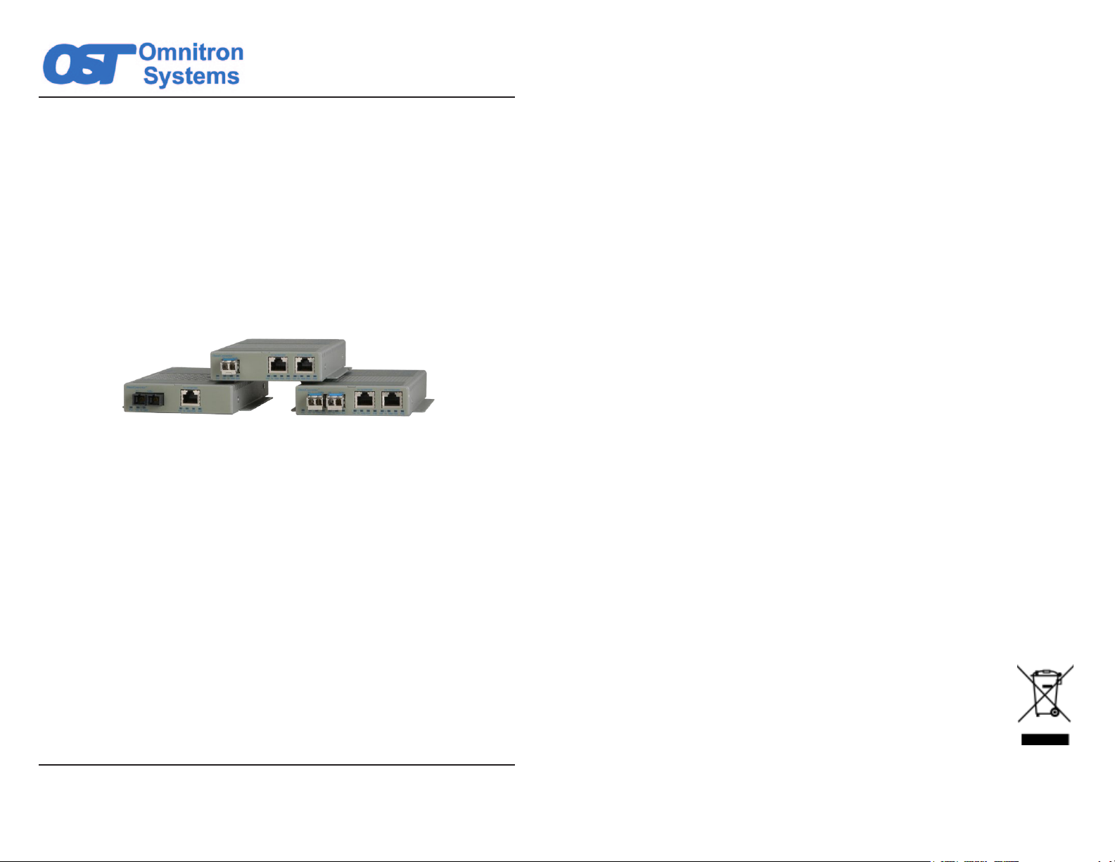
The OmniConverter GHPoE/S is a multi-port media converter that converts
10/100/1000BASE-T copper to 1000BASE-X or 100BASE-X ber and supports Power
over Ethernet up to 60 watts. Classied as Power Sourcing Equipment (PSE), the
GHPoE/S can provide power to one or two Powered Devices (PDs) using standard
UTP cables that carry the Ethernet data.
The main function of the PSE is to automatically detect a PD, classify the PD and supply
power to the link (only if a PD is detected). The PSE detects a PD by applying a low
voltage on the cable and then looks for a signature from the attached PD. A compliant
PD is required to have the valid signature. Classication of the PD is done to determine
the maximum power levels required by the PD. After the PD is classied, the PSE will
allow the PD to draw power up to the maximum classication level.
The GHPoE/S automatically preforms the detection, classication and powering
functions. It supports IEEE 802.3af PoE (15W) and IEEE 802.3at PoE+ (30W) standard.
It can also provide up to 60W PoE per RJ-45 port for latest high-power outdoor PDs
such as cameras and Wi-Fi access points.
Installation Procedure
1) Congure DIP-switches
2) Apply AC Power
3) Apply DC Power
4) Connect Cables
5) Verify Operation
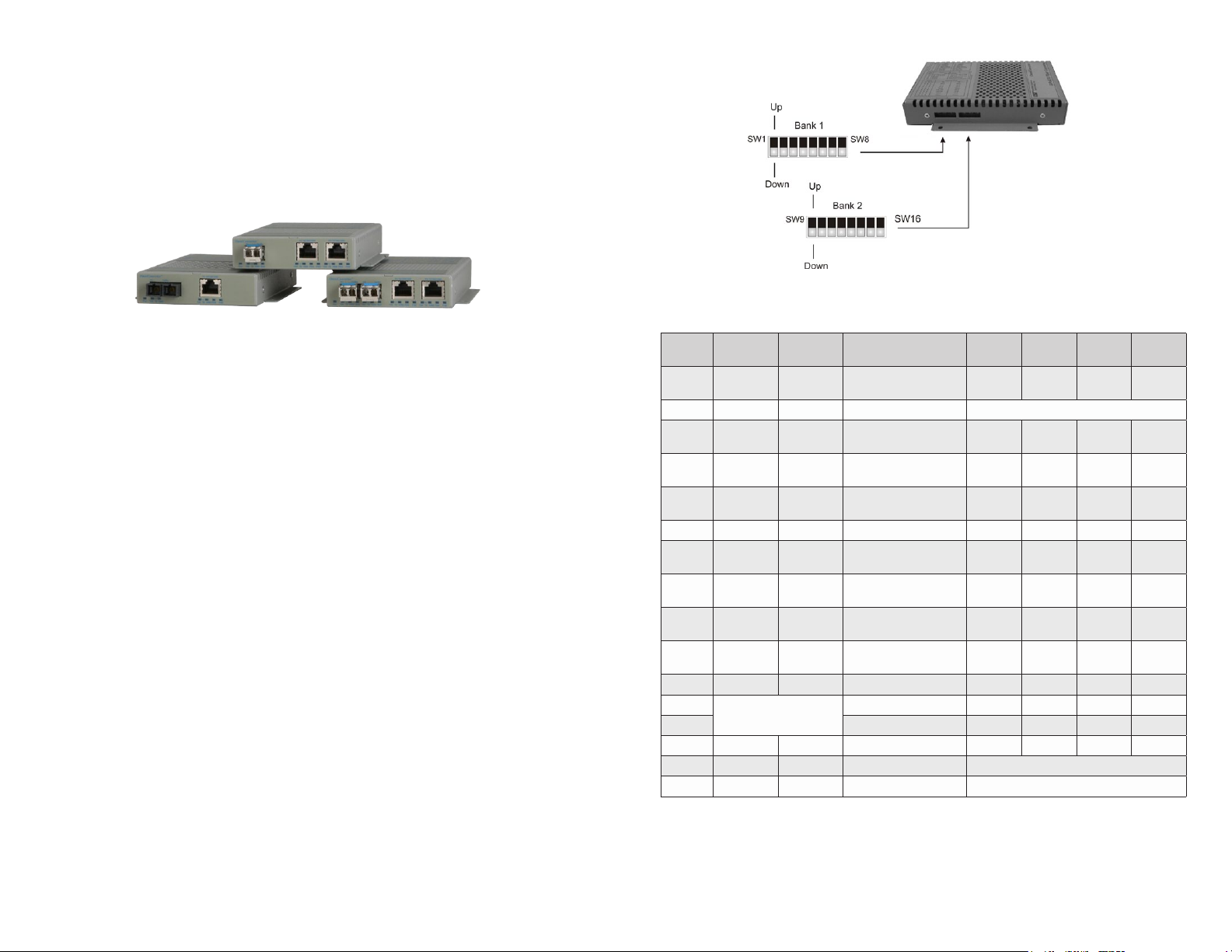
1) Congure DIP-switches
DIP-switches are located on the side of the OmniConverter module. The DIP-switches
are used to congure ports, link modes and PoE/PSE options.
DIP-switch Bank Locations
The table below provides a description of each DIP-switch position and function.
Switch DOWN UP Function
1 Auto
2 N/A N/A N/A N/A
3 Auto Man
4 100 10
5 FDX HDX
6 Off On Pause Capability x x x x
7 Enabled Disabled
8 Enabled Disabled
9 Normal Forced On
10 Normal Forced On
11 On Off MAC Learning N/A x N/A x
12
13 Link Mode Selection x x x x
14 Off On PSE Reset x x x x
15 N/A N/A N/A N/A
16 N/A N/A N/A N/A
See DIP-switch
Forced
100M
Description
Port 1
Fiber Speed
Port 2
Auto/Manual
Port 2 Speed
(Only in MAN mode)
Port 2 Duplex
(Only in MAN mode)
Port 2
PSE Power
Port 3
PSE Power
Port 2
PSE Power Override
Port 3
PSE Power Override
Link Mode Selection x x x x
1 FF
1 RJ-45
N/A x N/A x
N/A x N/A x
1 FF
2 RJ-45
x x x x
x x x x
x x x x
x x x x
x x x x
x x x x
1 SFP
1 RJ-45
2 RJ-45
1 SFP
Page 3
DIP-switch Denitions for Models with 1 Fiber Port
Page 4
Page 3

Switch DOWN UP Function
1 Auto
2 Auto
3 Auto Man
4 100 10
5 FDX HDX
6 Off On Pause Capability x x x x
7 Enabled Disabled
8 Enabled Disabled
9 Normal Forced On
10 Normal Forced On
11 On Off MAC Learning x x x x
12
13 Link Mode Selection x x x x
14 Off On PSE Reset x x x x
15 Off On Redundant Fiber Link x x x x
16 Off On Return to Port 1 x x x x
See DIP-switch
Forced
100M
Forced
100M
Description
Port 1
Fiber Speed
Port 2
Fiber Speed
Port 3
Auto/Manual
Port 3 Speed
(Only in MAN mode)
Port 3 Duplex
(Only in MAN mode)
Port 3
PSE Power
Port 4
PSE Power
Port 3
PSE Power Override
Port 4
PSE Power Override
Link Mode Selection x x x x
2 FF
1 RJ-45
N/A x N/A x
N/A x N/A x
2 FF
2 RJ-45
x x x x
x x x x
x x x x
x x x x
x x x x
x x x x
x x x x
2 SFP
1 RJ-45
2 SFP
2 RJ-45
DIP-switch Denitions for Models with 2 Fiber Port
SW1 and SW2: F/O Speed “100/1000”
These DIP-switches congure the speed of the transceivers installed in the SFP ports. If
these DIP-switches are in the Down (default) position, the ports will automatically detect
the data rate of the transceivers installed and operate at 100M or 1000M accordingly.
If these DIP-switches are in the UP position, a 100M capable transceivers must be
installed in the SFP ports.
When an RJ-45 transceiver is installed in a SFP receptacle or for xed ber models,
setting this DIP-switch to Up “100” position enables the port to operate at 100Mbps*.
*Special compatibility mode for the xed ber models only.
SW3, SW4 and SW5: RJ-45 Conguration
These DIP-switches congure the rst RJ-45 port on the module (Port 2 on a single ber
model and Port 3 on a dual ber model). The second RJ-45 port is always congured
for auto-negotiation.
When DIP-switch SW3 is in the Down “AN” position, SW4 and SW5 are ignored.
SW3
RJ-45
AN/Man
AN 10 or 100 FDX or HDX
MAN 100 FDX The RJ-45 port is set to manual negotiation and is forced to 100FDX.
MAN 100 HDX The RJ-45 port is set to manual negotiation and is forced to 100HDX.
MAN 10 FDX The RJ-45 port is set to manual negotiation and is forced to 10FDX.
MAN 10 HDX The RJ-45 port is set to manual negotiation and is forced to 10HDX.
SW4
RJ-45
100/10
SW5
RJ-45
FDX/HDX
Mode of Operation
The RJ-45 port is set to auto-negotiation with the following modes
advertised: 1000FDX, 1000HDX, 100FDX, 100HDX, 10FDX,
10HDX
RJ-45 Port Conguration Matrix
SW6: Pause “On/Off”
In auto-negotiation mode, setting this DIP-switch to the Up “On” position allows the
unit to advertise Symmetrical and Asymmetrical Pause capability. In auto-negotiation
mode, setting the DIP-switch to the Down “Off” position allows the unit to advertise no
Pause capability. In the manual mode, this DIP-switch determines the Symmetrical
Pause behavior of the ports.
SW7: Power Sourcing “Enable/Disable”, RJ-45 Port
The OmniConverter automatically detects the attached PD and provides the equipment
with the necessary power.
This DIP-switch controls the power sourcing for rst RJ-45 port on the module (Port 2
on the single ber models and Port 3 on dual ber models). When this DIP-switch in
the Down “On” position, the power sourcing is enabled. When the DIP-switch is in the
Up “Off” position, the power sourcing is disabled.
SW8: Power Sourcing “Enable/Disable”, RJ-45 Port
This DIP-switch controls the power sourcing for the second RJ-45 port on the module
(Port 3 on the single ber models and Port 4 on dual ber models). When this DIP-
switch in the Down “On” position, the power sourcing is enabled. When the DIP-switch
is in the Up “Off” position, the power sourcing is disabled.
SW9, SW10 “Normal/Forced” PoE Power Mode
This DIP-switch allows the PoE power to be forced ON when connected to a PD with
non-standard detection characteristics.
DIP-switch SW9 controls the forced capability for the rst RJ-45 port on the module
(Port 2 on the single ber models and Port 3 on dual ber models) and SW10 controls
the forced capability for the second RJ-45 port on the module (Port 3 on the single ber
models and Port 4 on dual ber models).
When these DIP-switches are in the Down “Normal” position, the port will automatically
preform the detection, classication and powering functions for the attached PD. When
these DIP-switches are in the Up “Forced” position, a maximum of 60 watts of power
will be available to the PD.
SW11: MAC Learning “On/Off”
When this DIP-switch is in the Down “On” position, all ports on the module will learn the
source MAC address of each received packet and store the address so packets destined
for the stored addresses can be forwarded to the appropriate interface on the module.
Page 5
Page 6
Page 4

When the DIP-switch is in the Up “Off” position, learning is turned off and all received
packets are forwarded to all ports.
Models with one ber port and one copper port have MAC learning disabled.
SW12 and SW13: Link Modes
The OmniConverter supports Link Segment and Asymmetrical Link Propagate.
Link Segment
In Link Segment mode, all ports operate independently. A loss of a receive link signal
will only affect the port detecting the loss of signal. All the other ports will continue to
generate a link signal. A loss of link on the RJ-45 port will only affect the RJ-45 port,
and the other ports will remain unaffected.
Asymmetrical Link Propagate
In Asymmetrical Link Propagate mode, faults are propagated based on the port notation.
Port 1 to Port 2 notation indicates the direction the loss of link signal will propagate.
A loss of receive link on the ber optic Port 1 causes the RJ-45 Port 2 to drop its link
due to the propagated state (Port 1 to Port 2). The loss of link on the RJ-45 Port 2
does not cause the loss of link to propagate. The loss only propagates in the Port 1 to
Port 2 direction.
Note: A loss of link or loss of signal is when the optical receiver on the media
converter can no longer detect the presence of an optic signal.
Note: On models with 2 ber ports or 2 RJ-45 ports, both ports of the same media
type must be in link fault condition before the fault will propagate.
SW12 SW13 Function
DOWN DOWN Link Segment (LS)
Asymmetrical Link Propagate Port 1 to Port 2 (1+1 - 2 Port models),
UP DOWN
DOWN UP
UP UP Invalid Conguration
Port 1 to Port 2 and Port 3 (1+2 - 3 Port models),
Port 1 and Port 2 to Port 3 (2+1 - 3 Port models) and
Port 1 and Port 2 to Port 3 and Port 4 (2+2 - 4 Port models).
Asymmetrical Link Propagate Port 2 to Port 1 (1+1 - 2 Port models),
Port 2 and Port 3 to Port 1 (1+2 - 3 Port models)
Port 3 to Port 1 and Port 2 (2+1 - 3 Port models)
and Port 3 and Port 4 to Port 1 and Port 2 (2+2 - 4 Port models)
SW15 controls the port redundancy mode of the module. When SW15 is in the Down
“Off” (default) position, the ber ports operate in a non-redundant (independent) mode.
When SW15 is in the Up “On” position, the ber ports operate as redundant links. A
fault on the primary ber port (Port 1), will cause a fail over to the secondary ber port
(Port 2) within 50msec.
SW16: Return to P1 “Off/On”
SW16 is only valid on models with 2 ber ports.
SW16 enables the module to return to the primary ber port (Port 1) after the ber link
has been restored and stable for 6 seconds. When SW16 is in the Down “Off” position,
return to primary is disabled (inactive). When the SW16 is in the Up “On” position,
return to primary is enabled.
When SW15 is in the Down “Off” position, SW16 is ignored.
Switch 15
P1+P2 Redun
DOWN (Off) DOWN (Off) Non-redundant mode - normal mode
DOWN (Off) UP (On) Non-redundant mode - normal mode
UP (On) DOWN (Off) Redundant mode - no return to primary
UP (On) UP (On) Redundant mode - return to primary
Switch 16
Rtn P1
Function
Port Redundancy Modes
2) APPLY AC POWER
To power the unit using the AC/DC adapter, connect the DC plug at the end of the
wire on the AC/DC adapter to the DC connector on the unit. Then connect the AC/DC
adapter to the AC outlet. Conrm that the unit has powered up properly by checking
the Power LED located on the front of the installed module.
Installation of the equipment should be such that the air ow in the front, back, side
and top vents of the chassis are not compromised or restricted.
If the installation requires grounding, secure the grounding wire to the ground screw.
See the gure below for the location of the grounding screw.
Link Modes
SW14: Power Sourcing Reset “Off/Reset”
The OmniConverter can be congured to reset the PoE output power for 2 seconds
after a loss of receive link on any ber port. This feature is typically used to allow a PD
to re-initialize after a failure on the incoming ber.
When this DIP-switch is in the Up “Reset” position, the module will disable PoE output
power for 2 seconds following a loss of receive link on any ber port. When this DIPswitch is in the Down “Off” position, PoE output power does not reset on ber link loss.
SW15: Link Redundant “Off/On”
SW15 is only valid on models with 2 ber ports. Port redundancy is available when
connected to Omnitron and third party devices with 2 ber ports.
Page 7
Rear View with AC Power Connector
Page 8
Page 5

WARNING!!!
WARNING REGARDING EARTHING GROUND:
o
o
o
o
This equipment shall be connected to the DC supply
system earthing electrode conductor or to a bonding
jumper from an earthing terminal bar or bus to which the
DC supply system earthing electrode is connected.
This equipment shall be located in the same immediate
area (such as adjacent cabinets) as any other equipment
that has a connection between the earthed conductor of
the same DC supply circuit and the earthing conductor,
and also the point of earthing of the DC system. The DC
system shall not be earthed elsewhere.
The DC supply source is to be located within the same
premises as this equipment.
There shall be no switching or disconnecting devices in
the earthed circuit conductor between the DC source and
the earthing electrode conductor.
NEVER ATTEMPT TO OPEN THE CHASSIS OR
SERVICE THE POWER SUPPLY. OPENING THE
CHASSIS MAY CAUSE SERIOUS INJURYOR DEATH.
THERE ARE NO USER REPLACEABLE OR
SERVICEABLE PARTS IN THIS UNIT.
3) APPLY DC POWER
A power source should be available within 5 ft. of the chassis. The over current protection
for connection with centralized DC shall be provided in the building installation, and shall
be a UL listed circuit breaker rated 20 Amps, and installed per the National Electrical
Code, ANSI/NFPA-70.
The GHPoE requires 48 to 57VDC @ 2.27 Amp max rated power when powering two
60W PoE PDs. Appropriate overloading protection should be provided on the DC
power source outlets utilized.
WARNING: OnlyaDC power source that complies with
safety extra low voltage (SELV) requirements can be
connected to the DC-input power supply.
WARNING: Note the wire colors used in making the positive, negative and ground
connections. Use the same color assignment for the connection at the circuit
breaker.
Connect the power wires to the circuit breaker and switch the circuit breaker ON. If any
modules are installed, the Power LED should indicate the presence of power.
Installation of the equipment should be such that the air ow in the front, back, side
and top vents of the chassis are not compromised or restricted.
If the installation requires grounding, secure the grounding wire to the ground screw.
See the gure below for the location of the grounding screw.
Rear View with DC Terminal Connector
WARNING!!!
NEVER ATTEMPT TO OPEN THE CHASSIS OR
SERVICE THE POWER SUPPLY. OPENING THE
CHASSIS MAY CAUSE SERIOUS INJURYOR DEATH.
THERE ARE NO USER REPLACEABLE OR
SERVICEABLE PARTS IN THIS UNIT.
Locate the DC circuit breaker of the external power source, and switch the circuit
breaker to the OFF position.
Prepare a power cable using a three conductor insulated wire (not supplied) with a 14
AWG gauge minimum. Cut the power cable to the length required.
Strip approximately 3/8 of an inch of insulation from the power cable wires.
Connect the power cables to the terminal by fastening the stripped ends to the DC
power connector.
Page 9
4) CONNECT CABLES
a. When using the SFP model, insert the SFP Fiber transceiver into the SFP receptacle
on the front of the module.
NOTE: The release latch of the SFP Fiber transceiver must be in the closed
(up) position before insertion.
b. Connect an appropriate multimode or single-mode ber cable to the ber port on
the front of the module. It is important to ensure that the transmit (TX) is attached
to the receive side of the module at the other end and the receive (RX) is attached
to the transmit side. When using single-ber (SF) models, the TX wavelength must
match the RX wavelength at the other end and the RX wavelength must match the
TX wavelength at the other end.
c. Connect the Ethernet 10/100/1000 RJ-45 port via a Category 5 or better cable to
an external 10BASE-T, 100BASE-TX or 1000BASE-T Ethernet device.
Page 10
Page 6

5) VERIFY OPERATION
Once the module has been installed and congured per steps 1 - 4, verify the module
is operational by viewing the LED indicators.
The Power LED indicates the module is receiving power.
The Fiber Optic LEDs indicates the ber optic connection has been established.
The RJ-45 10/100/1000 LEDs indicate the speed of the UTP connection.
The PSE LED indicates the module has established a successful detection of a PD
and is supplying Power over Ethernet.
Power LED Indicators
Legend Indicator Description
OFF Unit not powered
Pwr
Green - ON Unit powered
Amber - ON Over temperature condition
Power LED Indicators
Fiber Port LED Indicators
Legend Indicator Description
OFF No link
Green - ON Port linked at 100Mbps
100
1000
10
(100+1000)
Stat
Green - Blinking at 10Hz Port data activity at 100Mbps
Green - Blinking at 1Hz Port linked at 100Mbps and in redundant standby mode
Amber - Blinking at 1Hz
OFF No link
Green - ON Port linked at 1000Mbps
Green - Blinking at 10Hz Port data activity at 1000Mbps
Green - Blinking at 1Hz Port linked at 1000Mbps and in redundant standby mode
Amber - Blinking at 1Hz Port linked at 1000Mbps and receiving AN Remote Fault
OFF No link
Green - ON Port linked at 10Mbps
Green - Blinking at 10Hz Port data activity at 10Mbps
Green - Blinking at 1Hz Port linked at 10Mbps and in redundant standby mode
OFF
Green - ON
Amber - ON
Port linked at 100Mbps and receiving Far End Fault Indicator
(FEFI)
Transceiver does not support digital diagnostics or no
transceiver (SFP) is installed
Transceiver (SFP) supports digital diagnostics and no alarm is
detected
Transceiver (SFP) supports digital diagnostics and alarms are
present
UTP Port Indicators
Legend Indicator Description
OFF No link
100
1000
10
(100+1000)
FDX
PSE
Green - ON Port linked at 100Mbps
Green - Blinking at 10Hz Port data activity at 100Mbps
OFF No link
Green - ON Port linked at 1000Mbps
Green - Blinking at 10Hz Port data activity at 1000Mbps
OFF No link
Green - ON Port linked at 10Mbps
Green - Blinking at 10Hz Port data activity at 10Mbps
Amber - Blinking at 1Hz Port linked at 10Mbps and receiving AN Remote Fault
Green - ON
OFF
Green - ON Port PSE is active
Amber - ON Port PSE inactive
OFF Port PSE disabled
Port is congured for full-duplex via DIP-switch or has
negotiated to full-duplex in AN mode
Port is congured for half-duplex via DIP-switches or Port 2 has
negotiated to half-duplex in AN mode or Port 2 in AN mode has
not established the correct connection
UTP LED Indicators
SPECIFICATIONS
AC/DC Adapter Temperature Derating
Total Available Wattage to RJ-45 Ports
Model RJ-45 Ports
GHPoE/S
1 60 watts Full Power Full Power Full Power Full Power 50 watts
2 120 watts Full Power 100 watts 80 watts 60 watts 50 watts
Watts
Required
°C 50°C 60°C 70°C
40
75°C
The AC/DC Adapter Temperature derating table is not applicable to models with DC
Terminal (see Ordering table for Direct DC -9 option). The DC Terminal models will
provide full PoE power over the operating temperature range of the module as long as
the DC input power meets the requirements stated in the specication table.
Fiber LED Indicators
Page 11
Page 12
Page 7

OmniConverter GHPoE/S
Description
Standard Compliances
PoE Supported Modes IEEE Alternate A (Alt A) and 4 Pair
Regulatory Compliances UL, CE, FCC Class A, RoHS, WEEE, REACH
Frame Size Up to 10,240 bytes
Port Types
Cable Types
AC Power Requirements
(Models with AC/DC Adapters)
DC Power Requirements
(Models with DC Terminals)
Dimensions W: 4.5” x D: 6.0” x H 1.0” L: 114.3 mm x B: 152.4 mm x H: 25.4 mm
Weight
Operating Temperature
(See Temperature Derating Table)
Humidity 5 to 95% (non-condensing)
Altitude -100m to 4,000m
MTBF (hours)
Warranty Lifetime warranty with 24/7/365 free Technical Support
10/100/1000BASE-T to 1000BASE-X or 100BASE-X Fiber Media
Converter with 60W PoE
IEEE 802.3,
IEEE 802.3af (15.40 watts max),
IEEE 802.3at (30 watts max)
High Power 60W PoE
10/100/1000BASE-T (RJ-45)
Copper:
Fiber: 100BASE-X (SFP)
1000BASE-X (ST, SC, LC, SFP)
1000BASE-BX (SC, SFP)
EIA/TIA 568A/B, Cat 5 UTP and higher
Copper:
Fiber: Multimode: 50/125, 62.5/125µm
Single-mode: 9/125µm
1 RJ-45 Port
100 - 240VAC/47 to 63Hz
0.62A @ 120VAC (typical)
2 RJ-45 Ports
100 - 240VAC/50 - 60Hz
1.19A @ 120VAC (typical)
1 RJ-45 Port
+/-48 to +/-57VDC;
1.18A @ 56VDC
3 Pin Terminal (isolated)
2 RJ-45 Ports
+/-48 to +/-57VDC;
2.27A @ 56VDC
3 Pin Terminal (isolated)
A minimum DC input voltage of 50VDC is required to guarantee
25.5 watts (for 802.3at) or 51 watts (for HPoE) at the end of 100
meters on Cat 5 cable or better.
Module Only: 1.1 lbs.; 498.9 grams
Module w/ Adpater:
Commercial: 0 to 50°C
Wide: -40 to 60°C (-20°C AC cold start)
Extended: -40 to 75°C (-20°C AC cold start)
Storage: -40 to 80°C
Module Only: 474,000
AC/DC Adapter: 100,000
2.8 lbs.; 1256.4 grams
CUSTOMER SUPPORT INFORMATION
If you encounter problems while installing this product, contact Omnitron Technical
Support:
Phone: (949) 250-6510
Fax: (949) 250-6514
Address: Omnitron Systems Technology, Inc.
38 Tesla
Irvine, CA 92618, USA
Email: support@omnitron-systems.com
URL: www.omnitron-systems.com
General and Copyright Notice
This publication is protected by U.S. and international copyright laws. All rights reserved.
The whole or any part of this publication may not be reproduced, stored in a retrieval
system, translated, transcribed, or transmitted, in any form, or by any means, manual,
electric, electronic, electromagnetic, mechanical, chemical, optical or otherwise, without
prior explicit written permission of Omnitron Systems Technology, Inc.
The following trademarks are owned by Omnitron Systems Technology, Inc.: FlexPointTM,
FlexSwitchTM, HybridNID®, iConverter®, miConverterTM, NetOutlook®, OmniLightTM,
OmniConverterTM, Omnitron Systems Technology, Inc.TM, OSTTM and the Omnitron logo.
All other company or product names may be trademarks of their respective owners.
The information contained in this publication is subject to change without notice. Omnitron
Systems Technology, Inc. is not responsible for any inadvertent errors.
Page 13
040-09500-001D 6/19
Page 14
 Loading...