

Page 1
The X.21 interface is a 2 row DB-15 connector.
SW1
SW4
Up
Down
Bank 1
SW1
SW4
Up
Down
Front Panel
iConverter X21 Standalone Module USER MANUAL
Figure D: X.21 DB-15 Interface
A pinout cross reference t able is provided showing the relationship between the serial
port and the X.21 interface. A DE-15 to DB-15 adapter cable is provided.
Serial
X.21
Port
DB-15
DE-15
PIN
PIN
2
111Transmit +
9
3
27Control +
10
4
812Receive +
11
5
133Indication +
12
6
49Signal Element Timing +
13
7
1014DTE Signal Element Timing +
14
16
815
15 5
Signal Name
Transmit -
Control -
Receive -
Indication -
Signal Element Timing -
DTE Signal Element Timing Shield G round
Signal Ground G
N/A Spare Pin
Interchange
Circuit
(AKA)
T
(TXD)
C
(RTS)
R
(RXD)
I
(CTS)
S
(RXC)
X
(TXC)
Sheild N/A
(GND)
Direction
DTE DCE
IN OUT
IN OUT
OUT IN
OUT IN
OUT IN
IN OUT
Connect to Chassis Ground
N/A Connect to Logic Ground
3) VERIFY OPERA TION
Once the module has been installed and configured per steps 1 and 2, verify the
module is operational by viewing the LED indicators.
The Power LED indicates the module is receiving power.
The Fiber Optic link LED indicates the fiber optic connection has been established.
Verify the serial port is configured for the correct mode of operation. Check the DCE/
DTE and TD/RD LEDs.
LED Function
"Legend"
Power
"Pwr"
Fiber Optics
"P1"
Fiber Optics
"Err"
Seri al Port
"DCE"
Seri al Port
"DTE"
Timming Mode
"TD/RD"
Loopback
"Local LB""
Color OFF State ON State
Green No power Module has power
Green No Fiber Link
Amber No error detected
Green Not configured for DCE-facing Configured for connection to a DCE device
Green Not configured for DTE-facing Configured for connection to a DTE device
Green No activity / No clock detected Blinking: Activity
Amber
Omnitron Systems Technology * 140 Technology Dr. #500 * Irvine, CA 92618
Loopback/Test mode not
949.250.6510 tel * 949.250.6514 fax * www.omnitron-systems.com
enabled
On: Fiber signal detected
Blinking: A ctivity
Error detected on fiber
(No clock or corrupted messages)
Blinking: Unit in loopback
Form 040-08840-001 B 5/08
Notes
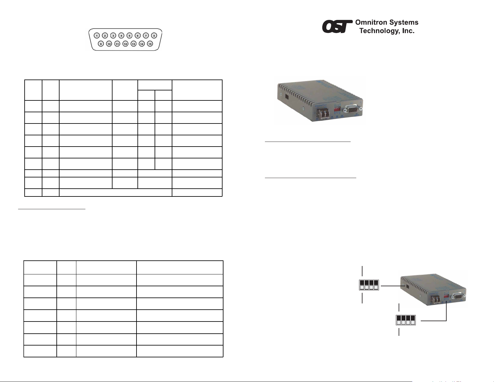
The Omnitron iConverter® X21 is a serial to fiber media converter featuring several
configuration modes enabling connection to a wide variety of X.21 and RS-530
applications. Data rates of up to 8.192Mbps are supported.
The X21 supports standard DCE
sourced timing and terminal timing
modes. The included adapter cable
accommodates different connector
gender types. The X21 features local
loopback on the serial and fiber ports
to facilitate testing and installations.
INSTALLATION PROCEDURE
1) Configure DIP-Switches
2) Install Standalone Module and Connect Cables
3) Verify Operation
1) CONFIGURE DIP-SWITCHES
FRONT PANEL DIP-SWITCH
SW1 - DCE/DTE
When this DIP-switch is in the “DCE” (default) position, the serial port is configured to
connect to a DCE device. When the DIP-switch is in the “DTE” position, the serial port
is configured to connect to a DTE device.
SW2 - SET CLOCK (RXC) POLARITY
When this DIP-switch is in the Receive Clock “RC” (default) position, the clock edge
used to sample the data on the serial port is defined by the TIA/EIA-334-C specification.
When the DIP-switch is in the Receive Clock Inverted “Inv” position, the data on the
serial port is sampled on the
inverted clock edge.
SW3 - DTE SET CLOCK
(TXC) POLARITY
When this DIP-switch is in the
Terminal Timing Clock “TTC”
(default) position, the clock edge
used to sample the data on the
serial port is defined by the TIA/
EIA-334-C specification. When
the DIP-switch is in the Terminal
Timing Clock Inverted “Inv”
position, the data on the serial
port is sampled on the inverted
clock edge.
Figure A: DIP-Switch Location
Page 2
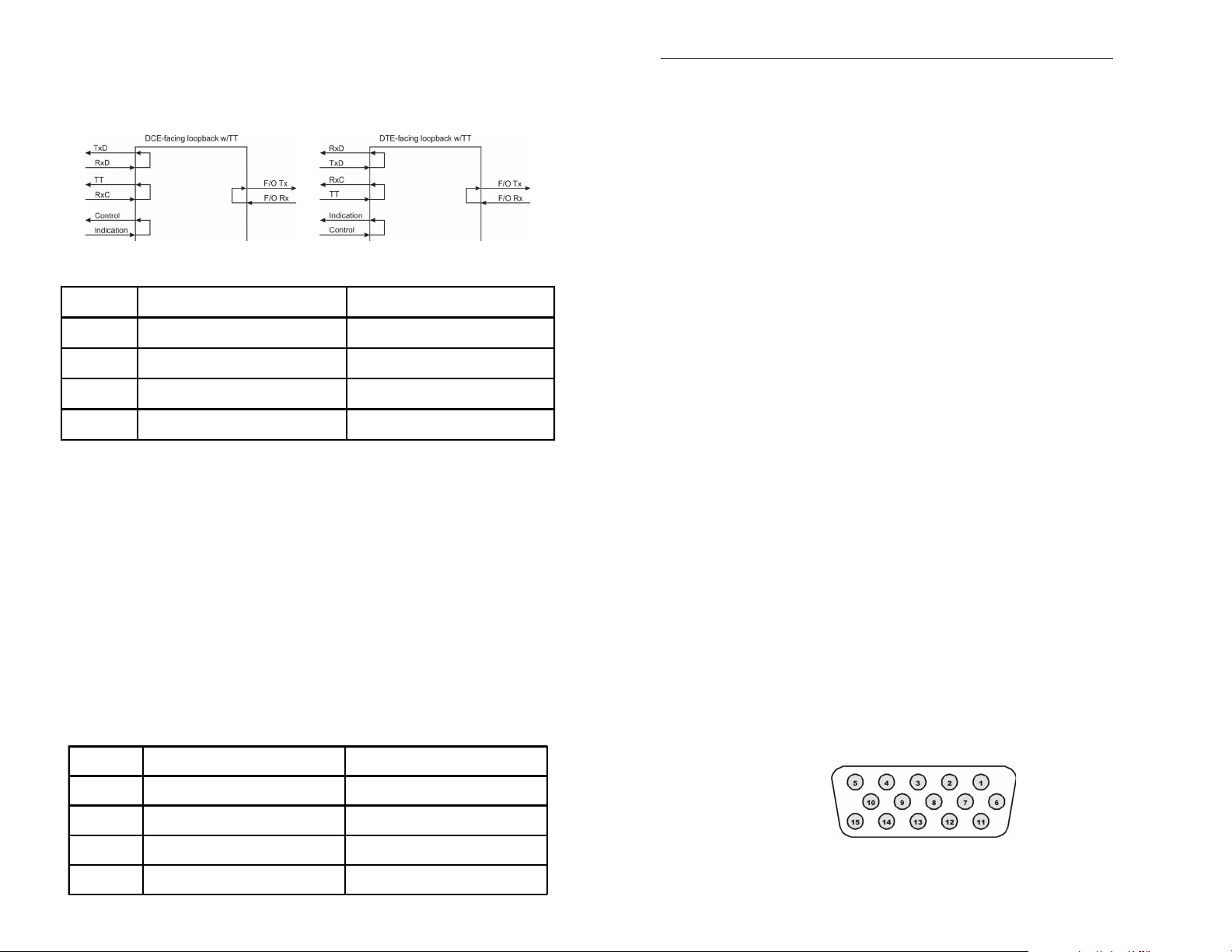
SW4 - LOOPBACK
When “L-LB” is selected, the serial port data signals are looped back to the attached
device. At the same time, the fiber port is looped. If the module has Terminal Timing
enabled (see DIP-SWITCH BANK 1), the clock signals are also looped back to the
attached device.
Figure B: Loopback modes showing Terminal Timing
Switch Down Up
SW1 DCE: DCE Interface enabled DTE: DTE Interface enabled
SW2 RC: RXC Clock polarity normal Inv: RXC Clock polarity inverted
SW3 TTC: TXC Clock polarity normal Inv: TXC Clock polarity inverted
SW4 Norm: Loopback disabled L-LB: Loopback enabled
DIP-SWITCH BANK 1
SW1 -TERMINAL TIMING
When this DIP-switch is in the “Off” (default) position, Terminal Timing is disabled.
When this DIP-switch is in the “On” position, T erminal T iming is enabled. When Terminal
Timing disabled, it uses the ‘Signal Element Timing’ clock (SET clock, circuit S, serial
port pins pair 4, 9) as supplied by the DCE device to time Transmit data (TXD) and
Receive data (RXD). This is called Contra-directional Timing. When Terminal Timing
is enabled, it uses ‘DTE Signal Element Timing’ clock (DTE SET clock, circuit X, serial
port pins pair 10, 14) as supplied by the DTE device to time TXD, and uses ‘Signal
Element Timing’ clock to time RXD. This is called Co-directional Timing.
When Terminal Timing is used, both the local and remote modules must be set to use
Terminal Timing, as well as the devices connected to each module. All four units must
be in Terminal Timing Mode.
SW2, SW3, SW4 -RESERVED
DIP-switches SW2, SW3 and SW4 are for future features. Leave in the default position.
Switch Down Up
2) INST ALL ST ANDALONE MODULE AND CONNECT CABLES
a. The X21 Serial Media Converter is available in tabletop and wall-mounting models.
For wall-mounting, attach the unit to a wall, backboard or other flat surfaces. For
tabletop installations, place the unit on a flat level surface. Attach the rubber feet to
the bottom of the unit to prevent the unit from sliding. Make sure the unit is placed
in a safe, dry and secure location.
To power the unit using the AC/DC adapter, connect the AC/DC adapter to the AC
outlet. Then connect the barrel plug at the end of the wire on the AC/DC adapter to
the 2.5mm DC barrel connector (center-positive) on the chassis. Confirm that the
unit has powered up properly by checking the power status LED located on the
front of the unit.
To power the unit using a DC power source, prepare a power cable using a twoconductor insulated wire (not supplied) with a 14 AWG gauge minimum. Cut the
power cable to the length required. Strip approximately 3/8 of an inch of insulation
from the power cable wires. Connect the power cables to the standalone unit by
fastening the stripped ends to the DC power connector.
Connect the power wires to the DC power source. The Power LED should indicate
the presence of power.
WARNING: Note the wire colors used in making the positive and negative
connections. Use the same color assignment for the connection at the DC
power source.
NOTE: If mounting with a safety ground attachment, use the safety ground
screw at the rear of the unit.
b. When using the SFP model (8859-0), insert the SFP Fiber transceiver into the Port
1 SFP receptacle on the X21 converter (see SFP Data Sheet 091-17000-001 for
supported transceivers).
NOTE: The release latch of the SFP Fiber transceiver must be in the closed
(up) position before insertion.
c. Connect the included adapter cable to the serial port on the X21 converter. Use
the appropriate gender plug to attach the X.21 device.
d. Connect an appropriate multimode or single-mode fiber cable to the fiber port of
the installed module. It is important to ensure that the transmit (TX) is attached to
the receive side of the device at the other end and the receive (RX) is attached to
the transmit side. Single-fiber (SF) media converter models operate in pairs. The
TX wavelength must match the RX wavelength at the other end and the RX
wavelength must match the TX wavelength at the other end.
SERIAL PORT CONNECTOR
The serial port is a three row DE-15 female connector with the following pin-out
configuration.
SW1 Off: Terminal Timing disabled On: Terminal Timing enabled
SW2 Off: Defa ult - Do not c hange
SW3 Off: Defa ult - Do not c hange
SW4 Off: Defa ult - Do not c hange
-
-
-
Figure C: Serial Port DE-15 Connector
 Loading...