

Page 1
iConverter® Gx User Manual
Port 1 (P1)
Port 2 (P2)
iConverter Gx Dual Fiber Modules
Fiber Type Distance
MM 220m/550m - 8502-0 8504-0 8506-0
SM 12 km - 8503-1 8505-1 8507-1
SM 34 km - 8503-2 - 85 07-2
SM 80 km - 8503-3 - 85 07-3
SM 140 km - 8503-5 - -
Fiber /
Connector
SM / SC 20 km 8510-1 8511-1
SM / SC 40 km 8510-2 8511-2
For wide temperature (-40 to 60º C), add a "W" to the end of the
model number. Consult factory for extended temperature(-40 to
+75º C) models.
When using single-fiber (SF) media converter models, the Tx
wavelength on one end has to match the Rx wavelength on the
other.
*A minimum of 3dB of attenuation is required for these models.
For c o mp l e te fibe r s p ecif icat i o ns , r e fe r to thi s p r o d uc t' s d a ta sheet .
iConverter Gx Single-Fib e r Mo d ules
Distance
Type
Connector Type
ST SC MT-RJ LC
Tx: 1310 nm,
Rx: 1550 nm
Tx: 1550 nm,
Rx: 1310 nm
ABOUT THIS MANUAL:
This document supports revision “xx/07” of the iConverter
Gx. Please refer to the serial number label on the Gx for
the revision number of your product. This revision
incorporates the following improvements to the Gx:
1. Enhanced UTP Auto-Negotiation options.
2. Compatibility with NetOutlook and NMM version 3.2
or later.
OVERVIEW:
The iConverter Gx media converter supports the IEEE
802.3 Ethernet Standard and converts 1000BASE-X
fiber to 1000BASE-T unshielded twisted pair (UTP).
Models are available for multimode (MM) and singlemode (SM), dual fiber and single-mode single-fiber.
The Gx supports UTP Half-Duplex and Full-Duplex
auto-negotiation and features UTP automatic crossover
for easy attachment to hubs, switches and workstations.
The Gx can be used in an unmanaged or managed fashion.
When unmanaged, it can be installed in a chassis without
an iConverter Network Management Module (NMM). To
be managed, an NMM or a media converter with integrated
management, such as the GX/TM, must be installed in
the same chassis.
MOUNTING AND CABLE ATTACHMENT:
iConverter modules are hot-swappable and can be installed
into any iConverter chassis.
Installation Instructions
1. Carefully slide the
slot, aligning the module with installation guides. Ensure
that module is firmly seated against backplane.
iConverter module into installation
Page 2 Page 3
2. Secure the module by securing panel fastener screw
(attached to module) to the front of the chassis.
3. Attach the UTP port via a category 5 cable to a
1000BASE-TX Ethernet device.
4. Attach the fiber port via an appropriate fiber cable
(multimode or single-mode) to a 1000BASE-FX Fast
Ethernet device. The iConverter transmit (TX) must
attach to the receive side on other device; the receive
(RX) must attach to the transmit.
5. When using single-fiber (SF) media converter models,
the TX wavelength on one end has to match the RX
wavelength on the other. Based on this guideline, SF
media converter models must be used in pairs, such
as the 8510-1 matched with the 8511-1.
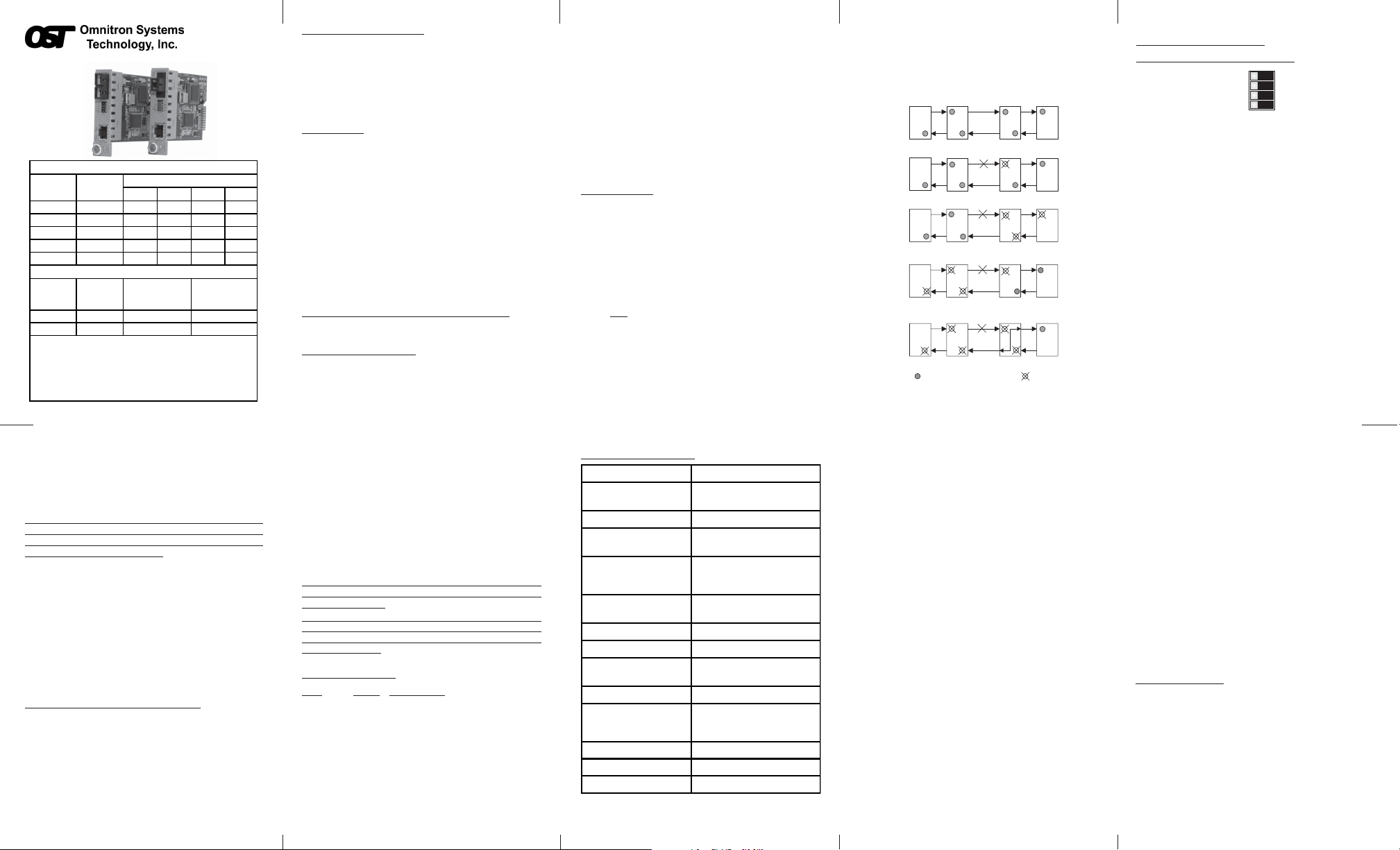
LINK MODES:
In order to accommodate different user needs, the Gx
supports three different linking modes.
In Link Segment (LS), sometimes referred to as Normal
mode, a converter port transmits a Link signal
independently of any received Link at any other port.
For example, the UTP transmits a Link regardless of
the fiber receiving a Link [Fig 1(a) & (b)].
In Link Propagate (LP), sometimes referred to as Link
Loss Carry Forward, a converter port transmits a Link
only when receiving a Link at its other port. For
signal
example, the UTP transmits a Link only when receiving
a Link at the fiber port. [Fig 1(c)].
In Remote Fault Detection + Link Segment (RFD+LS),
the fiber port transmits a Link signal only when receiving
a Link at the fiber port. As a result, fiber faults (no
Link received at the fiber) are looped-back and can be
reported to the network core [Fig. 1(d)].
In Remote Fault Detection + Link Propagate (RFD+LP),
the UTP port transmits a Link signal only when receiving
a Link at the fiber port. The fiber port transmits a Link
signal only when receiving a Link signal at both the fiber
port and the UTP port. As a result, fiber faults are
looped-back and can be reported to the network core
[Fig. 1(e)].
(a)
Switch 1 Converter A Converter B Switch 2
(b)
Switch 1 Converter A Converter B Switch 2
(c)
Switch 1
(d)
Switch 1
(e)
Switch 1 Converter A Converter B Switch 2
UTP
LED Lit
LS
LS
LP
Converter
LP
ConverterAA
LP
Fiber
Fiber
LS
LS
LP
Converter B
RFD+LS
Converter B
RFD+LP
UTP
Switch 2
Switch 2
LED Off
Fig.1 Link Modes
Page 4
DIP-SWITCH SETTINGS:
Front Panel DIP-Switch Settings:
Link Segment
UTP Auto Negotiate
UTP Full-Duplex
Pause Enable
Pause En
=
LS
=
AN
=
FDX
=
UTP
Link Segment/Link Propagate “LS/LP” DIP-Switch:
This DIP-Switch controls Link Segment or Link Propagate
modes. When in the “LS” position, Link Segment mode
is enabled (factory setting). When in the “LP” position,
Link Propagate mode is enabled.
Auto/Manual Negotiate “AN/Man” DIP-Switch:
When the Auto/Manual Negotiate “AN/MAN” DIP-Switch
is in the Auto-Negotiate “AN” position (factory setting)
and the FDX/HDX DIP-Switch is in the “FDX” position,
the converter auto negotiates and matches the duplex
mode of a mating auto-negotiating device connected
to its UTP port. When the “AN/MAN” DIP-Switch is in
the “AN” position and the FDX/HDX DIP-Switch is in
the “HDX” position, the converter auto-negotiates and
operates in half-duplex mode only.
When in the Manual “Man” position, the converter autonegotiates and operates only in the mode selected by
the “FDX/HDX” DIP-Switch.
UTP Full/Half Duplex “FDX/HDX” DIP-Switch:
When the Auto/Manual Negotiate DIP-Switch is in the
Manual “Man” position, the Full/Half-Duplex “FDX/HDX”
DIP-Switch selects the duplex mode for the converter.
When the UTP Full/Half-Duplex DIP-Switch is in the
Page 5
Link Propagate
=
LP
Man
UTP Manual
=
UTP Half-Duplex
HDX
=
Dis
Pause Disable
=
Full-Duplex “FDX” position (factory setting), the
converter operates in Full-Duplex. This is the
recommended mode.
When in the “HDX” position, the converter
auto-negotiates and operates in Half-Duplex.
When the “AN/Man” DIP-Switch is in the “AN”
position, please consult the Auto/Manual
Negotiate DIP-Switch section (pg. 5) for
information on this setting.
It should be noted that Half-Duplex must be used when
connecting to a hub. Full-Duplex can be used when
connecting to a switch, or between a switch and a
Full-Duplex capable workstation.
UTP Pause Enable/Disable “Pause En/Dis” DIP-Switch:
Setting this DIP-Switch to Pause Enable “Pause En”
(factory default) allows the UTP port to auto-negotiate to
Symmetrical and Asymmetrical Pause. Setting the
DIP-Switch to Pause Disable “Dis” forces the UTP port
to auto-negotiate only to No Pause. Pause frames are
always passed through the converter.
Board Mounted DIP-Switch Settings:
Remote Fault Detection DIP-Switch (Not Shown):
The board mounted DIP-Switch controls the Remote
Fault Detection function. To enable Remote Fault
Detection, change the position of DIP 1 from disable
(down, factory default) to enable (up).
When this DIP-Switch is in the enable (up) position and
the “LS/LP” DIP-Switch is in the “LS” position, Remote
Fault Detection + Link Segment mode is enabled. In
Page 6 Page 7 Page 8
RFD+LS mode, the fiber port transmits a Link signal
only when receiving a Link at the fiber port. As a result,
fiber faults (no Link received at the fiber) are looped-back
and can be reported to the network core.
When this DIP-Switch is in the enable (up) position and
the “LS/LP” DIP-Switch is in the “LP” position, Remote
Fault Detection + Link Propagation mode is enabled. In
RFD+LP mode, the Gx propagates the presence or
absence of an incoming Link signal from a Fiber port
receive side to the transmit side of both the Fiber and
the UTP ports.
Note that connecting two converters when both are
set to RFD mode is illegal and will cause a “deadly
embrace” lockup.
The Gx fiber port is always in Manual Mode, and
sometimes a link-up will not occur with other
devices. A user must switch the connected device
to Manual Mode.
LED INDICATORS:
LED Color Description
Pwr: Yellow On--Power on
F/O Lk: Green On--Link; Blink--Activity
FDx: Green On--Full-Duplex mode
UTP/Link: Green On--UTP Link; Blink--Activity
Gx SPECIFICATIONS:
Model Type Gx
Protocols
UTP Connectors
Fiber Connectors
Controls
LED Displays
Dimensions
Weight
Compliance
Pow e r Requirement
Temperature
Humidity
Altitude
MTBF (h r s)
1000BASE-SX/LX,
1000BASE-T
SC, LC, MT-RJ,
Single-Fiber SC
LS/LP, RFD, UTP,
FDX/HDX, AN/Man,
Pause En
Power, FO link,
UTP link, FDX/HDX
W:0.85" x D:4.5" x H:2.8"
UL, CE , FCC Class A ,
NEBS Level 3
1.4A @ 3.3VDC (typical)
Standard: 0 to 50º C
Wide: -40 to 60º C
Storage: -40 to 80º C
5 to 95% (non-condensing)
-100m to 4000m
1,100,000
RJ-45
8 oz.
The operating description in this Instruction Manual is
for use by qualified personnel only. To avoid electrical
shock, do not perform any servicing of this unit other
than that contained in the operating instructions, unless
you are qualified and certified to do so by Omnitron
Systems Technology, Inc.
Warranty
Warning
This product is warranted to the original purchaser
against defects in material and workmanship for a
period of TWO YEARS from the date of shipment. A
LIFETIME warranty may be obtained by the original
purchaser by REGISTERING this product with Omnitron
within 90 days from the date of shipment. TO
REGISTER, COMPLETE AND MAIL OR FAX
ENCLOSED REGISTRATION FORM. Or you may
register your product on the Internet at www.omnitronsystems.com. During the warranty period, Omnitron
will, at its option, repair or replace a product which is
proven to be defective.
For warranty service, the product must be sent to an
Omnitron designated facility, at Buyer’s expense.
Omnitron will pay the shipping charge to return the
product to Buyer’s designated US address using
Omnitron’s standard shipping method.
Limitation of Warranty
The foregoing warranty shall not apply to defects
resulting from improper or inadequate use and/or
maintenance of the equipment by Buyer, Buyersupplied equipment, Buyer-supplied interfacing,
unauthorized modifications or tampering with equipment
(including removal of equipment cover by personnel
Page 9
not specifically authorized and certified by Omnitron),
or misuse, or operating outside the environmental
specification of the product (including but not limited
to voltage, ambient temperature, radiation, unusual
dust, etc.), or improper site preparation or maintenance.
No other warranty is expressed or implied. Omnitron
specifically disclaims the implied warranties of
merchantability and fitness for any particular purpose.
Exclusive Remedies
The remedies provided herein are the Buyer’s sole and
exclusive remedies. Omnitron shall not be liable for
any direct, indirect, special, incidental, or consequential
damages, whether based on contract, tort, or any legal
theory.
Technical Support:
For help with this product, contact our T echnical Support:
Phone: (949) 250-6510
Fax: (949) 250-6514
Address: Omnitron Systems Technology, Inc.
140 Technology Dr., #500
Irvine, CA 92618 USA
E-mail: support@omnitron-systems.com
URL: www.omnitron-systems.com
Form: 040-08500-001K 1/10
Page 10
 Loading...