

Page 1
FlexSwitchTM 2Fx+2U
Model 6540-FK
Replacement Kit
User Manual
140 Technology #500, Irvine, CA 92618
Phone: (949) 250-6510; Fax: (949) 250-6514
Page 2

Table of Contents
1.0 INTRODUCTION.................................................................... 3
1.1 General Description ............................................................. 3
1.2 Chassis Models .................................................................... 3
2.0 INSTALLATION...................................................................... 4
2.1 Chassis Installation .............................................................. 4
2.2 Module Installation............................................................... 4
2.3 Fiber Installation ................................................................... 4
2.4 UTP Installation .................................................................... 4
3.0 CONFIGURATION ................................................................. 5
3.1 AC Site Preparation.............................................................. 5
3.2 AC Powered Chassis Mounting .......................................... 5
3.3 Configuring the DIP-Switches............................................. 6
3.3.1 Media Converter Modules - Front Panel ............................ 6
3.3.2 Media Converter Modules - On-Board................................ 7
4.0 LED INDICA TORS ................................................................. 8
4.1 Media Converter Modules ................................................... 8
5.0 SPECIFICATIONS.................................................................. 9
6.0 LINK MODES....................................................................... 10
Page 2
Page 3

1.0 INTRODUCTION
1.1 General Description
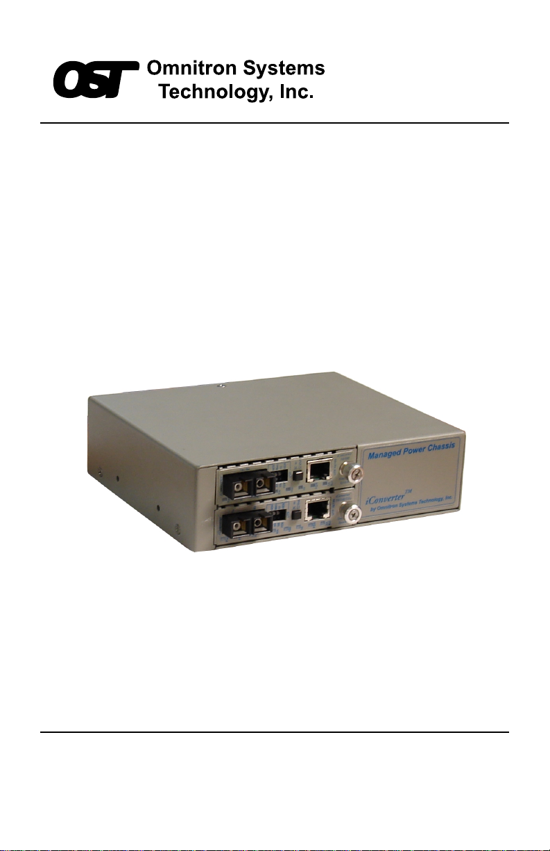
The 6540-FK is the direct replacement for the discontinued FlexSwitch Model
600XC 2Fx + 2U. The 6540-FK replacement kit consists of two iConverter
10/100Base-Tx to 100Base-Fx Media Converter Modules installed in a iConverter
2-Module chassis.
The 6540-FK provides two 10/100 auto-negotiating UTP ports with auto-crossover
and two 100Base-Fx fiber ports.
The two 100Base-Fx fiber ports support half or full duplex operation.
The 6540-FK features front panel accessible DIP-Switches for convenient
configuration of the single UTP and fiber port. On-board DIP-Switches
configure the link mode and backplane operation. The backplane is enabled
by default.
1.2 Chassis Models
FlexSwitch Replacement Matrix
Discontinued Part Replacement Part
6540-0 6540-0-FK
6540-2 6540-2-FK
6540-3 6540-3-FK
6541-0 6541-0-FK
6541-2 6541-2-FK
Replacement Matrix
FlexSwitch Model 6540
Fiber Type Distance
MM 5km 6540-0-FK 6541-0-FK
SM 30km 6540-2-FK 6541-2-FK
SM 60km 6540-3-FK -
Model Numbers
Connector Type
SC ST
Page 3
Page 4
2.0 INST ALLATION
2.1 Chassis Installation
The 6540-FK is designed to accommodate wall-mounting and tabletop
installations. For wall-mounting, the 8249-0 W all-Mount kit (sold separately)
is designed to attach the chassis to a wall, backboard or other flat surfaces.
For tabletop installations, place the unit on a flat level surface. Attach the
rubber feet to the bottom of the chassis to prevent the unit from sliding. Make
sure the unit is placed in a safe, dry and secure location.
For external power installation and configuration, see section 3.0.
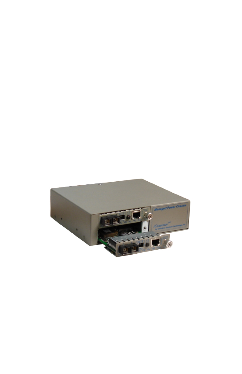
2.2 Module Installation
The modules are pre-installed in the iConverter 2-Module chassis with the
backplane enabled on both modules and Link Segment selected. If the modules
are removed, carefully slide the module into the open slot. Align the module
with the installation guides and ensure that the module is firmly seated against
the backplane. Secure the module by fastening the front panel thumbscrew
(push in and turn clockwise to tighten) to the chassis front.
2.3 Fiber Installation
Connect an appropriate multimode or single-mode fiber cable to the fiber port
of the installed modules. It is important to make sure that the transmit (TX) is
attach to the receive side of the device at the other end and the receive (RX) is
attach to the transmit side.
2.4 UTP Installation
Connect the UTP ports via a Category 5 cable to a 10Base-T or 100Base-Tx
Ethernet device.
Page 4
Page 5
3.0 CONFIGURATION
3.1 AC Site Preparation
• Power source should be available within 5 ft. of the chassis and installed
per the National Electrical Code ANSI/NFPA-70.
• This equipment requires a 100-240VAC, 0.5Amp, 50/60Hz power outlet.
Appropriate overloading protection should be provided on the AC power
source outlets utilized.
• The operating temperature of this equipment is 0 to 50 degrees C. If installed
in a closed or multi-module rack assembly, the operating ambient
temperature of the rack must not exceed the maximum rated 50 degrees C.
• Installation of the equipment should be such that the air flow in the front
and back of the chassis is not compromised or restricted.
• Never use this equipment to carry any weight except its own. Never use it
as a shelf to support the weight of other equipment.
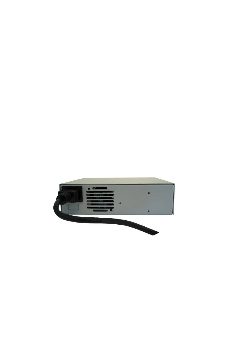
3.2 AC Powered Chassis Mounting
Attach the AC power cord to the back of the Power Receptacle and plug into
the AC outlet. Any installed modules will illuminate the power LED.
Page 5
Page 6

3.3 Configuring the DIP-Switches
The 6540-FK has been pre-configured with Auto-Negotiation enabled on all
UTP ports for plug and play easy of use. However, the iConverter modules
offer additional configuration flexibility.
3.3.1 Media Converter Modules - Front Panel
The Media Converter Modules have been pre-configured as illustrated below .
Using the front panel DIP-Switch, the module can be re-configured for customer
specific applications.
Media Converter Module Front Panel DIP-Switch
Fiber Full/Half-Duplex “FDX / HDX” DIP-Switch
When in the Fiber Full/Half-Duplex DIP-Switch is in the “FDX” position
(factory default), the fiber port operates in Full-Duplex mode. When in the
“HDX” position, the fiber port operates in Half-Duplex mode and its distance
is limited by the IEEE 802.3 standard to 412 meters.
UTP Auto/Manual Negotiate “AN / MAN” DIP-Switch
When the UTP “AN/Man” DIP-Switch is in the Auto-Negotiate “AN” position
(factory default), the converter Auto-Negotiates and matches the 10/100 speed
and duplex mode of a mating Auto-Negotiating device connected to its UTP
port.
When the UTP “AN/Man” DIP-Switch is in the “Man” position, the converter
does not auto-Negotiate and operates in the mode selected by the Full/Half
Duplex “FDX/HDX” and “10/100” DIP-Switches.
UTP 10/100 “10 / 100” DIP-Switch
When the UTP “AN/Man” DIP-Switch is in the “Man” position, the UTP
“10/100” DIP-Switch selects the speed of the UTP port. When in the “100”
position (factory default), the UTP port operates at 100 Mbps. When in the
“10” position the UTP port operates at 10 Mbps.
UTP Full/Half-Duplex “FDX / HDX” DIP-Switch
When the UTP “AN/Man” DIP-Switch is in the “Man” position, the “FDX/HDX”
DIP-Switch selects the duplex mode of the UTP port. When in the “FDX” position
(factory default), the UTP port operates in Full-Duplex mode. When in the
“HDX” position, the UTP port operates in Half-Duplex. Set the duplex mode
to match the connecting device and check for link status.
Page 6
Page 7

Note: Attaching the Auto-Negotiating UTP port of the 6540-FK to a device
with a manual/forced /hard-coded UTP port may result in an unpredictable
port setting with excessive collisions and poor link performance. When
operating in Manual mode, both mating ports MUST be set manually to the
same speed and duplex mode.
3.3.2 Media Converter Modules - On-Board
The Media Converter Modules have on-board DIP-Switches for the
configuration of the Link Modes and Backplane connectivity . See Section 6.0
for more information on the Link Modes. The modules are pre-configured as
illustrated below.
=
4
3
2
1
Media Converter Module On-Board DIP-Switches
Remote Fault Detection “RFD” DIP-Switch
RFD
BPOEN
LP
Down
Remote Fault Detect Enable
=
Backplane Enable
=
Link Propagate/Link Segment
=
Not Used (Factory Set)
When the Remote Fault Detect “RFD” DIP-Switch is in the UP position, the
RFD mode is selected. When in the DOWN position (factory default), the
RFD mode is disabled.
Note: Connecting two converters with both set to RFD mode is an illegal
setting and will cause a “deadly embrace” lockup.
A and B Backplane Enable “BPOEN” DIP-Switch
This DIP-Switch must be in the UP position (factory default) for the module to
operate correctly. The backplane must be enabled for the Media Converter
Modules to communicate.
Link Propagate/Link Segment “LP” DIP-Switch
When both the Link Propagate/Link Segment “LP” and the Remote Fault Detect
“RFD” DIP-Switches are in the DOWN position (factory default), Link Segment
mode is enabled. When the Link Propagate/Link Segment “LP” DIP-Switch is
in the UP position, and the Remote Fault Detect “RFD” DIP-Switch is in the
DOWN position, Link Propagate mode is enabled.
Note: Setting both the “LP” and the “ RFD” to the UP positions on the same
module is an illegal mode that will result in unpredictable behavior.
Page 7
Page 8

4.0 LED INDICA TORS
4.1 Media Converter Modules
The Media Converter Modules have LED indicators to provide information
on how the module is communicating to its link partner. The LED indicators
can also be used to troubleshoot problems with the connections.
Media Converter Module
LED Function Color OFF State ON State
Power " Pwr" Yellow No P ower On: Mod ule ha s power
Fiber "FD X" Green Fiber in Half Duplex On: Fiber in F ull Duplex
Fiber "Lk Act" Green No Fiber Link On: Fiber Li nk is Active
Blinking : Data Acti vity
UTP "AN" Green UTP is in Manual
Negotiation
UTP "100" Green UTP not Linked at
100Mbps
UTP "10" Green UTP not Li nked at
10Mbps
UTP " FDX" Green UTP in Half Duplex On: UTP in Full Duplex
UTP "Lk Act" Green No UTP Link On: UTP Link i s Active
On: UTP has A uto-Negoti ation
Enabled.
On: UTP Linked at 100 Mbps
On: UTP Linked at 10Mbps
Blinking : Data Acti vity
Media Converter Module LED Indicators
Page 8
Page 9

5.0 SPECIFICATIONS
Description Fast Ethernet Switch
with two 10/100 UTP Ports and two 100 Fiber Port
Protocols 10Base-T, 100Base-Tx, 100Base-Fx with 1522
bytes max. frame size
UTP C able Type EIA/TIA 568A/B
Category 5 and higher
Fiber Cable Type Multimode: 50/125, 62.5/125, 100/140um
Singlemode: 9/125um
UTP Connector Type RJ45
Fiber Connector Type Dual Fiber: ST, SC
DIP-Switches Fiber: FDX/HDX
UTP: AN/MAN, 10/100, FDX/HDX
Link Modes: LS, LP, RFD
Power Requirements 100 - 240 VAC @ 0.5A/0.4A, 50/60Hz
Dimensi ons W:6.7" x D:5.51" x H:1.87"
Weight 3.0 lbs
Compliances UL, CE, FCC CLass A, NEBS Level 3
Temperature Operating: 0 to +50 C
Storage: -50 to +80 C
Humidity
(non-condensing)
Altitude (operational) < 4000m (13,000 ft)
< 95%
Page 9
Page 10

6.0 LINK MODES
In order to accommodate different user requirements, the 6540-FK Media
Converter Modules support three different link modes:
Link Segment (LS)
LS mode transmits a link signal independently of any received ‘Link’ at any
port. Utilizing this configuration, a loss of a receive link signal will only affect
the port detecting the loss of signal. All the other ports will continue to generate
a link signal. A loss of link on the UTP port, only affects the UTP port; the
other ports remain unaffected.
Link Propagate (LP)
LP mode transmits a link signal only when a link signal is detected. Utilizing
this configuration, a loss of a receive link signal will continue to “propagate”
through to the next port in the network. A loss of link on the UTP port will
cause the fault to propagated forward causing the fiber and UTP ports at the
remote end to drop its link. This setting allows the loss of a link to be detected
by SNMP or other managed network devices.
Remote Fault Detect + Link Propagate (RFD+LP)
RFD+LP mode transmits a link signal only when a link signal is detected.
When a loss of link is detected, this mode will perform both a loop back and
propagate forward. A loss of RX fiber causes the fault to loop back causing
the port on the other media converter to lose link. It also propagates the fault
forward toward the UTP port causing the UTP port to lose link.
Note: Connecting two converters together both set to RFD+LP mode will
cause a lockup condition. This is an illegal setting.
Page 10
Page 11

Warning
The operating description in this Instruction Manual is for use by qualified
personnel only. To avoid electrical shock, do not perform any servicing of this
unit other than that contained in the operating instructions, unless you are qualified
and certified to do so by Omnitron Systems Technology, Inc.
Caution
All user-required operations can be performed without opening the unit. Never
attempt to open or remove the cover or tamper with the unit. There are no user
replaceable or serviceable parts in this unit. Equipment is not intended to be
installed and used in a place (home, school, or public area) accessible to the general
population.
Warranty
This product is warranted to the original purchaser against defects in material and
workmanship for a period of TWO YEARS from the date of shipment. A
LIFETIME warranty may be obtained by the original purchaser by REGISTERING
this product with Omnitron within 90 days from the date of shipment. TO
REGISTER, COMPLETE AND MAIL OR FAX THE ENCLOSED
REGISTRATION FORM. Or you may register your product on the Internet at
http://www.omnitron-systems.com. During the warranty period, Omnitron will,
at its option, repair or replace a product which is proven to be defective.
For warranty service, the product must be sent to an Omnitron designated facility ,
at Buyer’s expense. Omnitron will pay the shipping charge to return the product
to Buyer’s designated US address using Omnitron’s standard shipping method.
Limitation of Warranty
The foregoing warranty shall not apply to defects resulting from improper or
inadequate use and/or maintenance of the equipment by Buyer, Buyer-supplied
equipment, Buyer-supplied interfacing, unauthorized modifications or tampering
with equipment (including removal of equipment cover by personnel not
specifically authorized and certified by Omnitron), or misuse, or operating outside
the environmental specification of the product (including but not limited to voltage,
ambient temperature, radiation, unusual dust, etc.), or improper site preparation
or maintenance.
No other warranty is expressed or implied. Omnitron specifically disclaims the
implied warranties of merchantability and fitness for any particular purpose.
Exclusive Remedies
The remedies provided herein are the Buyer’s sole and exclusive remedies.
Omnitron shall not be liable for any direct, indirect, special, incidental, or
consequential damages, whether based on contract, tort, or any legal theory.
Page 11
Page 12

TECHNICAL SUPPORT
If you encounter problems with this product, contact Omnitron Technical
Support.
Phone: 800-675-8410
949-250-6510
Fax: 949-250-6514
Address: Omnitron Systems Technology, Inc.
140 Technology Dr., #500
Irvine, CA 92618
Email: support@omnitron-systems.com
URL: http://www.omnitron-systems.com
Page 12
Form: 040-06540-FK1 A 02/07
 Loading...