

Omnitron Systems Technology FlexSwitch 600X, FlexSwitch 600, FlexSwitch 6000, FlexSwitch 6010, FlexSwitch 6100 User Manual
...Page 1

Omnitron Systems Technology, Inc. 1
27 Mauchly #201, Irvine, CA 92618 (949) 250-6510 Fax: (949) 250-6514
Document #040-06000-002
FlexSwitchTM 600X
16/24 Port 10/100 Auto-Sensing
Dual Speed Ethernet Switch
User’s Manual
12 Omnitron Systems Technology, Inc.
Page 2

2 Omnitron Systems Technology, Inc.
SAFETY CONSIDERATIONS
Warning
The operating description in this Instruction Manual is for use by qualified personnel only. To
avoid electrical shock, do not perform any servicing of this unit other than that contained in the
operating instructions, unless you are qualified and certified to do so by Omnitron Systems
Technology, Inc.
Caution
All user-required operations can be performed without opening the unit. Never attempt to open or
remove the cover or tamper with the unit or tamper with the power supply module.
Warranty
This product is warranted to the original purchaser against defects in material and workmanship
for a period of TWO YEARS from the date of shipment. A LIFETIME warranty may be obtained
by the original purchaser by REGISTERING this product with Omnitron within 90 days from the
date of shipment. TO REGISTER, COMPLETE AND MAIL OR FAX THE WARRANTY CARD
enclosed with this manual to the indicated address. Or you may register your product on the
Internet at http://www.omnitron-systems.com. During the warranty period, Omnitron will, at its
option, repair or replace a product which is proven to be defective.
For warranty service, the product must be sent to an Omnitron designated facility, at Buyer’s
expense. Omnitron will pay the shipping charge to return the product to Buyer’s designated US
address using Omnitron’s standard shipping method.
Limitation of Warranty
The foregoing warranty shall not apply to defects resulting from improper or inadequate use and/
or maintenance of the equipment by Buyer, Buyer-supplied equipment, Buyer-supplied interfacing,
unauthorized modifications or tampering with equipment (including removal of equipment cover
by personnel not specifically authorized and certified by Omnitron), misuse, operating outside
the environmental specification of the product (including but not limited to voltage, ambient
temperature, radiation, unusual dust, etc.), or improper site preparation or maintenance.
No other warranty is expressed or implied. Omnitron specifically disclaims the implied warranties
of merchantability and fitness for any particular purpose.
Exclusive Remedies
The remedies provided herein are the Buyer’s sole and exclusive remedies. Omnitron shall not
be liable for any direct, indirect, special, incidental, or consequential damages, whether based on
contract, tort, or any legal theory.
FCC Warning
This equipment has been tested and found to comply with the limits for a class A digital device,
pursuant to part 15 of the FCC rules. These limits are designed to provide a reasonable protection
against harmful interference when the equipment is operated in a commercial environment. The
equipment generates, uses, and can radiate radio frequency energy and, if not installed and
used in accordance with the instruction manual, may cause harmful interference to radio
communications. Operating this equipment in a residential area is likely to cause harmful
interference in which case the user will be required to correct the interference at his own expense.
Any changes or modifications not expressly approved by the manufacturer could void the user
authority to operate the equipment.
Form:040-06000-002 3/02
Omnitron Systems Technology, Inc. 11
Omnitron Systems Technology, Inc. 11
TECHNICAL SUPPORT
For assitance in installing this product, contact Omnitron’s Technical Support
Department.
Phone: (949) 250-6510
Fax: (949) 250-6514
Address: Omnitron Systems Technology, Inc.
27 Mauchly #201
Irvine, CA 92618, USA
Email: support@omnitron-systems.com
URL: www.omnitron-systems.com
NOTES
Page 3
Omnitron Systems Technology, Inc. 3
FlexSwitch
TM
600X
10/100 Auto-Sensing Ethernet Switch
User’s Manual
GENERAL DESCRIPTION
The FlexSwitch 600X is a family of 16/24 port dual speed 10/100 workgroup Ethernet
switches. They feature an optional interface module that can be used to connect to
other switches, hubs or workstations via multimode or single-mode fiber or provide
additional 10/100 UTP copper ports. This User’s Manual describes the following models:
Model Description
6000 FlexSwitch 600X, 24@10/100 RJ45 Ports, No Plug-In Option
6010 FlexSwitch 600X, 16@10/100 RJ45 Ports, No Plug-In Option
6100 FlexSwitch 600X, 24@10/100 RJ45 Ports, With Plug-In Option
6110 FlexSwitch 600X, 16@10/100 RJ45 Ports, With Plug-In Option
The FlexSwitch 600X family supports the plug-in modules listed below. It should be
noted that the modules are available with a variety of multimode or single-mode fiber
types and that the appropriate models must be used to assure the best performance
and reliability.
Model Description
6300 8@10/100 RJ45 Ports
6310/11 1@100 SC/ST Fiber Port
6320/21 2@100 SC/ST Fiber Ports
6330/31 4@100 SC/ST Fiber Ports
Each RJ45 port auto-senses the maximum performance of an Ethernet device
connected to it via an unshielded twisted pair (UTP) wiring. It automatically selects
and provides 10Base-T or 100Base-Tx speed and full-duplex or half-duplex connection.
The fiber interface modules are fixed in their functionality and provide 100Base-Fx
multimode or single-mode SC or ST connectivity options. Their full-duplex or halfduplex operation is selected by an individual per-port toggle-switch.
The FlexSwitch monitors and reports port activity. It detects the connected operational
devices and displays their connection via a pair of LEDs for each port. The top LED is
a Yellow / Green LED that monitors the speed and activity of the port. When lit “solid,”
it indicates that a Link signal has been detected; and when flashing, it indicates that
port activity is present. The color indicates the speed of the connected device: yellow
means 10Base-T (standard Ethernet) and green means 100Base-Tx (Fast Ethernet).
When lit “solid,” the bottom LED (green) indicates a full-duplex operation, when dark it
indicates half-duplex.
10 Omnitron Systems Technology, Inc.
SPECIFICATIONS
n Protocol: IEEE 802.3
Ethernet 10Base-T
Fast Ethernet 100Base-Tx, 100Base-Fx (plug-in modules)
Flow Control 802.3x
n Basic Features:
MAC Addresses 4,096
Buffer Size 4 MB
n Connectors and Cables:
Twisted Pair UTP: RJ45, Category 5 (EIA/TIA 568)
Fiber: SC or ST
Multimode (MM): 50/125, 62.5/125, 100/140 µm
Single-Mode (SM): 9/125 µm
n Supported Distances:
Fast Ethernet Half-Duplex Full-Duplex
Twisted Pair UTP: 100 m / 328 ft. 100 m / 328 ft.
Multimode, Lx (MM): 412 m / 1,350 ft. 2 km / 1.2 mi.
Single-mode, Lx (SM): 412 m / 1,350 ft. 28 km / 16.8 mi.
Single-mode, LH, Lx (SM): 412 m / 1,350 ft. 58 km / 36 mi.
Note: Distances shown are per fiber port.
n Dimensions / Weight: W:19.0"xD:8.0"xH:1.75" / 7 lb.
n Power: 110 / 230 VAC, 50 / 60 Hz, 300 mA
n Temperature:
Operating 0 to 40 degrees C
Storage -40 to 75 degrees C
n Humidity: 0-90% (non-condensing)
ds60005
(C)
(B)
FlexSwitch 600X
24@10/100
100 Mbps Hub
100 Mbps Switch
(D)
Media
Converter
Media Converters
Media
Converter
(A)
(E)
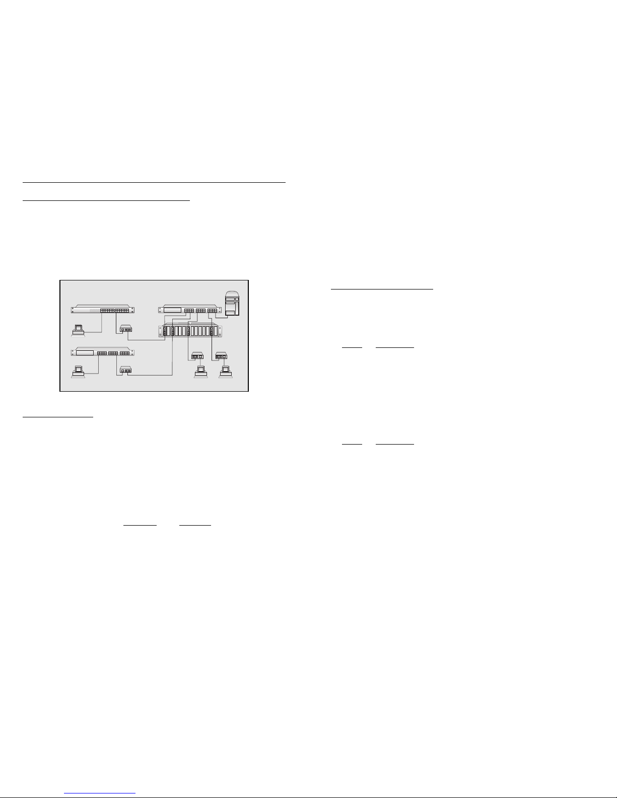
Application 2. Switched Low-Cost Fiber Backbone
This application depicts a fiber backbone utilizing a 10/100 UTP switch (A) and several
chassis-based (B) and stand-alone media converters. In this case the UTP lines are
converted into fiber and connected to Fast Ethernet stations (C), a Fast Ethernet hub
(D) and a Fast Ethernet switch (E). Because of the nature of hubs, the fiber distance is
up to 100-200 m (330-660 ft.) depending on the specifications of the hub. The fiber
connected switch (D) and stations (C) is capable of reaching distances of up to 58 km
(36 mi.).
Page 4
4 Omnitron Systems Technology, Inc.
The FlexSwitch provides a special uplink feature on the Port 1 RJ45 connector. This
uplink connector is equipped with a crossover switch that can switch between the
receiving and transmitting wire pairs. This eliminates the need for a “crossed cable”
which is otherwise required for a connection to another switch or to a hub.
The fiber and UTP uplink modules provide displays to show data speed, link and activity,
half/full duplex status and collisions. Controls include half-duplex and full-duplex
switches for fiber ports on modules with fiber. The module with UTP ports (model
#6300) also features the crossover switch function on one port.
CONTROLS AND INDICATORS
FlexSwitch 600X Chassis:
(Models 6000, 6010, 6100, 6110)
Port 1 Control Switch
This switch provides the crossover feature for port 1 of the switch. It should be set to
the “straight” position for connection to a station or “crossover” position for connection
to a hub or a switch.
Position Description
Out Straight, use when connecting port 1 to a PC or workstation.
In Crossover, use when connecting port 1 to a switch or hub.
Common LEDs Display
Function Color/State Description
Power Yellow / ON Power applied
Per-Port LEDs Display
Function Color/State Description
Link / Speed Green / ON 100Base-Tx (Fast Ethernet) device detected
Green / Flash Data activity present
Yellow / ON 10Base-T (standard Ethernet) device detected
Yellow / Flash Data activity present
OFF No connection
DPX Green / ON Full-Duplex
OFF Half-Duplex
Flash Collisions
FlexSwitch 600X 10/100Tx UTP Plug-In Module:
(Model 6300)
The 10/100Tx module provides 8 additional UTP ports for the FlexSwitch 600X chassis.
Featuring the same 10/100 auto-sensing technology as the main chassis, this plug-in
serves to increase the port density to 32 ports.
Omnitron Systems Technology, Inc. 9
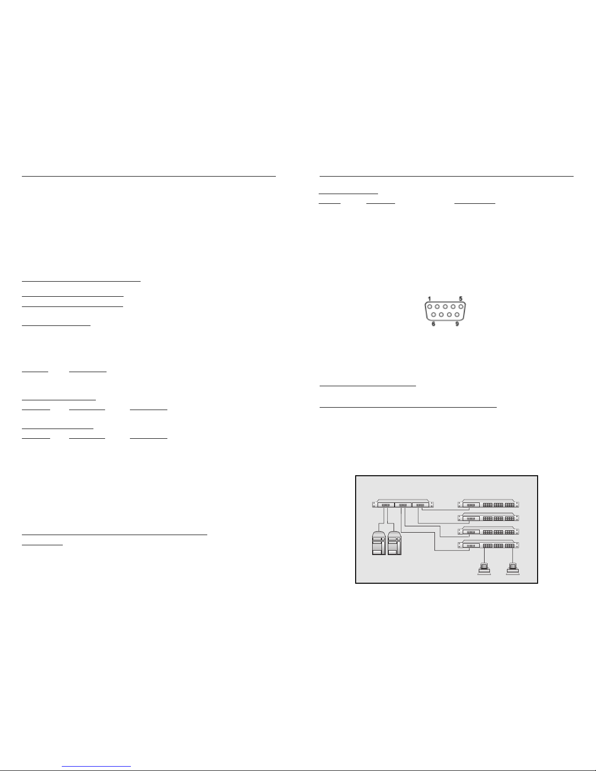
SAMPLE APPLICATIONS
Application 1. 10/100 Workgroups with Fiber Backbone
This application depicts a typical 10/100 UTP switched workgroup network where a
variety of Fast Ethernet and legacy Ethernet workstations are connected to file servers
via fiber. In this example, 24-port FlexSwitch 600X switches (B) are used to connect
the workgroup stations (D). The workgroup switches are connected via fiber to the 6port FlexSwitch 600X3 fiber backbone switch (A). The file servers (C) are also connected
to the backbone server providing fair access to the servers from all workstations.
FlexSwitch 600X3
6-Port 100Base-Fx Switch
FlexSwitch 600X
2@100Base-Fx+24@10/100
10/100
UTP
100Base-Fx
Fiber Uplinks
File
Servers
ds60006
(A) (B)
(C)
(D)
DB-9 Cable Pinout
DB-9M Function Abbreviation
Pin #1 Data Carrier Detect CD
Pin #2 Receive Data RD or RX or RXD
Pin #3 Transmitted Data TD or TX or TXD
Pin #4 Data Terminal Ready DTR
Pin #5 Signal Ground GND
Pin #6 Data Set Ready DSR
Pin #7 Request To Send RTS
Pin #8 Clear To Send CTS
RS232 DB-9 Connector
Page 5

Omnitron Systems Technology, Inc. 5
Crossover Control Switch
This switch provides the crossover feature for port 1 of the module. It should be set to the
“straight” position for connection to a station or “crossover” position for connection to a
hub or a switch.
Position Description
Out Straight, use when connecting port to a PC or workstation.
I n Crossover, use when connecting port 1 to a switch or hub.
Common LEDs Display
Function Color/State Description
Power Yellow / ON Power applied
Per-Port LEDs Display
Function Color/State Description
Link / Speed Green / ON 100Base-Tx (Fast Ethernet) device detected
Green / Flash Data activity present
Y ellow / ON 10Base-T (standard Ethernet) device detected
Y ellow / Flash Data activity present
OFF No connection
DPX Green / ON Full-Duplex
OFF Half-Duplex
Flash Collisions
FlexSwitch 600X 100Fx Fiber Plug-In Modules:
(Models 6310, 6311, 6320, 6321, 6330, 6331)
Since the IEEE 802.3 standard defines the Ethernet 10Base-FL fiber differently than
the Fast Ethernet 100Base-Fx, it should be noted that they are incompatible. The 100Fx
modules support 100Base-Fx only. They operate in half- or full-duplex modes of operation.
Mode Control Switch
This switch controls the half/full-duplex operation of the fiber port. Half-duplex should be
used when connecting to a hub (with a shared/non-switched fiber port) or a workstation
that supports only half-duplex. Full-duplex can be used when connecting to a switch or a
workstation that supports full-duplex operation.
Function Position Description
FDX/HDX Up Select Full-Duplex
Down Select Half-Duplex
Per-Port LEDs Display
Function Color/State Description
Link Green / ON 100Base-Fx (Fast Ethernet) device detected
Green / Flash Data activity present
OFF No connection
DPX Green / ON Full-Duplex
OFF Half-Duplex
8 Omnitron Systems Technology, Inc.
Port Configuration via the Port Management Serial Interface (All Ports)
The FlexSwitch 600X has the ability to force ports to a particular speed (10 or 100
Mbps) or duplex (half/full-duplex) through the use of a serial interface. The serial interface
is located on the rear of the FlexSwitch 600X and has the ability to configure all ports
on the chassis via ASCII terminal or terminal emulator. This feature allows connections
with devices that do not auto-negotiate properly. Use the following steps to configure
these ports with the serial interface.
1. Attach a DB-9 serial cable to the FlexSwitch 600X and attach the other end to a
ASCII terminal or terminal emulator.
2. Press the enter key after the connection has been established and the main menu
will appear on the screen with several options.
3. To view the configuration of all ports on the switch select the “Display port mode
configuration” option.
4. Follow the on screen instructions to make the desired changes to the FlexSwitch
600X port configurations.
5. To exit the main menu simply turn off the ASCII terminal/terminal emulator or
disconnect the serial cable from the rear of the unit.
NOTES:
a. All changes made through the serial interface will affect the unit immediately and
will remain in effect until changed again through the serial interface or via manual
switches.
b. If the power is turned off at the switch the current port settings will be restored when
the power is turned back on.
c. Any changes made through the serial interface for ports 1 through 4 will override
the switch settings for that port until the port is configured manually again.
NOTE: The following values need to be used to communicate properly with the serial
interface.
Baud 4800
Data Bits 8
Parity None
Stop Bits 1
Flow Control None
Page 6
6 Omnitron Systems Technology, Inc.
SITE PREPARA TION
The following is the minimal physical location preparations needed:
1. Power - A power outlet should be available within 5 feet of the unit.
2. Cabling - The following cabling should be used:
a. 10Base-T / UTP - Ideally the site should be cabled with category 5 wiring to maximize
performance but a category 3 or better is acceptable (100 ohms, 24 AWG solid
copper).
b. 100Base-Tx / UTP - The site should be cabled with category 5 wiring to maximize
performance (100 ohms, 24 AWG solid copper).
c. 100Base-Fx / Fiber - Use 50/125, 62.5/125 or 100/140 micron multimode fiber
or 9/125 micron single-mode fiber.
UNPACKING
1. Visual Inspection - Before unpacking, a visual inspection should be conducted in
order to detect any physical damage to the equipment. Any evidence of damage
should be noted and reported immediately.
2. Unpacking - Place shipping container on a flat surface, cut straps or tape, open
top. T ake out each item carefully and place securely on a clean flat surface. Return
all packing material into container (foam, boxes etc.), close and store away for
future reuse.
3. Inspection - Inspect each item for any apparent physical damage. Any evidence of
damage should be noted and reported immediately.
INVENTORY
Review content; the following items should be included:
(1) FlexSwitch 600X unit (Including any pre-configured Plug-In module).
(1) Power cord.
(1) User’s Manual (this document).
Please note any missing items or discrepancies and report them immediately.
INSTALLATION
Cabling and Power-Up
1. Plug the power cord into the FlexSwitch 600X and the other side to the appropriate
AC outlet.
2. Plug any Ethernet 10Base-T or 100Base-Tx workstations into the RJ45 connectors.
The corresponding Link LED should turn ON.
3. Connect port 1 to a workstation or another switch or hub. When connecting to a
workstation set the crossover switch to the “Out” (Straight) position (factory setting).
When connecting to another hub set the switch to the “In” (Crossed) position. When
the device at the far end has become active, the port 1 Link LED should become
ON.
Omnitron Systems Technology, Inc. 7
4. Plug any additional Ethernet 10Base-T or 100Base-Tx switches or hubs into any
of the remaining RJ45 connectors. The corresponding Link LED should turn ON.
Note that a switch or a hub require a crossover cable (not provided) except when
plugged into port 1 of the FlexSwitch 600X as described in “step c” above.
5. Connect any fiber uplink cables to a fiber workstation, converter, switch or fiber
hub. Connect the Transmit (Tx) fiber of the FlexSwitch to a Receive (Rx) fiber on
the connected device. Connect the Receive (Rx) fiber of the FlexSwitch to a transmit
(Tx) fiber on the connected device.
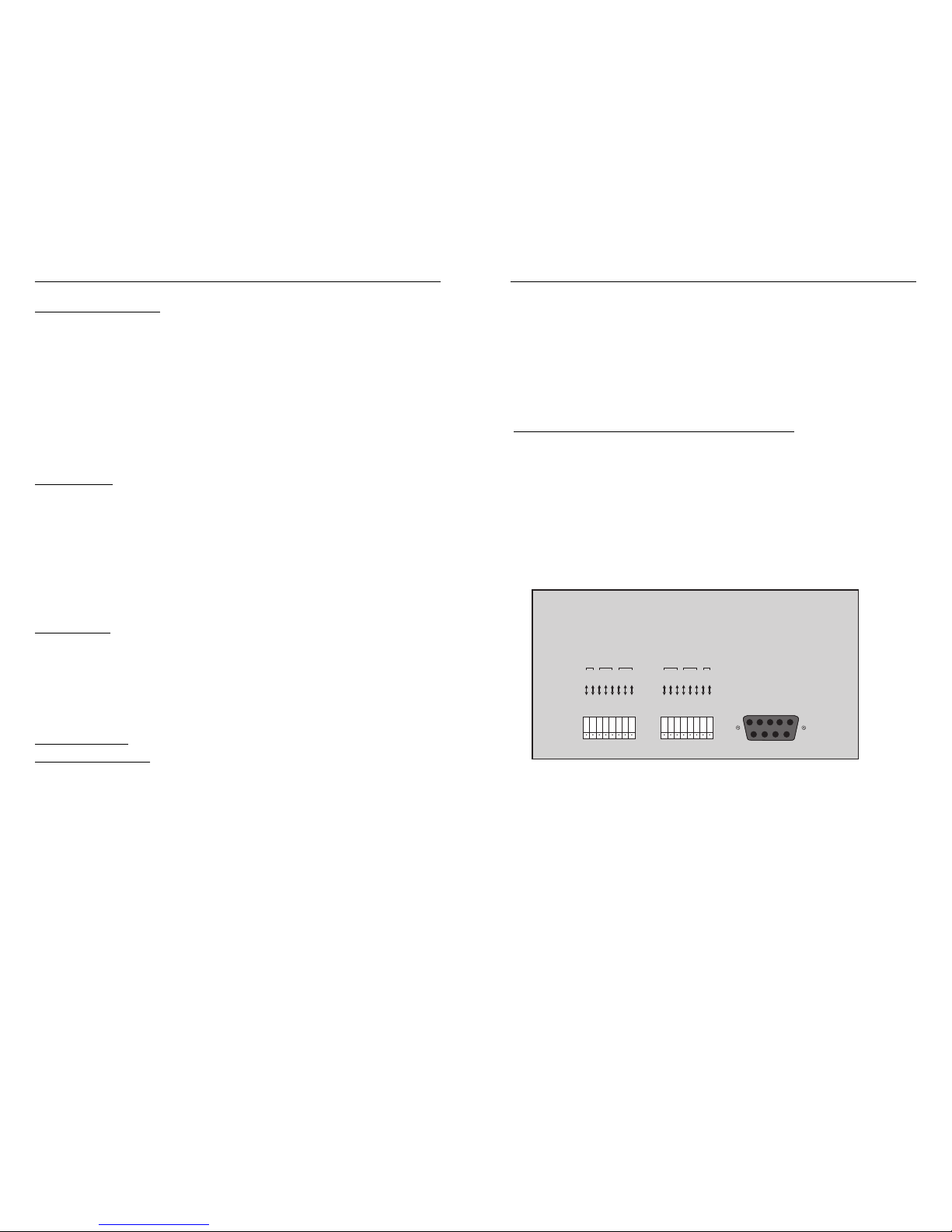
Manual Port Configuration with Switches (Ports 1 to 4)
The FlexSwitch 600X has the ability to force ports to a particular speed (10 or 100
Mbps) or duplex (half/full-duplex) through the use of switches. These switches are
located on the rear of the FlexSwitch 600X and control ports 1 through 4 of the main
chassis. Setting the switches to “Auto” enables the port to determine the speed and
duplex mode automatically. If the connected device cannot provide the proper signal
to indicate its own mode of operation, the manual switches should be used. This
feature allows connections with devices that do not auto-negotiate properly. Use the
following steps to manually configure these ports.
1. Turn off auto-negotiation (Auto) to the desired port by flipping the appropriate switch
to the manual position (Man).
2. Adjust the 10/100 Mbps switch to the speed of the connecting device and check
for link status.
3. Adjust the half/full-duplex switch to accommodate the connecting device and check
for link status.
Manual Switches
Port 1-4 Configuration
HDX
10
Auto
HDX
10
Auto
FDX
100
Man
FDX
100
Man
Tst1
21
HDX
10
Auto
HDX
10
Auto
FDX
100
Man
FDX
100
Man
Tst2
43
Port Management
 Loading...