

Page 1

12 Omnitron Systems Technology , Inc.
SPECIFICATIONS
Protocol: IEEE 802.3, 10Base-T, 100Base-Tx, 100Base-Fx
Interface Connectors:
UTP: (12/24) RJ45 pins 1-2, 3-6 active
Fiber Optic: (1) SC or ST
Cable T ypes:
UTP , 10Base-T: EIA/TIA 568, Category 3, 4, or 5
UTP , 100Base-Tx: EIA/TIA 568, Category 5
Fiber , Multimode (MM): 50/125, 62.5/125, 100/140 um
Fiber , Single-Mode (SM): 9/125 um
Supported Distances:
UTP: 100 m / 328 ft.
MM, Extended: 2 km / 1.2 mi.
SM, Extended: 25 km / 15 mi.
SM, Long Haul (LH): 58 km / 35 mi.
Indicators:
Hub:
Power: LED (1), Yellow (10/100) or Green (100), power applied
Activity 10: LED(1), Green, activity detected
Collision 10: LED (1), Y ellow , collision detected
Activity 100: LED(1), Green, activity detected
Collision 100: LED (1), Y ellow , collision detected
Link / Partition: LED (12/24), Green, per port: device detected / port partitioned
Port Speed: LED (12/24), Green, per port: 10 / 100 / Searching
100Fx and 10/100Tx Modules:
Data Received: LED (1), Green, data received
Link / Speed: LED (1), Green / Y ellow , device detected and 10/100 speed
Duplex Mode: LED (1), Green / Y ellow, Full-Duplex / Half-Duplex
Collision: LED (1), Y ellow, collision detected
Switches:
Hub:
UTP Crossover: Straight / Crossed
Stack Control: Base / Stack
Port Access Control: 6/12 Switches, 2 per 4 ports: Auto-Sensing / 100Base-Tx / 10Base-T
100Fx Module:
Duplex Mode: Full / Half-Duplex
10/100Tx Module:
UTP Crossover: Straight / Crossed
Auto-Sensing Mode: Auto-Sensing / Manual
Duplex Mode: Full-Duplex / Half-Duplex
Speed Control: 100Base-Tx / 10Base-T
Dimensions / W eight: W:19.0"xD:8.0"xH:1.75" / 7 lb.
Power: 110 / 230 VAC, 50 / 60 Hz
Temperature: 0 to 40 degrees C
Humidity: 0-90% (non-condensing)
Omnitron Systems Technology, Inc. 1
FlexCenter™ 200
Auto-Sensing
Dual Speed 10/100 and 100 Stackable
Ethernet Hubs
User Manual
TECHNICAL SUPPORT
For assitance in installing this product, contact Omnitron’s Technical Support Department:
Phone: (949) 250-6510, Fax: (949) 250-6514
Address: Omnitron Systems Technology, Inc.
27 Mauchly, #201
Irvine, CA 92618, USA
Email: support@omnitron-systems.com
URL: www.omnitron-systems.com
27 Mauchly #201, Irvine, CA 92618 (949) 250-6510 Fax: (949) 250-6514
Page 2
2 Omnitron Systems Technology , Inc.
Omnitron Systems Technology, Inc. 11
Safety Considerations
Warning
The operating description in this Instruction Manual is for use by qualified personnel only. T o avoid
electrical shock, do not perform any servicing of this unit other than that contained in the operating
instructions, unless you are qualified and certified to do so by Omnitron Systems T echnology , Inc.
Caution
All user-required operations can be performed without opening the unit. Never attempt to open
or remove the cover or tamper with the unit or tamper with the power supply module.
Warranty
This product is warranted to the original purchaser against defects in material and workmanship
for a period of TWO YEARS from the date of shipment. A LIFETIME warranty may be obtained by
the original purchaser by REGISTERING this product with Omnitron within 90 days from the date
of shipment. TO REGISTER, COMPLETE AND MAIL OR FAX THE REGISTRATION CARD INCLUDED
IN THIS INSTRUCTION MANUAL TO THE INDICATED ADDRESS. During the warranty period,
Omnitron will, at its option, repair or replace a product which is proven to be defective.
For warranty service, the product must be sent to an Omnitron designated facility, at Buyer’s
expense. Omnitron will pay the shipping charge to return the product to Buyer’s designated US
address using Omnitron’s standard shipping method.
Limitation of Warranty
The foregoing warranty shall not apply to defects resulting from improper or inadequate use and/or
maintenance of the equipment by Buyer, Buyer-supplied equipment, Buyer-supplied interfacing, unauthorized modifications or tampering with equipment (including removal of equipment cover by personnel not specifically authorized and certified by Omnitron), misuse, operating outside the environmental specification of the product (including but not limited to voltage, ambient temperature, radiation, unusual dust, etc.), or improper site preparation or maintenance.
No other warranty is expressed or implied. Omnitron specifically disclaims the implied warranties of
merchantability and fitness for any particular purpose.
Exclusive Remedies
The remedies provided herein are the Buyer’s sole and exclusive remedies. Omnitron shall not be
liable for any direct, indirect, special, incidental, or consequential damages, whether based on contract, tort, or any legal theory.
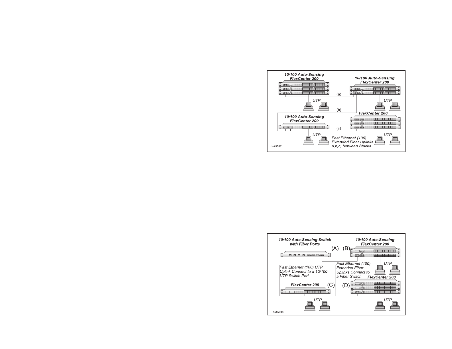
Application 7. Flat Fiber Backbone
This application depicts a flat fiber backbone where hubs are stacked, and connected via extended
fiber uplinks. As shown in this example, the module slots are used both for stacking as
well as for fiber modules. Using the extended distance modules isolates the collision
domains between each stack and facilitates a network that can span up to 58 km (35 mi.)
per uplink.
Application 8. Collapsed / Switched Fiber Backbone
This application depicts a collapsed fiber backbone where hubs are stacked, and
connected via fiber and UTP uplinks to a single location, 10/100 auto-sensing switch with
fiber ports, in a star fashion. This application is similar to the flat backbone with the
difference of being a single point of management and control for the different subnetworks.
In this case two stacks of hubs, B and D, are connected via extended distance fiber
modules to the fiber ports of the switch. The hub in location C is connected via UTP to a
10/100 UTP port on the switch and is able to reach a distance of 100 m (328 ft.).
FCC Warning
This equipment has been tested and found to comply with the limits for a class A digital device,
pursuant to part 15 of the FCC rules. These limits are designed to provide a reasonable protection
against harmful interference when the equipment is operated in a commercial environment. The
equipment generates, uses, and can radiate radio frequency energy and, if not installed and used in
accordance with the instruction manual, may cause harmful interference to radio communications.
Operating this equipment in a residential area is likely to cause harmful interference in which case the
user will be required to correct the interference at his own expense. Any changes or modifications not
expressly approved by the manufacturer could void the user authority to operate the equipment.
Form:040-04500-003 9/03
Page 3

10 Omnitron Systems Technology , Inc.
Application 5. Single Wiring Closet / Multiple Hubs
This application depicts a single-wiring-closet-based network. It is a typical stacking
application of the FlexCenter 200. In this case six hubs are stacked, accommodating up
to 150 stations (144 ports plus six modules).
Application 6. Multiple Wiring Closets / Multiple Hubs
This case depicts two stacks of hubs connected via a fiber uplink. Since an extendeddistance-bridge-based module is used, full-duplex operation is possible for distances of 2
km (1.2 mi.) using multimode fiber, and 58 km (35 mi.) using single-mode fiber .
Omnitron Systems Technology, Inc. 3
FlexCenter 200
Auto-Sensing Dual Speed 10/100 and 100
Stackable Ethernet Hubs
User Manual
GENERAL DESCRIPTION
The FlexCenter 200 is a family of 12/24 port dual speed 10/100 and 100 stackable
workgroup Ethernet hub repeaters. They feature two optional interface modules used
for stacking and uplink interfaces to multimode and single-mode fiber hubs, switches
or workstations. This User’s Manual describes the following base models:
Model Description
4500 FlexCenter 200, 10/100, 12 Ports
4501 FlexCenter 200, 10/100, 24 Ports
4550 FlexCenter 200, 100, 12 Ports
4551 FlexCenter 200, 100, 24 Ports
The following modules are supported by the FlexCenter 200:
4570 10/100Tx, UTP , XD
4571 100Fx, Fiber, XD, SC/MM, 2 km / 1.2 mi.
4572 100Fx, Fiber, XD, SC/SM, 25 km / 15 mi.
4573 100Fx, Fiber, XD, ST/MM, 2 km / 1.2 mi.
4574 100Fx, Fiber, XD, ST/SM, 25 km / 15 mi.
4575 100Fx, Fiber, LH/XD, SC/SM, 58 km / 35 mi.
4576 100Fx, Fiber, LH/XD, ST/SM, 58 km / 35 mi.
4580 100Tx, UTP, SD, 100 m / 328 ft.
4581 100Fx, Fiber, SC/MM, SD, 100-200 m / 328-656 ft.
4582 100Fx, Fiber, SC/SM, SD, 100-200 m / 328-656 ft.
4583 100Fx, Fiber, ST/MM, SD, 100-200 m / 328-656 ft.
4584 100Fx, Fiber, ST/SM, SD, 100-200 m / 328-656 ft.
4590 STK, Stack Module
The FlexCenter’s 12/24 RJ45 ports provide 10Base-T or 100Base-Tx unshielded
twisted pair (UTP) wiring. Its fiber interface modules provide 100Base-Fx multimode
or single-mode SC or ST connectivity options for a variety of applications. The stacking module provides cable connection between stacked hubs.
The FlexCenter monitors and reports port activity. It detects operational devices
connected and displays their connection via a per-port green Link / Partition (L/P)
LED. If a port violates transmission rules, it is disconnected automatically (partitioned) and the L/P LED starts flashing indicating the “Partition” error status. The port
is reconnected only after normal behavior is restored. The per-port speed is indicated by a second per-port LED that flashes while not connected to a device, turns on
“solid” when detecting a 100 station and turns “off” when detecting a 10 station.
Page 4

4 Omnitron Systems Technology , Inc.
Omnitron Systems Technology, Inc. 9
The hub detects and displays per-segment activity (green LED) and collisions (yellow LED) for Ethernet and Fast Ethernet segments.
The FlexCenter features a special uplink Port 1 RJ45 connector. This uplink connector is equipped with a crossover switch that can switch between the receiving and
transmitting wire pairs. This feature eliminates the need for a “crossed cable” which
is otherwise required for connection between hubs.
The fiber and UTP uplink modules provide displays to show data speed, link and
activity, half/full duplex status and collisions. Controls include half/full duplex, autosensing and speed. The UTP module also features a crossover switch.
CONTROLS AND INDICATORS
FlexCenter 200 Mainframe:
Port 1 Control Switch
This switch provides the crossover feature for port 1 of the hub. It should be set to the
straight position for connection to a station or crossover position for connection to a
hub or a switch.
Position Description
Out Straight, use when connecting port 1 to a PC or workstation.
In Crossed-Over, use when connecting port 1 to another hub or switch.
Stack Control Switch
This switch controls the stacking features of the FlexCenter 200. When the FlexCenter 200 is used stand-alone, it must be set to the “Base’ position. When in a
stack, the first hub in a stack (with the “Out” cable only in the STK module) must be set
to the “Base”, and all other hubs must be set to the “Stack” position.
Application 2. 10Base-T and 100Base-Tx Integration via Fiber
In this case an Ethernet 10Base-T hub is connected to the FlexCenter 200 via a fiber
uplink. Since the Ethernet 10Base-FL fiber is specified (by 802.3) as 850 nm and the
Fast Ethernet 100Base-Fx fiber is specified as 1300 nm, they can never be connected.
The 10Base-FL link must be converted to 10Base-T before being connected to the
FlexCenter 200’s 10/100 UTP port. The 100Base-Fx uplink from the Fast Ethernet hub is
connected to the FlexCenter 200’s extended fiber uplink module facilitating 100 to 200 m
of fiber (depending on the Fast Ethernet hub’s network layout).
Application 3. 10Base-2 Coax to 100Base-Tx Integration
This application depicts the integration of legacy coax 10Base-2 network segments to a
modern 10/100 FlexCenter 200 hub. The first case (top) depicts connection via a 10Base2 Coax to 10Base-T UTP converter to a 10/100 FlexCenter 200 port. In the second case
(bottom), the distance between the coax segment and the FlexCenter 200 is more than
100 meters and it requires fiber conversion. A 10Base-2 coax to fiber converter is used to
convert coax to fiber, and a 10Base-FL fiber to 10Base-T UTP converter is used to convert
fiber to UTP which is connected to a 10/100 FlexCenter 200 port.
Position Description
Up Base, use when operating alone or as a base of a stack (the first hub).
Down Stack, use when in a stack. All hubs should be set to this state except
the first one in a chain.
Port Access Control Switches (6/12)
This set of switches is located in the back of the hub and control the operation of the
10/100 ports in groups of four ports; two switches per group. Normally , these switches
should be left in their factory default setting, which sets them to automatic sensing of
port speed and allows each port to auto-sense the highest level of service availble.
They should be used when the user desires to force a particular speed.
Application 4. Single Wiring Closet / T wo Hubs Application
This application depicts the basic connection between two 10/100 auto-sensing FlexCenter
200 hubs. A straight-through patch cord connects between Port 1 of both hubs. (The
crossover switch on one of them is set to the crossed mode.) This application is costeffective and simple, and it limits the distance between the hubs to 5 m / 15 ft. Only two
hubs can be connected this way thus limiting the station count to 46.
Page 5

8 Omnitron Systems Technology , Inc.
Omnitron Systems Technology, Inc. 5
b. When using in a stack, connect the stack cables “out” to “in” and set the first unit’s
Stack Control Switch to the “Base” position. All other stack units should be set to
the “Stack” position.
c. Plug the power cord into the FlexCenter 200 and the other side to the appropriate
AC outlet.
d. Plug any Ethernet 10Base-T or 100Base-Tx workstations into the RJ45 connec-
tors. The corresponding Link LED should turn ON.
e. Connect port 1 to a workstation or another hub. When connecting to a workstation
set the Crossover switch to its “Out” (Straight) position (factory setting). When
connecting to another hub set the switch to the “In” (Crossed) position. When the
device at the far end has become active, the port 1 Link LED should become ON.
f. Connect any fiber uplink cables to a fiber workstation, converter or another fiber
hub. Connect the Transmit (Tx) fiber of the FlexCenter to a Receive (Rx) fiber on
the connected device. Connect the Receive (Rx) fiber of the FlexCenter to a transmit (Tx) fiber on the connected device.
SAMPLE APPLICATIONS
Position Description
Up, Up Forced 100Base-Tx mode.
Up, Down Reserved for test, do not use.
Down, Up Forced 10Base-T mode.
Down, Down Auto-Sensing (Auto-Negotiating) mode (factory setting).
Common LEDs Display
Function Color/State Description
Power Yellow / ON Power applied.
Activity 10 Green / ON Ethernet (10) link / activity detected.
Collision 10 Yellow / ON Collision condition detected on the Ethernet (10)
segment.
Activity 100 Green / ON Fast Ethernet (100) link / activity detected.
Collision 100 Yellow / ON Collision condition detected on the Fast Ethernet
(100) segment.
Per Port LEDs Display
Function Color/State Description
Link / Partition
(L/P) Green / ON Device detected on UTP.
Green / Flash Port is partitioned.
Link (Lnk) Green / ON Fast Ethernet (100) device.
Green / OFF Ethernet (10) device.
Green / Flash No link detected.
Application 1. 10Base-T and 100Base-Tx UTP Integration
This application depicts a 10Base-T, a 100Base-Tx and a 10/100 FlexCenter 200 hub
configuration. Both the 10Base-T and the 100Base-Tx hubs are connected to the
FlexCenter 200’s 10/100 UTP ports via uplink wires. The 10Base-T uplink can be category
3,4 or 5 grade and can be 100 m (328 ft.) maximum length. The 100Base-Tx uplink must
be category 5 grade, and because it connects to a shared 10/100 port, it is limited to five
meters (15 ft.).
FlexCenter 200 10/100Tx UTP Module:
Crossover Control Switch
This switch provides the crossover feature for the UTP port module. It should be set
to the straight position for connection to a station or crossover position for connection
to a hub or a switch.
Position Description
Out Straight, use when connecting port to a PC or workstation.
In Crossed-Over, use when connecting port to another hub.
Mode Control Switches
These three switches control the operation of the UTP port. When set to “AutoSensing”, the hardware auto-senses the connected devices’ supported features
and automatically configures itself to the highest level of service possible (100BaseTx and Full-duplex). When specific operation is desired, the auto-sensing feature
can be disabled and specific speed (100 or 10) and full- or half-duplex modes can
be forced.
Page 6

6 Omnitron Systems Technology , Inc.
Omnitron Systems Technology, Inc. 7
Function Position Description
Auto-Sensing / Manual mode:
AN/MN Up Auto-sensing mode enabled.
Down Manual mode enabled.
Forced Full-Duplex / Half-Duplex (effective when in Manual mode):
FD/HD Up Forced Full-Duplex (when connecting to a switch or a sta-
tion with full-duplex capability).
Down Forced Half-Duplex (when connecting to a hub or a station
with half-duplex capability).
Forced Fast Ethernet / Ethernet (effective when in Manual mode):
100/10 Up Forced Fast Ethernet.
Down Forced Ethernet.
LEDs Display
Function Color/State Description
Rx Green / ON Received data on UTP line.
Lnk Green / ON Fast Ethernet Link detected.
Yellow / ON Ethernet Link detected.
Dpx Green / ON Full-Duplex operation.
Yellow / ON Half-Duplex operation.
Col Yellow / ON Collision detected.
FlexCenter 200 100Fx Fiber Module:
Since the IEEE 802.3 standard defines the Ethernet 10Base-FL fiber (850 nm) differently than the Fast Ethernet 100Base-Tx (1300 nm), it should be noted that they are
incompatible. The 100Fx module supports 100Base-Fx and can be operated in halfor full-duplex modes of operation.
Mode Control Switches
This switch controls the half / full-duplex operation of the fiber port. Half-duplex
should be used when connecting to another hub (with a shared / non-switched fiber
port) or a workstations fiber NIC that supports only half-duplex. Full-duplex can be
used when connecting to a switch or a NIC card that supports full-duplex operation.
Function Position Description
Full-Duplex / Half-Duplex Mode:
FD/HD Up Forced Full-Duplex.
Down Forced Half-Duplex.
FlexCenter STK Module:
Does not require any switches or displays.
SITE PREPARATION
The following are the minimal physical location preparations needed:
a. Power - A power outlet should be available within 5 feet of the unit.
b. Cabling - The following cabling should be used:
1. 10Base-T / UTP - Ideally the site should be cabled with category 5 wiring to
maximize performance but a category 3 or better is acceptable (100 ohms, 24
AWG solid copper).
2. 100Base-Tx / UTP - The site should be cabled with category 5 wiring to
maximize performance (100 ohms, 24 AWG solid copper).
3. 100Base-Fx / Fiber - Use 50/125, 62.5/125 or 100/140 micron multimode fiber
or 9/125 micron single-mode fiber.
UNPACKING
a. Visual Inspection - Before unpacking, a visual inspection should be conducted in
order to detect any physical damage to the equipment. Any evidence of damage
should be noted and reported immediately.
b. Unpacking - Place shipping container on a flat surface, cut straps or tape, open
top. Take out each item carefully and place securely on a clean flat surface.
Return all packing material into container (foam, boxes etc.), close and store away
for future reuse.
c. Inspection - Inspect each item for any apparent damage. Any evidence of damage
should be noted and reported immediately.
INVENTORY
Review content; the following items should be included:
(1) FlexCenter 200 unit.
(1) Power cord.
(1) User Manual (this document).
Please note any missing items or discrepancies and report them immediately.
INSTALLATION
LEDs Display
Function Color/State Description
Rx Green / ON Received data on UTP line.
Link Green / ON Fast Ethernet Link detected.
Dpx Green / ON Full-Duplex operation.
Yellow / ON Half-Duplex operation.
Col Yellow / ON Collision detected.
Cabling and Power-Up
a. When using the hub “stand alone”, set the Stack Control Switch to the up “Base”
position (factory setting).
 Loading...