

Page 1

12 Omnitron Systems Technology, Inc.
NOTES
______________________________________________________
______________________________________________________
______________________________________________________
______________________________________________________
______________________________________________________
______________________________________________________
______________________________________________________
______________________________________________________
______________________________________________________
______________________________________________________
______________________________________________________
______________________________________________________
______________________________________________________
______________________________________________________
______________________________________________________
______________________________________________________
______________________________________________________
______________________________________________________
______________________________________________________
______________________________________________________
______________________________________________________
______________________________________________________
______________________________________________________
______________________________________________________
______________________________________________________
______________________________________________________
_______________________________________________________
_______________________________________________________
______________________________________________________
______________________________________________________
_______________________________________________________
_______________________________________________________
_______________________________________________________
Omnitron Systems Technology, Inc. 1
FlexCenter™ 10
Flexible Workgroup Ethernet Hub
User Manual
27 Mauchly #201, Irvine, CA 92618 (714) 250-6510 Fax: (714) 250-6514
Page 2

2 Omnitron Systems Technology, Inc.
Omnitron Systems Technology, Inc. 11
Safety Considerations
Warning
The operating description in this Instruction Manual is for use by qualified personnel only. To
avoid electrical shock, do not perform any servicing of this unit other than that contained in the
operating instructions, unless you are qualified and certified to do so by Omnitron Systems
Technology, Inc.
Caution
All user-required operations can be performed without opening the unit. Never attempt to open
or remove the cover or tamper with the unit or tamper with the power supply module.
Warranty
This OST product is warranted to the original purchaser against defects in material and
workmanship for a period of TWO YEARS from the date of shipment. This warranty period
may be extended to LIFETIME by the original purchaser if the product is REGISTERED with
OST within 90 days from the date of shipment. TO REGISTER, PLEASE COMPLETE AND MAIL
OR FAX BACK THE REGISTRATION CARD. During the warranty period, OST will, at its option,
repair or replace a product which is proven to be defective.
For warranty service/repair, the product must be sent to an OST designated repair facility,
shipment prepaid by the Buyer. OST will pay postage/shipping charges to return the product
to Buyer (using OST’s standard shipping method).
Limitation of Warranty
The foregoing warranty shall not apply to defects resulting from improper or inadequate use
and/or maintenance of the equipment by Buyer, Buyer-supplied equipment, Buyer-supplied
interfacing, unauthorized modifications or tampering with equipment (including removal of
equipment cover by personnel not specifically authorized and certified by Omnitron), misuse,
operating outside the environmental specification of the product (including but not limited to
voltage, ambient temperature, radiation, unusual dust, etc.), or improper site preparation or
maintenance.
No other warranty is expressed or implied. Omnitron specifically disclaims the implied warranties of merchantability and fitness for any particular purpose.
Exclusive Remedies
The remedies provided herein are the Buyer’s sole and exclusive remedies. Omnitron shall not
be liable for any direct, indirect, special, incidental, or consequential damages, whether based
on contract, tort, or any legal theory.
SPECIFICATIONS
Protocol: IEEE 802.3, 10Base-T , 10Base-FL, 10Base-2
Interface Connectors:
Hub: UTP: (12/24) RJ45 pins 1-2, 3-6 active
10FL Module: Fiber: (1) ST
10B2 Module: Coax: (1) BNC
Cable Types:
10Base-T UTP: Categories 3, 4, 5 (EIA/TIA 568)
MM fiber: 50/125, 62.5/125, 100/140 um
SM fiber: 9/125 um
10Base-2 Coax: 50 ohm, RG-58A/U, RG-58C/U, RG-58/U or equivalent
Supported Distances:
10Base-T UTP: 100 m / 328 ft.
MM 850 nm fiber: 2 km / 1.2 mi. / 6,560 ft.
MM 1300 nm fiber: 2 km / 1.2 mi. / 6,560 ft.
SM 1300 nm fiber: 2 km / 1.2 mi. / 6,560 ft.
Coax: 185 m / 606 ft.
Indicators:
Hub:
Power: LED (1), Yellow, power applied
Collision: LED (1), Yellow, collision detected
Jabber: LED (1), Red, jabber condition
UTP Link / Receive: LED (12/24), Green: device present - solid
data received - blinking
UTP Partition LED (12/24), Red, port partitioned
10FL Module:
Fiber Link: LED (1), Green, device detected
Fiber Receive: LED (1), Green, data received
10B2 Module:
Coax Link: LED (1), Green, device detected
Coax Receive: LED (1), Green, data received
Coax Partition LED (12/24), Red, port partitioned
Switches:
Hub:
UTP Crossover: Straight / Crossed
10B2 Module:
Coax Termination: 50 Ohm In / Out
Dimensions / Weight: W:19.0"xD:7.0"xH:1.75" / 7 lb.
Power: 110 / 230 VAC, 50 / 60 Hz
Environmental:
Temperature: 0 to 40 degrees C
Humidity: 0-90% (non-condensing)
TECHNICAL SUPPORT
FCC Warning
This equipment has been tested and found to comply with the limits for a class A digital device,
pursuant to part 15 of the FCC rules. These limits are designed to provide a reasonable
protection against harmful interference when the equipment is operated in a commercial
environment. The equipment generates, uses, and can radiate radio frequency energy and,
if not installed and used in accordance with the instruction manual, may cause harmful interference to radio communications. Operating this equipment in a residential area is likely to
cause harmful interference in which case the user will be required to correct the interference
at his own expense. Any changes or modifications not expressly approved by the manufacturer could void the user authority to operate the equipment.
Form:040-04100-002 9/03
If you encounter problems in installing this product, contact Omnitron Technical Support:
Phone: (714) 250-6510
Fax: (714) 250-6514
Address: Omnitron Systems Technology, Inc.
27 Mauchly, #201
Irvine, CA 92618 USA
Email: support@omnitron-systems.com
URL: www.omnitron-systems.com
Page 3
10 Omnitron Systems Technology, Inc.
Omnitron Systems Technology, Inc. 3
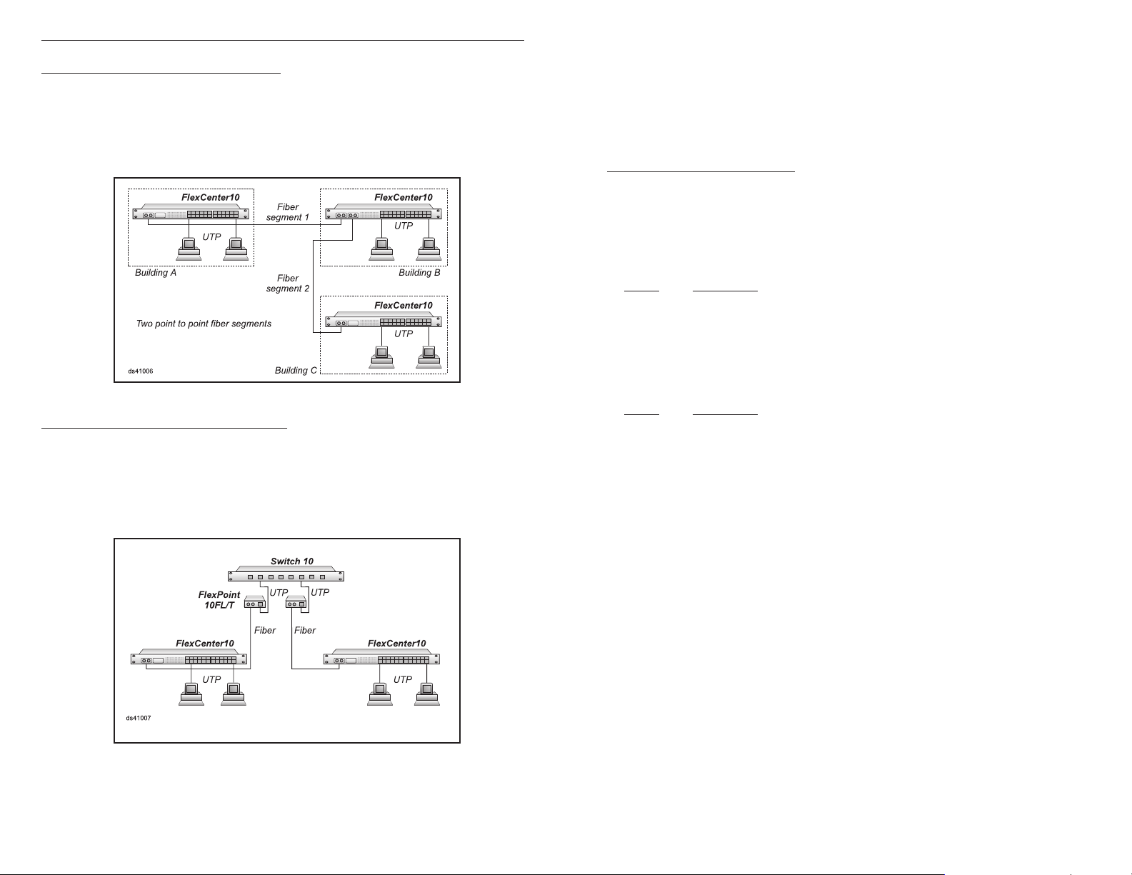
Application 6. Multiple fiber backbone
This case depicts three 10Base-T hubs interconnected using two fiber segments.
The collision rule is met (4-3-0) while restricting each fiber segment to 500 m. A
detailed calculation reveals (not provided here) that a total budget of 3,250 m of fiber
is available which would allow for instance for one of the fibers to be at 2 km while the
other could be 1,250 m.
Application 7. Switched fiber backbone
This application depicts a switched fiber backbone with the FlexCenter hubs and the
FlexPoint 10FL/T converters providing the fiber connectivity. Each "branch" segment
radiating from the switch is a separate "collision domain" and the collision rules apply
to each one independent of any other. Each one of the branching LANs meets the
collision rule (3-2-0).
FlexCenter 10
Flexible Workgroup Ethernet Hub
User Manual
GENERAL DESCRIPTION
The FlexCenter 10 is a 12/24 port 10Base-T flexible workgroup Ethernet hub repeater. It
features two optional interface modules capable of uplink interface to multimode and
single-mode fiber or coax devices or hubs.
This User’s Manual describes the following models:
Model Description
4100 12 Port 10Base-T hub, rack-mountable.
4101 12 Port 10Base-T hub, stackable.
4102 24 Port 10Base-T hub, rack-mountable.
4103 24 Port 10Base-T hub, stackable.
The following modules are supported by the FlexCenter 10:
Model Description
4110 10Base-FL Fiber uplink module, multimode, 850nm.
4111 10Base-FL Fiber uplink module, single-mode, 1300nm.
4112 10Base-FL Fiber uplink module, multimode, 1300nm.
4120 10Base-2 Coax uplink module.
The FlexCeiver’s 12/24 RJ45 ports provide 10Base-T interface to category 3 or higher
unshielded twisted pair (UTP) wiring. Its fiber interface modules provide 10Base-FL
multimode and single-mode ST connectivity options for a variety of applications. Its
coax interface module provides BNC 10Base-2 interface capability.
Being a smart repeater, the FlexCenter monitors and reports port activity. It detects
operational devices connected and displays their connection via a per port green
“Activity” LED. When sensing received data, the “Activity” LED starts blinking. If a
port violates transmission rules, it is disconnected automatically (partitioned) and a
red “Partition” LED displays the error status. The port is reconnected only after
normal behavior is restored; at that time the LED is turned off.
The hub detects and corrects polarity reversals in UTP wiring. It also detects and
displays collisions using a yellow “Collision” LED. Jabber conditions are displayed
using a red “Jabber” LED.
The FlexCenter features a special uplink RJ45 connector. This uplink connector is
equipped with a cross-over switch that can switch between the receiving and
transmitting wire pairs. This feature eliminates the need for a “Crossed Cable”
which is otherwise required when connecting between hubs.
Page 4

4 Omnitron Systems Technology, Inc.
The fiber modules feature ST fiber connections and provide “Link” activity LED, “Receiving” LED and a “Partition” LED.
The coax module features a coax BNC connector and provides “Receiving” and “Partitioned” LED displays. It also provides a switch selectable termination element which
eliminates the need for an external termination resistor when connecting at the end of
a coax line.
CONTROLS AND INDICATORS
FlexCenter 10 Mainframe:
Port 1 Control Switch
Position Description
Left Straight, use when connecting port 1 to a PC or workstation.
Right Crossed-Over, use when connecting port 1 to another hub.
Common LEDs Display
Function Color/State Description
Power Yellow / ON Power applied
Jabber Red / ON Jabber condition detected
Collision Yellow / ON Collision condition detected
Omnitron Systems Technology, Inc. 9
Per Port LEDs Display
Function Color/State Description
Link Green / ON Operational device detected at the far end of
the UTP.
Rx Green / Blink Received data on UTP line.
Par Red / ON Port partitioned due to illegal behavior .
FlexCenter 10FL Fiber Modules:
LEDs Display
Function Color/State Description
Link Green / ON Operational device detected at the far end of
the UTP.
Rx Green / Blink Received data on UTP line.
Par Red / ON Port partitioned due to illegal behavior .
Application 5. Single fiber backbone
In this case, two buildings are connected using a 2 km fiber . The LAN in building A
is interconnected via UTP and the LAN in building B is interconnected via coax. The
collision rule is met (5-4-1) with a fiber distance limit at 500 m. A detailed calculation
(not provided here) reveals that the 2 km fiber may be used.
Page 5

8 Omnitron Systems Technology, Inc.
Omnitron Systems Technology, Inc. 5
Application 2. Midsize workgroup with fiber workstations
In this case two hubs are connected via uplink cables to a third hub. Six workstations
are connected via fiber to the hubs. The longest collision path is between two stations
connected to each of the lower hubs. In this case there are 4 segments, 3 repeaters
and 0 shared segments (4-3-0). Therefore, limiting the fiber runs to 400 m satisfies
the collision rule's requirements.
Application 3. Midsize workgroup with coax segments
In this case the FlexCenter provides the central connection point among the coax and
UTP segments. Note that the coax lines are terminated by the hub's coax modules. The
longest collision path is between any two stations: 2 segments, 1 repeater and 2 shared
segments (2-1-2); the collision criteria is met.
FlexCenter 10B2 Coax Module:
Termination Switch
Position Description
Left T ermination In; use when at the end of a coax line (an external termina-
tor MUST NOT be connected.
Right T ermination Out; use when in any position except at the end of a coax
line.
LEDs Display
Function Color/State Description
Link Green / ON Operational device detected at the far end of
the UTP.
Rx Green / Blink Received data on UTP line.
Par Red / ON Port partitioned due to illegal behavior .
SITE PREP ARATION
The following are minimal physical location preparations needed:
a. Power - A power outlet should be available within 5 feet of the unit.
b. Cabling - The following cabling should be used:
1. 10Base-T / UTP - Ideally the site should be cabled with category 5 wiring but a
category 3 or better is acceptable to maximize performance (100 ohms,
24 AWG solid copper).
2. 10Base-2 / coax - Use an RG-58A/U, RG58C/U, RG58U or equivalent
(50 ohms, BNC connector).
3. 10Base-FL / Fiber - Use 50/125, 62.5/125 or 100/140 micron multimode fiber
or 9/125 micron single-mode fiber.
Application 4. Shared and dedicated coax backbones
In these two cases, three wiring closets are connected via a coax backbone. In the first
case, a coax is daisy-chained among the hubs. The maximum length of the coax
segment is 185 m (606 ft.) and the collision rule is met (3-2-1). In the second case, by
using two point to point coax segments the distance of each segment can reach 185 m
(606 ft.). The collision rule is met (4-3-2).
UNP ACKING
a. Visual Inspection - before unpacking, a visual inspection should be conducted in
order to detect any physical damage to the equipment. Any evidence of damage
should be noted and reported immediately.
b. Unpacking - place shipping container on a flat surface, cut straps or tape, open
top. Take out each item carefully and place securely on a clean flat surface. Return all packing material into container (foam, boxes etc.), close and store away
for future reuse.
c. Inspection - Inspect each item for any apparent damage. Any evidence of damage
should be noted and reported immediately.
Page 6
6 Omnitron Systems Technology, Inc.
Omnitron Systems Technology, Inc. 7
INVENTORY
Review content; the following items should be included:
(1) FlexCenter 10 unit.
(1) Power cord.
(1) User’s Manual (this document).
In rack-mounted versions (models 4100 and 4102), the rack mounting hardware may
be an integral part of the FlexCenter’s chassis or it may be included separately:
(1) Mounting ears kit.
Please note any missing items or discrepancies and report them immediately.
INST ALLATION
Cabling and Power-Up
a. Plug the power cord into the FlexCenter10 and the other side to the appropriate AC
wall outlet. The unit power light should turn ON.
b. Plug any Ethernet 10Base-T workstations into the RJ45 connectors. The corre-
sponding Link LED should turn ON.
APPLICATIONS
The 5-4-3 Collision Rule
Collisions are an inherent part of Ethernet. Since a sending station may transmit at any time,
its transmission may collide with transmissions from other stations. When a collision is
detected, the sending station backs off, waits awhile and attempts to retransmit again. This
retransmission process is very efficient when performed by hardware. In a large network, if
the delay between two stations is too long, a collision may occur without the sending station's
hardware detecting it Typically, a software function detects the loss of the sent data and
initiates a retransmission process. This retransmission process is very inefficient when
performed by software. The 5-4-3 collision rule was defined by the IEEE 802.3 standard as a
set of criteria that when followed, will ensure the detection of collisions by hardware. The
following paragraphs summarizes the main criteria points.
The main criterion dictates that two stations (DTEs) should not be separated by more than 5
segments and 4 repeaters. When in the maximum configuration the following restrictions
apply: (a) No more than 3 of the segments should be of shared (e.g. coax) type. (b) No fiber
segment should exceed 500 m.
When two stations are separated by 4 segments and 3 repeaters the following restrictions
apply: (a) Inter-repeater fiber segments should not exceed 1000 m. (b) Station to repeater
segments should not exceed 400 m. There are no restrictions on using shared segments.
The 5-4-3 rule is an approximation. In large networks, or when specific distances are
required, the reader is encouraged to use the IEEE 802.3 detailed calculation guidelines
(not described here) or consult Omnitron's application engineering staff to assist in
proper network design.
c. Connect port 1 to a workstation or another hub. When connecting to a workstation
set the Cross-Over switch to its left (Straight) position (factory setting). When
connecting to another hub set the switch to the right (Crossed) position. When the
device at the far end has become active, the port 1 Link LED should come ON.
d. Connect any fiber uplink cables to a fiber workstation, converter or another fiber hub.
Connect the Transmit (Tx) fiber of the FlexCenter to a Receive (Rx) fiber on the
connected device. Connect the Receive (Rx) fiber of the FlexCenter to a transmit
(Tx) fiber on the connected device.
e. Connect any coax uplink cables. When connecting in the middle of a coax cable,
use a “T” connector and set the Termination switch to the right (Termination Out)
position (factory setting). When connecting the FlexCenter at the end of the coax
line, connect the cable directly to the BNC connector and set the T ermination switch
to the left (Termination In) position.
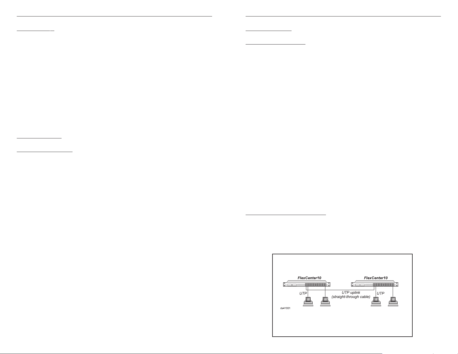
Application 1. Small workgroup
This application depicts a basic 10Base-T two-hub configuration. The hubs are
connected via a straight-through UTP patch cable with one hub selecting the "crossed
uplink" switch position. The 5-4-3 rule is met since only 3 segments, 2 repeaters and
0 shared media segments are used (3-2-0).
 Loading...