

Page 1
iConverter XG+
Standalone Module User Manual
Product Overview
The iConverter XG+ (8599R-xx-x) is a protocol-transparent ber media converter with two
pluggable transceiver ports supporting data rates from 6G to 11.32G. The iConverter XG+
can be used as a ber mode converter, a WDM transponder or a ber repeater supporting
the three Rs (regeneration, retiming and reshaping). The XG+ auto-detects the speed of
the installed transceiver.
The iConverter XG+ supports tunable DWDM and high-power (power level 4) XFP transceivers
up to a combined power of 11.0 watts. Power level 4 XFP transceivers typically perform OTN
functions, where error correction is required to achieve distance requirements. Typically,
most single-mode applications will require power level 2 or power level 3 XFP transceivers.
The iConverter XG+ supports any combination of SFP+ or XFP Power Level transceivers.
Refer to the data sheet for more information on the power level requirements.
Installation Procedure
1) Congure DIP-switches
2) Install Standalone Module and Connect Cables
3) Verify Operation
1) CONFIGURE DIP-SWITCHES
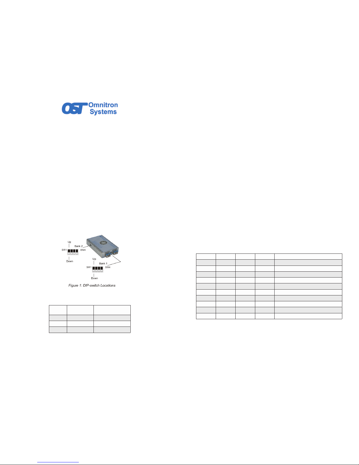
The location of the DIP-switches is shown in Figure 1.
DIP-SWITCH BANK 1
The function of DIP-switch Bank is outlined in Figure 2.
Switch
DOWN
(Default)
UP
SW1 Normal P1 Loopback Enabled
SW2 Normal P2 Loopback Enabled
SW3, SW4 Reserved Reserved
Figure 2: DIP-switch BANK 1 Denitions
Page 1
The XG+ supports port loopback. The SFP+/SFP+ XG+ supports loopback on each individual
port or simultaneous loopback on Port 1 and Port 2. The SFP+/XFP and the XFP/XFP XG+
supports loopback on each individual port, and does not support simultaneous loopback.
In all cases, both transceivers must be installed in the XG+ for the loopback feature to operate.
SW1 - P1 LOOPBACK “P1-LB”
When this DIP-switch is in the DOWN position (factory default), Port 1 (P1) loopback is
disabled. When this DIP-switch is in the UP “P1-LP” position, loopback is enabled on P1.
When enabled, all data received on P1 is transmitted out P1 and all data received on Port 2
(P2) is dropped. No data is transmitted on P2 when loopback is enabled on P1.
NOTE: For XFP models, the loopback feature is dependent on the capability of the
installed XFP. XFPs with XFI-side Loopback feature are required.
SW2 - P2 LOOPBACK “P2-LB”
When this DIP-switch is in the DOWN position (factory default), P2 loopback is disabled. When
this DIP-switch is in the UP “P2-LP” position, loopback is enabled on P2. When enabled, all
data received on P2 is transmitted out P2 and all data received on P1 is dropped. No data
is transmitted on P1 when loopback is enabled on P2.
NOTE: For XFP models, the loopback feature is dependent on the capability of the
installed XFP. XFPs with XFI-side Loopback feature are required.
SW3, SW4 - Reserved
These switches are reserved and must be in the LEFT/DOWN default position.
DIP-SWITCH BANK 2
SW1,SW2, SW3 and SW4 - LINK MODES and CIRCUIT TEST
LINK MODES
These four DIP-switches congure the different link modes available on the XG+. It is
recommended to have link modes set to Link Segment (default setting - all DOWN) during
the initial installation. After the circuit has been tested and operational, congure the module
for the desired mode. Refer to Figure 3 for conguration options.
SW1 SW2 SW3 SW4 Function
DOWN DOWN DOWN DOWN Link Segment (default)
UP DOWN DOWN DOWN Asymmetrical Link Propagate P1 to P2
DOWN UP DOWN DOWN Asymmetrical Link Propagate P2 to P1
UP UP DOWN DOWN Dual Asymmetrical Link Propagate
DOWN DOWN UP DOWN Remote Fault Detect for P1 and P2
UP DOWN UP DOWN RFD + Asymmetrical LP P1 to P2
DOWN UP UP DOWN RFD + Asymmetrical LP P2 to P1
UP UP UP DOWN RFD + Dual Asymmetrical LP
DOWN DOWN DOWN UP Symmetrical Fault Detect (SFD)*
UP UP UP UP Self Diagnostic Circuit Test
Figure 3: DIP-switch BANK 2 Link Mode and Self Diagnostic Circuit Test Congurations
* Symmetrical Fault Detect requires bookend conguration of two iConverter XG+s connected
via Port 1. For detailed information on the operation of the different Link Modes, download
the application note “iConverter Link Modes” available on Omnitron’s web page:
http://www.omnitron-systems.com/downloads_iconverter.php
Page 2
Page 2

Page 3
SELF DIAGNOSTIC CIRCUIT TEST (SFP+ models only)
When two XG 8599P or XG+ 8599R converters are connected via Port 1 (Port 1 to Port 1),
a self diagnostic circuit test is supported. To initiate a self diagnostic circuit test, only one
XG+ must be congured.
The XG+ initiating the circuit test (all DIP-switches to UP) will generate and send a test pattern
out Port 1 to the other XG+. The receiving XG+ will detect a good test pattern and return the
test pattern back to the initiating XG+.
A successful test will produce a green blinking (5Hz) P1 LB LED on the initiating XG+ and a
green blinking (1Hz) P1 LB LED on the receiving XG+. If the initiating XG+ does not receive
a valid response, the P1 LB LED will be blinking amber (5Hz). When the self diagnostic
circuit test is initiated, the trafc received on Port 2 of both XG+ converters will be discarded.
If loopback has been initiated, self diagnostic circuit test DIP-switch will be ignored. If self
diagnostic circuit test has been initiated, loopback DIP-switches will be ignored.
NOTE: The self-diagnostic circuit test on the 8599-0x and 8599N-0x are not compatible with
the self-diagnostic circuit test on the 8599P-0x and 8599R-0x.
2) INSTALL STANDALONE MODULE AND CONNECT CABLES
a. The XG+ is available in tabletop and wall-mount models. For wall-mounting, attach the
XG+ to a wall, backboard or other at surface. For tabletop installations, place the unit
on a at level surface. Attach the rubber feet to the bottom of the XG+ to prevent the
unit from sliding. Make sure the unit is placed in a safe, dry and secure location. Do not
cover the fan or any ventilations holes on the XG+ during the installation.
To power the unit using the AC/DC adapter, connect the AC/DC adapter to an AC outlet.
Then connect the barrel plug at the end of the wire on the AC/DC adapter to the 2.5mm
DC barrel connector (center-positive) on the unit. Conrm that the unit has powered up
properly by checking the power status LED located on the front of the unit.
To power the unit using a DC power source, prepare a power cable using a two conductor
insulated wire (not supplied) with a 14 AWG gauge minimum. Cut the power cable to the
length required. Strip approximately 3/8 of an inch of insulation from the power cable
wires. Connect the power cables to the unit by fastening the stripped ends to the DC
power connector.
Connect the power wires to the DC power source. The Power LED should indicate the
presence of power.
WARNING: Note the wire colors used in making the positive and negative connections.
Use the same color assignment for the connection at the DC power source.
NOTE: If mounting with a safety ground attachment, use the safety ground screw at the
rear of the unit.
b. Insert the appropriate XFP or SFP/SFP+ transceiver into the corresponding port
receptacle on the XG+. The release latch of the transceiver must be in the closed
position before insertion.
c. Connect an appropriate multimode or single-mode ber cable to the ber transceiver
ports on the XG+. It is important to ensure that the transmit (Tx) is attached to the receive
side of the device at the other end and the receive (Rx) is attached to the transmit side.
NOTE: BOTH TRANSCEIVERS MUST BE INSTALLED FOR THE XG+ TO PROPERLY
FUNCTION. WHEN ONLY ONE TRANSCEIVER IS INSTALLED AND THERE IS NO
TRANSCEIVER INSTALLED IN THE OTHER PORT, THE TRANSMITTER OF THE
INSTALLED TRANSCEIVER IS DISABLED.
3) VERIFY OPERATION
Once the module has been installed and congured per steps 1 and 2, verify the module is
operational by viewing the LED indicators.
NOTE: THE XG+ P1 AND P2 LINK LEDS (LK) WILL TURN ON (GREEN) WHEN BOTH
TRANSCEIVERS ARE INSTALLED AND PROPERLY CABLED TO THE CONNECTED
EQUIPMENT. THIS IS AN INDICATION THAT THE OPTICAL (LIGHT) CONNECTION
IS GOOD, BUT NOT NECESSARILY AN INDICATION THAT THERE IS DATA BEING
TRANSMITTED OR RECEIVED.
THE USER WILL RECEIVE CONFIRMATION OF DATA FLOW BY CHECKING TO SEE IF
THE LINK LED IS ILLUMINATED ON THE CONNECTED EQUIPMENT.
Legend OFF State Color ON/Blinking State
Pwr Off – No power Green Green – Power On
P1/P2
Lk
Off – No Transceiver detected
or no ber link
Green
Green Solid – Fiber link
Green Blinking (1/2Hz) – When SFD is enabled,
receiving remote ber fault signal from link partner
P1/P2
Stat
Off – Transceiver does not
support digital diagnostic or
no transceiver installed
Green
Green Solid – Transceiver supports digital
diagnostic and no DDMI Alarm Detected
Amber
Amber Solid – Transceiver supports digital
diagnostic and DDMI alarm detected
P1 LB
Off – Port loopback mode not
enabled or congured
Green
Green Solid – Port set to Loopback mode and port
in loopback
Green Blinking (1 Hz) - Port responding to Circuit
Test activation with valid Circuit Test response
Green Blinking (5 Hz) - Port initiating Circuit Test
and receiving valid Circuit Test response
Amber
Amber Solid – Port set to loopback mode, but XFP
does not support loopback
Amber Blinking (5 Hz) - Port initiating Circuit Test
and not receiving valid Circuit Test response
P2 LB
Off – Port loopback mode not
enabled or congured
Green
Green Solid – Port set to Loopback mode and port
in loopback
Amber
Amber Solid – Port set to loopback mode, but XFP
does not support loopback
P1 Lk, P1
Stat,
P2 Lk, P2
Stat
- Amber
Simultaneous Amber Blinking (1Hz) – Ports disabled
due to unsupported power level of the installed
XFP transceiver. Module drawing more current than
allowed
Figure 4: LED Indicators
XG 8599R-xx NOTE:
The XG+ does not generate data, it only passes the data it receives from the connected
equipment. So both transceivers must be installed and connected in order for the
module to pass data trafc. P1/P2 Lk LED indicates an optical connection has been
established. It does not indicate the presence of data trafc.
040-8599R-001B 6/18
Omnitron Systems Technology * 38 Tesla * Irvine, CA 92618
949.250.6510 tel * 949.250.6514 fax * www.omnitron-systems.com
© 2018, Omnitron Systems Technology, Inc.
 Loading...