

Page 1
Omnitron Systems
............................................................................................................
T echnology, Inc.
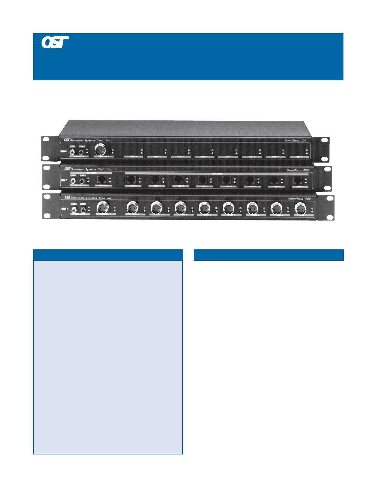
OmniMux™ 400
AS400/3X 5250 and 5250 Express Multiplexer
FEATURES DESCRIPTION
Twinax 5250 and 5250 Express compatible multiplexer
that concentrates AS/400 or system 3X twinax cables
and delivers them to distances up to 25,000 feet via a
fiber pair, twisted pair or a single twinax.
Seamlessly connects to IBM AS/400 and 3X local and
remote twinax controllers and workstations.
Operates with traditional twinax cabling or modern
fiber and twisted pair wiring.
Retiming repeater technology regenerates and reclocks
data, eliminating clock jitter and noise.
Digital Phase Locked Architecture provides acquisition
of data rates of 1 Mbps for 5250 or 2 Mbps for 5250
Express (-2%, +4%), resulting in high immunity to
noise and crosstalk.
Twinax or RJ11/45 connectors and polarity controls
provide easy installation and flexibility.
Clear display and software independence make
installation and monitoring intuitive and easy.
The OmniMux™ 400 is an IBM compatible multiplexer that
provides part or full local or remote 5250 and 5250 Express twinax
controller connectivity to a distant location. It replaces up to
eight AS/400 twinax cables with a single link. This link may be a
twinax, twisted pair or a multimode or single-mode fiber pair.
Optionally , the OmniM ux can eliminate the twinax distribution
box ("brick") and provide a direct single cable connection to the
host controller, r eplacing all host controller twinax with a single
DB25 cable. The OmniM ux supports up to 56 addresses per link.
The OmniMux operates as a multiplexer (M ux), a demultiplexer
(Demux), a demultiplexer-star (Demux-Star) or a star.
In the Mux and Demux modes, the OmniM ux operates in pairs.
On the host side, the Mux is connected to the local or remote
controller’s twinax connectors, concentrating their twinax ports
into a single link. At the far end, the Demux recreates each host
port. Each port behaves as the original host port it is recreating.
It can connect to the distant workstations via twinax daisy chains,
twisted pair star hubs, such as the OmniStar™, or via fiber to
desk repeaters, such as the OmniRepeater™ FTD.
Omnitron Systems Technology, Inc. • 140 Technology Dr., Suite 500 • Irvine, CA 92618 • 949.250.6510 tel. • 949.250.6514 fax • www.omnitron-systems.com
Page 2
In the Star mode, the OmniM ux delivers twisted pair or twinax
connectivity to the workstation while providing fiber connectivity
back to the host end. The fiber conversion at the host end can be
TM
done using any OmniRepeater
fiber converter.
The Demux-Star mode is used for multi-drop applications, when
seven or less workstations at the far end are required. In this
configuration, the OmniMux with an OmniM ux XL multi-port
mux supports the multi-drop requirement and allows a single
host port to be selected for delivery to the far end.
The OmniMux utilizes a Digital Phase Locked Architecture
(PLA). It facilitates data synchronization of data rate variations
of up to -2% to +4%. It also facilitates a high degree of noise and
crosstalk immunity . Each port is monitored and each data packet
is analyzed for validity and errors. Noisy, shorted or open ports
are automatically ignored and only valid data is processed. The
retransmitted data is repeated, regenerated and reshaped; this
ensures its reliable delivery to its destination.
The Express models operate with both the 5250 and 5250 Express
protocols. Each port provides data rates of 1 Mbps for standard
5250 and 2 Mbps for 5250 Express protocol.
The host and workstations can be connected via twinax, RJ11/45
twisted pairs or a 25-pin DB25 cable. The twisted pair polarity
control allows interface to different baluns.
Processing: Once the data has been reco vered and synchronized,
it is processed internally for validity. The processor analyzes the
Frame Header, expecting at least 3 Sync bits followed by a Code
Violation. When a legal Frame Header is detected, the port is
“marked” active and the data is allowed to be retransmitted.
Outputs: The retransmitted data is fully regenerated and
reclocked. Lost sync bits are restored, and the data is reclocked at
a 50% duty cycle, eliminating any accumulated phase shift and
clock jitter. The regenerated signal is restored to its nominal shape
and amplitude and the pre-distortion logic compensates for
anticipated phase shift and attenuation.
Displays: P er port true data activity and parity errors are displayed
by green and red LEDs. The green activity LEDs assist in
monitoring signal strength and polarity. The red Parity Error
LEDs assist in monitoring connectivity quality, signal strength,
impedance mismatches and reflections.
Auto Link Backup: Utilizing two links simultaneously pro vides
link redundancy. The primary F/O link can be backed up by a
“Standby” twinax or UTP link. Switching between the primary
and secondary links is done automatically by the hardware. The
Activity LEDs report the activity of each link.
Utilizing two links simultaneously provides a hot backup
connection for fault tolerance in critical applications.
The OmniMux diagnostics detect and display true port activity
and parity errors. Each port is monitored for valid frame header
patterns, a detected pattern is displayed via a per-port green
Activity LED. The data is analyzed for parity errors; a detected
error is displayed via a per-port red Error LED. These features
assist in installation and monitoring of the OmniMux operation.
The OmniMux
400 is completely software transparent and no
setup or any changes are required.
OPERATION
Inputs: The OmniMux 400 is built around a Digital Phased
Locked Architecture (PLA). It allows the independent monitoring
and processing of data signals at each individual port,
discriminating between true data and noise. A priority mechanism
increases isolation between individual ports, reducing any
crosstalk effect. The incoming M anchester encoded data is oversampled at a rate of 16 samples per bit cell. This sampling rate is
instrumental in the digital filtering of noise. A unique clock
extraction technology facilitates the synchronization to data, with
frequency variations of -2% to +4%.
SAMPLE APPLICATIONS
The following illustrations depict several sample applications of
the OmniMux 400:
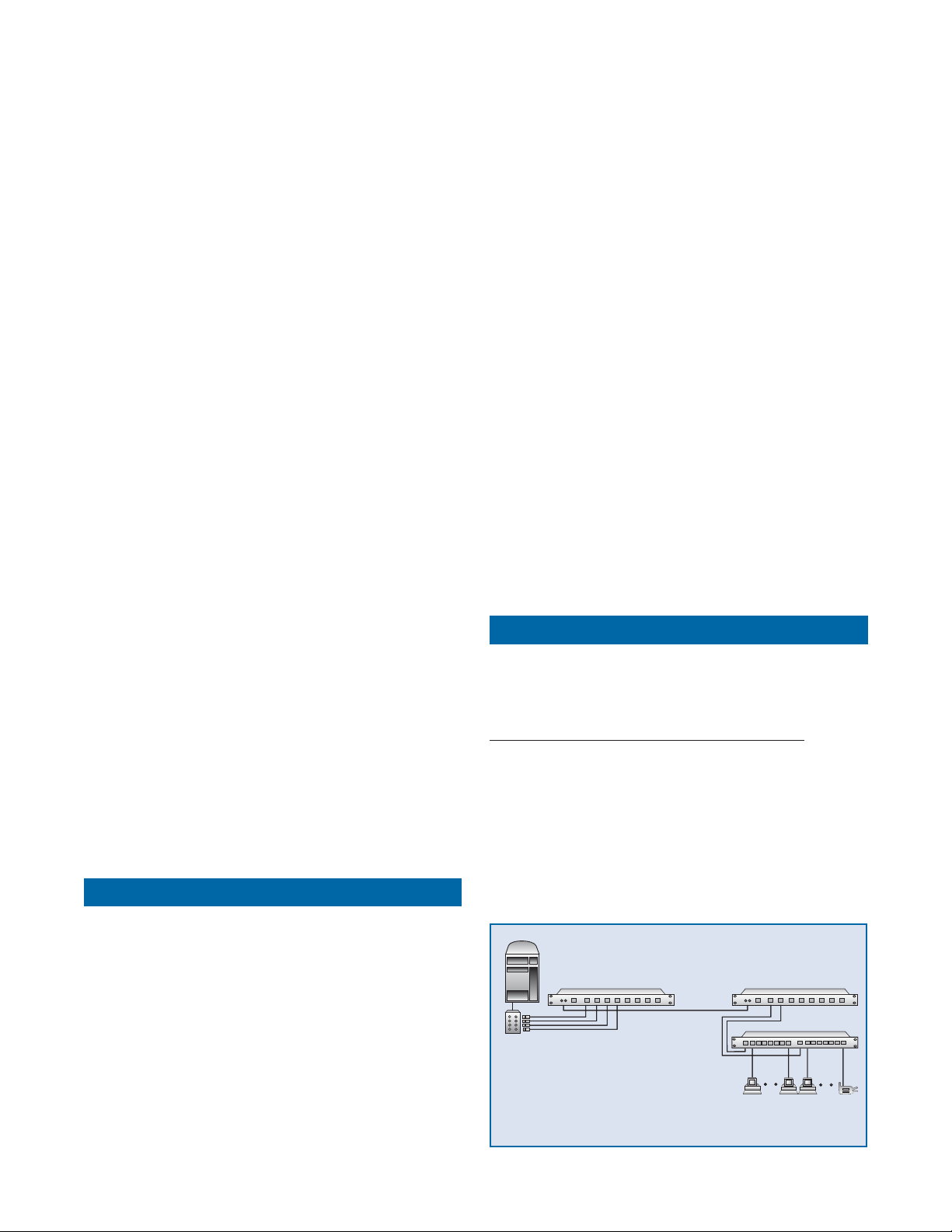
Application 1. Standard Local Controller E xtension
In this application, four AS/400 controller ports must be extended
via fiber across a campus to a second building.
The host (a) is connected to the Mux (c) using baluns and UTP
cabling (b). A fiber optic cable (d) connects to the Demux (e)
which connects each port to a UTP star that provides UTP
connectivity to each workstation (f).
AS/400
AS/400
(a)
(a)
(c) Mux
(c) Mux
OmniMux 400
twinax
twinax
"brick"
"brick"
ds27001
ds27001
(b) baluns and
(b) baluns and
twisted pair
twisted pair
wiring (UTP)
wiring (UTP)
OmniMux 400
(d) fiber
(d) fiber
(e) Demux
(e) Demux
(f) UTP to workstations
(f) UTP to workstations
OmniMux 400
OmniMux 400
OmniStar 400
OmniStar 400
Omnitron Systems Technology, Inc. • 140 Technology Dr., Suite 500 • Irvine, CA 92618 • 949.250.6510 tel. • 949.250.6514 fax • www.omnitron-systems.com
Page 3
Application 2. Remote Controller Extension
AS/400
OmniStar 400
OmniMux 400
OmniMux 400
(a)
(b) DB25 cable
(d) fiber
(e) Demux(c) Mux
(f) UTP to workstations
OmniStar 400
(g) UTP to workstations
ds27005
Application 4. Multi-Drop Demux-Star Layout
In this application an existing twinax cable, which is used to
connect a single port with seven workstations, is being reused to
increase the number of ports at a distant site to four and service
up to 28 workstations. The workstations at the far end ar e to be
connected via twinax.
In this implementation, a 5494 type remote controller (a) is
connecting the four twinax ports (b) to the Mux (c) which
concentrates them onto the existing twinax link (d). The twinax
link cable connects to the far end Demux (e) where the original
ports are regenerated and provide connectivity to the 28
workstations. As required the workstations are connected via
twinax directly from the Demux.
In this example, several buildings across a campus are required
to be connected to the host via fiber. Some use one por t with
fewer than seven devices and others use multiple ports with more
than seven devices.
In this case an OmniMux 400XL (c) is connected via a DB25 (b)
cable to the host (a) and provides the central fiber distribution
point with each fiber link being able to connect any number of
ports. The example shows one fiber (d1) connecting to a regular
Demux (e1) with two ports connecting to its end workstations
via twinax (f1) and a second fiber connecting to a Demux-Star
(e2) servicing a single port directly from its UTP ports (f2).
AS/400
(a)
(b) DB25 cable
OmniMux 400
(c) SuperMux
(d1) fiber
(d2) fiber
(e1) Demux
(f1) twinax to
workstations
(e2) Demux-Star
OmniMux 400
OmniMux 400
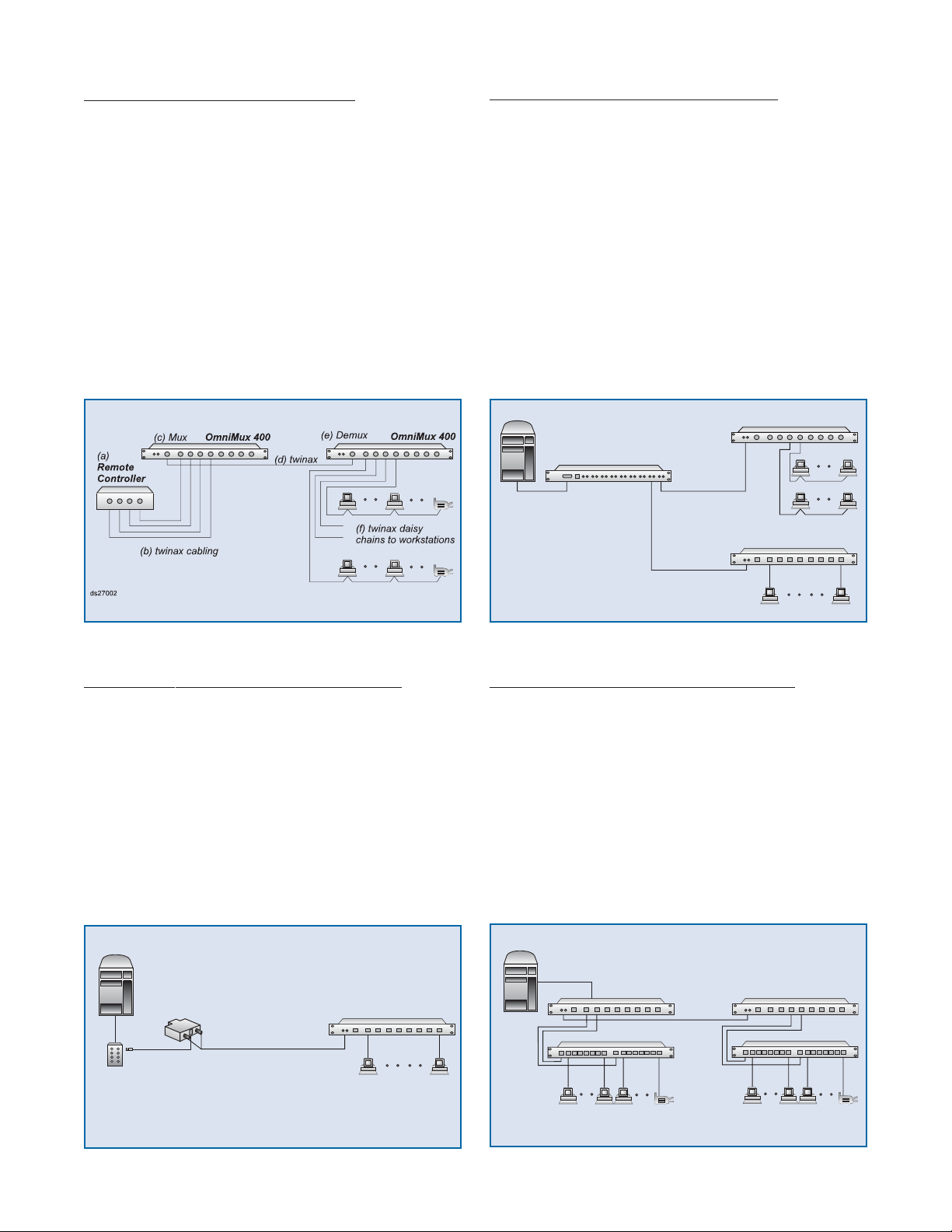
Application 3. The OmniMux As a Fiber Optic Star
In this example, a low-cost solution is desired for connecting a single
AS/400 host port via fiber to a twisted pair distribution star.
In the proposed implementation, the host (a) twinax port which
originates at the local controller's distribution “brick” is converted
into twisted pair via an impedance matching balun. The UTP
wire is converted into fiber (d) using an OmniRepeater 400FTD
(c). The fiber connects the far end OmniMux (e) which is
operating in a fiber star mode and connects to each workstation
(f) via UTP cables.
AS/400
(a)
(e) Fiber Star
ds27003
(c)
(b) balun to UTP
(d) fiber
OmniMux 400OmniRepeater 400FTD
(f) UTP to
workstations
(f2) UTP to
ds27004
workstations
Application 5. DB25 and Local P ort Connectivity
In this case it is required to minimize twinax cabling at the
host end and connect UTP workstations at the host and at
the distant ends.
T o minimize cabling, a single DB25 (b) cable replaces the "brick"
and all twinax cables, and connects the host (a) to the Mux (c).
The local workstations (g) are connected via a local star . The far
end Demux (e) is connected via the fiber link (d) and the far end
workstations (f ) are connected to the Demux via a star. Note
that the two stars use different host ports from their Muxes.
Omnitron Systems Technology, Inc. • 140 Technology Dr., Suite 500 • Irvine, CA 92618 • 949.250.6510 tel. • 949.250.6514 fax • www.omnitron-systems.com
Page 4

SPECIFICATIONS
Protocol: IBM 5250 and 5250 Express for systems
AS400 and 3X
Devices Supported: All twinax IBM / compatible
devices (terminals and printers)
Interface:
Host/Device: Eight (8) Twinax or
Eight (8) Twinax and DB25 or
Eight (8) UTP or
Eight (8) UTP and DB25
Mux Link: Fiber Optic (pair) and Twinax or
Fiber Optic (pair) and UTP
Mating Connectors Supported:
Fiber Optic: ST
Twinax: IBM 7362229 or equivalent
UTP: RJ11 pins 3-4 active or
RJ45 pins 4-5 active
Cable Types:
Fiber Optic: 50/125,62.5/125,100/140 um
Twinax: IBM 7362229 or equivalent
UTP: Level 3 (EIA/TIA 568):
24 AWG solid copper
100 +/- 15 ohms @ 1 Mhz
7.8 db per 1000 ft. @ 1.0 Mhz
(shorter distance @ lower grade)
Data Rate:
Standard 5250: 1 Mbps -2%, +4%
5250 Express: 1 or 2 Mbps -2%, +4%
Supported Distances:
Host/Device to Mux:
Twinax: 5,000 ft.
UTP: 3,000 ft.
DB25: 50 ft.
Mux to Mux:
Twinax: 5,000 ft.
UTP: 3,000 ft.
Multimode fiber: 15,000 ft.
Single-mode fiber: 30,000 ft.
Indicators:
Power: Yellow LED (1)
Activity Green LED (10)
Parity Error: Red LED (10)
Physical features: Rackmounted
Dimensions: W:19.0”xD:6.0”xH:1.75”
Weight: 8 lbs.
Power: 115 or 230 VAC, 150 mA
Temperature:
Operating: 0 to 40 degrees C
Storage: -40 to 75 degrees C
Humidity: Up to 90% (non condensing)
ORDERING INFORMATION
Standard 5250 Standard 5250 5250 Express 5250 Express
Multimode Fiber Single-Mode Fiber Multimode Fiber Single-Mode Fiber Description
2700 2740 8 Ports, RJ11/45 to F/O and RJ11/45
2701 2741 8 Ports, TWX to F/O and TWX
Models Discontinued as of January 2009
2720 2760 8 Ports, RJ11/45 to F/O and RJ11/45
2721 2761 8 Ports, TWX to F/O and TWX
2702 2722 2742 2762 4 Ports, RJ11/45 to F/O and RJ11/45
2703 2723 2743 2763 4 Ports, TWX to F/O and TWX
2704 2724 2744 2764 2 Ports, RJ11/45 to F/O and RJ11/45
2705 2725 2745 2765 2 Ports, TWX to F/O and TWX
2710 2730 2746 2766 8 Ports, RJ11/45 and DB25 to F/O and RJ11/45
2711 2731 2747 2767 8 Ports, TWX and DB25 to F/O and TWX
2750 2771 2748 2768 8 Ports, DB25 to F/O and TWX
9100-DB25-30 DB25 Cable, 30 feet
Legend
TWX = Twinax, F/O = Fiber Optic
Trademarks are owned by their respective companies
OmniMux, OmniStar, OmniRepeater are trademarks of
Omnitron Systems Technology, Inc.
Specifications subject to change without notice.
©2009 Omnitron Systems Technology , Inc.
091-02700-002C 1/09
140 Technology Dr. Suite 500, Irvine, CA 92618
Tel: (949) 250-6510 Fax: (949) 250-6514
E-mail: info@omnitron-systems.com
http://www.omnitron-systems.com
 Loading...