

Page 1
+
-
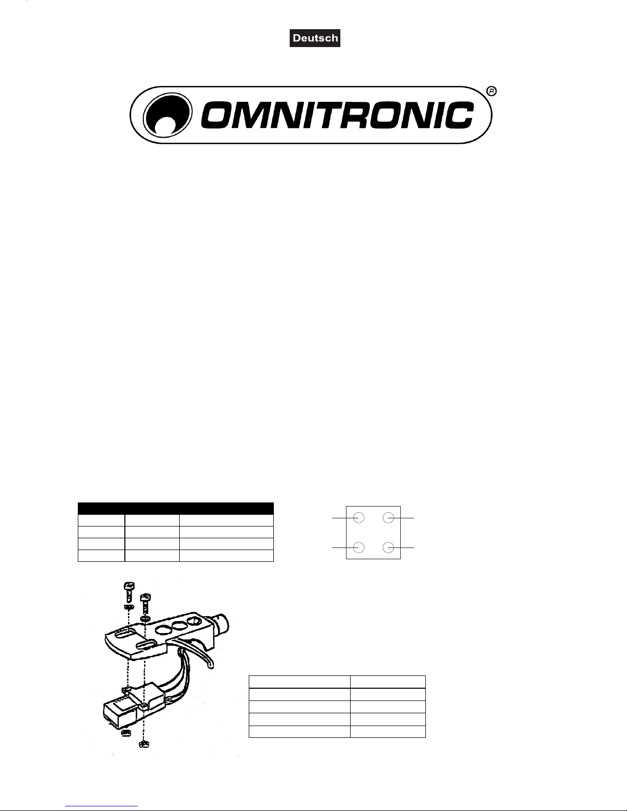
LR
1
2
3
4
MONTAGEANLEITUNG
S-15
Tonabnehmersystem
ANWENDUNGSBEREICH
Dieses Tonabnehmersystem wird empfohlen für OMNITRONIC BD-1550, DD-2220, DD-2250, DD-4220,
DD-4250
LIEFERUMFANG
Sie erhalten den Tonabnehmer mit Schutzkappe, 2 Befestigungsschrauben, 2 Kontermuttern und 2 Unterlegscheiben.
INSTALLIEREN/AUSTAUSCHEN DES TONABNEHMERSYSTEMS
Wenn Sie das System austauschen, lösen Sie die Befestigungsschrauben an der Headshell und ziehen Sie
die Verbindungskabel des Tonabnehmersystems ab. Enfernen Sie das alte Tonabnehmersystem aus der
Headshell.
Setzen Sie den Nadelschutz auf, damit die Nadel nicht beschädigt werden kann.
Verbinden Sie die Anschlussdrähte der Headshell mit den Anschlussstiften des Tonabnehmersystems und
achten Sie darauf, dass die Belegung der Drähte übereinstimmt.
Die verschiedenen Farben bedeuten:
Pin-Nr.: Farbe: Kanal und Polung
1 Weiß (L+) Links, Plus-Pol
2 Blau (L-) Links, Minus-Pol
3 Rot (R+) Rechts, Plus-Pol
4 Grün (L-) Rechts, Minus-Pol
Nach der Montage der Verbindungsleitungen befestigen Sie den
Tonabnehmer mit den beiliegenden Schrauben unter dem
Systemhalter.
Balancieren Sie den Tonarm aus und stellen die Auflagekraft/AntiSkating ein (Empfohlenes Auflagegewicht 2,5 g )
TECHNISCHE DATEN
Gewicht: 5 g
Frequenzgang: 20 - 20 000 Hz
Empf. Auflagekraft: 30 mN
Ausgangsspannung: 5 mV
Abschlusswiderstand: 47 kOhm
Page 2
+
-
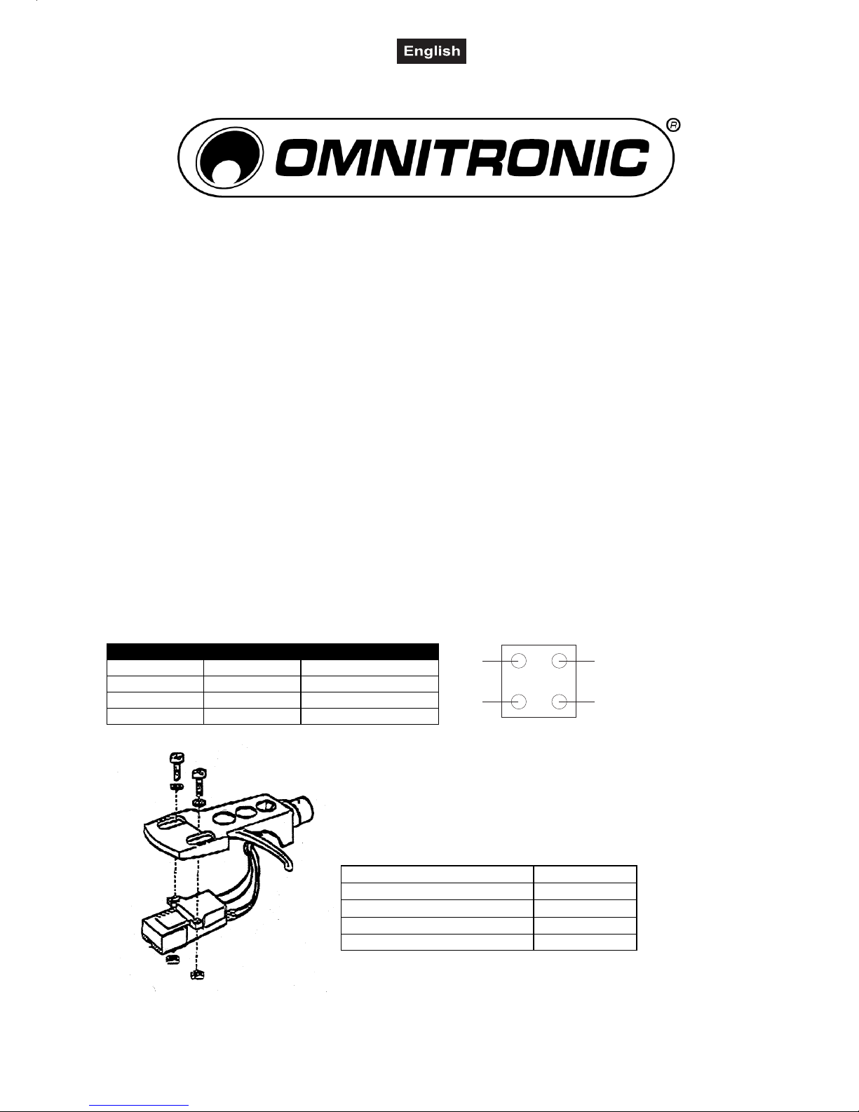
LR
1
2
3
4
INSTALLATION INSTRUCTIONS
S-15
Pick-up-system
USAGE
This pick-up-system is recommended for OMNITRONIC BD-1550, DD-2220, DD-2250, DD-4220, DD-4250
DELIVERY
The delivery includes the pick-up-system with stylus cover, 2 fixation screws, 2 nuts and 2 washers.
INSTALLING/EXCHANGING THE PICK-UP SYSTEM
If you are exchanging the system, loosen the tightening screws on the headshell and remove the connectioncables of the pick-up system. Remove the old pick-up system from the Headshell.
Put the stylus cover on the stylus.
Connect the Headshell's connection cables with the terminals of the pickup-system and make sure that the
occupation of the cables is correct.
The different colours mean:
Pin-No.: Used colour: Channel and poles:
1 White (L+) Left, plus-pole
2 Blue (L-) Left, minus-pole
3 Red (R+) Right, plus-pole
4 Green (L-) Right, minus-pole
After connecting the connection cables fix the system with the
enclosed screws under the Headshell.
Balance the tone-arm and adjust the stylus pressure/Anti-Skating
(recommended stylus pressure 2.5 g )
TECHNICAL SPECIFICATIONS
Weight: 5 g
Frequency response: 20 - 20,000 Hz
Recommended tracking force: 30 mN
Output voltage: 5 mV
Terminal resistance: 47 kOhm
 Loading...