

Page 1

Advanced Measurement Technology
Ultra
4K Tool Box
User Guide
Software Version: 1.2
January 2015
Page 2

Ultra 4K Tool Box User Guide, v1.2
© 2014 OmniTek. All rights reserved
This documentation contains proprietary information of OmniTek. No part of this documentation
may be reproduced, stored in a retrieval system or transmitted in any form or by any means,
electronic, mechanical, recorded or otherwise without the prior written permission of OmniTek.
The information contained in this documentation was prepared by OmniTek with all reasonable
care and is believed to be accurate. However OmniTek does not assume responsibility for loss or
damage resulting from omissions, inaccuracies or errors contained herein. The information
contained in this document is subject to change and revisions hereto or new additions may be
issued to incorporate such changes.
Warranty
OmniTek systems are warranted for one year from date of purchase. This includes all feature
upgrades and bug fixes to the application software, plus repair or replacement of the hardware
(at the discretion of OmniTek). Extended warranty agreements are also available, please consult
your local dealer.
Contact Information
OmniTek
Intec Unit 2.3, Wade Road, Basingstoke, Hants RG22 8NE, UK
Tel: +44 (0)1256 345900 Fax: +44 (0)1256 345901
Email: support@omnitek.tv Web: www.omnitek.tv
Conventions Used in this Guide
The following typographical conventions are used:
Convention Meaning or Use
<item> Placeholder for item of the named type
Italic font Reference to a signal
Or: reference to a separate document
Bold font Reference to a file/software package
xxxxxx Link to additional information.
Page 3

Ultra 4K Tool Box User Guide, v1.2
Contents
Section 1: General
A: Equipment Guide ................................................................................................................. A-1
A.1 Introduction .................................................................................................................. A-1
A.1.1 Safety Statement .................................................................................................. A-1
A.1.2 System Features ................................................................................................... A-2
A.1.3 Front and Rear Panels .......................................................................................... A-3
A.1.4 Instrument Options .............................................................................................. A-5
A.2 Installation .................................................................................................................... A-6
A.2.1 Preliminary steps: ................................................................................................ A-6
A.2.2 Standard Set-Up ................................................................................................... A-6
A.2.3 Set-Up Options .................................................................................................... A-7
A.3 Power Up ...................................................................................................................... A-9
A.3.1 Power Requirements ............................................................................................ A-9
A.3.2 Start-Up Procedure .............................................................................................. A-9
A.3.3 Shutting Down ................................................................................................... A-10
A.4 The User Interface ...................................................................................................... A-11
A.4.1 Button Bars ........................................................................................................ A-11
A.4.2 ‘Properties’ ........................................................................................................ A-12
A.4.3 User Interface Controls ...................................................................................... A-12
A.4.4 Keyboard Alternatives ....................................................................................... A-14
A.4.5 Presets Toolbar .................................................................................................. A-15
A.4.6 Saving Settings etc. to Disk ............................................................................... A-15
A.5 System Information .................................................................................................... A-16
A.5.1 System Details ................................................................................................... A-16
A.5.2 System Facilities ................................................................................................ A-18
A.5.3 Updating to the Latest Version .......................................................................... A-19
A.5.4 Installing Additional Facilities .......................................................................... A-19
A.5.4 Installing Additional Facilities .......................................................................... A-21
B: System Configuration & Control ........................................................................................ B-1
B.1 Inputs, Outputs & Internal Connections: the Connections window ............................. B-1
B.1.1 Making Connections ............................................................................................ B-3
B.1.2 Selecting SDI Inputs ............................................................................................ B-3
B.1.3 Selecting SDI Outputs ......................................................................................... B-4
B.1.4 Using the DisplayPort Output .............................................................................. B-4
B.1.5 Setting the Output Video Standard ...................................................................... B-4
B.1.6 Genlock ................................................................................................................ B-6
B.1.7 Analyser/Converter Filter .................................................................................... B-6
B.1.8 Connections needed to display Picture Images on a Monitor ............................. B-7
B.2 System Configuration ................................................................................................... B-8
B.2.1 Video Parameters ................................................................................................. B-9
B.2.2 System Parameters ............................................................................................. B-11
B.2.3 Licensed Facilities ............................................................................................. B-11
B.3 Presets ......................................................................................................................... B-12
B.3.1 Recording Presets .............................................................................................. B-12
B.3.2 Preset Selection .................................................................................................. B-13
B.3.3 Changing the Name of a Preset ......................................................................... B-13
B.3.4 Deleting a Preset ................................................................................................ B-13
Page 4

------------------------------------------- Contents -------------------------------------------
Ultra 4K Tool Box User Guide, v1.2
B.4 Import/Export of Settings etc. .................................................................................... B-14
B.4.1 Overview ........................................................................................................... B-14
B.4.2 Exporting Presets ............................................................................................... B-14
B.4.3 Importing Presets ............................................................................................... B-15
B.5 Remote Monitoring and Control ................................................................................ B-16
B.5.1 Set-Up ................................................................................................................ B-16
B.5.2 Programming the SNMP Manager .................................................................... B-17
B.5.3 Downloading the MIB file ................................................................................. B-17
Section 2: Conversion Facilities
D: Format Conversion .............................................................................................................. D-1
D.1 Overview ...................................................................................................................... D-1
D.2 Setting up the 4K Tool Box to carry out the Required Conversion ............................. D-2
Section 3: Signal Analysis
H: The Viewer Window ............................................................................................................ H-1
H.1 Overview ...................................................................................................................... H-1
H.1.1 Screen Layout ...................................................................................................... H-2
H.2 Viewer Window Operations ......................................................................................... H-3
H.2.1 View Selection ..................................................................................................... H-3
H.2.2 Switching between Full Screen and Multiple Tile displays ................................ H-3
H.2.3 Configuring a View ............................................................................................. H-5
H.3 Focus of Analysis ......................................................................................................... H-5
H.4 Saving and Recalling Specific Tile Selections ............................................................. H-6
J: Pixel Data ................................................................................................................................ J-1
J.1 The Focus of the Display and its Movement Pixel-by-Pixel ........................................ J-2
J.2 Data View ...................................................................................................................... J-4
J.2.1 Configuration ........................................................................................................ J-6
J.3 Cable View .................................................................................................................... J-6
J.4 Ancillary Data Viewer .................................................................................................. J-7
K: Picture View ......................................................................................................................... K-1
K.1 Overview ...................................................................................................................... K-1
K.2 Displaying Picture Images ........................................................................................... K-2
K.2.1 System Setup ....................................................................................................... K-2
K.2.2 Picture View Selection ........................................................................................ K-3
K.2.3 Display Options ................................................................................................... K-3
K.3 Cursor ........................................................................................................................... K-3
K.4 Safe Action / Safe Title Cages ..................................................................................... K-4
K.4.1 Set-Up .................................................................................................................. K-5
K.4.2 Displaying the cages ............................................................................................ K-7
K.5 Zoom View ................................................................................................................... K-8
L: Waveform Display ................................................................................................................ L-1
Page 5

------------------------------------------- Contents -------------------------------------------
Ultra 4K Tool Box User Guide, v1.2
N: Gamut Analysis .................................................................................................................... N-1
N.1 Gamut Meters ............................................................................................................... N-1
N.1.1 Setting the Permitted Ranges ............................................................................... N-2
N.1.2 Selecting the Colour Components to be Displayed ............................................. N-2
O: Status ..................................................................................................................................... O-1
O.1 The Status View ........................................................................................................... O-1
O.1.1 Selection .............................................................................................................. O-2
O.1.2 Error Ranges, Persistence and Severity ............................................................... O-2
O.1.3 Resetting Error Counts ........................................................................................ O-2
O.2 Video Information Displayed ....................................................................................... O-2
Section 4: Physical Layer Analysis
S: Eye & Jitter Measurement .................................................................................................... S-1
S.1 Overview ....................................................................................................................... S-1
S.1.1 Facilities Offered .................................................................................................. S-2
S.1.2 Set-Up ................................................................................................................... S-2
S.2 Jitter Meters ................................................................................................................... S-3
S.2.1 Selecting the Jitter Meters display ........................................................................ S-4
S.2.2 Recording the current Meter Positions ................................................................. S-4
S.2.3 Setting the Meter Scale and Colour-Transition Points ......................................... S-4
S.3 Eye Waveform ............................................................................................................... S-5
S.3.1 Selecting the Eye Waveform display .................................................................... S-6
S.3.2 Selecting the Jitter Meter that is displayed ........................................................... S-6
S.3.3 Display Colouring ................................................................................................. S-6
S.3.4 Obtaining Signal Parameters from the Eye Waveform ........................................ S-7
S.3.5 Transmission Integrity .......................................................................................... S-7
T: Timing Measurement ........................................................................................................... T-1
T.1 Overview ...................................................................................................................... T-1
T.2 Set-Up ........................................................................................................................... T-2
T.2.1 Set-Up for Measurement Against an External Reference Signal ........................ T-2
T.2.2 Set-Up to give Line-Based Timings .................................................................... T-3
T.3 Comparing the Timing of Constituent Inputs .............................................................. T-3
T.4 Comparing Timing against an External Reference ...................................................... T-4
Section 5: Generator
V: Generator Basics .................................................................................................................. V-1
V.1 The Generator Window ................................................................................................ V-1
V.1.1 Selecting the Generator Window ......................................................................... V-2
V.1.2 Controls ............................................................................................................... V-2
V.2 Creating Test Patterns from Image files ....................................................................... V-3
V.3 Playing out Test Patterns .............................................................................................. V-4
V.4 When Test Patterns/Sources are no longer required .................................................... V-5
V.5 Play-Out in Sequence ................................................................................................... V-6
Page 6

------------------------------------------- Contents -------------------------------------------
Ultra 4K Tool Box User Guide, v1.2
W: Creating Test Patterns ....................................................................................................... W-1
W.1 Line (Colour Bar) Patterns .......................................................................................... W-1
W.1.1 Adding a New Line Pattern ................................................................................ W-1
W.1.2 Configuring the Line Pattern .............................................................................. W-2
W.1.3 Modifying an existing Line Pattern .................................................................... W-3
W.2 Zone Plates .................................................................................................................. W-3
W.2.1 Adding a New Zone Plate ................................................................................... W-3
W.2.2 Modifying an existing Zone Plate ...................................................................... W-5
W.3 Combination Test Patterns .......................................................................................... W-5
W.3.1 Modifying an existing Combination Test Pattern ............................................... W-6
W.4 Saving Patterns on Disk .............................................................................................. W-6
W.4.1 Saving Patterns ................................................................................................... W-7
W.4.2 Importing Saved Test Patterns/Test Pattern Sets ................................................ W-8
W.4.3 Importing a Saved Source Image/Pattern ........................................................... W-8
X: Modifying the Output .......................................................................................................... X-1
X.1 Overview ...................................................................................................................... X-1
X.2 Resizing Images ........................................................................................................... X-2
X.3 Luma/Chroma Adjustments ......................................................................................... X-2
X.3.1 Selecting the Colour Range ................................................................................. X-2
X.3.2 Adjusting the Gamma .......................................................................................... X-3
X.4 Image Panning .............................................................................................................. X-3
X.4.1 Setting an Image to Pan ....................................................................................... X-3
X.5 Jitter Insertion ............................................................................................................... X-4
Page 7

Ultra 4K Tool Box User Guide, v1.2
Section 1: General
This section introduces the facilities offered by the Ultra 4K Tool Box, explains
how to set it up and describes how it is controlled.
It also gives general maintenance advice and describes the steps used to upgrade
to the latest version of the 4K Tool Box software and to add software options.
Note: Throughout this guide, steps are described in terms of mouse operations
such as clicking. Where the user interface to 4K Tool Box is displayed on a touchscreen device, substitute the equivalent finger actions.
Page 8

------------------------------------------- General -------------------------------------------
Ultra 4K Tool Box User Guide, v1.2
Page 9

Ultra 4K Tool Box User Guide, v1.2 A-1
A : Equipment Guide
A.1 Introduction
The OmniTek Ultra 4K Tool Box combines a video format converter capable of up/down/cross
conversion, colour and image manipulation in all current and anticipated 4K video formats up to
4096 x 2160/60, in a single box with waveform analysis and video generation across the same
range of video formats.
In doing so, it offers a complete solution to the conversion and analysis of Ultra HDTV and
Digital Cinema signals, allowing manufacturers, designers, researchers, broadcast stations,
networks, outside broadcast units and systems integrators to build, test and commission 4K
products and systems with complete confidence.
The 4K Tool Box also offers of a variety of connection formats – multi-rate SDI, HDMI and
DisplayPort – for both video source and display. Conversion between physical and image
formats allows operation in multi-format video environments, while comprehensive SDI eye and
jitter analysis features enable system designers to rapidly locate sources of signal error in all
signal paths up to 12G-SDI single link 4K.
A.1.1 Safety Statement
To avoid injury and prevent damage to the 4K Tool Box or to any products connected to it, use
this product only as specified and take the following safety precautions. Where the 4K Tool Box
is being used alongside other equipment, you must also ensure that you act in accordance with
the advice given in the documentation supplied with those other products.
Only use the power cord that is both specified for this product and certified for the
country of use.
Ensure that the product is properly grounded through the grounding conductor within the
power cord.
Ensure that it is always possible for the user to switch off the power to the unit if need be.
Keep all product surfaces clean and dry.
Ensure that the unit is properly ventilated.
Do not operate in an explosive atmosphere or in damp/wet conditions.
Do not operate the Ultra 4K Tool Box with either the cover or any of the panels removed
or otherwise displaced from their standard positions.
Do not operate an Ultra 4K Tool Box that has been damaged (or that you suspect has
been damaged).
When replacing the power supply fuse, only use a fuse of the specified type and rating.
When replacing the on-board battery, only use a battery of the specified type and rating.
Do not connect or disconnect test leads while they are connected to a voltage source.
Do not touch exposed connections and components without first disconnecting the unit
from mains power.
Please note: The only user-serviceable parts are the fuse associated with the power supply and
the battery on the motherboard that backs up the system clock. There are no other userserviceable parts.
Page 10

-------------------------------- General: Equipment Guide ---------------------------------
Ultra 4K Tool Box User Guide, v1.2
A-2
A.1.2 System Features
The main features of the Ultra 4K Tool Box are summarised in the following table.
Feature
Description
Control System
Web-based UI displayed on handheld device or networked PC
or ‘Local’ UI displayed on monitor attached to 4K Tool Box and
driven from mouse/keyboard plugged into Tool Box
or Remote control via SNMP.
UI comprises set of windows, dedicated to Connection, Configuration,
Video Analysis ‘Viewer’ and Test Signal Generation. Range of ‘Soft’
buttons offering context-sensitive selection of actions.
Video Formats
Supported
All current and anticipated video formats up to 4096 x 2160/60,
delivered via SD/HD/3G/6G SDI, HDMI 1.4 or DisplayPort 1.2
(Note: HDMI and DisplayPort output only in the current version).
Note: A full list of the video standards being supported by the
Ultra 4K Tool Box can be downloaded from the Manuals etc. page of
the OmniTek website.
Configuration
Input and Output formats and routing are configured via a
‘Connections’ window. System parameters are configured via
‘Configuration’ window. Analysis displays are configured via onscreen options and drop-down menus.
Presets
Save and re-call of up to 9 ‘Viewer’ window layouts, recorded
complete with details of the individual Views displayed.
Similar ability to save and re-call up to 9 sets of Generator,
Connection and Video Configuration data.
Analyser:
Monitoring system
Centred around a single ‘Viewer’ window – divided into four ‘tiles’,
each of which may be used to show the result of a separate type of
analysis applied to the video under test. Individual tiles may be shown
full screen and scrolled to similarly show the next/previous tile.
General Features
Analysis of full raster/active picture area. Fully digital processing.
Picture Display
Full-resolution video images can be displayed as part of the Viewer
window where the User Interface is displayed on an HDMI monitor.
The Aspect ratio is taken from AFD data.
Safe Area and Safe Title cages can also be shown.
Status Information
Comprehensive Status information with automatic flagging of errors.
Pixel Data
Display of data from both the active area and from the blanking, shown
both in terms of the different ‘virtual interfaces’ (or ‘Inputs’) contributing
to an image and in terms of the data delivered on each cable. ANCs
interpreted and displayed on an associated screen. Current cursor position
in image linked across multiple data streams.
Page 11

-------------------------------- General: Equipment Guide ---------------------------------
Ultra 4K Tool Box User Guide, v1.2
A-3
Feature
Description
Gamut
Monitored as part of Status information. Also presented in form of bar
charts for each colour component.
Physical Layer
Analysis
Option of Eye and Jitter displays and measurement of SDI signal
characteristics across full range of video standards supported by the
4K Tool Box.
Timing
Ability to make both Reference Timing and Relative Timing
measurements.
Format Conversion:
Up/Down/cross
conversion
Offered across entire range of supported video formats.
Test Signal Generator:
Test Pattern
Generation
Test signals generated in all video formats from patterns derived from
still images, line patterns and zone plates. Images taken from stored files;
line patterns and zone plates generated within 4K Tool Box from presets.
Easy export and import of both source files and derived patterns.
Option of fixed
Background +
Moving Foreground
Test Patterns can comprise an image or a line pattern overlaid with a
zone plate. Another option is to divide the Test Pattern into segments
that pan at different speeds as the Test Pattern is played out.
SDI Jitter insertion
Where Eye & Jitter is supported, the 4K Tool Box Generator also
offers the option of inserting jitter into SDI video, e.g. for testing the
robustness of an SDI connection.
A.1.3 Front and Rear Panels
The Ultra 4K Tool Box has both a front panel and a rear panel:
The main feature of the front panel is an on/off switch.
The back panel offers a range of connectors (detailed below) through which different
types of input and output may be connected to the 4K Tool Box.
The socket for the power cord is also on the back panel.
Power Button
Figure A-1: Front Panel of the Ultra 4K Tool Box.
Page 12

-------------------------------- General: Equipment Guide ---------------------------------
Ultra 4K Tool Box User Guide, v1.2
A-4
Power Socket
HDMI 1.4 Output
HDMI 1.4 Input
Ethernet AUX 1, 2 SDI Inputs
AUX 3, 4 SDI Outputs
DisplayPort 1.2
Output
DisplayPort 1.2 Input
(Not implemented in this version)
SDI Eye Input
SDI 1 – 4 (Bidirectional)
SFP+ Cage
CompositeUSB2 ports
Figure A-2: Rear Panel of the Ultra 4K Tool Box.
The back panel offers the following connectors:
Connector
Connection
Use
SDI 1 – SDI 4
3G/HD/SD BNC, Bi-directional.
75ohm input impedance
Support video standards up to
Quad Link 4Kp60
AUX 1 – AUX 2
6G/3G/HD/SD BNC, Input.
75ohm input impedance
Support video standards up to
4Kp30
AUX 3 – AUX 4
6G/3G/HD/SD BNC, Output.
75ohm input impedance
Support video standards up to
4Kp30
Eye Input
6G/3G/HD/SD BNC, Input.
75ohm input impedance
Supports Eye & Jitter monitoring
HDMI 1.4
Input & Output
Only Output supported by current release
(Input to be implemented in a future version)
Supports video standards up to
1080p60
DisplayPort 1.2 MST
Input & Output
Only Output supported by current release
(Input to be implemented in a future version)
Supports video standards up to
4Kp60
Composite
BNC, 75ohm input impedance.
Just used for external reference in
current release.
Sync Input
Analogue Black (0.3V p-p) or
Tri-level (0.6V p-p).
Ethernet
RJ45 1Gb/s
Principally used to connect
4K Tool Box into LAN
USB
2x USB 2.0 ports
For connecting additional devices
and transferring files. Also used in
update procedure.
SFP+ Cage
Reserved for future use
Power socket
12V DC 60W. PSU 100-240V AC 5060Hz
Page 13
-------------------------------- General: Equipment Guide ---------------------------------
Ultra 4K Tool Box User Guide, v1.2
A-5
A.1.4 Instrument Options
The Ultra 4K Tool Box is offered with the following additional options that enhance the
facilities it offers in various ways (see below).
Video Standard Support
Note: SD, HD, 3G, 6G resolutions and 4K video delivered over 3G and 6G supported as standard.
VIDEO_12G
Support for 12G video (to be added later)
Physical Layer Monitoring
Note: May require hardware swap out and replacement at the factory.
EYE
Support for displaying Eye Height, Eye Diagram and Jitter Meters for SDI
inputs of all standards supported on the selected 4K Tool Box.
JITTER_INSERT
Option of adding jitter to output (for test purposes).
Input/Output Options
VIDEO_HDMI
Support for video input & delivery using the HDMI ports (currently output
only)
VIDEO_DP
Support for video input & delivery using the DisplayPort ports (currently
output only)
Note:
Extra software or firmware facilities are made available by providing an updated licence file.
Basic instructions are given in Section A.5.4, while more specific instructions will be provided
alongside the new licence file.
When installing new facilities, it is a good idea to check that you are using the most up-to-date
version of the software. How this is done is described in Section A.5.3. (Details of the version you
are currently using are given on the System page of the 4K Tool Box’s Configuration window.)
Page 14

-------------------------------- General: Equipment Guide ---------------------------------
Ultra 4K Tool Box User Guide, v1.2
A-6
A.2 Installation
The Ultra 4K Tool Box is supplied with both the software and the licenses that are required to
support the instrument options that have been purchased e.g. EYE support. So after a couple of
preliminary steps (see below), the job of installing the 4K Tool Box is simply one of placing the
instrument where you want to use it and attaching the appropriate cables.
A.2.1 Preliminary steps:
Checking the Pack Contents
Alongside the 4K Tool Box in the Ultra 4K Tool Box pack, you should find:
Appropriate national power cord (UK/US/Europe/Australia)
USB Stick (in the mini-box)
Note: The pack may also include other items. A full packing list for the 4K Tool Box you have
bought will be included in the pack.
Before starting to install the 4K Tool Box, check that you have received the items listed on the
packing list. Note: Any additional boards that are required to support additional application
options you have purchased will be already installed in the 4K Tool Box.
We recommend saving the shipping carton and all packing materials in case you subsequently
need to ship the 4K Tool Box anywhere.
A.2.2 Standard Set-Up
The basic set-up used to work with 4K input or output typically comprises:
Ultra 4K Tool Box and PSU
PC/Handheld with Google Chrome/Internet Explorer/Opera/Safari – to act as the
Control device (Note: Firefox currently not supported)
4K monitor with DisplayPort (DP) or HDMI inputs and preferably supporting 4Kp60
DP/HDMI cable
Ethernet cable for linking the 4K Tool Box to the same LAN as the Control device.
(Where the 4K Tool Box is not connected to a LAN/WAN, a router with DHCP capability
must be used.)
This set-up is illustrated in the following diagram. The 4K Tool Box and the Control PC are
linked via a LAN, while the 4K monitor is attached to either the HDMI 1.4 output or the
DisplayPort 1.2 output as appropriate.
The various SDI inputs on the 4K Tool Box are available for inputting signals for conversion and
analysis (and for output on any of the available output ports).
4K Monitor
LAN
HDMI (Optional connection)
Display Port
DHCP Router /LAN
Control PC
External Brick PSU
Ultra 4K Toolbox
Figure A-3: Typical set-up. This gives you controls and analysis displays on the Control PC, and
output on the DisplayPort or alternatively on the HDMI output port
Page 15

-------------------------------- General: Equipment Guide ---------------------------------
Ultra 4K Tool Box User Guide, v1.2
A-7
Power Socket
Possible Monitor Port
(HDMI 1.4 Output)
LAN port
(Ethernet)
Possible SDI Inputs
(AUX 1, 2)
Possible Monitor Port
(DP 1.2 Output)
Eye Input
Possible SDI Inputs (SDI 1 – 4)
Figure A-4: Rear view of an Ultra 4K Tool Box picking out the ports used above
A.2.3 Set-Up Options
Local UI
The 4K Tool Box can be configured to display a ‘local copy’ of the user interface on a suitably highres monitor. This is needed in order to display a full-resolution image of the signal being analysed or
converted. (Web-based versions of the user interface aren’t able to display these images.) At the
moment, the monitor needs to be plugged into the HDMI Output port (see Figure A-4 above). The
option of directing this interface to a DisplayPort monitor will be added in a future version.
The 4K Tool Box is delivered configured to be driven using its Web-based user interface so, as well
as plugging in a monitor, a certain amount of system configuration is needed in order to achieve the
required result. It also means that until this configuration is done, you need to call up the 4K Tool
Box’s Web-based user interface.
The steps used to call up the Web-based user interface are given in Section A.3. The steps needed to
configure the 4K Tool Box to display the Local User Interface on an attached HDMI monitor are
given in Section B.1.8.
Mouse and Keyboard
The Ultra 4K Tool Box offers two USB ports through which a USB mouse, USB keyboard or
(preferably) a combined USB mouse and keyboard may be plugged in and used to drive the 4K
Tool Box ‘directly’ using the above UI. (The advantage of using a combined mouse and
keyboard unit is that it leaves a USB port available for a USB stick when required.)
The USB ports are located on the back panel. Devices plugged into any of these ports will be
automatically recognised by the underlying operating system and immediately made available
for use, with the standard mouse actions of pointing and clicking having their usual effects.
USB2 ports
Figure A-5: Rear view of an Ultra 4K Tool Box showing USB ports.
Page 16

-------------------------------- General: Equipment Guide ---------------------------------
Ultra 4K Tool Box User Guide, v1.2
A-8
External Sync
For many timing analyses, the 4K Tool Box needs to be locked to an external reference signal.
You may also require the output from the 4K Tool Box’s test signal generator and/or converter
to be genlocked to an external reference clock.
The 4K Tool Box can be linked both to the source of the reference signal and to other
instruments using the same reference signal through the Composite connector on the back panel.
The reference signal used may either be Analogue Black (0.3V p-p) or Tri-level (0.6V p-p).
Composite connecter
used for Reference signal
Figure A-6: Rear view of an Ultra 4K Tool Box showing the Composite connector
to be used where an external reference signal is required.
The procedure used to genlock output signals to an available source is described in Section B.1.6.
Page 17

-------------------------------- General: Equipment Guide ---------------------------------
Ultra 4K Tool Box User Guide, v1.2
A-9
A.3 Power Up
A.3.1 Power Requirements
The 4K Tool Box operates on an AC line frequency of 50 – 60 Hz, over the range 100 – 240
Volts, without the need for any configuration. A fully loaded system draws less than 60 Watts.
It should be operated from a single-phase power source, using the supplied power cord. The live
conductor in this power cord is fused to protect against over-current conditions.
For safe operation, the 4K Tool Box must be properly grounded through the grounding
conductor within the power cord.
Connect the supplied power cord to the power connector on the back panel of the 4K Tool Box.
Power Socket
Figure A-6: Rear view of an Ultra 4K Tool Box showing the Power socket
A.3.2 Start-Up Procedure
There are two parts to starting up the 4K Tool Box:
1. Powering up the 4K Tool Box.
2. Calling up the 4K Tool Box’s user interface, which is web-based.
When the software has loaded, the user interface will show whatever display was on the screen
when the application was last shut down using the Shut Down procedure described below.
Powering Up the 4K Tool Box
To power up the 4K Tool Box:
1. Plug in the power cord and apply mains power.
2. Press the power button on the front panel.
The power button will become lit and the 4K Tool Box will then load the Ultra 4K Tool Box
application. Note: This will take a few seconds.
Calling up the Web-based User Interface
To access the 4K Tool Box’s web-based user interface, you need one of the following web
browsers (Google Chrome, Internet Explorer, Opera or Safari) on your Control device (PC or
handheld). You also need to ensure that the screen resolution is set to 1920x1080.
The user interface is generally accessed either by giving the machine’s IP address or by giving
the Tool Box’s Machine Host Name which on all new machines is based on the machine’s MAC
address (given on a label on the base of the chassis). Details of the steps used are given below.
The very first time the 4K Tool Box is used, the interface needs to be called up via its MAC
address. Once you have access to the User Interface, you can switch to the Configuration
window and set a more memorable Machine Host Name on the System page (see Section A.5.1).
If the machine can be allocated a Static IP address, then you can also fill in the details of this IP
address, but on many systems the IP address will need to be left to be set dynamically by DHCP.
Page 18

-------------------------------- General: Equipment Guide ---------------------------------
Ultra 4K Tool Box User Guide, v1.2
A-10
Where the IP address is set by DHCP, the address it is given depends on the details of the network to
which it is connected and, depending on the network you are using, the address may change when
the machine is reset. If your web browser doesn’t call up the 4K Tool Box using the MAC address,
the Machine Host Name or the last known IP address, you can discover its current IP address by
running scanner.exe application that is shipped alongside the Tool Box. When run on the Control
device, this will display the current IP addresses of all OmniTek Ultra units connected to the same
network. The User Interface can also be loaded direct from this application as described below.
Ways of calling up the User Interface
Adopt whichever method works best for you but please be aware that a number of these methods
rely on the Name Server on your network and so aren’t guaranteed to work. In the event that the
user interface fails to load, the method to fall back on is ‘Using the scanner.exe application’.
Using the MAC address:
1. Call up your web browser.
2. Go to the URL: http://ultra-<MACaddress>
where <MACaddress> is the sequence of letters and numbers of the MAC address given on
the label on the base of the chassis. Note: This address must be given as a set of letters and
numbers only, without any spaces, hyphens or other characters.
Using the Machine Host Name:
Important: Not all networks will support this action. Where not supported, you will need to use
the 4K Tool Box’s IP address (dotted quad) as described below. If you don’t know this address,
you will need to use the supplied scanner.exe application, also described below.
1. Call up your web browser.
2. Go to the URL: http://<machine-host-name>
where <machine-host-name> be both set and viewed under ‘Network’ on the System page
of the 4K Tool Box’s Configuration window (once the UI has been loaded).
Using the IP address (dotted quad):
Note: IP addresses that are set by DHCP are only guaranteed to remain valid while the 4K Tool
Box continues to run. In the event that the IP address you give fails to call up the User Interface,
use the supplied scanner.exe application as described below.
1. Call up your web browser.
2. Enter your 4K Tool Box’s IP Address.
Using the scanner.exe application (delivered alongside the Ultra 4K Tool Box software):
1. Run the scanner.exe application.
2. Select your machine among the ones shown.
3. Open ‘Kiosk’ or open ‘Windowed’ as required.
4. Close the scanner.exe application. (If left open, it will alert you to every change that happens
on your network.)
A.3.3 Shutting Down
To shut the instrument down:
Press the power button on the front panel.
Page 19

-------------------------------- General: Equipment Guide ---------------------------------
Ultra 4K Tool Box User Guide, v1.2
A-11
A.4 The User Interface
The User Interface consists of four ‘top-level’ window displays, used for different areas of the
system’s operation as follows:
Connections – used to define inputs, outputs and the route between (see Section B.1)
Configuration – used to display system information and to define how video is
processed (see Section B.2)
Viewer – used to display Video Analysis results (see Sections H – T)
Generator – used to play out test signals (see Sections V – X)
The steps used to call up these main windows are given below. Other displays are called up on
screen as a consequence of selecting options within one of the main windows.
To select any of the main window displays:
Click on the Tab at the top of the screen that corresponds to the required page.
Notes:
(i) The order these windows appear in on the screen – Viewer, Generator, Configuration,
Connections – corresponds to the frequency with which we expect the windows to be selected
with the Viewer window being needed most often and the Connections window being needed
least often.
(ii) The Configuration window is further divided into ‘pages’ covering different aspects of the
4K Tool Box’s system configuration. So inspecting or changing any detail of the system
configuration involves first calling up the Configuration window, then selecting the appropriate
page of this window.
A.4.1 Button Bars
‘Button Bars’ such as the one shown below are often shown at the bottom of display areas.
Figure A-7: Sample Button Bar
Each Button Bar is a command bar that provides direct access to some commonly-required
actions or settings. It does this through a set of ‘Soft Keys’ that adapt to the aspect of the 4K
Tool Box you are currently using.
The functions of these Soft Keys are selected by clicking on the appropriate key. This will have
one of three effects:
It can initiate the action indicated by the option name.
It can cause the named parameter to toggle between selected and unselected.
It can cycle through a series of possible settings for the named parameter.
The standard colouring for any button is a dark grey, changing to a lighter grey when the mouse
pointer is over it. Where options on the Button Bar turn on or turn off particular features, the button is
coloured cyan when that feature is currently selected.
Page 20

-------------------------------- General: Equipment Guide ---------------------------------
Ultra 4K Tool Box User Guide, v1.2
A-12
A.4.2 ‘Properties’
Viewer window displays (or ‘Views’) typically offer a choice over certain aspects of how the
data is displayed. The ‘Test Patterns’ used as the source for test signals also offer choices over
how these are configured.
The way in which these configuration options are
handled is by associating a set of ‘Properties’
with each of these items which are shown in a
panel to the right of the main screen display when
the relevant item is being shown on screen. This
Properties display comprises a list of the aspects
of the item that the user can control together with
both details of the current setting and a way to
change this value which may be a drop-down
menu or simply a slot in which to enter a value.
An example of a Properties display is shown to
the right.
The item that is associated with any Properties
display is indicated in the title bar above the
Properties display. The way in which the options
it offers may be set is given in Section A.4.3.
A.4.3 User Interface Controls
Note: Where the User Interface is displayed on a monitor plugged into the 4K Tool Box, you
will generally need to plug a mouse and keyboard into the 4K Tool Box in order to control it.
The 4K Tool Box offers two USB ports for this on back panel. See Section A.2 for details.
Attention also drawn to the list of Alternative Keystrokes given in Section A.4.4.
Selecting Items and Options
The Ultra 4K Tool Box’s interface broadly follows the control conventions of a standard webbased UI, with standard web interface techniques of positioning a cursor and clicking/pressing
being used to select items and options within UI. Where other actions are required, this should be
clear from the description in this document.
Navigating Windows
Throughout the 4K Tool Box application, items in windows or menus are picked out to work
with by clicking on the required item.
The item that is currently selected is identified by highlighting it in blue.
To select any item on the current window:
Simply click on it.
The item then becomes outlined in blue.
Figure A-8: Sample Properties Display
Page 21

-------------------------------- General: Equipment Guide ---------------------------------
Ultra 4K Tool Box User Guide, v1.2
A-13
Driving Dialogue Boxes
The steps needed to work with the Dialogue Boxes that are displayed typically just involve:
Navigating around a Directory Structure – using standard ‘Windows’ clicking/
double-clicking techniques
Typing information in slots provided within the Dialogue Box.
Using the thumbwheel on the mouse to scroll through values.
Selecting ‘Control’ Options such as ‘Yes’, ‘No’, ‘OK’ & ‘Cancel’ – by clicking on the
appropriate option
Note: Selecting ‘Yes’, ‘No’, ‘OK’ or ‘Cancel’ will also close the Dialogue Box.
Navigating Hierarchical Structures
Some 4K Tool Box displays have a hierarchical structure to them.
The special feature to these are the and symbols shown to the left of the item.
The symbol indicates that the item is at the top of a section of the hierarchy that is currently
closed to view. The symbol indicates that the item is at the top of a section of the hierarchy
that is open to view below.
The steps generally used to navigate these structures are given below. (Note: Where special steps
are needed to navigate a hierarchical display, these steps are explained alongside the description
of those displays.)
To navigate a hierarchy:
To open a section of the display (currently marked )
Click on the beside the heading.
To open a section fully:
Click and hold on the beside the heading.
To close a section of the display (currently marked )
Click on the beside the heading.
Using the Different Types of Setting
The settings themselves may be of three types.
To make the required setting:
To select options offered in a drop-down menu:
Click on the down arrow shown alongside the current setting, then click on the required
option in the menu that is displayed.
To set numerical values:
1. Click on the current setting.
2. For small adjustments: Use the thumbwheel on the mouse to scroll the current value.
For larger adjustments: Type the new value you want using the keyboard.
To switch options On/Off:
Turn On by clicking in the right-hand half of the box (shows 1)
Turn Off by clicking in the left-hand half of the box (shows 0).
Page 22

-------------------------------- General: Equipment Guide ---------------------------------
Ultra 4K Tool Box User Guide, v1.2
A-14
A.4.4 Keyboard Alternatives
The following keystrokes are available as alternatives to selecting options from the toolbars.
Top Level Windows
Note: The following keystrokes only have the following effect if nothing is being edited.
To select: Press:
Connection Window X key
Configuration Window C key
Generator Window G key
Viewer Window V key
To toggle the Viewer Window between Multi-tile and Full-screen displays
Press ESC
Dialogue Box Options
Note: The following keystrokes only have the following effect if nothing is being edited.
To select: Press:
‘Yes’ option Alt + Y key
‘No’ option Alt + N key or ESC
‘OK’ option Alt + O key
‘Cancel’ option Alt + O key or ESC
Next Control option Tab key
To close the Dialogue Box ESC
Navigation on Generator Window
To select: Press:
Item immediately above ↑ key
Item immediately below ↓key
Previous item (wrapping if necessary) ← key
Next item (wrapping if necessary) → key
Current item + item immediately above Ctrl + ↑ key
Current item + item immediately below Ctrl + ↓key
Current item + previous item Ctrl + ← key
Current item + next item Ctrl + → key
Add item immediately above to current selection Shift + ↑ key
Add item immediately below to current selection Shift + ↓key
Add previous item to current selection Shift + ← key
Add next item to current selection Shift + → key
To delete current selection Delete key
Page 23

-------------------------------- General: Equipment Guide ---------------------------------
Ultra 4K Tool Box User Guide, v1.2
A-15
To move the SMPTE Sample Cursor
Note: Only applies when either working in the Data View or Cable View or
the pointer is hovering over the SMPTE Sample Cursor compass rose.
To: Press:
Decrement line number (Y value ) ↑ key
Increment line number (Y value ) ↓key
Decrement pixel number (X value ) ← key
Increment pixel number (X value ) → key
To move the Active Picture Cursor
Note: Only applies when either working in the Picture display, Data Waveform or Zoom display
or the pointer is hovering over the Active Picture Cursor compass rose.
To: Press:
Decrement line number (Y value ) ↑ key
Increment line number (Y value ) ↓key
Decrement pixel number (X value ) ← key
Increment pixel number (X value ) → key
A.4.5 Presets Toolbar
Presets store particular combinations of settings and other
selections, for easy recall on subsequent occasions. The 4K Tool
Box features four sets of Presets – for the Viewer window, for the
Connections window, for the Generator settings and for the Video
Configuration data. (Similar information about overall system
settings and about selections of Test Patterns is saved and recalled
using Export & Import options.)
Presets are identified by number 1, 2, 3 etc. and the role of the
Presets toolbar is to enable you to select the Preset you require.
Presets are selected by simply clicking with your mouse on the
digits of the required number.
Further information about Presets is given in Section B.3.
A.4.6 Saving Settings etc. to Disk
A wide variety of 4K Tool Box settings and data can be saved to disk either for use in a different
application or on a separate 4K Tool Box or simply as a backup.
The option of downloading the data to disk is offered either through an Export ‘button’ or
through a Download icon ( ) depending on the type of information that is involved.
In both cases, the information is typically saved under a standardised name to the Downloads
directory on your Control device (PC or handheld) though it may be possible to set up your web
browser to display a File Selector that allows you to set your choice of filename and directory
within the range of directories accessible from your Control device.
Note: Where the 4K Tool Box is being driven using a mouse/keyboard plugged into one of its
USB ports, you will need a USB stick plugged into the other USB port to carry out the following
actions.
Figure A-8: Presets
Toolbar
Page 24

-------------------------------- General: Equipment Guide ---------------------------------
Ultra 4K Tool Box User Guide, v1.2
A-16
Export option
Where the screen offers an Export option, the procedure used to save an item to disk is make the
item the current one you are working with (e.g. by selecting it), then take the Export option
offered on the associated Button Bar.
Note: The Export option is usually offered with a corresponding Import option that would
enable you to load the same file either on the same 4K Tool Box or on another 4K Tool Box.
Download symbol
Where a symbol is shown against an entry in the right-hand panel, clicking on this symbol
will save the specified item to your web browser’s Downloads directory (or another directory) as
described above. A symbol is used for the corresponding Upload option (where appropriate).
A.5 System Information
Detailed system information about the 4K Tool Box that you are using, such as the version of the
software that is being run and which software options are supported, can be displayed by
selecting the Configuration window.
A.5.1 System Details
Details about the machine and the version of the software that you are using are given on the
System page of the Configuration window.
Figure A-11: System page of Configuration window
To display the System page:
1. Click on the Configuration tab at the top of the display.
2. Click on System in the Button Bar that is displayed
Page 25

-------------------------------- General: Equipment Guide ---------------------------------
Ultra 4K Tool Box User Guide, v1.2
A-17
The System page is divided into two main parts – ‘System Information’ plus ‘Settings’ on the
left, and ‘Network’ and ‘SNMP’ information on the right. Note: The details given in the System
Information section comprise the data you may need to give when contacting Customer Support.
The main items to note on the System page are:
System Information: Software version
Compare this against the latest version offered on the OmniTek website
(www.omnitek.tv). If appropriate, upgrade to the latest version – see Section A.5.3
Settings: Time and Date
If the network you are using is connected to the Internet:
1. Use the Look Up option to set the 4K Tool Box to the correct Timezone for your
location.
2. Set the Time/Date option to On (1) to have the time and date set from an NTP server.
If the network you are using doesn’t have an Internet connection:
Set the Time and Date details by hand.
Network: Machine Host Name
The UI can be accessed in the web browser using the URL:
http://<machine-host-name>
where <machine-host-name> is a placeholder for the name given on the System page.
Network: IP Address
The UI can also be accessed in the web browser using the URL:
<IP address>
where <IP address> is a placeholder for the details given on the System page.
Network: Option to ‘Use DHCP to obtain IP address’
This option is selected by default and it overrides any Static IP address that is given.
If the 4K Tool Box has a Static IP address:
1. Switch the Use DHCP option to Off (0).
2. Fill in the details of the Static IP address, associated gateway and name server(s)
SNMP Information
The SNMP section of the display and the option in the ‘Files’ section of the display refer to the
use of the 4K Tool Box with SNMP.
The area of the display entitled SNMP contains slots for information needed by the SNMP
Manager that you use.
SNMP MIB is the file in which the supported SNMP commands and their syntax are detailed.
The symbol next to this entry in ‘Files’ section of the System page can be used to download a
copy of this file to the Downloads directory on the PC from which you are currently controlling
the 4K Tool Box.
See Section B.5 for further information.
Page 26

-------------------------------- General: Equipment Guide ---------------------------------
Ultra 4K Tool Box User Guide, v1.2
A-18
A.5.2 System Facilities
The facilities that are available on your system are outlined on the Licences page of the
Configuration window.
Figure A-12: Licences page of Configuration window
This page lists the individual facilities that are licensed on the 4K Tool Box and indicates the
start date of the licence (where installed) and either the number of days left (for time-limited
licences) or the word Permanent.
Facilities listed as Not installed have either never been installed or were the subject of a time-
limited licence that has expired. To add this facility just requires you to purchase the relevant
licence and add this licence to your system (as described in Section A.5.4).
Where a facility is listed as No Hardware, however, extra hardware is needed in order to
support this option. Where this is the case, you may need to return the 4K Tool Box either to
OmniTek or to your OmniTek dealer: your dealer will be able to advise you on this.
‘Files’ Options
The options offered in the ‘Files’ section of the Licences page relate to the underlying Licence
file that controls both the information displayed on this page and which facilities are available on
your 4K Tool Box.
Licences:
Used to download a copy of the underlying Licence file to the Downloads
directory on the PC/handheld from which you are controlling the 4K Tool Box.
Licences:
Replaces the Licence file that is currently being used by a copy of the Licence file
on e.g. a USB stick inserted in the one of the USB ports on the 4K Tool Box.
See Section A.5.4 for further information.
Page 27
-------------------------------- General: Equipment Guide ---------------------------------
Ultra 4K Tool Box User Guide, v1.2
A-19
A.5.3 Updating to the Latest Version
The following is an outline of the steps to follow to update the version of the software that you
are currently using to the latest version. Note: Details of the version you are currently using are
given on the System page of the 4K Tool Box’s Configuration window (see Section A.5.1).
The procedure starts with how to download the latest version of the software.
Supplied alongside the new software will be a set of Software Upgrade Instructions that give full
details of the steps to take.
To update to the latest version:
1. Use a web browser on any machine to visit the OmniTek website (http://www.omnitek.tv)
and call up the Software Downloads option on the Support page. The first time you do this,
use the form on this page to register a username and password to log-in to this website.
2. Confirmation of your registration will be provided in an email. When this confirmation
arrives, return to the Software Downloads page of the OmniTek web-site, login, then
download the latest version of the Ultra 4K Tool Box software from the Downloads page
that is displayed.
3. Download a copy of the Upgrade Instructions provided alongside the new software, together
with any other documents you require.
4. Put the software file(s) you downloaded on a USB memory stick. Turn your 4K Tool Box on
(if not already turned on), then plug this memory stick into one of its USB ports.
5. Follow the procedure given in the Upgrade Instructions.
Note: There is no need to formally unmount the USB stick at the end of the operation.
A.5.4 Installing Additional Facilities
The range of facilities that are supported on any 4K Tool Box is controlled through a set of
licences recorded in a Licence file. The licences that are currently installed are displayed on the
Licences page of the Configuration window (see Section A.5.2).
When additional facilities are purchased, the Licence file needs to be updated. The procedure
used is as follows. It is in two parts – one carried out at the time the additional facilities are
purchased; the other carried out when the updated licence file is received from OmniTek.
To install additional facilities:
Steps at the time of purchase:
1. Display the Licences page of the Configuration window.
2. Take the Licences: option offered in the right-hand panel. This saves a copy of the current
Licence file as Licences.lic either in the Web Browser’s Downloads directory or, where the 4K
Tool Box is not being driven via the web, on a USB stick plugged in the back panel.
3. Email a copy of this licence file to OmniTek/your OmniTek dealer as advised by your dealer.
Steps on receipt of the updated licence file:
1. Copy the received licence file either to a directory on your Control device or to a USB stick.
2. Turn on the 4K Tool Box and call up its User Interface in the usual way.
3. Display the Licences page of the Configuration window.
4. Take the Licences: option offered in the right-hand panel and use the file selector this
offers to open the new licence file.
5. Allow the system to shut down and restart.
Page 28

-------------------------------- General: Equipment Guide ---------------------------------
Ultra 4K Tool Box User Guide, v1.2
A-20
Page 29

Ultra 4K Tool Box User Guide, v1.2 B-1
B : System Configuration & Control
This section describes the steps used to configure the Ultra 4K Tool Box offers and control the
way in which it operates.
Note: The settings made can be recorded for re-use either on the present 4K Tool Box system or
on another 4K Tool Box system by saving the current settings as a ‘Preset’ and by saving Presets
to disk as described in Section B.4.2. Importing the saved file then implements the same settings
on the destination system.
B.1 Inputs, Outputs & Internal Connections: the Connections window
All aspects of how signals are fed through and out of the 4K Tool Box are set through the
Connections window (shown below).
Figure B-1: Connections window
This window details the paths taken from the inputs (detailed in ‘blocks’ on the left of the
display), through the processing blocks within the 4K Tool Box (shown in the middle) to the
outputs on the right-hand side of the display. At the top of the display is a representation of the
back panel of the 4K Tool Box.
Note the inclusion of a ‘Local User Interface’ block in the central section of the display. This
may be used to display the User Interface to a monitor plugged into the HDMI output by routing
the output from the Analyser/Converter to the Local User Interface then from there out to the
HDMI output (as illustrated in Figure B-1). This is needed in order to display on screen an image
of the video being processed (as described in Section K).
The paths taken are indicated by arrows, shown in two shades of blue: bright blue arrows
indicate internal links that you cannot change (e.g. between the Eye input and the Eye Scan
block), while lighter blue arrows indicate internal links that you can change.
Page 30

----------------------- General: System Configuration & Control -----------------------
Ultra 4K Tool Box User Guide, v1.2
B-2
The points between which these connections can be made are marked by little squares (the ones
on the left-hand side of each block representing inputs; the ones on right-hand side generally
representing outputs) and links are typically made between a marker on the right-hand side of a
block in one column and a marker on the left-hand side of a block in the next column. (The input
to the Local User Interface is however on the right-hand side of this block for layout reasons.)
The 4K Tool Box has both input and output ports for SDI, DisplayPort (DP 1.2) and HDMI 1.4
but while all three types of output port are supported in the current version, only SDI inputs are
currently supported. Connections can therefore be made between the output of either the
Analyser/Converter or the Generator and any of the output ports, but at the moment the only
connections on the Input side of the 4K Tool Box’s operation are the links between the Eye Input
and the Eye Scan block and between the SDI Input(s) and the Analyser/Converter.
On the output side, any of the output ports can be used for the output from either the
Analyser/Converter or the Generator but, at present, the Local User Interface can only be output
on the HDMI output port. (There is no external output from the Eye Scan block.)
SDI video is delivered over 1, 2 or 4 cables depending on the video format, so the Connections
window caters for up to four SDI input ports and up to four SDI output ports to be picked out for
use at any one time. Drop-down lists of available ports are offered for you to make your
selection.
AUX 1, AUX 2 and the EYE port are mono-directional and can only be used as inputs, similarly
AUX 3 and AUX 4 can only be used as outputs. SDI 1 – SDI 4, however, are bi-directional and
each can be used either as an input or as an output. The 4K Tool Box also has the option of
looping back output on SDI 1 – 4 and AUX 3 or 4 for use as an input. This provides a convenient
way of arranging for the video output produced for example by the built-in Generator to be
analysed or converted to a different format, without the need for any additional cabling.
The SDI Outputs can therefore be chosen from among SDI 1 – SDI 4, AUX 3 and AUX 4, while
the SDI Inputs can be chosen from among SDI 1 – SDI 4, AUX 1, AUX 2, the EYE port and
‘Loopback’ versions of SDI 1 – 4, AUX 3 and AUX 4. (If any of the bidirectional ports is
selected as an input but then picked out as an output (or vice versa), a message is displayed
asking you to confirm that you want to override the previous connection.)
At the point that an Input port is selected in the Connections window, there is no requirement for
a video signal to be fed into the port. However, when a signal is fed into any input port, the 4K
Tool Box automatically determines and reports the video standard that has been detected.
The video standard of the output, however, is set by the user and is set individually for the
HDMI output, the DisplayPort output and the SDI outputs. Selections are made either from dropdown lists of recent selections or by a process of defining the video standard you require by
picking first the Interface type (e.g. 3G Level A), then the Raster (e.g. 1980x1080p), then the
Refresh rate, then the Sampling (e.g. 4:2:2). Details are given in Section B.1.4 below.
The other characteristics selected through the Connections window are the filtering algorithm to be
applied in interpolating pixel data e.g. when images are resized and the signal to which outputs are to
be Genlocked. The choice of filter that is applied produces results that vary from smoother and
sharper. Details are given in Sections B.1.7 and B.1.6.
Selecting the Connections Window
To select the Connections Window:
Click on the Connections Tab at the top of the screen.
Page 31

----------------------- General: System Configuration & Control -----------------------
Ultra 4K Tool Box User Guide, v1,2
B-3
B.1.1 Making Connections
To make a connection between items on the Connections Window:
1. Click on the square marker representing the output from the block from which you want to
make a connection. (This marker will be on the right-hand side of the block.)
2. Drag to the corresponding marker representing the input to the block to which you want to
make the connection. (This marker will typically be on the left-hand side of the block.)
To aid your selection, the markers that are valid to link to are outlined in blue while trying to
make an invalid connection will cause the selected marker to be outlined in red.
The connection is initially shown as a dotted light-blue line, which becomes solid when a
correct connection is made.
Note: Where the point you are connecting from or connecting to corresponds to a port on the rear
panel of the 4K Tool Box, the image of this port at the top of the display will be highlighted as
you make the connection.
For example, clicking on the marker on the right-hand side of the Generator and dragging to the
marker on the left-hand side of the HDMI output will at first show a dotted light-blue line, which
will turn into a solid line when you reach the marker on the HDMI output. The HDMI Output put
will also be highlighted in the panel diagram at the top of the display.
B.1.2 Selecting SDI Inputs
Depending on the video standard of the SDI video you want to analyze/convert, you need to set
the Connections window to detail the 1, 2 or 4 SDI Input ports that you will be using for the
cables over which the video input is delivered.
IMPORTANT: For correct results to be achieved, the ordering of the inputs in the list you create
needs to correspond to the cable/link numbering detailed in the appropriate SMPTE standard.
For instance, where 4K video is delivered over four separate cables, the image is divided into
four ‘Subimages’ and you need to arrange that the first port in the list is used for the cable
carrying Subimage 1, the second Subimage 2, the third Subimage 3 and the fourth Subimage 4.
Looped Back ports
To make it easy to analyse the output from the Generator, the list of SDI Inputs offered by the
4K Tool Box includes the output on SDI 1 to SDI 4, AUX 3 and AUX 4 as ‘Tx Loopback’
versions of these ports. So if the Generator is outputting a set of four subimages to ports SDI 3,
SDI 4, AUX 3 and AUX 4, then instead of having to plug cables between these ports and the
remaining four SDI ports, the Analyser/Converter part of the 4K Tool Box can be configured to
work on these subimages by selecting SDI 3 Tx Loopback, SDI 4 Tx Loopback, AUX 3 Tx
Loopback and AUX 4 Tx Loopback as the four inputs.
Using the Loopback options also has the advantage that the selected output ports can continue to
be used to output the generated signal to external equipment as these ports are not required for
feeding the output into the Analyser/Converter part of the 4K Tool Box.
Page 32

----------------------- General: System Configuration & Control -----------------------
Ultra 4K Tool Box User Guide, v1.2
B-4
To record the required SDI Input ports:
1. Display the Connections window.
2. Click on the down-arrow at the right-hand end of the top slot
of the list.
This displays a drop-down list of the SDI inputs, together
with details of how these are currently used.
3. Select, from the drop-down list that appears, the name of the
port you want to use for the cable that delivers either the
whole image (where appropriate) or Subimage 1.
If a message appears that draws your attention to the current
use of the selected port, either take the option to switch the
use of this port or pick a different port as required,
4. If the image comprises two or more Subimages, repeat the above steps in order to
assign the ports you will be using for Subimages 2, 3 & 4 to the second, third and fourth
slots in the list.
B.1.3 Selecting SDI Outputs
The procedure for creating the list of SDI Output ports to be used follows very much the same
steps as those given above for creating the list of required SDI Input ports.
The only differences are that you create this list in the SDI Outputs block on the right-hand side
of the display and that the range of ports that are offered to choose from is different.
B.1.4 Using the DisplayPort Output
Outputting video through the DisplayPort at video standards such as 4Kp60 that require a higher
bandwidth uses the Multi Stream Transport (MST) feature of DisplayPort 1.2. This typically
results in images being delivered as separate left and right panels.
Unfortunately, DisplayPort monitors vary with regard to which stream is seen as delivering the
left panel and which the right panel. Where the monitor uses the opposite convention to the way
the 4K Tool Box is configured, the image will be displayed with the right and left panels
swapped.
This is readily rectified through the Swap monitor tiles option
offered in the DP Output ‘box’. If a monitor attached to the
DisplayPort displays the right and left panels switched, switch the
Swap monitor tiles to the opposite of its current setting.
B.1.5 Setting the Output Video Standard
The Output Video Standard used for output delivered via the HDMI output, the DisplayPort
output or the SDI output(s) is set individually for each type of output. The choice of Output
Video Standard made for any one type of output doesn’t restrict in any way the choice made for
either of the other types of output.
Where the 4K Tool Box’s Analyser/Converter is connected to a particular port, the video
standard selected for that port defines the up/down/cross conversion carried out by the Tool
Box’s Converter unit. (See Section 2: Conversion Facilities)
Where the 4K Tool Box’s Generator is connected to a particular port, the video standard selected
for that port sets the video standard used to play out the Test Pattern currently being generated by
the Generator. (See Section 5: Generator)
Figure B-2: Swap
monitor tiles option
Page 33

----------------------- General: System Configuration & Control -----------------------
Ultra 4K Tool Box User Guide, v1,2
B-5
The overall range of standards supported by the Ultra 4K Tool Box is very broad. So while the
4K Tool Box maintains lists of recent selections, standards ultimately need to be picked out
through separate selections of:
Interface format (HDMI, DisplayPort, SDI-SD, SDI-HD, SDI-HD Dual-link, SDI-3G
Level A (‘3G A’), SDI 3G Level B Dual-link (‘3G B DL’), SDI 3G Dual-stream (3G B
DS’), 3G Square Division (or ‘3G A SQ’), SDI 3G 2-Sample Interleave (‘3G A 2SI’);
and 6G).
Raster size (in pixels & lines)
Refresh rate (in frames/sec)
Sampling format and bit depth – covering 8-bit 4:2:2 YCbCr and 10bit/12bit 4:2:2/4:4:4
YCbCr/RGB
Only compatible selections can be made so it is essential to first select the Interface format, then
check and if necessary adjust the Raster, then the Refresh rate and then the Sampling details in
that order. (As each selection is made, the subsequent settings automatically change to a valid
value given the previous selections.)
The 4K Tool Box offers the choice of selecting from a list of up to ten previously selected
standards (offered as a drop-drop menu) or specifying the required standard via the Interface, Raster,
refresh and Sampling details. The current selection is shown in the slot immediately below the
HDMI/DisplayPort/SDI Output heading.
To set the Output Video Standard of a port :
Using a recent selection:
1. Display the Connections window.
2. Click on the down arrow to the right of the Output Video Standard currently being quoted
for the required port.
A drop-down list of recent selections is displayed.
3. Select the required standard from the list displayed.
Selecting the standard via its properties:
1. Display the Connections window.
2. Click on the symbol to the right of the current Output Video
Standard.
The dialogue shown to the right is displayed.
3. Starting with the Interface entry, click on the down arrow to the
right of the current selection and pick the required option from
the drop-down list that is displayed.
4. Use the same procedure to set the Raster setting, then the
Refresh then the Sampling.
IMPORTANT: It is essential to set the properties of the video
standard in the above order as the options offered at each stage
depend on the selections made above.
5. When all entries have been set to define the required video
standard, click on the Set option at the bottom of the dialogue to
select this video standard and return to the Connections window.
Page 34

----------------------- General: System Configuration & Control -----------------------
Ultra 4K Tool Box User Guide, v1.2
B-6
B.1.6 Genlock
The 4K Tool Box automatically locks the Analyser/Converter to the input signal, but offers a
range of choices over the locking of any output that is produced:
The first choice to make is whether this output is to be locked to any signal (Genlock ‘On’),
or left to Free Run. This choice is made individually for the different types of output – SDI,
HDMI and DisplayPort.
A second choice is of the signal to which the output is locked when Genlock is ‘On’. This
can be either one of the inputs or an external reference plugged into the Composite port on
the back of the 4K Tool Box. Note: For technical reasons, the same reference is applied
across all the outputs: however, individual timing adjustments can be made (see below).
These selections are all made on the Connections window.
Note: It is perfectly valid to lock to a signal of a different resolution (e.g. HD rather than SD), as
long as both signals use the frame rate.
To select the required Genlock source:
1. Display the Connections window.
2. Pick the required source from the drop-down menu offered by
the Genlock block in the bottom left-hand corner of the display.
To select between Genlock and Free Run:
For each output (SDI, HDMI, DisplayPort):
1. Click on the down-arrow next to the current Genlock selection.
2. Click the required option.
To adjust the timing on any output:
1. Click on the symbol to the right of the current Genlock
selection.
2. Use the dialogue that is displayed to set the required timing
adjustment in Lines and Pixels.
B.1.7 Analyser/Converter Filter
The Filter control shown alongside the Analyser/Converter in the Connections Window selects how
the incoming data is sampled and interpolated.
The choice of filter is important for example where the resolution of the active picture is changed
because the way in which the pixel data is interpolated by the 4K Tool Box’s built-in Resizer affects
the sharpness of the resulting image.
A number of different interpolation algorithms have been defined, one of which is deemed
mathematically correct and has been adopted by SMPTE as its standard.
These algorithms produce a range of results, some sharper, some smoother. The 4K Tool Box
therefore offers a choice of algorithms to apply in addition to the one adopted by SMPTE,
selectable from a drop-down menu.
Page 35

----------------------- General: System Configuration & Control -----------------------
Ultra 4K Tool Box User Guide, v1,2
B-7
To set the interpolation algorithm that is applied:
1. Display the Connections window.
2. Select the required algorithm from the drop-down menu of Filter
settings.
Selecting SMPTE Flat selects the algorithm adopted by SMPTE
as its standard.
B.1.8 Connections needed to display Picture Images on a Monitor
Picture images may be displayed by arranging that the 4K Tool Box’s User interface is displayed
on a suitable monitor and making ‘Picture’ one of the selections on the Viewer window (as
described in Section K).
In the current version, this facility is limited to display on an HDMI monitor: while ‘Picture’ can
also be selected on web-based versions of the User Interface, it is not possible to display fullresolution images on these versions of the User Interface. Displayed instead is a message
advising that an HDMI monitor is required. The option of displaying the User Interface on a
DisplayPort monitor is to be added in a future version.
However, displaying these images on an HDMI monitor is not simply a matter of plugging a
suitable monitor into the HDMI output and setting up the Connections window to link the Local
User Interface block to the HDMI Output. All that achieves is a copy of the User Interface
exactly as displayed via the Web (i.e. with no image in the Picture View).
To achieve the desired result, the output from the Analyser/Converter block needs to be linked
into the Local User Interface as illustrated below.
Figure B-3: Connections needed to display Full-Resolution Images
The steps needed to achieve the required result are as follows:
To display the User Interface on an HDMI monitor:
1. Plug a suitable HDMI monitor into the HDMI Output port on the 4K Tool Box.
2. Display the Connections window.
3. Make a link from the Analyser/Converter to the lower of the two squares on the righthandside of the Local User Interface.
4. Make a link from the upper square on the Local User Interface to the HDMI Output.
Note: The Local User Interface will automatically display when the 4K Tool Box and the
monitor are powered up.
Note: The connections needed to achieve the required result mean that is not possible to take
output from the 4K Tool Box’s Converter at the same time as Picture images are displayed on
the HDMI Monitor.
Page 36

----------------------- General: System Configuration & Control -----------------------
Ultra 4K Tool Box User Guide, v1.2
B-8
B.2 System Configuration
Overall control of the 4K Tool Box – from the version of software that is installed to the levels at
which errors are reported – is taken through the Configuration window.
The information handled through the Configuration window is presented over three ‘pages’,
selected through the options offered on the Button Bar at the bottom of the display. Taken in
order from left to right along the Button Bar, the pages are:
Video: Used to set the parameters underlying the signal analysis carried out by the
4K Tool Box’s Analyser block, in particular the conditions under which errors are reported.
System: Used to display system information such as the machine host name, the
machine’s IP address and the version of the software that is being run. This page also
allows you to download details of the 4K Tool Box’s SNMP commands and parameters
(see Section B.5.3)
Licences: Used to both show and update the facilities that are available on the 4K Tool Box
Selecting the Configuration Window
To select the Configuration Window:
Click on the Configuration Tab at the top of the screen.
Returning Settings to the Default value
There are two options here: one that just returns all the Configuration settings to their original
values and one that returns all aspects of the 4K Tool Box to the state in which it was initially
shipped. This ‘Factory Reset’ should be used with extreme care!
To return the Configuration settings to their default settings:
Take the Reset option from the Button Bar.
To return the entire system to the state in which it was shipped:
Warning: The following steps will also remove all of your Presets, Generator source files and
Generator Test Patterns, and set the Machine Host Name back to one based on the MAC
address.
1. Take the Factory Reset option from the Button Bar.
2. A message will then appear advising you of the effects of the action you are about to take and
asking if you want to continue.
3. To continue, click the Yes option.
4. As a final step, the 4K Tool Box is rebooted.
Note: Among the details that revert to the Factory setting will be the Machine Host Name and
any Static IP Address details that you have set. So while it is possible that your network will be
able to reload the User Interface after you carry out a Factory Reset, we cannot guarantee that
this will happen. If the screen display shows the ‘Rebooting’ message for more than a few
minutes, it is probable that access to the 4K Tool Box has not been restored and you will need to
call up the User Interface either by using its MAC address (as described in Section A.3.2) or by
running the scanner.exe application.
Page 37

----------------------- General: System Configuration & Control -----------------------
Ultra 4K Tool Box User Guide, v1,2
B-9
B.2.1 Video Parameters
The parameters that the 4K Tool Box’s Analyser block works with are configured from the
Video page of the Configuration Window (shown below).
Figure B-4: Configuration window: Video page
The parameters set through the Video page are grouped into three sections:
Timing: On/Off switches controlling the interpretation of timing measurements (see
Section T).
Cage: Parameters defining Safe Action and Safe Title areas which can be displayed as
overlays to the Picture image (see Section K).
Error Checking: Threshold values for all the different parameters monitored by the
4K Tool Box, together with settings defining the required response (if any) to the signal
going over this threshold. This response can be an Error message, a Warning message
and/or an SNMP trap (see Section B.5).
A full list of the parameters is given below.
Different settings can be made either by direct editing or by selection from a menu
(where offered). The ‘0 (Off) 1 (On)’ options (indicated by the symbols shown here)
can be switched between the two settings by clicking in the blank part of the symbol.
The default settings are all in line with the appropriate standards so there is only any need to call
up this display when there is a specific reason to implement a non-standard setting.
To select the Video page of the Configuration window:
First select the Configuration window (see above), then click on Video in the Button Bar.
Page 38

----------------------- General: System Configuration & Control -----------------------
Ultra 4K Tool Box User Guide, v1.2
B-10
Timing Parameters
Line-Based Timing
When set to On(1), timing differences are expressed in terms of the nearest number of lines, plus
or minus the given number of pixels, rather than as a number of lines plus a number of pixels.
Error Checking Parameters
Gamut range: YCbCr
The first line of this group of settings specifies the percentage of the image which needs to be out
of range before an error is reported. This is followed by settings for the minimum and maximum
acceptable values for luma and chroma expressed as decimal values.
Gamut range: RGB
These settings specify the conditions under which an RGB Range Error will be reported, in a
similar way to the above YCbCr Range Error.
Physical
This section is concerned with data embedded in the video signal that may be present/absent or
otherwise in error. In most cases, a value is set which gives the number of such errors that can
happen per frame before an error should be reported. Active Picture EDH/CRC errors and Full
Raster EDH/CRC errors are counted separately.
SDI Eye & Jitter Thresholds
Separate sections are given for different SDI video formats, detailing the threshold levels at
which errors are reported, covering:
The amount of Jitter (expressed in UI)
Eye Rise/Fall times (expressed in ps)
Eye Rise/Fall difference i.e. the difference between the measured rise and fall times
(expressed in ps)
Eye Amplitude levels (expressed in mV)
Page 39

----------------------- General: System Configuration & Control -----------------------
Ultra 4K Tool Box User Guide, v1,2
B-11
B.2.2 System Parameters
System-level aspects of the Ultra 4K Tool Box such as the IP address of the 4K Tool Box you
are using and the version of software that is being run are displayed on the System page of the
Configuration window.
Figure B-5: Configuration window: System page
This display is described in more detail in Section A.5.
B.2.3 Licensed Facilities
The range of facilities that are supported on the 4K Tool Box you are using is displayed on the
Licences page of the Configuration window.
Figure B-6: Configuration window: Licenses page
This display is described in more detail in Section A.5.
Page 40

----------------------- General: System Configuration & Control -----------------------
Ultra 4K Tool Box User Guide, v1.2
B-12
B.3 Presets
Particular combinations of settings and other selections can be captured for recall on subsequent
occasions by recording these as Presets. Four types of Preset can be recorded: View Presets, Gen
Presets, Video Config Presets and Connection Presets.
View Presets record details of the four ‘Views’ currently selected for display in the
Viewer window.
Gen Presets record sets of the ‘Common’ configuration details (see Sections W and X).
Video Config Presets record the current settings of the parameters on the Video page of
the Configuration window.
Connection Presets record the inputs, outputs, video standards etc. selected on the
Connections window.
Up to 9 Presets of each type can be recorded. Individual Presets are identified by the number
used to select the Preset (see below). The Preset can also be given a descriptive name to aid in
identification.
When a Preset is selected, the current values of all the settings that the Preset records are replaced by
the values recorded in the Preset. So when a View Preset is selected, for example, the Viewer
window becomes populated with the combination of Views recorded in the Preset. Similarly, when a
Video Config Preset is selected, the various settings shown on the Video page of the Configuration
window are replaced by the ones that were in place when the Preset was recorded.
Some ‘Factory’ Presets are supplied alongside the 4K Tool Box software to enable you to switch
quickly and easily between a selection of commonly-required set-ups. These Presets cannot be
altered in any way but a ‘User’ Preset (i.e. one set up by the user as described below) that is
assigned to the same Preset number will be used in place of the Factory Preset.
B.3.1 Recording Presets
The following gives the steps used to record current set-ups as Presets. These steps can also be
used to update the configuration recorded as a particular Preset.
Recording Presets
To save the current Viewer window or Video Configuration details as a Preset:
1. Display the window that you want to record as a Preset.
2. In the Presets Toolbar, click and hold the number under which you want to record the Preset.
Note: (i) To call up the Preset Toolbar from the Generator
window, click on the Presets button in the right-hand panel.
(ii) The details of any Preset previously assigned to this Preset
number will be overwritten and cannot be restored (though
Factory Presets will be restored (and other Presets lost) if a
‘Factory Reset’ is carried out as described in Section B.2.)
3. A dialogue similar to the one shown to the right will appear:
4. Set a suitable description as the Name for the Preset, then select OK.
The purpose of this name is to aid identification. It will be shown on briefly at the top of the
display when the mouse pointer hovers over the Preset e.g. before the Preset is selected.
Page 41

----------------------- General: System Configuration & Control -----------------------
Ultra 4K Tool Box User Guide, v1,2
B-13
B.3.2 Preset Selection
Any Preset that has been set up (together with any ‘Factory’ Presets that are still in use) may be
called up by number using the Presets Toolbar in the right-hand panel of the relevant display.
To select a Preset by Number:
1. Display the window in which you want to use the chosen Preset.
2. Click on the number of the required Preset in the Preset Toolbar.
Note: To call up the Preset Toolbar from the Generator window, click on the Presets button
in the right-hand panel.
B.3.3 Changing the Name of a Preset
The description associated with any Preset can be modified at any time as follows:
To change the Name of a Preset:
1. Select the Preset as described above. This will make it your current set-up.
2. Use the steps given in Section B.3.1 to save this set-up under the same Preset number.
3. When the dialogue is displayed, replace the name shown by the new name.
B.3.4 Deleting a Preset
When a Preset is no longer of any use to you, it can be either overwritten (using the steps in
Section B.3.1) or it can be deleted as follows:
To delete a Preset:
1. Click on the symbol on the top line of the Preset Toolbar.
2. This displays a list of the Presets that are currently defined for the
current window.
3. To delete a Preset, click on the symbol next to its name.
Page 42

----------------------- General: System Configuration & Control -----------------------
Ultra 4K Tool Box User Guide, v1.2
B-14
B.4 Import/Export of Settings etc.
The settings you make can be both saved and restored by saving these as Presets and then saving
the Presets to disk. You can also arrange for Presets that you have saved on your system to
become available on another 4K Tool Box and configure your 4K Tool Box to match another by
importing its Presets to your machine.
The following sections describe how to export and import User Presets.
B.4.1 Overview
When the 4K Tool Box is delivered, the way it is configured is governed by ‘Factory’
configuration files and Presets. The Presets you record containing details of the settings you
make are created as ‘User’ Presets, with any User Preset that is assigned to the same number as a
Factory Preset replacing the Factory Preset.
All 4K Tool Box systems are delivered configured in the same way so a particular set of User
Presets will modify the configuration in the same way on any system. It is therefore possible to
set up one system to match another system by saving the details as User Presets then exporting
these Presets from the system that you want to copy and importing them into the system that you
want set up to match.
The options that allow you to do this are the Import and Export options shown immediately
below the Presets Toolbar.
The files that are created are saved to the Downloads directory on the Control device, or where
the 4K Tool Box isn’t being driven via the Web, on a USB stick inserted in the back panel.
B.4.2 Exporting Presets
The steps in this section save either the current range of User View Presets or the current range of
Video Configuration Presets either to the Downloads directory on the Control device or, where the
4K Tool box isn’t being controlled via the Web, to a USB stick plugged into the back panel.
View Presets are saved as ViewPresets.oaf; Gen Presets are saved as GenPresets.oaf; Video
Configuration Presets are saved as VideoConfigs.oaf and Connection Presets are saved as
ConnectionsPresets.oaf. These files each contain all the User Presets of the selected type that
are currently in place. Each time Presets are exported, a new file is created. Any previously
recorded versions are not overwritten, leading to files called ViewPreset(1).oaf etc.
The file(s) created can be moved to a different directory, renamed etc. as required though the
.oaf filetype needs to be retained. They do not need either to be included in the Downloads
directory or to retain the same name in order to be imported either on the same 4K Tool Box or
on a different 4K Tool Box.
To export the current range of Presets
1. To export View Presets, display the Viewer window.
To export Gen Presets, display the Generator window and click on the Presets button in the
right-hand panel.
To export Video Configuration Presets, display the Configuration window. (It does not
matter which page of this window is selected.)
To export Connection Presets, display the Connections window.
2. Select the button from the Button Bar below the Presets Toolbar.
A file containing copies of the Preset details for the current screen is then added either to the
Download folder on the Control device or where the 4K Tool Box isn’t being controlled via
the Web, to a USB stick plugged into the back panel.
Page 43

----------------------- General: System Configuration & Control -----------------------
Ultra 4K Tool Box User Guide, v1,2
B-15
B.4.3 Importing Presets
The steps in this section import a set of Presets that have been previously been exported either
from this 4K Tool Box or from another 4K Tool Box into the 4K Tool Box on which this
procedure is carried out. There are no restrictions on the filename or the location of the file that
is imported as long as it is accessible to the Control device that is being used and it retains its
original .oaf filetype.
All the Presets stored in the selected file are imported. There isn’t any way of only importing a
selection of the saved Presets.
Note: If there is an existing User Preset that is called up using the same number as an imported
Preset, the existing Preset will be overwritten.
To import a set of User Presets:
1. To import View Presets, display the Viewer window.
To import Gen Presets, display the Generator window and click on the Presets button in the
right-hand panel.
To import Video Configuration Presets, display the Configuration window. (It does not
matter which page of this window is selected.)
To import Connection Presets, display the Connections window.
2. Select the button from the Button Bar below the Presets
Toolbar.
3. Use the file selector that is displayed to pick out the
appropriate .oaf file.
4. A dialogue will be displayed detailing the Presets that have been
imported. Click on Close to clear this message from the screen.
Page 44

----------------------- General: System Configuration & Control -----------------------
Ultra 4K Tool Box User Guide, v1.2
B-16
B.5 Remote Monitoring and Control
The Ultra 4K Tool Box supports remote control using the SNMP protocol.
SNMP stands for Simple Network Management Protocol and it is commonly used in production
line testing both to run the required sequence of tests and to monitor the instrument under test for
conditions that warrant attention from the controlling PC.
The protocol is based around SNMP commands sent by the controlling PC to the instrument
under test, and SNMP trap signals generated by the instrument when selected conditions occur.
B.5.1 Set-Up
The PC from which the 4K Tool Box is to be remotely controlled needs to be included on the
same LAN as the 4K Tool Box. This means either adding this PC to the network that the 4K
Tool Box is already on or adding the 4K Tool Box to a network that includes the PC from which
it will be remotely controlled. The essential connection as far as the 4K Tool Box is concerned is
its Ethernet port (picked out in the following figure).
LAN port
(Ethernet)
Figure B-7: Rear view of an Ultra 4K Tool Box showing the connection
needed for remote control of the 4K Tool Box using SNMP.
The PC also needs to be running both the Windows SNMP service and an SNMP Manager,
which in turn needs to be suitably programmed both to issue the appropriate commands to
execute appropriate responses to any SNMP traps that are generated and to carry out any other
actions that are required. See ‘Programming the SNMP Manager’ below.
The conditions detected within the video stream that generate SNMP trap signals are defined by
the user as part of the 4K Tool Box’s Video Configuration (see page B-9). Each item that is
turned On (i.e. set to 1) in the SNMP Trap column of the Video page of the Configuration
window will cause an SNMP trap to be sent each time the specified error condition occurs, or
clears. For example, if the SNMP Trap option is turned On for CRCs, the 4K Tool Box will
transmit an SNMP trap when the CRC count goes above the specified level, and again when the
CRC count falls back below this threshold.
The 4K Tool Box also needs to be set up to provide some standard system information. This
information is set in the SNMP section of the System page of the Configuration window.
Page 45
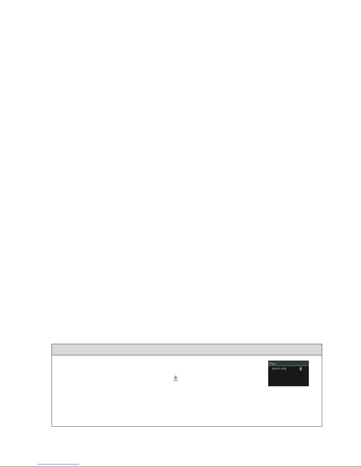
----------------------- General: System Configuration & Control -----------------------
Ultra 4K Tool Box User Guide, v1,2
B-17
Figure B-9:
‘Files’ area from
which MIB file may
be downloaded
Figure B-8: SNMP Section of the System page of the Configuration window,
showing the details that need to be filled in.
B.5.2 Programming the SNMP Manager
SNMP Managers essentially operate by issuing Get and Set commands to Object IDs (OIDs).
Specifying the operations that are carried out e.g. in response to an SNMP trap requires
knowledge of the OIDs that correspond to the system parameters that you want to affect.
The 4K Tool Box provides access to the details of the OIDs it uses, together with details of the
current value of any parameter and whether this parameter is Read/Write or Read Only but not in
human-readable form. The information needed to translate the OIDs into human-readable data is
detailed in a MIB file, a copy of which can be downloaded from the System page of the
Configuration window (as described in Section B.5.3).
The best way to discover about the OIDs used by the 4K Tool Box, their meanings and their
possible values is to load a copy of the MIB file into a ‘MIB Browser’ such as that provided by
iReasoning. (Even the ‘free’ version of their MIB Browser provides sufficient information for
you to readily determine the instructions you need to give to your SNMP Manager.)
Calling up the 4K Tool Box via its IP address from the MIB Browser gives access to a full list of
the OIDs it uses, which the MIB Browser is then able to interpret in terms of system parameters
and permitted values with the aid of the MIB file that has been loaded.
The result is that you can readily see from the MIB Browser the OID associated with any
parameter, the current setting of any parameter and the alternative values that can be set.
The MIB Browser will typically also be able to distinguish between parameters that are Read
Only and those that are Read/Write, and will offer you the option of changing the setting of
Read/Write parameters from within the MIB Browser.
B.5.3 Downloading the MIB file
A copy of the MIB file can be downloaded from the ‘Files’ area of the System page of the
Configuration window. The MIB file is downloaded as OmniTekUltra.mib
The steps to use are given below.
To download SNMP Command and Parameter IDs:
1. Display the Configuration window and use the System option on the
Button Bar to select the System page.
2. Download the MIB file by selecting the symbol next to SNMP MIB
in the Files area to the right of the System page.
The file is downloaded to the Downloads directory on the PC/handheld
from which the 4K Tool Box is being controlled, from where you can
transfer it to the required location.
Page 46

----------------------- General: System Configuration & Control -----------------------
Ultra 4K Tool Box User Guide, v1.2
B-18
Page 47

Ultra 4K Tool Box User Guide, v1.2
Section 2: Conversion Facilities
This section describes the facilities offered by the Ultra 4K Tool Box for modifying
the format of the input signal.
In the current version, these facilities include:
Switching the delivery format of the signal e.g. between SDI and HDMI
Switching the video standard
Page 48

----------------------------------- Conversion Facilities -----------------------------------
Ultra 4K Tool Box User Guide, v1.2
Page 49

Ultra 4K Tool Box User Guide, v1.2 D-1
D : Format Conversion
This section describes how to set up the Ultra 4K Tool Box to convert a video signal from one
delivery format and video standard to another.
D.1 Overview
The Ultra 4K Tool Box supports a wide range of video standards delivered over SDI, HDMI or
DisplayPort, both as input to and as output from the Tool Box. The precise details of the range
supported depends on the VIDEO_xx options that are installed (see Section A.1.3).
The 4K Tool Box allows video in any of the supported video standards delivered to any of its
input ports to be output in any of the supported video standards from any of its output ports.
Conversion between the two sets of delivery formats and video standards is an intrinsic
consequence of feeding in input using one delivery format & video standard and specifying a
different delivery format and/or video standard for the output.
Specifying the required conversion is therefore part and parcel of defining how the inputs and
outputs on the 4K Tool Box are to be used, and is carried out using the Connections window of
the 4K Tool Box (shown below).
The conversion is carried out within the Analyzer/Converter component of the 4K Tool Box.
Figure D-1: Connections Window display
The 4K Tool Box automatically detects the standard of each input connected to it, so all the user
has to do is:
Select the required input and define its route through the 4K Tool Box’s
Analyzer/Converter to the required output (as described in Section B.1)
Set the Output video standard as described below.
Page 50

-----------------------Conversion Facilities: Format Conversion ----------------------
Ultra 4K Tool Box User Guide, v1.2
D-2
D.2 Setting up the 4K Tool Box to carry out the Required Conversion
There are five steps to setting up the 4K Tool Box to carry out a particular format conversion:
1. Displaying the Connections window.
2. Linking the input port(s) you will be using to the Analyser/Converter block and sending
the output from that block to the required Output port(s).
3. Setting the required Output Video Standard.
4. Setting the required Genlock
5. Setting the smoothing/sharpening algorithm for use in any pixel re-sizing that is required.
All five steps are used as part of the basic procedure of configuring the 4K Tool Box described
in Section B. The following sections therefore just outline of the actions required, with pointers
to the parts of Section B where extra information can be found.
Step 1: Displaying the Connections Window
To display the Connections window:
Select the Connections tab at the top of the screen:
Step 2: Making the required connections
Connections need to be formed on the Connections window
(i) Between the input port you are going to use and the input to the Analyser/Converter
block in the central column of the screen display; and
(ii) Between the output from the Analyser/Converter block and the output port you are
going to use.
Cables also need to be plugged into the selected ports to achieve the required results.
Make the required connections as follows. For further information, see Section B.1.1.
To make the connection between the input and the Analyser/Converter block
1. Click on the little square on the right-hand side of the required input block in the left-hand
column of the display.
Note: The HDMI and DisplayPort inputs are not supported in the current version.
2. Drag to the corresponding square on the left-hand side of the Analyser/Converter block.
To make the connection between the Analyser/Converter block and the
output
1. Click on the little square on the right-hand side of the
Analyser/Converter block.
2. Drag to the corresponding square on the left-hand side of the required
output block in the right-hand column of the display.
Note: Where SDI Inputs and/or SDI Outputs are being used, you also need
to set up the list of SDI ports being used as described in Sections B.1.2 and
B.1.3.
Figure D-2:
Output options
Page 51
-----------------------Conversion Facilities: Format Conversion ----------------------
Ultra 4K Tool Box User Guide, v1.2
D-3
Step 3: Set the Output Video Standard
The Output Video Standard can either be selected from a list of current selections or it can be
picked it out via its properties of Interface, Raster size, refresh rate and Sampling type.
The steps to use are outlined below. For further information, see Section B.1.5.
To set the Output Video Standard to a recent selection:
1. Click on the down arrow to the right of the Output Video Standard currently being quoted
for the port. A drop-down list of recent selections is displayed.
2. Select the required standard from the list displayed.
To set the Output Video Standard via its properties:
1. Click on the symbol to the right of the current Output
Video Standard.
The dialogue shown to the right is displayed.
2. Starting with the Interface entry, click on the down arrow
to the right of the current selection and pick the required
option from the drop-down list that is displayed.
3. Use the same procedure to set the Raster setting, then the
Refresh then the Sampling.
4. When all entries have been set to define the required video
standard, click on the Set option at the bottom of the
dialogue to select this video standard and return to the
Connections window.
Step 4: Set the Required Genlock
The steps to use are outlined below. For further information, see Section B.1.6.
1. Select the required Genlock source:
Pick the required source from the drop-down menu offered in the Genlock area in the
bottom left-hand corner of the display.
2. To select between Genlock and Free Run:
Click on the down-arrow next to the current Genlock selection, and click the required option.
3. Set the timing:
Click on the symbol to the right of the current Genlock selection, and use the dialogue
that is displayed to set the required timing adjustment in Lines and Pixels.
Page 52

-----------------------Conversion Facilities: Format Conversion ----------------------
Ultra 4K Tool Box User Guide, v1.2
D-4
Step 5: Set the Required Smoothing/Sharpening Algorithm
The smoothing that is applied is controlled by the Filter setting, shown alongside the
Analyser/Converter.
The steps to use are outlined below. For further information, see Section B.1.7.
To set the interpolation algorithm that is applied:
Select the required algorithm from the drop-down menu of Filter settings.
Note: Selecting SMPTE Flat selects the algorithm adopted by SMPTE as its standard.
Page 53

Ultra 4K Tool Box User Guide, v1.2
Section 3: Signal Analysis
The Ultra 4K Tool Box’s Viewer window offers a wide choice of image analyses,
described over the next few sections of this User Guide.
Page 54

--------------------------------------- Signal Analysis ---------------------------------------
Ultra 4K Tool Box User Guide, v1.2
Page 55

Ultra 4K Tool Box User Guide, v1.2 H-1
H : The Viewer Window
H.1 Overview
The Viewer window is used to display the results of data analysis tools applied by the Ultra 4K
Tool Box to the currently selected input(s). The different analyses may be shown either
individually or as a quad split.
Figure H-1: Sample View Window display
The range of analyses that may be viewed depends on the options purchased but may include:
Pixel data
Gamut charts
Status information
Eye and Jitter diagrams
Reference Timing measurements
This section looks at the overall features of the Viewer window. The displays associated with the
different analysis tools that may be applied are described in a separate sections.
Definitions
The main part of the Viewer window is divided into ‘Tiles’, each showing a particular aspect of
the video under test. The displays that can appear on the Viewer window’s Tiles are referred to
as ‘Views’. Each View comprises the results from one analysis tool and may include pictures,
meters, traces, etc.
Selecting the Viewer Window
To display the Viewer window:
Select the Viewer tab at the top of the screen:
Page 56

---------------------------- Signal Analysis: Viewer Window -----------------------------
Ultra 4K Tool Box User Guide, v1.2
H-2
H.1.1 Screen Layout
The main section of the Viewer window comprises four Tiles, arranged in the simple ‘quad split’
shown below. This allows the results from up to four different monitoring tools to be displayed
simultaneously.
Alongside the Tiles is a panel used to display the current settings and to provide access to the
various menus that are available to call on.
Figure H-2: Basic Quad-Split of Tiles
The Tiles are referred to in terms of the View they show. So the screen shown above comprises
an Eye Waveform tile, a Gamut Meters tile, a Status tile (showing Video data) and a Zoom View
tile.
The View displayed on any Tile can readily be replaced by a different View or another version
of the Status display. (There is generally no point in displaying a second version of a View that is
already displayed as the copies will be configured in the same way and always show the same
information.) The steps to use are given in Section H.2.1.
It is also possible to select any Tile and show the View it contains full screen. (These actions are
described in Section H.2.2.)
Different combinations of Tiles may be saved for re-use on a subsequent occasion by recording
these as Presets. (How this is down is described in Section B.3.)
A ‘Title Bar’ is shown at the top of each tile, detailing the View that is displayed, while the
Button Bar associated with the View is shown at the bottom of the screen. These are described in
more detail below.
To the right of the main display is a panel offering settings etc. relevant to the current View(s).
Note: If a tile isn’t big enough to show the entire display, the tile will be shown with scroll bars.
These scroll bars can be simply dragged to show the part of the display you are interested in.
Page 57

---------------------------- Signal Analysis: Viewer Window -----------------------------
Ultra 4K Tool Box User Guide, v1.2
H-3
Title Bar
Each Tile is topped with a Title Bar that gives brief details of the View it is displaying and the
input it relates to. Also included on this line are a down-arrow (used in selecting different Views
to display) and a symbol used in making the screen display full-size.
Figure H-3: Example Title Bar
Button Bar
Associated with each View is a Button Bar that generally offers access to up to eight commonlyrequired actions or settings but can offer more, particularly on those displays that display data
from the multiple ‘Inputs’ used by some of the more complex video formats. Options are
selected from the Button Bar by clicking on the required option.
Figure H-4: Example Button Bar
H.2 Viewer Window Operations
This section describes some general actions that are carried out on the Viewer window.
Selecting the Views to display
Switching between Full screen and Multiple tile display
Configuring Individual Views
H.2.1 View Selection
Any tile can readily be replaced by one showing another View. You will generally want to select
a View that isn’t currently displayed in any of the tiles or a second copy of the Status View
(which offers a choice of displays). There is generally no point in displaying a second version of
a View that is already displayed as the copies will be configured in the same way and always
show the same information.
To display the required View:
1. Click on the down-arrow in the Title Bar of the tile that you want to replace.
2. Select the required View from the menu that is displayed.
The View that is currently displayed is replaced by the View you select.
H.2.2 Switching between Full Screen and Multiple Tile displays
Views can be displayed full screen (and subsequently switched back to a multi-tile display).
Furthermore, Views displayed full screen can either be shown complete with Title Bar and
Button Bar or, in the case of the Picture View, further expanded to fill the whole screen (i.e.
without either the Title Bar or the Button Bar.
While Views are being displayed full screen (complete with Title Bar and Button Bar), the other
Views from the multi-tile version of the display can be displayed full screen by scrolling the
display right or left.
In general, two techniques may be used to switch between the different forms of the display as follows:
Clicking on the / icon at the right-hand end of the Title Bar of the required tile.
Pressing the ESC key on an attached keyboard
Page 58

---------------------------- Signal Analysis: Viewer Window -----------------------------
Ultra 4K Tool Box User Guide, v1.2
H-4
For most tiles, these operations simply toggle the display between the Quad-Split arrangement of
the tiles and the full screen display.
For the Picture View, the pattern is extended to include the full screen display without a Title
Bar and a special procedure is needed to return from this state to the Multiple Tile version of the
display. The required steps are illustrated in the following diagrams.
Figure H-5: General steps Multi-Tile ↔ Full Screen
Figure H-6: Steps Multi-Tile ↔ Full Screen for Picture View
Page 59

---------------------------- Signal Analysis: Viewer Window -----------------------------
Ultra 4K Tool Box User Guide, v1.2
H-5
H.2.3 Configuring a View
Depending on which View is selected, there may be different options as to how that View is
displayed. For instance, the display may offer a choice of colouring schemes for the different
traces. Alternatively, you may be offered a choice of number formats in which to express data.
These options may be offered in two ways:
Through the Button Bar associated with the View
Through an area dedicated to the selected View, shown in the panel on the right-hand
side of the screen.
The Button Bar typically comprises a set of short-cuts to the most common actions or settings
associated with the selected View. Some of the Button Bar options directly switch controls on
and off: other Button Bar options cycle through the possible settings.
The panel area typically includes options to select the range of parameters for which results are
displayed or the colour(s) in which traces are shown.
To set any property of a tile:
1. First check the options in the Button Bar.
2. If the Button Bar includes the required action/setting, click on the relevant option.
Otherwise make the required setting in the right-hand panel.
H.3 Focus of Analysis
While displays such as the Gamut Meters (described in Section N) and the
Status (described in Section O) take their data from entire frames of video,
displays such as the Data View (described in Section J) and the Data
Waveform (described in Section L) just show results from a section of a
particular line while the Zoom View (described in Section K) just shows
the pixels around a particular point in the current image.
The focus of the analysis for displays such as the Data View, Data
Waveform and the Zoom View is either a particular pixel or a particular
data sample, the location of which is detailed by the two cursor roses
shown in the bottom right-hand corner of the Viewer window display. The
way in which this focus is shown depends on the View that is being
displayed.
The ‘SMPTE Sample’ cursor rose is concerned with identifying the position in terms of pixels
(X) and lines (Y) of the currently selected sample within the data stream– or in the case of video
formats delivered as a number of subimages, its position within the data stream identified by the
Input specified in the bottom right-hand corner of the display.
The ‘Active Picture’ cursor rose gives the position of the equivalent pixel in terms of pixels (X)
and lines (Y) away from the top left-hand corner of the Active Picture part of the video frame
(unless this position is in the blanking, in which case X and Y are given as ---- to indicate that
the current sample isn’t part of the Active Picture).
The sample/pixel position on which the analysis is focussed can be changed in several ways
(outlined below). The appropriate method(s) at any point depend both on the result you wish to
achieve and the type of View you are currently working in. The method(s) appropriate to any
particular View are detailed in the section of this Guide that describes that View.
Page 60
---------------------------- Signal Analysis: Viewer Window -----------------------------
Ultra 4K Tool Box User Guide, v1.2
H-6
Moving the Focus with the Mouse:
Clicking on a pixel within an image, or on the part of a display showing pixel data, moves
the cursor to the selected pixel.
In the Picture View (see Section K), it is also possible to display a cursor which can then be
dragged to a different position.
Moving the Focus using the Cursor Roses:
Clicking on one of the arrow symbols of either the Active Picture cursor rose or the SMPTE
Sample cursor rose moves the focus in the direction indicated by the arrow.
Editing the X, Y values shown in either cursor rose moves the focus to the sample/pixel
position corresponding to the new values.
Note: As you make these changes, the values shown in the other cursor rose change to show the
corresponding location. The complexity of the way in pixel data is delivered across the various
video standards means that it is not always easy to follow how the X,Y values shown in the
SMPTE Sample cursor rose relate to those shown in the Active Picture cursor rose. In general, it
is best to simply to work with the cursor rose appropriate to the type of examination you are
currently carrying out, and to keep a note of the details of any cursor position that you want to
return to (including the Input that is currently selected), because apparently just moving a few
steps in one direction and then back again can leave you in a very different position to where you
started if you fail to notice a change in the selected Input. Further details are given in the
appropriate sections of this Guide.
H.4 Saving and Recalling Specific Tile Selections
The Views currently selected for display in the tiles and how these Views are configured can be
saved for re-use by recording this set-up as a ‘View Preset’.
A View Preset records:
The View shown on each tile and which input is being analysed
How each View is configured (as recorded in the Properties control)
The following gives the steps used to record the current selection of Views as a View Preset.
These steps can also be used to update the configuration recorded as a particular Preset.
To save the current Viewer or Config window set-up as a Preset:
1. Click and hold on the number under which you want to record the
Preset. Note: The details of any Preset previously assigned to this
Preset number will be overwritten.
2. A dialogue similar to the one shown here will appear:
3. Set a suitable description as the Name for the Preset, then select OK.
The purpose of this name is to aid identification. It will be shown on briefly at the top of the
display when the mouse pointer hovers over the Preset e.g. before the Preset is selected.
To select a Preset by Number:
1. Display the window in which you want to use the chosen Preset.
2. Click on the number of the required Preset in the Preset Toolbar.
For more detailed instructions and further information about using presets, see Section B.3.
Page 61

Ultra 4K Tool Box User Guide, v1.2 J-1
J : Pixel Data
This section describes the different ways the Ultra 4K Tool Box offers for examining the data on
the input signal(s) providing the video that is being analysed.
The displays offered are:
(i) Data View (Section J.2)
Displays the values for a selected set of pixels delivered over the different ‘Inputs’ that
contribute to the final image. (These ‘Inputs’ don’t correspond to cables but instead to
what SMPTE describe as ‘Virtual Interfaces’. While several SDI cables may be needed
to deliver one image, each of those cables may be delivering more than one Input.)
When the video being analysed is delivered over a single Input, the screen just shows
the pixel data for that Input. For video such as HD (1.5Gb/s) Dual-link and ‘Square
Division’ 4K UHD, however, the image is delivered over two or more Inputs: in these
cases, the Data Viewer displays a separate set of pixel data for each Input.
(ii) Cable View (Section J.3)
Where video is delivered over multiple Inputs, these Inputs are generally delivered over
more than one cable with each cable delivering one or more Input. Where two or more
Inputs are delivered on a single cable, these are delivered interleaved.
The Cable View displays the data delivered by each cable. Colouring is used to identify
data from the different Inputs and show how this has been interleaved.
(iii) Ancillary Data Viewer (Section J.4)
Displays a decode of any ANC packets detected at the current cursor position.
In each case, the focus for the display is linked to the current X,Y positions indicated by the
Active Picture and SMPTE Sample cursor roses shown on the Viewer window towards the
bottom of the right-hand panel. It is also linked to the position of the crosshair cursor that is
optionally displayed on the Picture View (see Section K.3) and to the pixel/pixels highlighted on
the Zoom View (see Section K.5).
The focus of the display can be moved using the cursor roses as described in Section H.3. It can
also be moved by clicking both within the Data View and Cable View displays described in this
section and within the Picture View and Zoom View displays described in Section K. It should
be noted, however, that while movements made on the Picture View and the Zoom View are
restricted to the Active part of each frame, those on the Data View and Cable View can be used
to explore the blanking.
The different displays are described below. First, however, a brief look at the different ways in
which the focus for these displays can be moved on a pixel-by-pixel level.
Note: Interpreting the data shown in these displays is not straightforward when it is associated
with video formats such as ‘Square Division’ or ‘2-Sample Interleave’ 4K UHD as these draw
their data from more than one input. When working with such standards, you are strongly
recommended to have a copy of the relevant SMPTE standard to hand to refer to.
Page 62
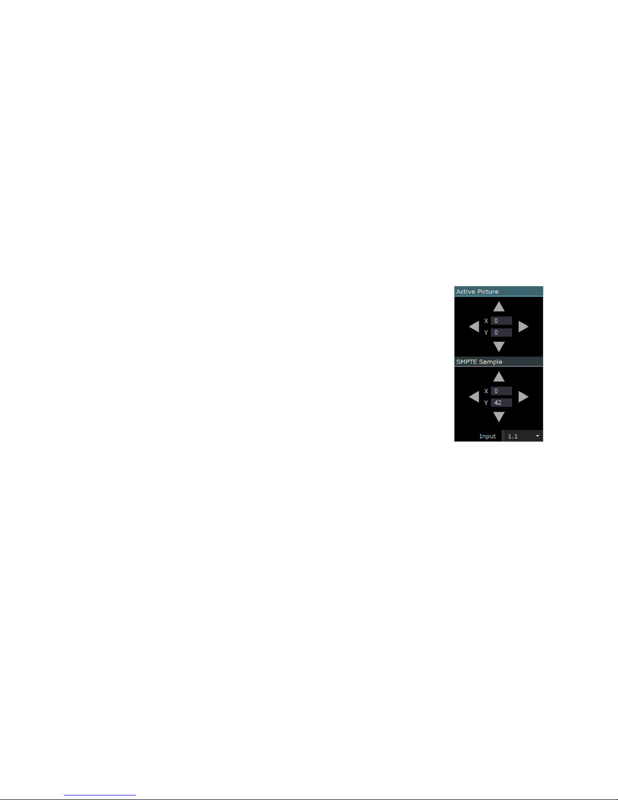
-------------------------------- Signal Analysis: Pixel Data --------------------------------
J-2 Ultra 4K Tool Box User Guide, v1.2
J.1 The Focus of the Display and its Movement Pixel-by-Pixel
In general terms, the section of the image about which data is displayed is set by the current
position of the ‘Active Picture cursor’ which also sets the position of the crosshair that can be
shown on the Picture display (see Section K.3).
Where video is delivered by a single Input, there is a very simple relationship between the position of
this cursor and the samples displayed by the Data View and the Cable View. The only complication
is that the Active Picture cursor is constrained to be within the Active area of the image, whereas the
Data View can shows data both from the Active area and from the surrounding Blanking area.
Where video is delivered over multiple Inputs, the connection between pixels and data-stream
samples is more complex because the data contributing to an individual pixel within the final
image can be drawn from pixels delivered by different Inputs that may be at different locations
in terms of numbers of lines and numbers of samples from the start of the frame.
To cater for this, the Ultra 4K Tool Box maintains two cursors: an ‘Active Picture’ cursor that
navigates around the Active image area; and a ‘SMPTE Sample’ cursor that navigates across
lines and sample positions within an Input.
The current locations of these two cursors are shown within Active Picture
and SMPTE Sample cursor roses shown in the right-hand panel of the
Viewer window. Additionally, their respective cursors can be moved rightleft & up-down by clicking on the arrows around the compass rose.
Alternatively the cursor can be moved to a specified position by typing the
X, Y coordinates of the required position in the centre of the rose.
At any one time, you work with one of the two cursors: the cursor that is
currently selected is indicated by highlighting its title bar.
However, the relationship between the two cursors is automatically
maintained by the 4K Tool Box, so moving the Active Picture cursor
switches the SMPTE Sample cursor to the corresponding position. Similarly
moving the SMPTE Sample cursor moves the Active Picture cursor to the
corresponding position.
The resulting movement is not always easy to follow:
1. Where video is delivered in 4:2:2 or 4:2:0 format, data from a single
sample may be used across more than one image pixel.
2. Where video is delivered over more than one input, the Active
Picture cursor position can relate to different SMPTE Sample positions on the different
inputs.
The way in which the first issue is resolved is by making either the Active Picture cursor or the
SMPTE Sample cursor the currently selected cursor and using outlining to identify the
pixel(s)/sample(s) that relate to this selection.
The second issue is resolved by nominating one of the Inputs as the one through which the two
cursor positions correlate.
Figure J-1:
The Active Picture
and SMPTE Sample
Cursor Roses
Page 63
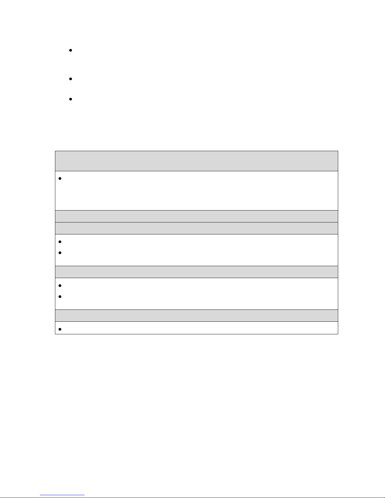
-------------------------------- Signal Analysis: Pixel Data --------------------------------
Ultra 4K Tool Box User Guide, v1.2 J-3
The rules then become:
When the Active Picture cursor is moved, the SMPTE Sample cursor changes to select
the line and sample number of the sample in the nominated Input that provides the
luma value to the pixel picked out by the Active Picture cursor.
When the SMPTE Sample cursor is moved, the Active Picture cursor moves to the pixel
to which the selected sample on the nominated Input contributes its luma value.
When the SMPTE Sample cursor is moved into the Blanking area, the Active Picture
cursor is left on the edge of the Active area of the current display, with its X,Y position
shown as ---,---. It becomes active again when the cursor is moved back into the Active
Picture area.
The steps used to select the Input that acts as the link between the two cursors and to move the
cursors are given below.
To set the Input providing the link between the Active Picture and
SMPTE Sample cursors:
Pick the required Input from the drop-down list associated with the ‘Input’ entry shown at the
bottom of the SMPTE Sample cursor rose.
Note: Inputs are identified by n:m numbers where n is the number of the cable and m is the
number of the Input within that cable.
To move the cursor using the Cursor Roses:
To move the Active Picture cursor:
Either: Position the cursor by clicking on the arrows of the Active Picture cursor rose.
Or: Set the X, Y settings in the centre of the Active Picture cursor rose to the required line
and pixel values.
To move the SMPTE Sample cursor:
Either: Position the cursor by clicking on the arrows of the SMPTE Sample cursor rose.
Or: Set the X, Y settings in the centre of the SMPTE Sample cursor rose to the required line
and pixel values.
Where the required position is visible within a Data View, Cable View, Picture or Zoom View:
Simply click on the appropriate display at the required position.
Note: The sequence of SMPTE sample numbers as the cursor moves from left to right depends
on the video standard that is selected. In particular, Sample 0 isn’t necessarily at the left-hand
edge of line but is often half-way along the line.
Page 64

-------------------------------- Signal Analysis: Pixel Data --------------------------------
J-4 Ultra 4K Tool Box User Guide, v1.2
J.2 Data View
The Data View is one of the views that can be called up on the Viewer window.
It comprises a pixel-by-pixel display of the data in the Input/Inputs contributing to the image for
a number of pixels either side of the pixel selected by the SMPTE Sample Cursor.
Figure J-2: Example Data View display
The display comprises one or more horizontal sets of 10- or 12-bit data arranged in a block, showing
the data interpreted either in decimal or in hex. The top line of the block details the line of the
Input(s) from which the samples are taken, while the second line identifies the samples for which
data is displayed. The remaining lines of the block display the data associated with the samples.
The way in which the data should be interpreted is dependent on the part of the frame that is
being shown (Active Picture or Blanking).Within the Active Picture area, the data corresponds to
YUV values with Y shown on one line and U/V shown on the other line. (Whether the U/V value
shown should be interpreted as U or V is shown by the coloured bar at the bottom of the column
which is blue for U values and red for V values.. In other parts of the frame, the data displayed
can reflect a range of different data.
To help identification, the values are shown against different background colours as follows:
Green indicates pixel is within Active video
Blue indicates pixel is within a TRS packet
Purple indicates pixel is within an ANC packet
Light grey indicates pixel is within horizontal blanking
Black indicates pixel is within vertical blanking for field 1
Dark grey indicates pixel is within vertical blanking for field 2
Red indicates a data range error (i.e. video data outside the range specified on
the Video page of the Configuration window).
The Button Bar at the bottom of the display offers:
A quick route to SAV
A quick route to EAV
A Format option that setting principally selects between displaying the data in
hexadecimal, decimal but further offers the option of interpreting 10bit data as
8 bits + 2 bits. This has the advantage of making standard groupings such as those
associated with SAV and EAV easier to pick out.
Page 65

-------------------------------- Signal Analysis: Pixel Data --------------------------------
Ultra 4K Tool Box User Guide, v1.2 J-5
For video standards such as SD that deliver their data via a single Input, a single set of Y and
U/V data is displayed. For video standards such as 3G Level B 2-Sample Interleave 2160p that
take their data from multiple Inputs, multiple sets of data are shown – all showing the same
range of pixels.
The allocation of data to the different lines of the display follows the mappings for the different
video standards detailed in the relevant SMPTE standards:
SMPTE 372 for 1.5Gb/s Dual-Link video
SMPTE ST 425-1 for sub-1080-line 3G Level B Dual-Link and Level B Dual-Stream video
SMPTE ST 425-3 for 1080/2160-line 3G video
SMPTE ST 2081 for 6G video
The lines of the block are numbered using an n:m format where n identifies the cable on which
the Input is being delivered and m identifies the ‘Virtual Interface’ on that cable (in the
terminology of the SMPTE standards) corresponding to the Interface. The role in the final image
played by each Input is indicated by the bar shown to the right of the n:m number which is
coloured according to the colouring scheme used in the appropriate SMPTE standard.
An alternative ‘Cable-centric’ view is available in which the data is arranged in line with how it
is delivered by individual cables, again coloured in accordance with the colour scheme used in
the appropriate SMPTE standard. This is described in Section J.3.
The current cursor position is indicated by copper-coloured boxes around the relevant data. When the
SMPTE Sample cursor is selected, a single box is shown on each horizontal block, picking out the
selected sample. When the Active Picture cursor is selected, one or more smaller boxes may be
shown, picking out the different sample elements that contribute to the currently selected pixel. The
arrangement of smaller boxes shown is strongly dependent on the video standard of the signal that is
being analysed, in particular whether the Sampling is 4:4:4, 4:2:2 or 4:2:0.
Figure J-2: Example Data View displays (i) when the SMPTE Sample cursor is selected;
(ii) when the Active Picture cursor is selected
The current cursor position is maintained across the different displays and the different cursor
selections so that the user can follow the contributions being made from different bit periods to
any pixel. However, for a detailed analysis, you are strongly recommended to refer to the above
SMPTE standards (and to the other SMPTE standards that these documents refer to).
Page 66

-------------------------------- Signal Analysis: Pixel Data --------------------------------
J-6 Ultra 4K Tool Box User Guide, v1.2
To display the Data View:
1. Show the Viewer window.
2. Click on the down-arrow in the Title Bar of the tile that you want to replace.
3. Select Data Viewer from the menu that is displayed.
To go to the Start (SAV) or the End (EAV) of the Active Video :
Click the button on the Button Bar marked with the required location.
To see the data associated with other parts of the current image :
Use the techniques described in Section J.1 to move to the required position.
Note: It may be possible to pick out ANC packets embedded in the Horizontal Blanking from
these views but the easier option is to use the Ancillary Data Viewer described in Section J.4 to
display a text interpretation of the ANC packet.
J.2.1 Configuration
The 10-bit data shown in the Data View can be displayed either:
As decimal values;
As hex values; or
Split into an 8-bit value and a two-bit, both expressed in hex
The last of these options is useful in making standard groupings such as those associated with
SAV and EAV easier to pick out.
The different formats are offered through a Format button included on the Button Bar when the
Data View is selected.
To set the data format:
Click the Format button on the Button Bar until the required data format is selected.
Clicking this option cycles through the three possible settings.
J.3 Cable View
The 4K Tool Box’s Cable View is another of the views that can be called up on the Viewer
window.
It is similar to the Data View described in Section J.2.The principal difference is that, instead of
dividing the data into the different subimages that contribute to the final image, the Cable View
shows this data divided into lines according to the different cables on which it is delivered.
Examples of the Cable View display are shown below.
Figure J-3: Example ‘Cable View’ display (i) when the SMPTE Sample cursor is selected;
(ii) when the Active Picture cursor is selected
Page 67

-------------------------------- Signal Analysis: Pixel Data --------------------------------
Ultra 4K Tool Box User Guide, v1.2 J-7
The properties of the Cable View are essentially the same as those of the Data Viewer described
above. The Cable View also offers the same choices on its Button Bar as are offered by the Data
Viewer.
To display the Cable View:
1. Show the Viewer window.
2. Click on the down-arrow in the Title Bar of the tile that you want to replace.
3. Select Cable Viewer from the menu that is displayed.
To go to the Start (SAV) or the End (EAV) of the Active Video :
Click the button on the Button Bar marked with the required location.
To see the data associated with other parts of the current image :
Use the techniques described in Section J.1 to move to the required position.
To set the data format:
Click the Format button on the Button Bar until the required data format is selected.
Clicking this option cycles through the three possible settings
J.4 Ancillary Data Viewer
The Ancillary Data Viewer is another of the views that can be called up on the Viewer window,
and it can be used in conjunction with the Data View and Cable View displays to provide the
interpretation of ANC packets included within the video being analysed.
When the SMPTE Sample cursor is on an ANC packet in any of the contributory Inputs, the
Ancillary Data Viewer window will show the information it is able to extract from this packet.
A example of the Ancillary Data Viewer display is shown below.
Figure J-5: Example Ancillary Data Viewer display.
Page 68

-------------------------------- Signal Analysis: Pixel Data --------------------------------
J-8 Ultra 4K Tool Box User Guide, v1.2
ANC packets are included within the blanking and occupy either the Y stream (i.e. the part of the
Input stream used in the Active image area for luma data) or the C stream (i.e. the part of the Input
stream used in the Active image area for chroma data). The Ancillary DataViewer can therefore be
configured to just to display ANC packets detected in the Y stream or to display packets detected
in the C stream or both as required.
To display the Ancillary Data Viewer:
1. Show the Viewer window.
2. Click on the down-arrow in the Title Bar of the tile that you want to replace.
3. Select Ancillary Data Viewer from the menu that is displayed.
To set the Input from which data is shown:
Click the required Input on the Button Bar. The selected Input will become highlighted.
To display ANC Packets from the Y/C streams:
1. Click on the Ancillary Data Viewer to make it the active window.
2. Either: Highlight the required stream options on the Button Bar by
clicking on them.
Or: Set the Y stream and C stream options offered in the right-hand
panel to On (1) or Off (0) as required.
Note: The ability of the 4K Tool Box to interpret an ANC packet depends on whether the
appropriate ‘descriptor’ for this packet is installed. At the time of writing, XML format
descriptor files are supplied with the 4K Tool Box that allow it to interpret the following types of
ANC packet:
SMPTE 352 video standard packets
SMPTE RP 188 time code packets
SMPTE 2016 bar data packets
CEA-608 & CEA-708 closed caption and OP-47 teletext packets
EDH definition packets
AES-EBU and HDTV audio definition packets
Page 69

Ultra 4K Tool Box User Guide, v1.2 K-1
K : Picture View
K.1 Overview
The Ultra 4K Tool Box’s Picture View display provides a real-time, full resolution image of the
video input currently being processed by the 4K Tool Box’s Analyser.
Figure K-1: Example Picture Display.
Optional additions to this display include:
A crosshair cursor indicating the current focus for displays such as the Data View
(described in Section J) and the Data Waveform (described in Section L).
Up to two sets of outlines representing Safe Action and Safe Title cages.
The aspect ratio used for the display can either be set in line with a couple of standard screen
formats (16:9 and 4:3) or taken from Active Format Description data embedded in the video.
The Picture View is one of the displays that can be called up in the Viewer window of the
4K Tool Box’s User Interface, however web-based versions of the User Interface (such as that shown
where a PC or a handheld is used as the Control device) are not able to support full-resolution
images. At the time of writing, the full-resolution images can only be displayed where a ‘Local’ copy
of the User Interface is displayed on a suitable monitor plugged into the HDMI Output port. Other
displays of the User Interface just show a message advising the need for the display to be output on
an HDMI monitor.
Care is therefore needed in the set-up of the 4K Tool Box in order to display these images.
The following sections describe:
The required set-up (Section K.2.1)
How to call up the Picture View (Section K.2.2)
Showing (and hiding) the crosshair cursor (Section K.3)
Adding Safe Action/Safe Title Cages (Section K.4)
Also described is the Zoom View that can be shown of 15x15pixel or 31x31-pixel sections of the
display around the current position of the crosshair cursor.
Page 70

-------------------------- Signal Analysis: Picture View -----------------------------------
Ultra 4K Tool Box User Guide, v1.2
K-2
K.2 Displaying Picture Images
The following sections describe:
The set-up that is required to display Picture images
How to call up the Picture View display
The display options that are available
K.2.1 System Setup
To display the Picture images, you need:
1. Plug a suitable monitor into the HDMI output port on the rear panel of the 4K Tool Box.
HDMI Output Port
Figure K-2: Port into which monitor needs to be plugged
2. Use the Connections window to direct the output from the Analyser/Converter block into the
Local User Interface, and to direct the Local User Interface to the HDMI output port.
Figure K-3: Connections needed on the Connections window to display Full-Resolution Images
The steps needed to achieve the required result are therefore as follows:
To display Pictures on an HDMI monitor:
1. Plug a suitable HDMI monitor into the HDMI Output port on the 4K Tool Box.
2. Display the Connections window.
3. Make a link from the Analyser/Converter to the lower of the two little squares on the
right-hand-side of the Local User Interface.
4. Make a link from the upper square on the Local User Interface to the HDMI Output.
Note: It is not possible to take output from the 4K Tool Box’s Converter at the same time as
Picture images are displayed on the HDMI Monitor.
Page 71
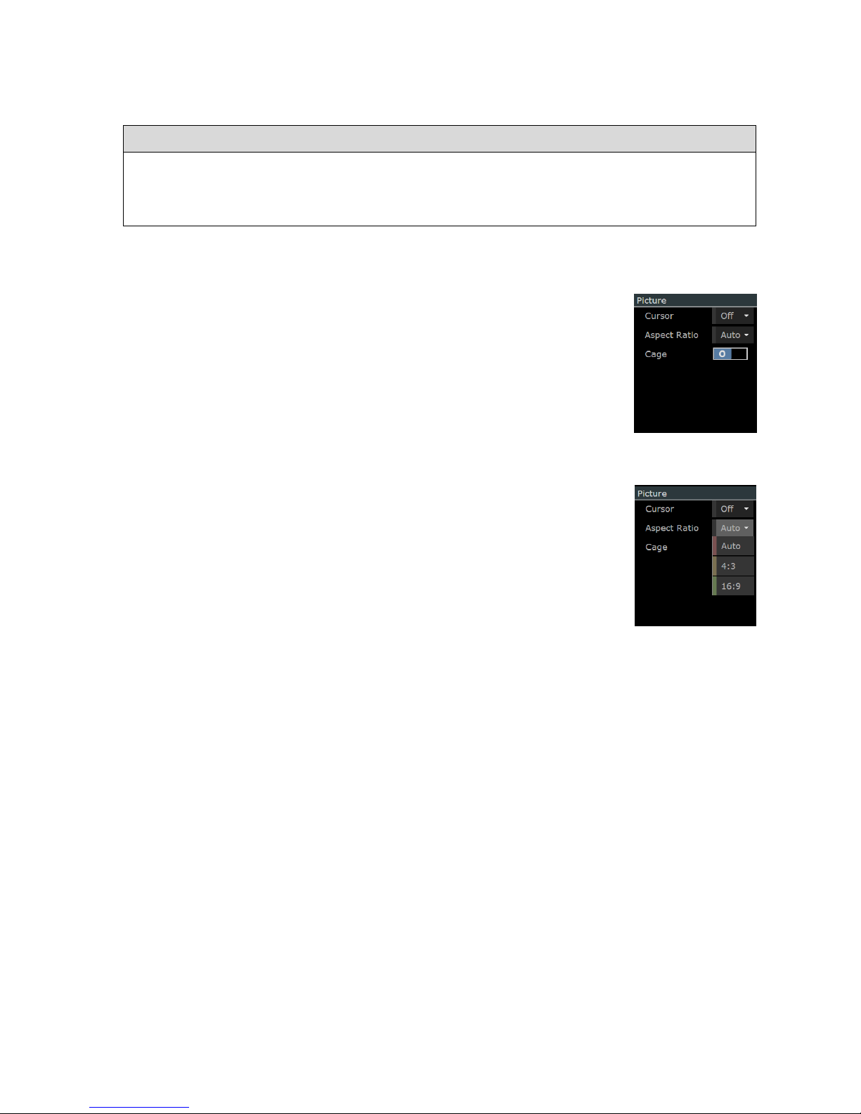
-------------------------- Signal Analysis: Picture View -----------------------------------
Ultra 4K Tool Box User Guide, v1.2
K-3
K.2.2 Picture View Selection
The Picture View is displayed on the User Interface as follows:
To display the Picture View:
1. Show the Viewer window.
2. Click on the down-arrow in the Title Bar of the tile that you want to replace.
3. Select Picture from the menu that is displayed.
K.2.3 Display Options
A range of display options are offered under the heading ‘Picture’ in the
right-hand panel of the Viewer window when the Picture View is selected.
Cursor
The Cursor option controls the display of a crosshair cursor indicating the
position within the Picture View of the current focus for displays such as
the Data View, the Data Waveform and the Zoom View.
The different ways in which this cursor can be moved are detailed in
Section K.3
Aspect Ratio
The aspect ratio of the image displayed within the Picture View can be set
from a range offered by the drop-down menu associated with the Aspect
Ratio entry. Note: The Auto option is not available in the current version
but in future versions will set the aspect ratio based on the Active Format
Description embedded in the selected input.
Cage
The Cage On/Off option controls the display of Safe Action and Safe Title
cages (see Section K.4).
K.3 Cursor
The focus for displays such as the Data View (described in Section J), the Zoom View (described
in Section K.5) and the Data Waveform (described in Section L) can be both shown and moved
on the Picture display.
This focus is optionally represented on the Picture View by a crosshair cursor, the position of
which is principally identified by the X, Y settings shown in the middle of the Active Picture
cursor rose displayed towards the bottom of the right-hand panel of the Viewer window.
The X, Y settings give the position of the cursor in pixels and lines relative to the top left-hand
corner of the Active Picture.
Display of the crosshair cursor is controlled by the Cursor option offered under the heading
‘Picture’ in the right-hand panel of the Viewer window. The On(1)/Off(0) setting of this option
controls whether the crosshair cursor is displayed or hidden.
Figure K-4:
Picture Properties.
Figure K-5:
Supported Aspect
Ratios
Page 72

-------------------------- Signal Analysis: Picture View -----------------------------------
Ultra 4K Tool Box User Guide, v1.2
K-4
A range of techniques can be used to move this cursor, including:
Use of the Active Picture cursor rose
Use of the SMPTE Sample cursor rose
(The way in which the SMPTE Sample cursor rose is linked to the Active Picture cursor
rose is explained in Section J which describes the various ways the 4K Tool Box offers
for displaying pixel data.)
Standard mouse-pointer click and drag techniques.
To show the crosshair cursor on the Picture View:
Set the Cursor option offered in the right-hand panel under Picture to On (1).
To hide the cursor, set the Cursor option to Off (0).
To position the crosshair cursor:
Either. Click the required position on the Picture View.
Or. Drag the crosshair cursor to the required position.
Or: Click on the arrow symbols of either the Active Picture cursor rose or the SMPTE
Sample cursor rose.
Or: Edit the X, Y values shown in either the Active Picture cursor rose or the SMPTE
Sample cursor rose.
Note: The way in which the X, Y values displayed by the SMPTE Sample cursor rose relate to
the X, Y position given for the cursor on the Active Picture cursor rose depends on the format of
the video that is being processed. For further information, see Section J.
K.4 Safe Action / Safe Title Cages
The 4K Tool Box allows ‘cages’ representing safe-action and safe-title areas to be marked out on
the Picture View.
Figure K-6: Picture View showing cages.
Page 73

-------------------------- Signal Analysis: Picture View -----------------------------------
Ultra 4K Tool Box User Guide, v1.2
K-5
Two sets of cages can be defined, allowing you to readily judge the positioning of any action and
any titles on a choice of screen geometries. For example, by setting up one set of cages for a 16:9
screen display and the other for a 4:3 screen display you will be able to simultaneously assess the
positioning of any action and any titles on these two screen formats.
Overall control over the display of the cages is given by the Cage option within the Picture
section of the right-hand panel which allows the display of cages to be turned On or Off at will.
The dimensions and positioning of the two Safe action and the two Safe title cages are
individually defined on the Video page of the Configuration window. The four cages are also
individually enabled, allowing you to select precisely which cages are displayed.
For both types of cage, you are offered a choice of using for a standard cage definition or a
‘Variable’ one.
The standard cage options select the cage dimensions defined for different screen sizes by
four major Standards authorities: SMPTE, the EBU, the ITU and ARIB
The ‘Variable’ cage options allow you to specify the dimensions you require. Opting for
a ‘Variable’ safe title cage also allows you to choose where this cage is positioned.
Both types of cage can be marked out using either a solid line or a dashed line. This can be used
to distinguish either between Safe Action and Safe Title cages or between the two sets of Safe
Action and Safe Title cages. This selection is also made on the Video page of the Configuration
window.
K.4.1 Set-Up
The cages are defined on the Video page of the Configuration window, which includes a Cages
section, shown in ‘closed-up’ form below.
Figure K-7: Cage section of Video Page of Configuration window.
The principal elements of this display are as follows:
Default fixed sizes
This setting is used to select the Standards body to follow in
setting cage dimensions that conform to published standards.
Note: The selection made here affects the definitions used for the
two Safe Title cages and two Safe Action cages when one of the
standard sizes is selected.
Safe title-1
Definition used for one of the two Safe Title cages. This definition
includes the option to omit this cage and to show the cage using a
dashed line rather than a solid line.
Safe-action-1
Similar definition used for one of the two Safe Action cages.
Safe title-2 and Safe action-2
Similar definitions for the other Safe Title and Safe Action cages.
Page 74

-------------------------- Signal Analysis: Picture View -----------------------------------
Ultra 4K Tool Box User Guide, v1.2
K-6
The procedure to follow in setting up the cages is as follows:
To set-up Cages:
Carry out the following steps for each of the Cages you want to set up.
To specify a ‘Standard’ Cage:
Note: These cages are always positioned centrally about the middle of the screen. Cages that are
displaced from this central position can only be implemented as Variable cages (see below).
1. Display the Video page of the Configuration
window.
2. Select the appropriate Standards body from the
drop-down menu offered on the Default fixed
sizes line of the Cages area of the display.
3. Select the required screen geometry from the dropdown menu offered on the first line of the Cage
definition.
Note: The Auto option is not available in the
current version but in future versions will show a
cage based on the Active Format Description
embedded in the selected input.
4. With the full Cage definition fully displayed,
move the Dashed setting to On (1) or Off (0) as
required. When Dashed is set to Off (0), the cage
will be displayed as a solid line.
To specify a ‘Variable’ Cage:
1. Display the Video page of the Configuration window.
2. Select Variable from the drop-down menu offered on the first line of the Cage definition.
3. With the full Cage definition fully displayed, set the values you require for the H and V
Sizes and for the H and V Offsets.
The values shown are quoted in terms of
percentages of the width/height of the screen. The
offsets are quoted from the middle of the screen
and refer to the position of the middle of the cage.
H Size and V Size can take values in the range 10 –
100, while H Offset and V Offset can take values in
the range –50 to 50 (though it should be noted that
if ±H Offset is greater than (100 – H Size)/2 or
±V Offset is greater than (100 – V Size)/2, part of
the cage will be off the edge of the screen.
4. Move the Dashed setting to On (1) or Off (0) as
required. When Dashed is set to Off (0), the cage
will be displayed as a solid line.
Page 75

-------------------------- Signal Analysis: Picture View -----------------------------------
Ultra 4K Tool Box User Guide, v1.2
K-7
To set up cages that enable comparison between results in two different screen formats:
The following steps allow comparison using the standard cages for two different sizes defined by
one of the supported Standards bodies.
Note: Comparisons across different Standards bodies or involving standards not supported by the
4K Tool Box require at least one set of cages to be set up as ‘Variable’ cages.
1. Display the Video page of the Configuration window.
2. Select the appropriate Standards body from the
drop-down menu offered on the Default fixed
sizes line of the Cages area of the display.
3. Set Safe title-1 and Safe action-1 to one of the
screen geometries that you want to compare.
4. Set Safe title-2 and Safe action-2 to the other
screen geometry.
5. Set the Dashed setting for each cage to On (1) or Off (0) as required to distinguish the two
sets of cages. For example, you might opt to set Dashed to Off(0) for Safe title-1 and Safe
action-1 and to On (1) for Safe title-2 and Safe action-2. Alternatively, you might opt to set
Dashed to On (1) for Safe title-1 and Safe title-2 but Off (0) for Safe action-1 and Safe
action-2 to allow you to readily distinguish between Safe title and Safe action cages.
To disable (and re-enable) individual cages:
Note: The values associated with your current selection are maintained across this procedure. In
particular, any Variable definition that you have set up for this cage will be restored when you
select Variable again.
Set any cage that is not required to Off on the Video page of the Configuration window.
To re-enable the cage, set the cage to the required standard or Variable as required.
K.4.2 Displaying the cages
Once the required cages have been defined (as described above), setting the Cage option within
the Picture properties to On (1) displays the cages that have been defined on the Picture view.
Note: Setting this Cage option to On (1) displays whatever cages are currently set to something
other than Off on the Video page of the Configuration window and uses the definitions given
on that page. Setting this Cage option to Off (0) clears the Picture display of all cages. To
change the combination of cages that are displayed, you need to switch the individual cages to
On or Off on the Video Configuration page.
Page 76
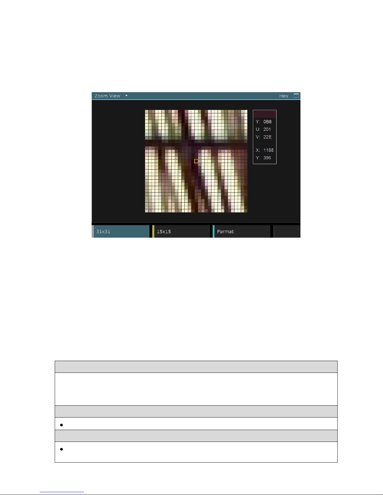
-------------------------- Signal Analysis: Picture View -----------------------------------
Ultra 4K Tool Box User Guide, v1.2
K-8
K.5 Zoom View
It is possible to zoom in for closer examination of the frame that is currently being displayed.
A scaled-up image is available for display as the Zoom View.
The Zoom View is included in the range of Views offered on the Viewer window, and the
display shown is illustrated below. The part of the frame that is shown is the area around the
current cursor position (as shown e.g. by the cursor on the Picture View (see page K-3).
Figure K-8: Example Zoom View.
Two versions of the Zoom View are offered: one showing 31x31 pixels and a more magnified
view that shows just 15x15 pixels. The above image shows the 31x31-pixel version of the
display. Options switching between these two versions are included on the Button Bar at the
bottom of the display.
Also included in the display is a set of details about the pixel currently under the mouse pointer
(where this is over the zoomed image) or if the mouse pointer isn’t on the zoomed image, about the
pixel at the current cursor position. The data shown comprises the Y, U and V values of the selected
pixel (in the currently selected format) and its X, Y position relative to the top left-hand corner of the
Active Picture (also picked out for the current cursor position on the Active Picture cursor rose).
The pixel data on the different data streams that contribute to these pixels can be seen by calling
up the Data View (described in Section J.2). This data can also be studied by calling up the Data
Waveform (described in Section L).
To display the Zoom View:
1. Show the Viewer window.
2. Click on the down-arrow in the Title Bar of the tile that you want to replace.
3. Select Zoom Viewer from the menu that is displayed.
To switch between 31x31-pixel display and the 15x15 pixel display:
Click the required button on the Zoom View Button Bar (illustrated above).
To switch how the Y, U and V values are expressed:
Click the Format button on the Zoom View Button Bar to cycle through the options
(identical to those offered by the Data Viewer and Cable Viewer).
Page 77
Ultra 4K Tool Box User Guide, v1.2 L-1
L : Waveform Display
This section describes the Data Waveform display offered by the Ultra 4K Tool Box. This is one of
the views that can be called up on the Viewer window, and it gives a graphical display of the YUV
values of the pixels shown on the central line of the Zoom View (described in Section K.5).
The display is offered in two forms, referred to as ‘Single’ and ‘Double’, The ‘Single’ version of
the waveform corresponds to the 15x15 version of the Zoom View and shows the data from
15 pixels. The ‘Double’ version of the waveform corresponds to the 31x31 version of the
Zoom View and shows data from 31 pixels. Examples of the two versions of the display are
shown below. The format in which the YUV data is displayed is selectable via the Format
option, with the current selection shown in the Title bar.
Figure L-1: Example ‘Single’ and ‘Double’ versions of the Data Waveform display.
In common with the various Pixel Data displays described in Section J, the focus for the display
is linked to the current X,Y positions indicated by the Active Picture and SMPTE Sample cursor
roses shown on the Viewer window towards the bottom of the right-hand panel. It is also linked
to the position of the crosshair cursor that is optionally displayed on the Picture View (see
Section K.3) and to the pixel highlighted on the Zoom View (see Section K.5).
The focus of the display can therefore be moved using the cursor roses as described in
Section H.3. It can also be moved by clicking within the Data Waveform, or within the Data
View and Cable View displays described in Section J or within the Picture View and Zoom
View displays described in Section K.
In common with the Picture View and Zoom View displays, the Data Waveform just shows data
from the Active area of the image. If the cursor position is moved into the Blanking area (e.g.
while working on the Data View display), the Data Waveform will remain showing data from
the edge of the Active area until such time as the cursor moves back into the Active area.
To display the Data Waveform:
1. Show the Viewer window.
2. Click on the down-arrow in the Title Bar of the tile that you want to replace.
3. Select Data Waveform from the menu that is displayed.
To set the scope of the display to 15 or 31 pixels :
Click the appropriate button on the Button Bar: Single for 15 pixels; Double for 31 pixels.
To see the data associated with other parts of the current image :
Use the techniques described in Sections H.3 and J.1 to move to the required position.
Page 78

--------------------------- Signal Analysis: Waveform Display ---------------------------
L-2 Ultra 4K Tool Box User Guide, v1.2
Page 79
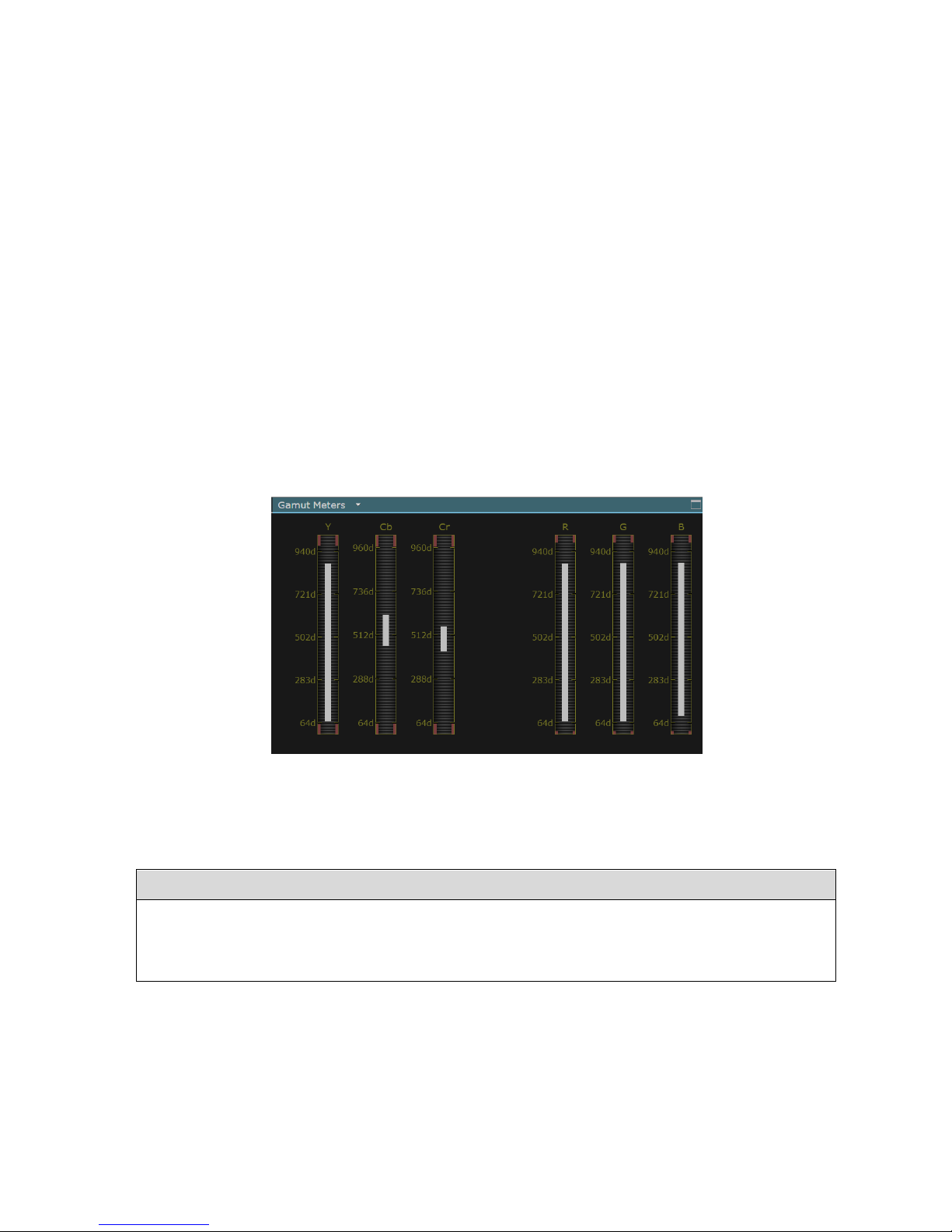
Ultra 4K Tool Box User Guide, v1.2 N-1
N : Gamut Analysis
The Ultra 4K Tool Box currently offers two ways of monitoring the gamut of the colour
components within the video being analysed.
One option is offered by the Status display (described in Section O) which among other things
reports the current value of both YCbCr and RGB colour components and reports when these go
outside the permitted range set on the Video page of the Configuration window.
The other option is offered by the Gamut Meters display described in this section.
N.1 Gamut Meters
The Gamut Meters display is one of the ‘Views’ that can be shown on the Viewer window.
It comprises a set of bar graphs, each showing the range of values for one of the different colour
components in the video currently being analysed. (The display is configurable to show just the
colour components that you are interested in.)
An example of the Gamut Meters display is shown below.
Figure N-1: Example Gamut Meters display.
The individual graphs show the ranges encompassed by the current frame. Where the values go
outside the range of acceptable values, the values in excess are shown in red.
To display the Gamut Meters display:
1. Show the Viewer window.
2. Click on the down-arrow in the Tile Title of the tile that you want to replace.
3. Select Gamut Meters from the menu that is displayed.
Page 80

---------------------------- Signal Analysis: Gamut Analysis -----------------------------
Ultra 4K Tool Box User Guide, v1.2
N-2
N.1.1 Setting the Permitted Ranges
The permitted ranges of the different colour components are part of overall Video configuration, set
on the Video page of the Configuration window (see Section B.2.1). The Ultra 4K Tool Box is
delivered with the various maximum and minimum values set in accordance with standard practice
within the industry but the user is free to set their own choice of values.
Separate settings are made for the YCbCr and RGB colour spaces. The section of the Video page
where these settings are made is shown below:
Figure N-2: Gamut Range section of Video page of Configuration window.
The display is divided into separate sections covering YCbCr and RGB colour spaces.
The YCbCr section allows you to set separate maximum and minimum values for the luma and the
chroma elements. The RGB section sets a single range of permitted values to apply across all three
colour components. The values are all expressed as decimal values.
The first line of each group is used to specify the percentage of the image which needs to be out of
range before an error is reported.
N.1.2 Selecting the Colour Components to be Displayed
The range of colour components for which bar graphs are displayed is
controlled through On(1)/Off(0) selectors shown in the right-hand
panel when the Gamut Meters view is selected.
Figure N-3: Selection of the Gamut Meters shown.
Page 81

Ultra 4K Tool Box User Guide, v1.2 O-1
O : Status
Real time status information about the video signal that is currently being analysed may be
displayed by calling up the Status View. Aspects of the signal where errors have occurred are
highlighted in the displays to draw your attention to these.
O.1 The Status View
The Status View offered by the Ultra 4K Tool box is one of the displays that can be called up on
the Viewer window.
It comprises a collection of ‘pages’ covering different aspects of the video that is currently being
analysed. The aspects of the video covered by the different pages of the display include:
Overall parameters such as Video Format and Gamut Range
Parameters relating to the individual ‘Inputs’ contributing to the final image
Eye and Jitter data
An example page from the display is shown below.
Figure O-1: Example page from the Status View
The Status View is one of the displays that may be called up on the Viewer window.
The pages of the display are each associated with a particular button on the Button Bar. In some
cases, just one page is called up by pressing the associated button but the various ‘Input n:m’
buttons in the right-hand half of the Button Bar each cycle through a set of pages about the
specified Input.
The information that is offered is readily seen by calling up the different pages of the Status
display. Detailed information about the data displayed is given in Section O.2.
As shown in the example display, the values associated with the individual status items are
normally shown in white text but can be coloured red. Red is used to make it immediately clear
where the value currently being reported is incorrect in some way.
In several cases, the information shown includes a count of the number of errors that have
occurred since the time these counts were last restarted. A Reset option is included on the Button
Bar that can be used at any time to restart the counting by returning all these counts to zero
(see Section O.1.3).
Page 82

---------------------------------- Signal Analysis: Status -----------------------------------
Ultra 4K Tool Box User Guide, v1.2
O-2
O.1.1 Selection
The Status View is displayed as follows.
Note: If required, more than one copy of the Status View may be displayed, set to show different
pages from the display.
To display the Status View:
1. Show the Viewer window.
2. Click on the down-arrow in the Title Bar of the tile that you want to replace.
3. Select Status from the menu that is displayed.
To select the page of information that is displayed:
1. Click the appropriate button on the Button Bar.
2. Where necessary, click the button again to cycle through the set of displays accessed via the
selected button.
O.1.2 Error Ranges, Persistence and Severity
The level at which any aspect of the video becomes in error, the length of time that this condition
has to persist for an error to be reported and the severity of that error (Error/Warning/OK) is
part of the system configuration. The Ultra 4K Tool Box is delivered with these levels set in
accordance with standard practice within the industry. The current settings can be viewed and
adjusted as required on the Video page of the Configuration window.
Further details are given where this page of the Configuration window is described (Section B.2.1).
O.1.3 Resetting Error Counts
The second number given for some of parameters displayed in the Status View represents the
number of errors that have been detected since the error counter was last reset.
These counts can be reset to zero as follows:
To reset all of the error counts to zero:
Select the Reset option from the Button Bar
Note: Error counts are also automatically reset following a loss of signal.
O.2 Video Information Displayed
This section provides background information on the video parameters that appear in the various
status displays. The page of the Status View on which each parameter appears is shown in
brackets.
Note: The levels at which an error is deemed to have occurred and the length of time the error
condition has to persist before an error is reported are set on the Video page of the
Configuration window as described in Section B.2.1.
Page 83

---------------------------------- Signal Analysis: S
tatus -----------------------------------
Ultra 4K Tool Box User Guide, v1.2
O-3
Format (All pages)
A Format entry is given at the top of each page of the Status View. On pages relating to Inputs,
it gives the standard to which the individual input is locked - automatically determined by the 4K
Tool Box e.g. from SMPTE 352 packets within the video stream. For pages such as the Video
and Physical pages, it gives the video standard of the signal produced by combining the various
different inputs.
Gamut Errors (Video page)
The Video page of the Status display shows errors associated with YCbCr and RGB data. (The
range of acceptable values is set on the Video page of the Configuration window.)
The YCbCr section of this display gives the number of pixels for which the YCbCr data is in
error as a percentage of the current frame, the total number of frames for which the error level
recorded on the Video page of the Configuration window was exceeded since the last reset and a
count of these error frames per second (EFPS). It also shows the maximum and minimum
Y, Cb and Cr values experienced.
The RGB Range section gives the number of pixels for which the YCbCr data would be invalid
if converted to RGB space as a percentage of the current frame, the total number of frames for
which the error level recorded in the Video page of the Configuration window was exceeded
since the last reset and a count of these error frames per second (EFPS). It also shows the
maximum and minimum RGB values experienced.
TRS etc. Errors (Input n:m: Page 1 of 3 )
The entries in this section show parameters in error and give error counts for a range of standard
features of the video data stream. For instance, the ANC entry counts invalid ANC checksums.
The Line entry counts TRS packets where the line number specified does not agree with the line
number calculated internally. Note: This entry is only applicable to HD and 3G video: Line
numbers are not included in TRS packets in SD.
To check CRC/EDH values, the 4K Tool Box calculates a new ‘CRC’ value from the incoming
data, and compares this value with the CRC (EDH) value embedded in the data. If there is a
difference, this is flagged as an error. The CRC values that have been calculated for the active
area and for each full field/frame are also displayed. This data may be used to assess the degree
to which video data has been degraded by the path over which it has been transmitted.
Timecode Data (Input n:m: Page 2 of 3)
The 4K Tool Box checks the input stream for timecode data. Where a timecode is present, it is
displayed alongside the corresponding timecode type.
Note: ATC packets are timecode packets that can be loaded with either a LTC, VITC #1, or
VITC #2 timecode. These timecodes are completely independent so you may see different values
where one part of the display uses VITC #1 codes while another uses VITC #2.
SMPTE 352 Data (Input n:m: Page 3 of 3)
The Luma and Chroma entries interpret SMPTE 352 data (where detected).
Eye/Jitter Data (Physical page – where supported)
The entries in this section report:
The amount of Jitter (expressed in UI) for different filter settings.
The Eye amplitude (expressed in mV)
The Eye rise/fall times (expressed in ps)
The Eye Rise/Fall ‘Delta’ i.e. the difference between measured rise and fall times
(expressed in ps)
Page 84

---------------------------------- Signal Analysis: Status -----------------------------------
Ultra 4K Tool Box User Guide, v1.2
O-4
Page 85

Ultra 4K Tool Box User Guide, v1.2
Section 4: Physical Layer Analysis
This section describes the facilities the Ultra 4K Tool Box offers for examining
physical characteristics of the video signal such as signal amplitude, rise & fall
times, jitter and timing.
.
Page 86

--------------------------------- Physical Layer Analysis ---------------------------------
Ultra 4K Tool Box User Guide, v1.2
Page 87

Ultra 4K Tool Box User Guide, v1.2 S-1
S : Eye & Jitter Measurement
This section describes the tools available for assessing video integrity of SDI video transmissions
and for locating sources of jitter. To analyse any SDI video signal up to and including 6G-SDI,
the system you use will need to include the EYE option, together with any VIDEO_xx options
that are needed to support the video standards that you wish to analyse.
Figure S-1: Eye Waveform display
S.1 Overview
The various measurements and assessment discussed in this section result from analysis of the
carrier of an SDI video transmission.
The characteristics of this analogue signal are determined through time equivalent sampling.
After an initial set-up period in which the sampling builds up sufficient data, it becomes possible
to determine parameters such as the signal amplitude, the unit interval, the rise time and the fall
time of the signal, together with information about the level of jitter in the signal. It is also
possible to identify the waveband in which jitter occurs, which can help in identifying its source.
These are all parameters that affect the integrity of any transmission and ultimately whether the
receiver will be able to interpret the signal sufficiently accurately to display the desired images.
Most of them are also subject to limits imposed by transmission standards.
The analysis of the carrier signal is carried out by the 4K Tool Box’s integrated Eye Scan
facility, the input to which is a dedicated ‘Eye’ SDI port on the back of the instrument (see ‘SetUp below). The data gathered is used both to generate an Eye diagram & a set of Jitter ‘Meters’,
and to determine the basic signal amplitude, rise-time etc. parameters. Some of these parameters
are displayed alongside the Eye diagram & Jitter Meters: additional status information can be
found from the Status displays (see Section O).
Page 88

------------------------------- Physical Layer: Eye & Jitter --------------------------------
Ultra 4K Tool Box User Guide, v1.2
S-2
S.1.1 Facilities Offered
The following displays are offered:
1. Jitter Meters – a set of meters showing the jitter content that remains following the
application of a set of high-pass filters. The waveband in which the timing jitter is
occurring can be deduced by comparing the values shown by the different meters.
2. Eye Waveform giving a graphical representation of the signal which in turn gives a
physical representation of the different signal parameters (amplitude, unit interval, rise
time, fall time etc.). The Eye also allows a subjective assessment of transmission
integrity.
The same general steps are involved in working with these displays as are used with other Views
(see Section H). Further information is given on the Physical page of the Status View (see
Section O).
It is expected that the main displays to be used in monitoring performance will be the Physical
page of the Status View and the Eye Waveform. The Jitter Meters principally provide an aid to
engineers in tracking down sources of jitter with the aim of eliminating these.
S.1.2 Set-Up
The Ultra 4K Tool Box is automatically configured to direct any input to the ‘Eye’ SDI port on
the back panel to the built-in Eye Scan facility. The process of setting up the Tool Box to carry
out transport layer measurements is therefore one of.
1. Connecting the SDI signal to the ‘Eye’ port on the Ultra 4K Tool Box
2. Calling up the required displays.
The port into which the signal needs to be fed is picked out on the following diagram.
SDI Eye Input
Figure S-2: The dedicated Eye port on the Ultra 4K Tool Box
The steps needed to call up the required displays and options for configuring these displays are
described in the following sections.
Page 89

------------------------------- Physical Layer: Eye & Jitter --------------------------------
Ultra 4K Tool Box User Guide, v1.2
S-3
S.2 Jitter Meters
Figure S-3: Jitter Meters display
The Jitter Meters display comprises a set of ‘traffic light’-coloured meter scales, each including a
diamond-shaped solid marker that indicates (in a suitably dampened way) the effect of jitter in
the selected pass band on the position of the clock edges in the carrier signal that is being
analysed. Alongside each solid marker is an ‘open’ marker that shows the current instantaneous
jitter value.
The high pass filter that is applied in each case is detailed below the meter, along with the
measured peak-to-peak (P-P) value. Comparing the readings of the different meters allows you
to deduce the waveband(s) in which jitter energy is chiefly concentrated. Identifying these
wavebands often provides a clue to the source of the jitter.
Each meter is divided into a clear section (in which the markers are white), an amber section in
which the markers are yellow and a red section in which the markers are also red. A red marker
corresponds to a jitter level that is over the error level specified on the Video page of the
Configuration window. A yellow marker corresponds to a jitter level that is between 70% and
100% of the specified error level, while a White marker corresponds to a jitter level that is less
than 70% of the specified error level.
At any time, you can chose to add markers to the display that record the current Jitter values by
taking the Lock Markers option on the Button Bar. Blue outlines are then added at the current
position of the diamond markers, allowing you to compare subsequent Jitter levels against these
reference values. These Blue outlines can be shown or hidden as required by selecting the Show
Markers option from the Button Bar.
Note: The jitter values displayed are only valid once the 4K Tool Box has locked to the input.
While the 4K Tool Box is in the process of locking, the Jitter meters are greyed out.
Page 90
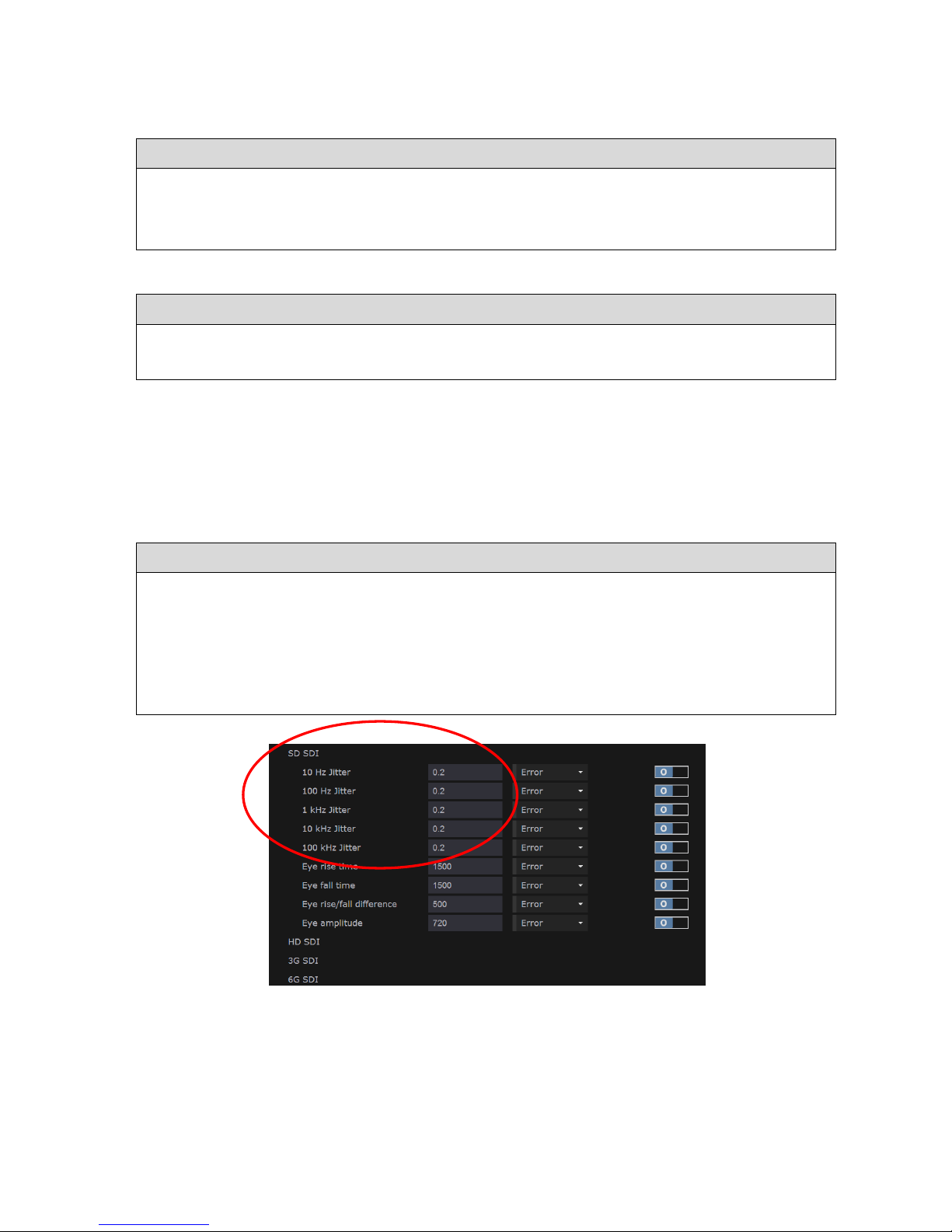
------------------------------- Physical Layer: Eye & Jitter --------------------------------
Ultra 4K Tool Box User Guide, v1.2
S-4
S.2.1 Selecting the Jitter Meters display
The Jitter Meters display is one of the views that can be called up on the Viewer window.
To display the Jitter Meters:
1. Show the Viewer window.
2. Click on the down-arrow in the Title Bar of the tile that you want to replace.
3. Select Jitter Meters from the menu that is displayed.
S.2.2 Recording the current Meter Positions
To mark the current positions of the Meters:
1. Select Lock Markers from the Button Bar.
2. Use the accompanying Show Markers option to show/hide these markers as required.
S.2.3 Setting the Meter Scale and Colour-Transition Points
The scale of each meter and the points at which the transitions are made between the different
colourings are all based on the value at which the amount of jitter is deemed to be in error.
This value is set on the Video page of the Configuration window (see Section B.2.1) and is set
individually for each video standard class (SD, HD, 3G etc.) and each High Pass Filter (10Hz,
100Hz, 1kHz, 10kHz, 100kHz).
To set the Meter Scale and the Colour Transition Points:
1. Show the Configuration window, and select the Video page of this window.
2. In the Error Checking section of the display, set in the first column of entries the number
of UI at which you want the jitter level to be deemed to be in error for each Video Standard
type (SD, HD etc.) and for each High Pass Filter (10Hz, 100Hz etc.).
The 4K Tool Box will base both the Meter Scale and the Colour Transition Points of each
Jitter Meter it displays on the values you set here
Figure S-4: Section of the Video page of the Configuration window that controls
the Jitter Meter display
The colour transitions and the end of the meter are then set as follows:
Amber – Red transition Value set on the Video page of the Configuration window
Clear – Amber transition 70% of above value
End of meter 170% of above value
Page 91

------------------------------- Physical Layer: Eye & Jitter --------------------------------
Ultra 4K Tool Box User Guide, v1.2
S-5
S.3 Eye Waveform
The Eye Waveform presents the data carrier signal in the way it might be displayed on an
oscilloscope, though produced in a very different manner. While the oscilloscope is able to work
directly with the data carrier signal, the Eye Waveform displayed on the Ultra 4K Tool Box is
built up through time equivalent sampling of this analogue signal.
Figure S-5: Example Eye Waveform display
There are a number of signal quality assessments that can be determined from an Eye Waveform.
The main ones are the signal amplitude (eye height) and rise and fall times, the results for which
are shown in the top right-hand corner of the display. The measurements made in order to deduce
these values are illustrated in the following diagram. (The “Rise/Fall low amplitude” level and
the “Rise/Fall high amplitude” level are defined as 20% and 80% of the signal amplitude.)
80%
20%
Signal
Amplitude
Fall TimeRise Time
Figure S-6: The principal Eye Waveform measurements
Page 92
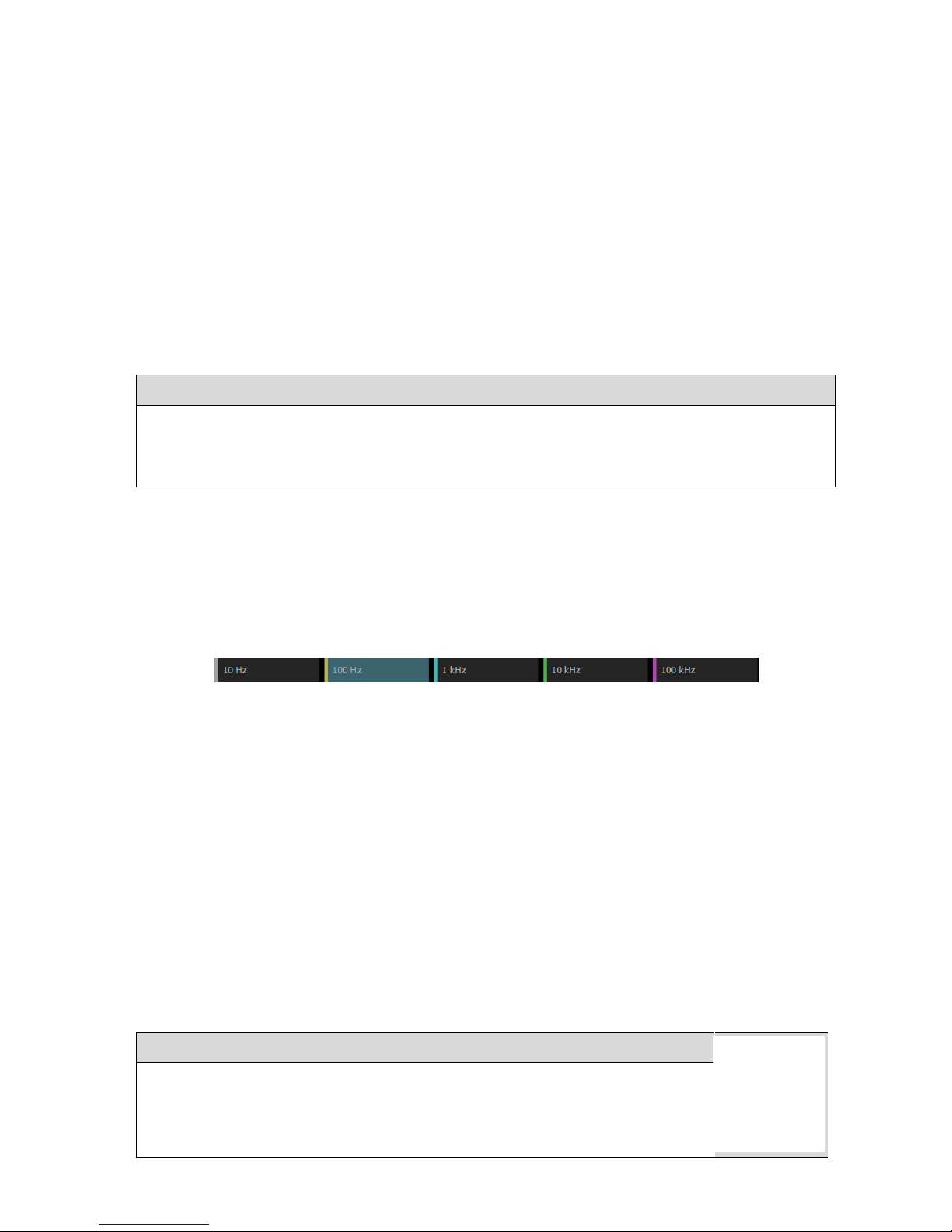
------------------------------- Physical Layer: Eye & Jitter --------------------------------
Ultra 4K Tool Box User Guide, v1.2
S-6
The Eye diagram shown also allows you to judge how well the signal is synchronized with the
signal clock, whether the signal suffers from overshoot or undershoot, and whether the signal is
likely to be correctly interpreted by the receiver. (This last judgment can be made from how open
the eye appears when compared against the eye diagrams associated with comparable
transmission that have or haven’t been correctly interpreted.)
Other features of the display include a Jitter meter showing the jitter in a selected pass band
(chosen on the Button Bar) and a histogram is also shown to the left of the Eye diagram. This
histogram indicates the relative amount of time spent at each signal level. The peaks in this
histogram are taken as marking the maximum and minimum signal levels.
S.3.1 Selecting the Eye Waveform display
The Eye Waveform display is one of the views that can be called up on the Viewer window.
To display the Eye Waveform:
1. Show the Viewer window.
2. Click on the down-arrow in the Title Bar of the tile that you want to replace.
3. Select Eye Waveform from the menu that is displayed.
S.3.2 Selecting the Jitter Meter that is displayed
Shown above the Eye diagram is one of the Jitter Meters from the Jitter Meters display.
The choice of which Jitter Meter is displayed is controlled from the Button Bar. When the Eye
Waveform view is selected, this shows buttons corresponding to the different high-pass filters
that are applied. To select a particular Jitter Meter, click the corresponding button.
Figure S-7: Eye Waveform Button Bar
S.3.3 Display Colouring
The proportion of the time the signal is spending at a particular level is indicated by the
histogram shown to the left of the Eye diagram. It is also indicated in the diagram itself through
either the colour used or the intensity of colour used, depending on the colouring scheme used to
display the Eye diagram.
The 4K Tool Box offers a choice of four colouring schemes: Cyan, Green, White and ‘Ramp’.
The selection is made through the Colour setting offered in the Eye Waveform area of the right-
hand panel shown when the Eye Waveform view is selected.
Cyan, Green and White each select versions of the display in which the proportion of the time
spent at each level is indicated by the intensity of the colouring. The Ramp setting selects the
colouring scheme used in Figure S-5 in which the colours of the rainbow from violet to red are
used to indicate the range of intensities from lowest to highest (with black used for zero).
To set the colouring scheme used:
1. Select the Eye Waveform display.
2. Click on the down-arrow shown in the right-hand panel alongside the
current Colour selection and select the required colouring scheme from the
menu that is displayed.
Page 93

------------------------------- Physical Layer: Eye & Jitter --------------------------------
Ultra 4K Tool Box User Guide, v1.2
S-7
S.3.4 Obtaining Signal Parameters from the Eye Waveform
The 4K Tool Box provides an automated read-out of signal amplitude, rise
time and fall time in the top right-hand corner of the display.
S.3.5 Transmission Integrity
A measure of whether the signal can be expected to be correctly interpreted at the receiver is
given by the degree to which the central ‘eye’ appears open.
In making this assessment, the user will typically judge the height and width of the eye at a
‘Decision point’ approximately half-way across the eye.
There are, however, no hard and fast measures that can be applied. Determining the
characteristics of the Eye diagram at the point at which reception stops being sufficiently error
free is a matter of experience.
Figure S-8:
Eye Parameters.
Page 94

------------------------------- Physical Layer: Eye & Jitter --------------------------------
Ultra 4K Tool Box User Guide, v1.2
S-8
Page 95

Ultra 4K Tool Box User Guide, v1.2 T-1
T : Timing Measurement
This section describes the timing measurements that can be made using the Ultra 4K Tool Box.
These measurements can be used to show both:
The difference in timing between the different inputs contributing to the video that is
currently being analysed; and
The difference in timing between each input and an external reference signal (where
supplied)
T.1 Overview
The different timing measurements are all made through the Timing display, which is one of the
‘Views’ that can be called up on the Viewer window.
An example of the Timing display is shown below.
Figure T-1: Example Timing display
This display comprises one or more ‘meters’, one for each input that is contributing to the video
that is currently being analysed.
Each meter shows the degree to which the input named below the meter is advanced or delayed
relative to the Reference signal named at the top of the display. For example, the meters shown
in the above example show the timing of a set of four SDI Inputs relative to the first of those
Inputs. The input that acts as the reference is selected using the Button Bar.
A diamond-shaped marker on each meter shows the measured timing. This timing is also
interpreted both in terms of Lines & Pixels and microseconds immediately below the meter (but
see ‘IMPORTANT’ below).
The measurements are made in terms of the time between the Start of Frame on the Input under
test and the next Start of Frame to occur on the selected Reference signal. These two events can
be no more than one frame apart and, as the actual ordering of the frames is unknown, the
measurement is interpreted as the Input under test either being up to 0.5 frames in advance of the
selected Reference or being up to 0.5 frames behind to the selected Reference i.e. any timing that
is over 0.5 frames in advance rolls round to become less than 0.5 frames behind (and vice versa).
Page 96

---------------------------------- Physical Layer: T
iming -----------------------------------
Ultra 4K Tool Box User Guide, v1.2
T-2
The meters are marked out in tenths of a frame, going between advanced by 0.5 frames on the
left and delayed by 0.5 frames on the right, with ‘0’ in the middle. The position of the marker
can therefore be interpreted as follows:
Marker at ‘0’: the Input under test is exactly synchronised with the Reference signal
Marker left of centre: the Input under test is ahead of the Reference signal
Marker right of centre: the Input under test is behind the Reference signal
These interpretations should be reinforced by the word ‘advanced’ or ‘delayed’ shown below
the meter after the number of microseconds.
To display the Timing display:
1. Show the Viewer window.
2. Click on the down-arrow in the Tile Title of the tile that you want to replace.
3. Select Timing from the menu that is displayed.
IMPORTANT: Timing differences between the constituent Inputs to the video that is currently
being analysed can be made without any additional set-up, while measurements against an
external reference signal just require a suitable Reference signal to be plugged into the
Composite port on the 4K Tool Box. If, however, you are intending the compare the 4K Tool
Box’s measurements against the measurements produced by another system, there may be other
settings to make in order to ensure that these measurements are completely compatible. There is
also the option of presenting the results using the ‘Line-Based’ format of some other T&M
systems. These additional actions are described in Section T.2 below.
T.2 Set-Up
While timing differences between constituent Inputs can be determined without any additional
set-up, additional actions may be needed:
(i) To measure timing against an external Reference signal
(ii) To produce data that can be compared against measurements on other measurement systems
T.2.1 Set-Up for Measurement Against an External Reference Signal
The signal used as the external Reference needs to meet the following three criteria:
1. It needs to be set up to deliver video of the same video standard as the Inputs under test.
2. The reference signal used may either be Analogue Black (0.3V p-p) or Tri-level (0.6V p-p).
3. It needs to be fed into the Composite port on the back panel of the 4K Tool Box.
Composite connecter
used for Reference signal
Figure T-2: Rear view of the Ultra 4K Tool Box showing the Composite connector
to be used where an external reference signal is required.
Page 97

---------------------------------- Physical Layer: T
iming -----------------------------------
Ultra 4K Tool Box User Guide, v1.2
T-3
T.2.2 Set-Up to give Line-Based Timings
How the Lines and Pixels values should be interpreted depends on the setting of the Line Based
timing option in the Timing section of the Video page of the Configuration window.
When this option is turned Off (0), the advance/delay is always the number of lines plus the number
of pixels. When Line-Based timing is turned On (1), however, the line count is given to the nearest
whole number of lines and the pixel count should either be added to the line count if the values are
both positive or both negative but subtracted from the line count if the signs are opposite.
Figure T-3: Timing section of the Video Configuration page.
T.3 Comparing the Timing of Constituent Inputs
Where video is delivered over two or more separate Inputs, the relative timing of these Inputs
can readily be assessed using the 4K Tool Box’s Timing display.
To obtain the relative timings, you simply need to select one of the constituent Inputs as the
Reference. The meters on the display then show the timing of the other Inputs relative to the
Input used as the Reference.
Figure T-4: Timing display configured to compare the timing of four constituent Inputs
To compare the timing of constituent Inputs:
1. Select the Timing display in a tile of the Viewer window.
2. Select one of the constituent Inputs as the Reference by clicking the appropriate button on
the Button Bar.
The timings shown in the display then show the values relative to the selected Input.
Page 98

---------------------------------- Physical Layer: Timing -----------------------------------
Ultra 4K Tool Box User Guide, v1.2
T-4
T.4 Comparing Timing against an External Reference
To compare the timing of any Input against an External Reference, you need to:
1. Feed a suitable reference signal into the Composite port on the 4K Tool Box.
2. Select Composite as the Reference for the Timing analysis.
Figure T-5: Timing display set up to compare against an External reference.
To compare timing against an External reference:
1. Feed a suitable reference signal into the Composite port on the 4K Tool Box
(see Section T.2.1 above).
2. Select the Timing display in a tile of the Viewer window.
3. Click on the Ref=Composite button on the Button Bar to select the external reference signal
as the Reference for the timings.
The timings shown in the display then show the values relative to the external reference
signal.
Page 99

Ultra 4K Tool Box User Guide, v1.2
Section 5: Generator
The Ultra 4K Tool Box includes a Generator for producing video output for test
purposes at any of the video standards supported by the Tool Box (i.e. all current
and anticipated 4K video formats up to 4096 x 2160/60p).
The video is generated from ‘Test Patterns’ which can be of various different
types:
Line Patterns;
Zone Plates;
Still Images; and
Combinations of these
The chapters in this section of the Ultra 4K Tool Box User Guide describe the
steps used to set up the required Test Patterns and play them out either singly or in
sequence. They also describe the various ways in which you can manipulate the
video prior to output, including introducing deliberate errors or inserting jitter for
test purposes.
Page 100

------------------------------------------ Generator ------------------------------------------
Ultra 4K Tool Box User Guide, v1.2
 Loading...