

Page 1
N
ext
USER’S MANUAL
GB
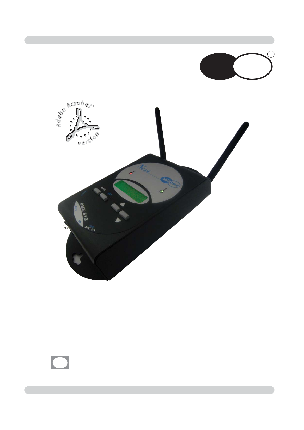
Wireless DMX 512 TRANSCEIVER
DMX
W
i
R
Page 2

Page 3

We congratulate you on your purchase of Wi DMX.
Before you proceed using this product, read this user’s manual carefully, as
it gives important information on safety, use and maintenance .
Page 4
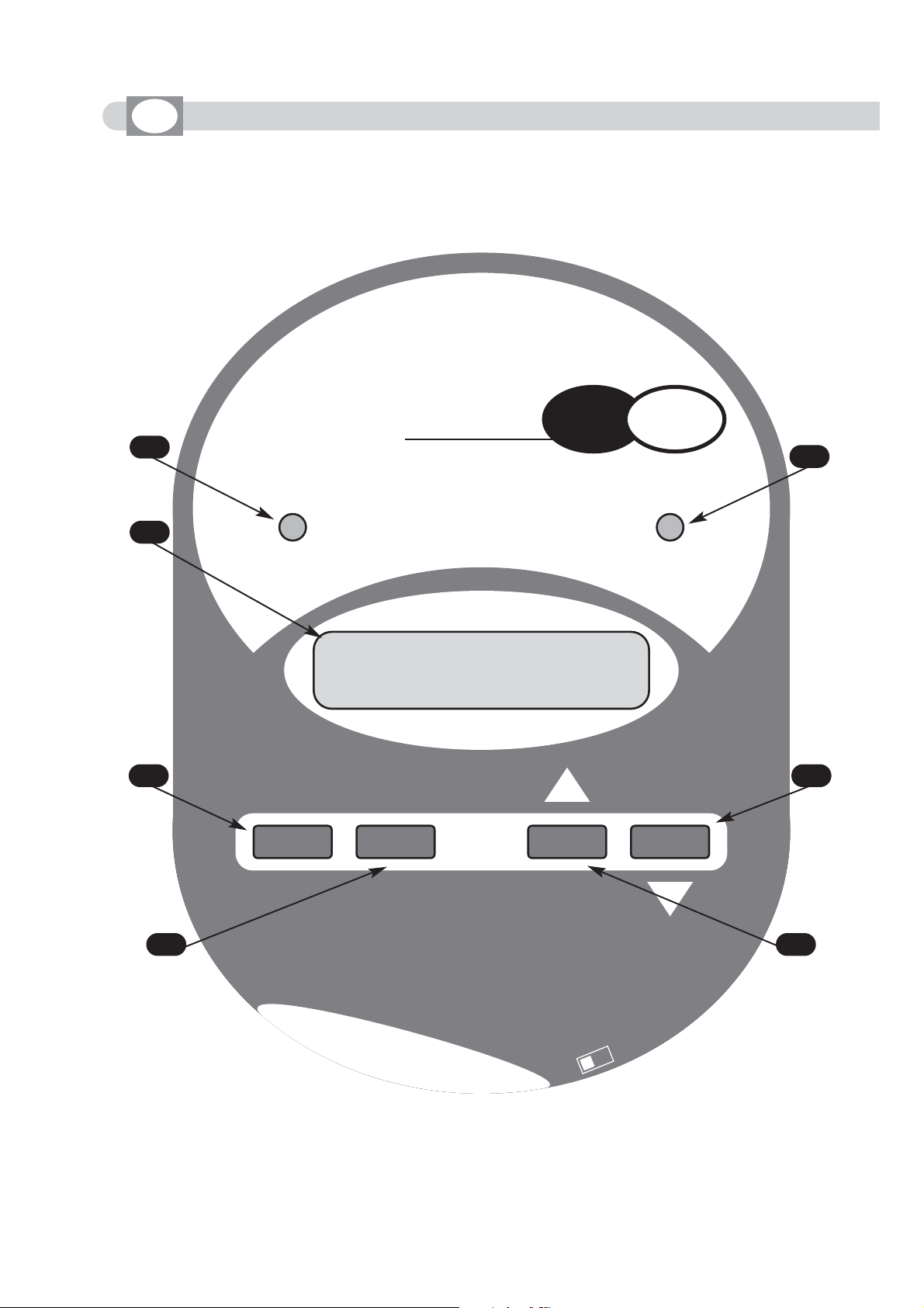
FRONT PANEL
GB
1
2
3
4
5
6
7
N
ext
12
W
DMX
i
DMX 512 ch 40hZ
MODE
SET
9V-DC IN
DMX 512
OUT
IN
TERM.
OFFON
Page 5

Shows the state of transmission/receipt of the channel 1
Shows the state of transmission/receipt of the channel 2
LCD display, it shows all the informations on the Wi DMX functions.
MODE key
SET key
DOWN key
UP key
1
2
3
4
5
6
7
Page 6

Setting of the equipment
1.1
Unpack WI DMX
1.2
Acessories and documentation provided with the equipment
Description of the side panel and installation
2.1
Description of the side panel
2.2 Making a DMX 512 signal cable
2.3
Input connection for power supply
2.4
Connection of the ac-adapter to main AC
Initial setting
3.1 Setting of the operating mode
Use of the equipment - operating modes
4.1
TRANSMITTER
mode
4.2 Setting of
Tx1
4.3
LED 1
function
4.4 Setting of
Tx2
4.5
LED 2
function
4.6 Receiver PAIRING
5.1
RECEIVER
mode
5.2 State of
Rx1
5.3
LED 1
function
5.4 State of
Rx2
5.5
LED 2
function
5.6 Pairing with Transmitter (GET PAIRING)
5.7 Pairing with Transmitter (GET PAIRING) using Wi D PEN
6.1
EXTENDER
mode
6.2 Setting of
Tx1
6.3
LED 1
function
6.4 Setting of
Rx2
6.5
LED 2
function
6.6 Receiver PAIRING
6.7 Pairing with Transmitter (GET PAIRING)
6.8 Pairing with Transmitter (GET PAIRING) using Wi D PEN
7.1 TX BACKUP mode
INDEX
Page 7
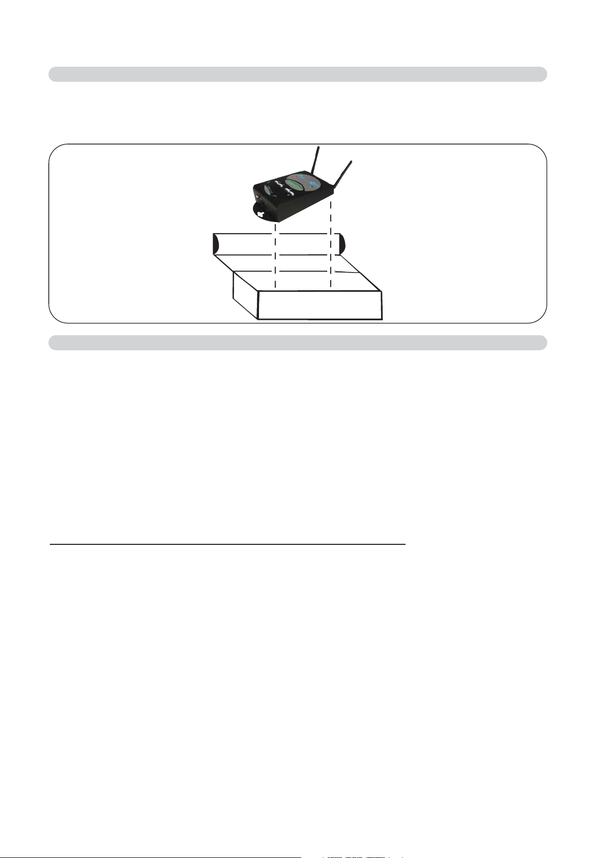
Open the box; Remove the ac-adapter and the documentation.
Take the equipment out of the box as shown in the picture below.
1.1 UNPACK WI-DMX
1.2
ACESSORIES AND DOCUMENTATION PROVIDED WITH THE EQUIPMENT
Verify the contents of the packing.
If one of the following parts of the packing is missing or damaged, please,
contact your dealer immediately.
• Wi DMX
• User’s manual.
• Warranty
• Ac-adapter mod.1814807
• 1 XLR 3/5 P male connector
• 1 XLR 3/5 P female connector
Read the following warnings before beginning installation.
• This unit is not intended for home use.
• Read this manual thoroughly and observe the following precautions before working
with the Wi DMX.
• Take care not to spill liquids on to the controller and do not use it in excessively humid
conditions.
• Do not install Wi DMX near heat sources or expose it to direct sunlight and do not
install in dusty environments without suitable protection.
• Do not use Wi DMX unless the ac-adapter cable and plug are in perfect condition
(replace or repair if necessary).
• Do not use solvents such as acetone or alcohol to clean the controller or the finish
and panel lettering will be damaged.
• If a fault occurs, consult your nearest service centre or a specialized light equipment
repair service. Do not attempt to repair the controller yourself.
Page 8
15
3
42
15
3
42
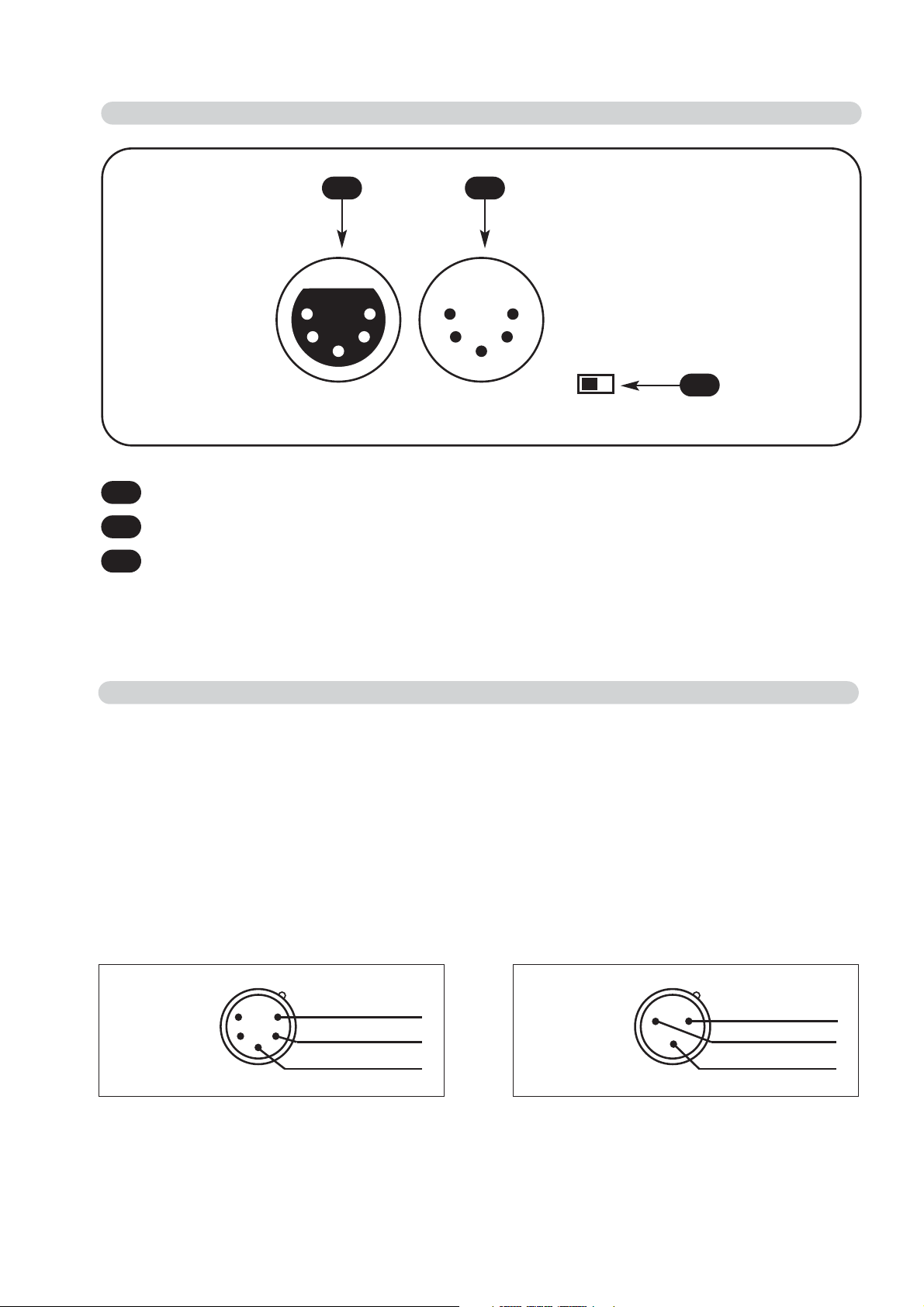
2.1 DESCRIPTION OF THE SIDE PANEL
1
Standard DMX 512 signal OUTPUT with a 3/5-pole cannon connector.
2
Standard DMX 512 signal INPUT with a 3/5-pole cannon connector.
3
DMX TERMINATOR
1 2
3
2.2
MAKING A DMX 512 SIGNAL CABLE
Wi DMX has a DMX 512 input/output that uses standard XLR 5-pin or XLR 3-pin
connectors.
The connection must be put into practice with shielded cable by these characteristics:
- 2 conductors + shield
- 120 Ohm impedance
- low capacity
- maximum transmission rate 250 Kbaud.
For the connection refer to the underlying picture
ATTENTION: the shield of the cable must never be connected to the ground of the
electrical system as this could cause faults during the working of the Wi DMX.
15
3
42
Common
DMX
-
DMX
+
XLR 5-pin
1
3
2
Common
DMX
-
DMX
+
XLR 3-pin
Page 9

2.3 INPUT CONNECTION FOR POWER SUPPLY
2.4 CONNECTION OF THE AC-ADAPTER TO THE MAIN AC
Plug the connector of the ac-adapter completly in the power input
To disconnect it, extract gently.
ATTENTION: do not use ac-adapters different from the one supplied, it
could cause serious damages at the internal circuitation.
4
MAKE SURE THAT VOLTAGE AND POWER FREQUENCY CORRESPOND TO
WHAT IS REPORTED ON THE AC ADAPTER PLATE.
The supplied ac-adapter has a plug, therefore you should only plug it in the
socket.
When Wi DMX is powered, on display
appears as in (Fig.1),if this condition is not
true, please check if there is power in the
electric socket or check the connection
between ac-adapter/controller and ac-adapter/electric socket.
If the problem persist, please consult your dealer.
4
WIRELESS
Fig. 1
N
ext
Page 10

SET
This procedure allows to change between
TRANSMITTER -
RECEIVER - EXTENDER - BACKUP
mode of operation
.
-Power down the Wi DMX.
-While holding down
SET key
(Fig.2),
Power up the Wi DMX.
REGARDLESS OF THE MODE, YOU MUST EXECUTE THE PAIRING OPERATIONS
EXPLAINED IN THE RELATIVE CHAPTERS OF THIS MANUAL
The
WWii DDMMXX
factory default mode is
TTRRAANNSSMMIITTTTEERR
On display appears as in (Fig.3).
Use UP/DOWN keys to change operating
mode.
Confirm with SET key
(Fig.2).
Fig. 2
3.1
SETTING OF THE OPERATING MODE
The connection must be like in (Fig.4)
WWii DDMMXX
analyzes the
DDMMXX 551122
signal as soon as the
XLR connector is inserted and shows the number of
channels generated from the controller (Fig.5);
in absence of signal the display appears like in (Fig.6).
This operation mode allows you to transmit the DMX 512 signal coming from a controller to the paired receivers, through two channels of transmission.
4.1 TRANSMITTER MODE
CFG: TRANSMITTER
Fig. 3
dmx: 512ch, 40hz
Fig. 5
dmx: <<no data>>
Fig. 6
15
3
42
15
3
42
DMX coming
from controller
DMX to other
projectors
Fig. 4
Page 11

With MODE key (Fig.7) find the text like in (Fig.8).
To change the setting hold SET key (Fig.9) until the first value starts
blinking (Fig.10).
Use UP/DOWN keys to change the value (Fig.11).
Use MODE key to move to the next value (Fig.7).
When finished, confirm with SET key
(Fig.9)
The range of DMX channels to transmit must correspond to the channels used by the projectors connected to the paired receivers on band 1.
You should set such projectors on consecutive DMX addresses.
NN..BB..::
If you get problem of transmission, try changing the Radio channel.
When Radio channel is modified, receivers start searching until they find the
new Radio channel.
Slow blinking: Transmitter
OOKK
, no
DDMMXX 551122
signal.
Switched on : Transmitter
OOKK, DDMMXX 551122
signal
OOKK
.
This function allows to set the range of DMX channels to transmit on band
1 (RED LED) to the paired receivers and the RADIO channel to use, among
the ten available (from 0R to 9R).
4.2 SETTING OF TX1
4.3 LED 1 FUNCTION (RED)
Fig. 7
TX1
:
1 - 48 C: 0R
Fig. 8
Fig. 10
SET
Fig. 9
TX1
:
1 48 C: 0R
Fig. 11
MODE
Page 12

With MODE key (Fig.12) find the text like in (Fig.13).
To change the setting hold SET key (Fig.14) until the first value starts
blinking (Fig.15).
Use UP/DOWN keys to change the value (Fig.16).
Use MODE key to move to the next value (Fig.12).
When finished, confirm with SET key
(Fig.14)
The range of DMX channels to transmit must correspond to the channels used by the projectors connected to the paired receivers on band 2.
You should set such projectors on consecutive DMX addresses.
NN..BB..::
If you get problem of transmission, try changing the Radio channel.
When Radio channel is modified, receivers start searching until they find the
new Radio channel.
Slow blinking: Transmitter
OOKK
, no
DDMMXX 551122
signal.
Switched on : Transmitter
OOKK, DDMMXX 551122
signal
OOKK
.
This function allows to set the range of DMX channels to transmit on band
2 (GREEN LED) to the paired receivers and the RADIO channel to use,
among the ten available (from 0G to 9G).
4.4 SETTING OF TX2
4.5 LED 2 FUNCTION (GREEN)
Fig. 12
TX2
:
49 - 128 C: 0G
Fig. 13
Fig. 15
SET
Fig. 14
TX2
:
49 128 C: 0G
Fig. 16
MODE
Page 13

This function allows to pair the receiver Wi D Pen to the transmitter Wi
DMX, to avoid interactions with other unit of the same type.
4.6 RECEIVER PAIRING
With MODE key
(Fig.17)
find the text like in
(Fig.18).
Connect
Wi D Pen to the
DDMMXX 551122 ttrraannssmmiitttteerr
signal
IINN
(Fig.20/1)
without connecting Wi D Pen ac-adapter.
Hold SET key (Fig.19) until a writing appears like in (Fig.20).
After a few seconds a result of the operation is given; if like in (Fig.21) pairing succeeded
;
else the message of (Fig.22) appears.
Fig. 17
MODE
SET
Fig. 19
PAIR RECEIVER
Fig. 18
PAIRing
:
wait...
Fig. 20
Fig. 20/1
PAIRing
:
<ok!>
Fig. 21
PAIRing
:
failed!
Fig. 22
Page 14

The connection must be like in
(Fig.23).
In this mode switch terminator to
OONN
WWii DDMMXX
receives the Radio signal and shows
the number of channels generated
(Fig.24);
in absence of Radio or DMX signal the display
appears like in
(Fig.25).
This operation mode allows you to receive the DMX 512 signal coming from a Wi
DMX transmitter and provide it to the connected projectors.
5.1 RECEIVER MODE
dmx: 512ch, 40hz
Fig. 24
dmx: <<no data>>
Fig. 25
15
3
42
15
3
42
DMX to other
projector
Terminator
Fig. 23
Page 15

With MODE key (Fig.26) find the text like in (Fig.27).
Slow blinking: Receiver
OOKK
, no
DDMMXX 551122
signal.
Fast blinking: Channel research.
Switched on : Receiver
OOKK, DDMMXX 551122
signal
OOKK
.
This function allows to visualize the state of the receiver of band 1.
5.2 STATE OF RX1
5.3 LED 1 FUNCTION (RED)
Fig. 26
rX1
:
48ch C: 0R
Fig. 27
rX1: no data C
:
0R
Fig. 27
rX1
:
searching...
Fig. 27
MODE
Reception OK
Reception OK no DMX signal
Radio channel research
Page 16

With MODE key (Fig.28) find the text like in (Fig.29).
Slow blinking: Receiver
OOKK
, no
DDMMXX 551122
signal.
Fast blinking: Channel research.
Switched on : Receiver
OOKK, DDMMXX 551122
signal
OOKK
.
This function allows to visualize the state of the receiver of band 2.
5.4 STATE OF RX2
5.5 LED 2 FUNCTION (GREEN)
Fig. 28
rX2
:
128ch C: 0g
Fig. 29
rX2: no data C
:
0g
Fig. 29
rX2
:
searching...
Fig. 29
MODE
Reception OK
Reception OK no DMX signal
Radio channel research
Page 17

This function allows to pair the Wi DMX set as receiver with a Wi DMX set
as trasmitter, to avoid interactions with other unit of the same type. For
this operation you need a DMX signal cable connected between the two unit.
5.6 PAIRING WITH TRANSMITTER (GET PAIRING)
Remove any cable on the DMX connectors and connect the DMX
signal cable between the two unit.
On the
RREECCEEIIVVEERR WWii DDMMXX
, with MODE key (Fig.29)
find the text like in
(Fig.30).
On the
TTRRAANNSSMMIITTTTEERR WWii DDMMXX
, with MODE key (Fig.29)
find the text like
in
(Fig.31).
On the
RREECCEEIIVVEERR WWii DDMMXX
hold SET key (Fig.32) until a writing appears
like in (Fig.33).
On the
TTRRAANNSSMMIITTTTEERR WWii DDMMXX
hold SET key (Fig.32) until a writing
appears like in (Fig.34).
After a few seconds a result of the operation is given; if like in
(Fig.35) on both unit,
pai-
ring succeeded;
else the message of (Fig.36) appears.
Fig. 29
MODE
PAIR RECEIVER
PAIRing
:
wait...
Fig. 34
get pairing
PAIRing
:
reading
Fig. 33
PAIRing
:
<ok!>
PAIRing
:
failed!
Fig. 36
RECEIVER Wi DMX TRANSMITTER Wi DMX
Fig. 32
SET
Fig. 30 Fig. 31
Fig. 35
Page 18

This function allows to pair the Wi DMX set as receiver with a Wi DMX set
as trasmitter.
For this operation you need a Wi D PEN already paired with the trasmitter
Wi DMX
(v.par.4.6)
5.7 PAIRING WITH TRANSMITTER (GET PAIRING) USING WI D PEN
With MODE key
(Fig.37)
find the text like in
(Fig.38).
Connect
Wi D Pen to the DMX signal input
(without connecting Wi D Pen ac-adapter).
Hold SET key (Fig.39) until a writing appears like in (Fig.40).
After a few seconds a result of the operation is given; if like in
(Fig.41)
pairing
succeeded
; else the message of (Fig.42) appears.
Fig. 37
MODE
SET
Fig. 39
get pairing
Fig. 38
PAIRing
:
reading
Fig. 40
PAIRing
:
<ok!>
Fig. 41
PAIRing
:
failed!
Fig. 42
Page 19

This operation mode allows you to receive the DMX 512 signal coming from a Wi
DMX transmitter, provide it to the connected projectors and re-transmit it to other
receiver unit.
6.1 EXTENDER MODE
The connection must be like in
(Fig.43).
In this mode switch terminator to
OONN
WWii DDMMXX
receives the Radio signal and shows
the number of channels generated
(Fig.44);
in
absence of Radio or DMX signal the display
appears like in
(Fig.45).
dmx: 512ch, 40hz
Fig. 44
dmx: <<no data>>
Fig. 45
15
3
42
15
3
42
DMX to other
projector
Terminator
Fig. 43
Page 20

With MODE key (
Fig.46
) find the text like in (
Fig.47
).
To change the setting hold SET key ( Fig.48) until the value starts
blinking ( Fig.49).
Use UP/DOWN keys to change the value ( Fig.50).
When finished, confirm with SET key
(Fig.48
It is advisable not to use the same Radio channel found by the receiver.
NN..BB..::
If you get problem of transmission, try changing the Radio channel.
When Radio channel is modified, receivers start searching until they find the
new Radio channel.
Slow blinking: Transmitter
OOKK
, no
DDMMXX 551122
signal.
Switched on : Transmitter
OOKK, DDMMXX 551122
signal
OOKK
.
NN..BB
.: If a Radio channel between
00RR aanndd 99RR
is used, the led is
RReedd
.
If a Radio channel between
00GG aanndd 99GG
is used, the led is
GGrreeeenn
.
This function allows to set the range of DMX channels to transmit on band
1 (RED LED) to the paired receivers and the RADIO channel to use, among
the ten available (from 0R to 9R).
6.2 SETTING OF TX1
6.3 LED 1 FUNCTION
Fig. 46
TX1
:
48ch C: 0R
Fig. 47
SET
Fig. 48
Fig. 50
MODE
Fig. 49
TX1
:
48CH C: 0R
Page 21

F
With MODE key (Fig.51) find the text like in (Fig.52).
To change the receiver band hold SET key (Fig.53) until the value
changes (Fig.54).
Slow blinking: Receiver
OOKK
, no
DDMMXX 551122
signal.
Fast blinking: Channel research.
Switched on : Receiver
OOKK, DDMMXX 551122
signal
OOKK
.
NN..BB
.: If a Radio channel between
00RR aanndd 99RR
is used, the led is
RReedd
.
If a Radio channel between
00GG aanndd 99GG
is used, the led is
GGrreeeenn
.
This function allows to visualize the state of the receiver and to change the
receiver band.
6.4 SETTING OF RX2
6.5 LED 2 FUNCTION
Fig. 51
rX2
:
128ch C: 0g
Fig. 52
rX2
:
128ch C: 0r
Fig. 54
rX2: no data C
:
0g
Fig. 52
rX2
:
searching...
Fig. 52
MODE
Reception OK
Reception OK
no DMX signal
Radio channel research
Radio band changed
SET
Fig. 53
This function allows to pair the receiver Wi D Pen to the TX1 of the Extender
Wi DMX.
Follow the instructions at
(v.par.4.6)
6.6 RECEIVER PAIRING
This function allows to pair the RX2 of the Extender Wi DMX with a Wi DMX
set as trasmitter.
Follow the instructions at
(v.par.5.6)
6.7 PAIRING WITH TRANSMITTER (GET PAIRING)
This function allows to pair the RX2 of the Extender Wi DMX with a Wi DMX
set as trasmitter using Wi D PEN.
Follow the instructions at
(v.par.5.7)
6.8 PAIRING WITH TRANSMITTER (GET PAIRING) USING WI D PEN
Page 22

7.1 TX BACKUP MODE
TX BACKUP mode is intended for use as an immediate backup unit in case of failure
during an event.
This mode works exactly the same as TRANSMITTER mode, but data encoding is
made using the key of another transmitter.
In the event of faiure of the original transmitter, the unit set as TX BACKUP can
generate the same signal as the original and then receiver will work without having to
be paired again.
DO NOT operate the original transmitter and a backup unit togeter as they will interfere each other!
- How to set TX BACKUP mode:
Remove power from Wi-DMX unit
Press and hold SET key (fig.55)
Power up Wi-DMX, then release SET
On display appears as in (fig 57):
Use UP or DOWN key, find TX BACKUP
Press SET key to confirm
- How to 'clone' a transmitter:
When in TX BACKUP mode, Wi-DMX can store
up to 10 different configurations, so it will be
ready to backup one of 10 original transmitters.
Before 'cloning' a transmitter, select where you
want to save its data:
Using MODE key (fig.56), find SELECT CLONE: Ta on display (fig.58)
Press SET for more than 2 seconds, Ta starts blinking
Using UP or DOWN key, select one of Ta to Tj available settings
Press SET key to confirm
Now you can 'clone' your Wi-DMX transmitter unit. You can do that using the original transmitter or using a Wi-DPen receiver that has previously been paired with it.
With the original Wi-DMX transmitter unit:
Remove any DMX cable from both Wi-DMX (the original TX and the BACKUP)
Connect a DMX cable between the two units
On Wi-DMX TRANSMITTER, using MODE key, find PAIR RECEIVER on display
(fig.60)
(don't press SET yet)
On Wi-DMX TX BACKUP, using MODE key, find CLONE PAIRING on display, then
press SET for more than 2 seconds, PAIRING:READING...appears
(fig.61)
On Wi-DMX TRANSMITTER, press SET for more than 2 seconds, '
PPAAIIRRIINNGG:: WWAAIITT
...'
appears
(fig.62)
After a few seconds a result of the operation is given; if like in
(Fig.63) on both units,
pairing suc-
ceeded;
else the message of (Fig.64) appears.
Fig. 56
MODE
Fig. 55
SET
CFG: TRANSMITTER
select clone
:
TA
Fig. 58
Fig. 57
Page 23

After 'cloning' the transmitter, you can also set T_1 and T_2 DMX range and radio channel, so
the TX BACKUP will be ready for use.
If you want to clone another unit, repeat from step 1.
Each clone will keep the full setting (DMX range and radio channel), so when needed, just select
the clone and it will be working immediatly
After a few seconds a result of the operation is given; if like in
(Fig.63) on both units,
pairing suc-
ceeded;
else the message of (Fig.64) appears.
With a Wi-DPen receiver (this way you can clone a TX even AFTER it is dead...):
Remove any DMX cable from Wi-DMX set as TX BACKUP
Connect Wi-DPen to DMX-IN plug of Wi-DMX
On Wi-DMX TX BACKUP, using MODE key
(fig.56)
, find 'CLONE PAIRING' on display, then press
SET for more than 2 seconds, PAIRING: READING... appears
(fig.61)
After a few seconds PAIRING: OK should appear on display
(fig.63)
PAIR RECEIVER
PAIRing
:
wait...
Fig. 62
clone pairing
PAIRing
:
reading
Fig. 61
PAIRing
:
<ok!>
PAIRing
:
failed!
Fig. 64
Wi DMX TX BACKUP Wi DMX TRANSMITTER
Fig. 59 Fig. 60
Fig. 63
Page 24

Wi DMX TECHNICAL FEATURES
Technical features: Signal
Output signal: DMX512/ 1990
Input signal: DMX512/ 1990
Output connector: 3/5-pin cannon connector female
Input connector: 3/5-pin cannon connector male
Max number of projectors connected to the DMX output: 32
Technical features:
Radio
Frequency range: 2,4 GHz - 2,483 GHz (ISM)
Number of channels: 20
Transmitter range: 1000 meters (3280 ft) open air
Climatic condition for the use
Humidity: 35%
÷
80%
Temperature: 5 ÷50 °C
Power supply
Voltage/current: 9 Vdc / 800 mA
Dimensions and weight
Dimension (W x L x H) / Weight:
113 x 224 x 45 mm / 0,9 Kg.
CODEM MUSIC S.r.l. - Via G.Pierini, 13 - 61100 PESARO - ITALY
Tel. +39 0721 204357 - Fax +39 0721 203554
http://www.wi-dmx.com - E-mail: info@codemmusic.com
All rights reserved. No parts of this document can be copied, photocopied or reproduced without the
prior written permission of the CODEM MUSIC s.r.l.
No responibility is taken for possible inaccuracies or mistakes.
The CODEM MUSIC s.r.l. reserves the right to make any alterations or aesthetics changes of this
product that seem necessary at any time and for whatever reason.
The CODEM MUSIC s.r.l. takes no responsibility for the use or for the application of this product.
GB
0122
!
FCC ID: R8KUGWR2USXXXX
Canadian Cert No
IC: 5125A-UGWR2US
 Loading...