

Page 1
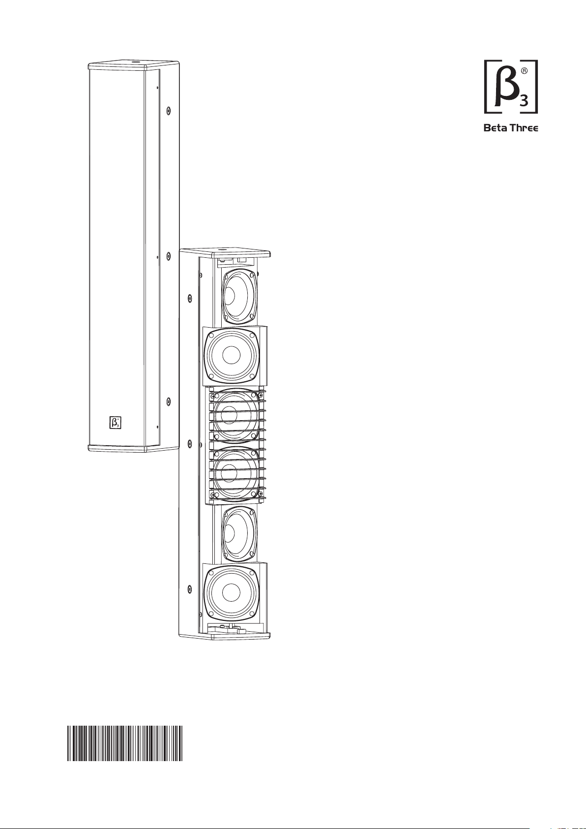
T4.6
4 x 6 line array full
range column speaker
User Manual
UM - T 4 . 6 - 2 0 0 9 0 5 0 7 v e r A
Page 2
SAFETY INSTRUCTIONS
PLEASE READ THIS MANUAL FIRST
Thank you for a buying product. Read this manual first as it will help you operate the system properly. Please keep this manual
for future reference.
WARNING:
ATTENTION: Don't refit the system or spare parts without being authorized as this will .void the warranty
WARNING: Don't (such as candles) the equipment.place naked flames close to
Read the instruction first before using this product.
1.
Please keep this manual for future reference
2.
Pay attention to all warnings.
3.
Obey all operating instructions.
4.
Do not expose this product to rain or moisture.
5.
Clean this equipment with a dry cloth.
6.
Do not block any ventilation openings. Install according to instructions .
7.
Do not install this product near any heat source, such as , heater, burner, or any other equipment with heat radiation .
8.
Only use spare parts by manufacturer.
9.
Pay attention to the safety symbol on the of the cover.
10.
This product must be installed by professionals. When using hanging brackets or rigging other than those supplied with
the product, please ensure they comply with the local safety codes.
The exclamation point within an equilateral triangle is intended to alert you to the presence of important
operating and servicing instructions.
manual
manufacturer's
a
supplied the
outside
1
Page 3

T4.6
T ser ies ful l range spe aker lin e array col umn
CONTENT
CONTENT
PRODUC T INTRODUCTION
Main Features
Product Description
Applications
CONNECTION
Push Terminals
System Reference Diagram
INSTALLATION
Optional Installation Accessories
Installation Options
TECHNICAL SPECIFICATIONS
Specifications
Frequency Response and Impedance Cur ve
Dimensions
3
3
3
3
4
4
4
5
5
5
6
6
6
7
Product information updated without
notification, please visit www.elderaudio.com for
latest update.
may be
2
Page 4

PRODUCT INTRODUCTION
T4.6
4 x 6 li ne array full range column speaker
Main Features
A vertical line array of 6 x 4" full range transducers providing
high fidelity sound.
Frequency response 90H z-16KH z(-3dB).
Sensitivity 92dB, Max SPL 115dB.
Dispersion 180 x 25°.
Rated power 180w, max power 720w.
Plywood cabinet with durable .textured paint finish
Can be installed alone or stacked in multiples using the
optional accessories.Suitable for many venues including
inside and outside undercover environments.
Patents pending for central diffuser plate.
T ser ies ful l range spe aker lin e array col umn
T4.6
Designed for high speech intelligibility and natural
sounding music.
Quick install U bracket included.
Product Description
β3
The T4.6 line array full range column speaker is one
o three speakers in the T Series. This attractively designed, f
180 W RMS , in no vat ive s pea ke r d eli vers hig h spe ech
intelligibility and natural sounding music in a wide range
of applications through its 4" full range drivers. A vertical
line array of 6 drivers provides control over a hori zontal
and vertical pattern of 180 x 25 and reproduces the critical
vocal range 90Hz-1 6kHz without requi ring a proc essor.
A diffuser plate ( patent pendi ng) is fitted to the centre
d river s t o a ss ist wi th t he vertical pa tte rn c on tro l.
The T4.6 speaker can either be used in singles, multiples
or stacked using the optional accessories in many indoor
applications such as Houses of Worship, Shopping Malls,
Transport Terminals, Theme Parks, Meeting Rooms, Schools,
Small Auditoriums. When stacking the T4.6 end on end to
create a taller line a rray the height of the line array must
correspond to the ear height range of the listeners in both
seated or standing positions.
The T4.6 is manufactured from 15 mm plywood meeting a
tensile strength of 3500N and is finished in either black or
white using a very durable textured paint. The metal speaker
grill is powder coated and passes all rust resistance tests.
o o
Adding the optional line transformer accessory makes the
T4.6 line array speaker very versatile in 70/100v systems.
To enhance the already great performance of the T4.6 you
can use the EQ filters provided.
Applications
churches/temples
multifunction halls
meeting rooms
schools
small auditoriums
shopping malls
transport terminals
The T4.6 is shipped with a quick install U bracket.
theme parks
3
Page 5

T4.6
T ser ies ful l range spe aker lin e array col umn
CONNECTION
The T4.6 rear panel has two input connectors. You can choose to use either the 4 way push terminal connector or the NL4
speakon connec tor. The two connectors are paralleled for through connection.
Push Terminals
+
LOW
-
+
LOW
-
+
LOW
-
+
LOW
-
+
LOW
-
+
LOW
-
1+ 1-
Speakon NL4
2+ 2-
1-
2+
1+
1+ 1- INPUT
2+
1+
1+
NL4
2-
1-
1-
2-
System Reference Diagram
Processor (Optional EQ curves available on CD)
RECALL
/ENTER
DISPLAY
UP
DOWN
POWE R
21
INPUT
COMP
OVER
-6
-10
-20
-40
MUTE
MUTE MUTE MUTE MUTE MUT E MUT E MUT E
LIMITER
LIMITER
IN-1
OVER
IN-2
-6
HF
-10
MF
-20
LF
-40
SLF
CBA D E F
LIMITER
IN-1
OVER
OVER
IN-2
-6
-6
HF
-10
-10
MF
-20
-20
LF
-40
-40
SLF
IN-1
IN-2
HF
MF
LF
SLF
OUTPUT
LIMITER
IN-1
OVER
IN-2
-6
HF
-10
MF
-20
LF
-40
SLF
LIMITER
LIMITER
IN-1
OVER
IN-2
OVER
-6
-6
HF
-10
-10
MF
-20
-20
LF
-40
-40
SLF
PROGRAM
IN-1
STATUS
IN-2
REMOTE/ID
HF
MF
LF
SLF
LOCK
T4.6
INPUT
SIGNAL GND
PIN1:
SIGNAL +
PIN2:
PIN3:
SIGNAL -
CHA
BRIDGE IN
LF FILTER
MODE
BRIDGE
50HZ
PARALLEL
25HZ
5HZ
STEREO ON
CHB
CLIPLIM ITER
Serial n o:
OUTPUT ASSI GNMEN T:
CHA:
PIN 1+ :
PIN 1 - :
PIN 2+ :
PIN 2 - :
BRIDGE MON O OUTPU T:
PIN1+ : SIGNAL
CHA :
-
A
+
GROUND
OFF
OFF
ON
CHA SIGNAL
CHB SIGNAL
CHB:
PIN 1+ :
CHB GND
PIN 1 - :
CHA GND
CHB SIGNAL
PIN 2+ :
CHB GND
PIN 2 - :
PIN2+ :
GND
CHA OUTPU T
+
-
BRIDGE
+
B
-
CHB OUTPU T
!
CAUTION
RISK OF ELECTRIC SHOCK
DO NOT OPEN
FUSE
Special design for big power!
POWER
CABLE
T4.6
Warning: Please make sure the speaker impedance and polarity match the amplifiers.
44
Page 6

INSTALLATION
T ser ies ful l range spe aker lin e array col umn
T4.6
Optional Installation Accessories
The T4.6 cabinet has 3 flying points, plus a stand mount
ad ap tor to ensure fa st and ea sy installation. To install
stacked speakers there are an optional coupling brackets.
1.Wall bracket
2.Speaker coupling brackets
Installation Options
1.Flying
Ceiling mount
2. Stand mount
Extensi on moun t
Wall m ount
3. Speaker c ou pling
3.Stand mount adaptor
4.Tripod
Warning: Always ensure the mounting accessories
safety factor is not less than 5:1 or that it meets the
local standards.
5
Page 7

T4.6
T ser ies ful l range spe aker lin e array col umn
TECHNICAL SPECIFICATIONS
Specifications
Product:
Transducer:
Frequency Response(-3dB):
Frequency Response(-10dB):
Sensitivity(1W@1m):
Maximum. SPL(1m):
Power:
Dispersion Angle(HxV):
Rated Impedance:
Cabinet:
Installation:
Paint:
Grill:
Connec tor :
Dimension(WxDxH):
Packing Dimension(WxDxH):
Net Weight:
Gross Weight:
Optional Accessories:
Passive Wooden Speaker
6 x 4'' Full range transducers
1
90Hz-16kHz
80Hz-17kHz
2
92dB
3
115dB/121dB( )PEAK
180W (RMS)
4
360W (MUSIC)
720W (PEAK )
°
180 x 25
°
8 ohms
15mm plywood construction
Mounting U bracket included and
optional mounting points provided.
White durable textured finish
White powder coated ,
0.8mm steel mesh.
4-Push terminal and 1 NL4 Speak on
135x169x800mm
(5.3x6.7x31.5in)
240x205x900mm
(9.4x8.1x35.4in)
9kg (19.8 lbs)
10kg (22.0 lbs)
Coupling bracket, Stand adaptor,
Tripod
Speaker Testing Method
1. Frequency Response
Use Pink noise to test the speaker in the anechoic chamber, adjust the
level to make the speaker work at its rated impedance and set the output
power at 1W, then test the frequency response 1m away from the
speaker.
2. Sensitivity
Use full range Pink noise which has been modified using an EQ
cur ve to test the speaker in the anechoic chamber, increasing the
signal to make the speaker work at its rated impedance and set the
power outp ut at 1W, t hen test the sensiti vity 1m away from the
speaker.
3. MAX.SPL
Use full range Pink noise which has been modified using a n EQ
curve to test the speaker in the anechoic chamber , increase the
si gna l to mak e the sp eaker work at it s maxim um power output
level, then test the SPL1m away from t he speaker.
4. Rated Power
Us e Pi nk noise to the IEC# 26 8- 5 st andard to test the speaker,
i ncrease the signal for a continuous peri od of 1 00 hours, the
rated pow er is the p owe r whenthe s peaker wi ll show no visible
or measurable damage.
Technical Specifications
120
110
100
90
Sensitivity (dB)
80
70
20
6
50 100 200 500
1k
Frequency (Hz)
Frequency response curve (with control)
Frequency response curve (without control)
Impedance curve
2k
5k 10k 20k
90
25
7.5
4
Impedance (Ohms)
Page 8

TECHNICAL SPECIFICATIONS
Dimensions
[6.65in]
169mm
Top view
135mm
[5.32in]
T ser ies ful l range spe aker lin e array col umn
T4.6
300mm
100 mm
[11.81in]
[3.94in]
Side view
800mm
[31.50in]
Front view
93mm
[3.66in]
Back view
Bottom view
52mm
[2.05in]
7
Page 9

Notes:
Page 10

 Loading...