

Page 1
COMPACT LINE ARRAY SOUND
REINFORCEMENT SYSTEM
USER MANUAL
ED-B3-MA-071228-001
Page 2
TABLE OF CONTENTS
Description
Acoustic Features
Installation
Connection
Amplifier Module With DSP
Software Application Guide
Application Examples
Safety Information
Warranty
Technical Specifications
Page 3
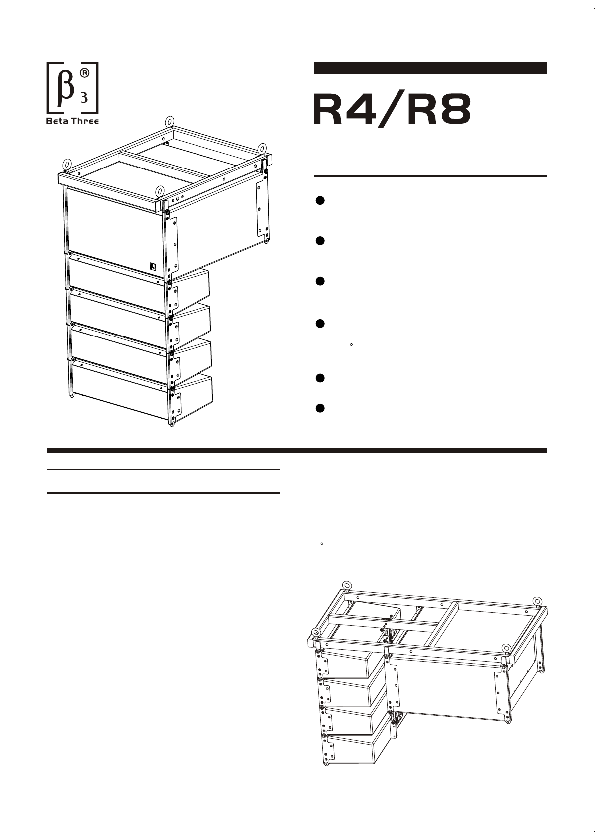
COMPACT LINE ARRAY SOUND
REINFORCEMENT SYSTEM
Compact design suitable for various application
situations
Up to 40kHz frequency range due to adoption
of ribbon tweeter
Low distortion due to utilization of unique thin
foam surround & specially coated paper cone
Multi-speaker array configurable for flying in
different venues, with splay angle adjustable
by 1 increment
600W DSP active amplifier
RS-232/USB/RS-485 Portes available for
system control
DESCRIPTION
R4/R8 is specially designed for luxury cinema,
large-sized meeting room, multi-functional hall, church
and auditorium applications. The system consists of
1 active subwoofer and 4 full range speakers which
can form multi-cluster configurations.
R4/R8 is designed by applying line array concept. It
features compact dimensions and easy to handle design.
The built-in 600W amplifier and DSP make it available
for use at any moment when connected to sound
resource. System control over each cluster at frequency
response, crossover point & slope, delay, gain and
limit protection can be achieved by connecting the
speaker system to PC via RS-232 port. Adoption of
ribbon tweeters offers a wide-range frequency response
to up to 40kHz. The tweeter's impedance and phase
response curves are nearly ideal horizontal lines.
The light moving mass of milligrams ensures excellent
impulse response. Utilization of the unique thin foam
surround and specially coated cone paper has reduced
the distortion rate effectively. The active subwoofer
applies Low Distortion, Linear Amplification, and DSP
technologies. Input signals are amplified by the built-in
pre-amplifier, then processed and distributed by DSP,
finally output via power amplifier to the subwoofer and
the full-range speakers, which forms an integrated
system.
The flying hardware is designed to fit different application
situation flexibly with the splay angel adjustable by
1 increment vertically.
1
Page 4
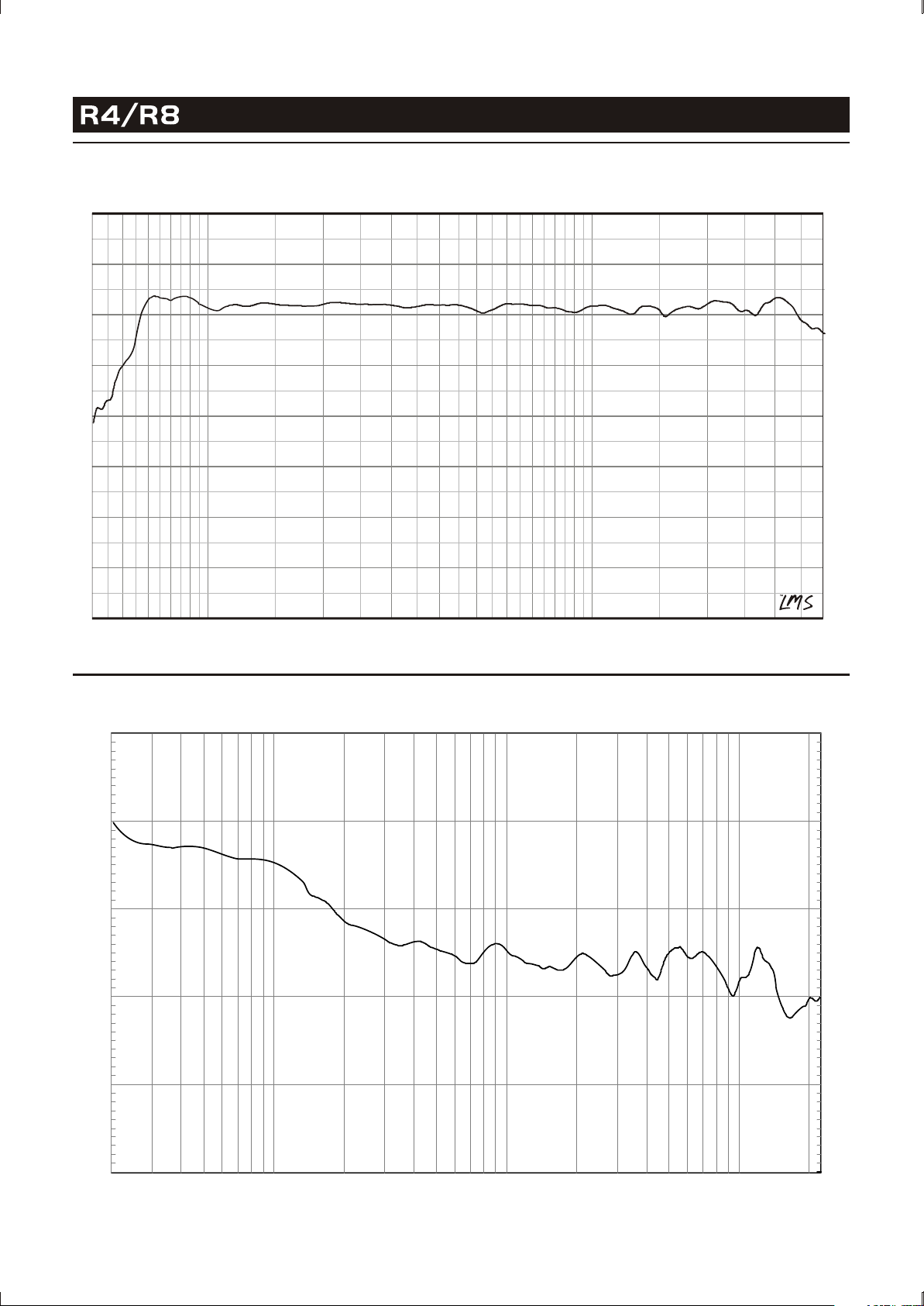
FREQUENCY RESPONSE
COMPACT LINE ARRAY SOUND REINFORCEMENT SYSTEM
100
95
90
85
80
75
70
65
dBSPL
100 Hz
500 Hz
Deg
180
150
120
90
60
30
0
-30
-60
-90
-120
-150
5K
1K
10K 20K 40K
-180
PHASE RESPONSE
1 8 0
D eg
1 0 8
3 6
- 3 6
- 1 08
- 1 80
1 00 1k 1 0k 2 0k Hz20
2
Page 5
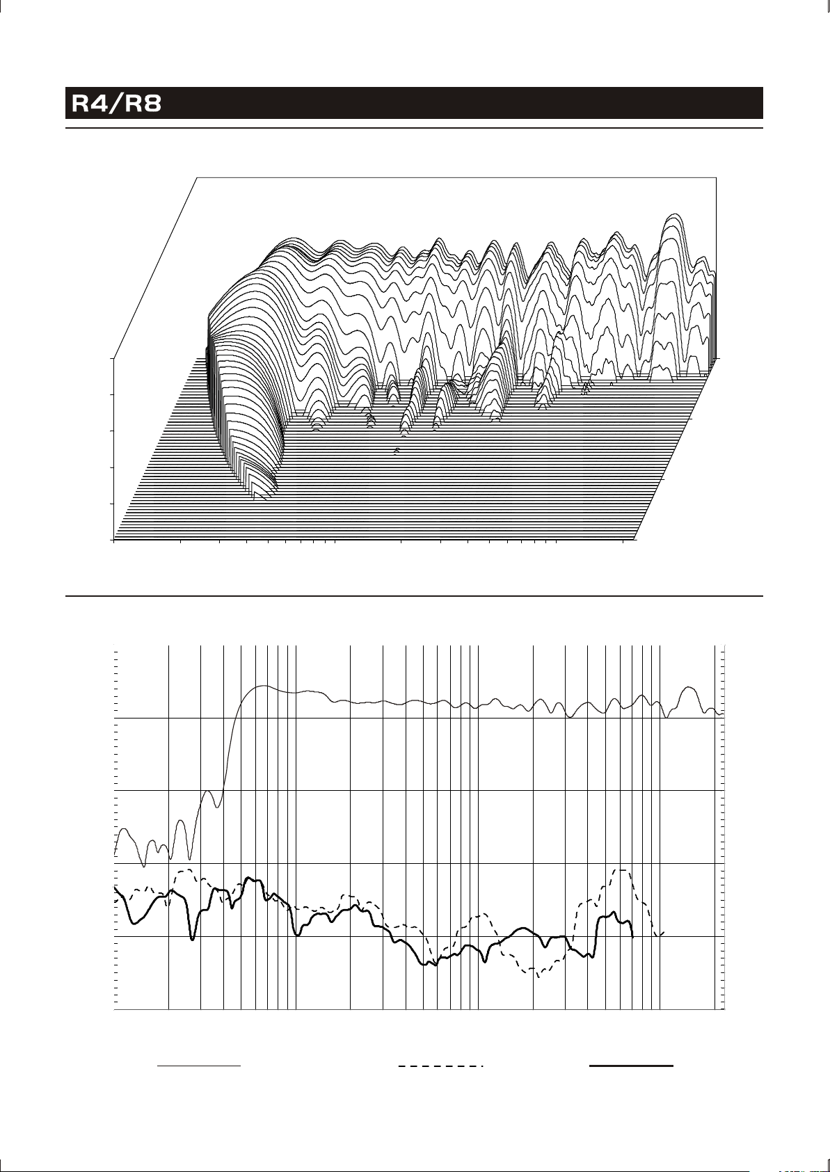
WATERFALL
COMPACT LINE ARRAY SOUND REINFORCEMENT SYSTEM
0
dB
- 5
- 10
- 15
- 20
- 25
2 00 5 00
1 k 2k
5k
1 0k 20k150
5.4
8.0 ms
Hz
THD
1 1 0
d B SPL
9 0 1 0 8
0 .0
2.7
1 8 0
D eg
7 0
5 0
3 0
1 0
1 20 50 1 00 2 00 5 00 1k 2k 5k 1 0k 2 0k Hz10
Frequency Response
3 6
- 3 6
- 1 0 8
- 1 80
2nd Distortion
3rd Distortion
3
Page 6
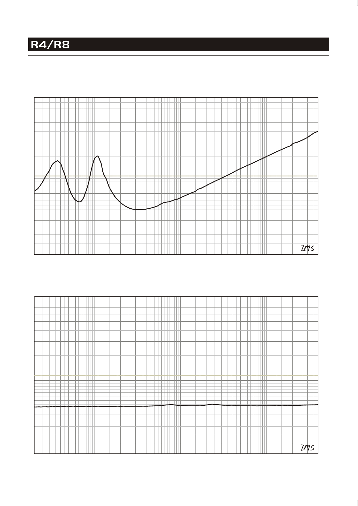
IMPEDANCE CURVE
IMPEDANCE CURVE OF R8
COMPACT LINE ARRAY SOUND REINFORCEMENT SYSTEM
Ohm
50
40
30
20
10
9
8
7
6
5
4
3
2
20 Hz 50 100 200 500
1K 2K
Deg
180
150
120
90
60
30
0
-30
-60
-90
-120
-150
5K
10K 20K 40K
-180
IMPEDANCE CURVE OF THE RIBBON TWEETER
Ohm
50
40
30
20
10
9
8
7
6
5
4
3
2
20 Hz 50 100 200 500
1K 2K
Deg
180
150
120
90
60
30
0
-30
-60
-90
-120
-150
5K
10K 20K 40K
-180
4
Page 7
COMPACT LINE ARRAY SOUND REINFORCEMENT SYSTEM
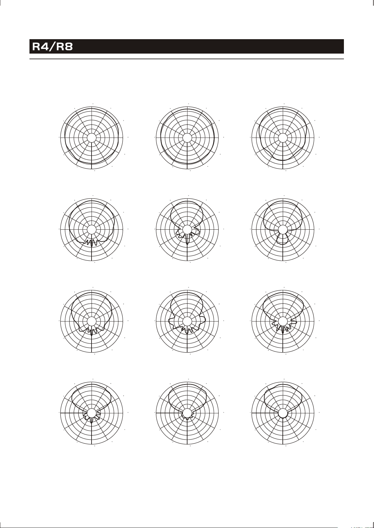
HORIZONTAL DIRECTIVITY
The data of R4/R8 horizontal directivity were collected by testing the speaker system in a big anechoic chamber.
The distance between the testing microphone and the speaker system is 4 meters.
0
330
300
270
240
210
30
60
90
120
150
180
330
300
270
240
210
100Hz
0
330
300
270
240
210
30
60
90
120
150
180
330
300
270
240
210
400Hz
0
180
160Hz
0
180
630Hz
30
60
90
120
150
30
60
90
120
150
330
300
270
240
210
330
300
270
240
210
0
180
250Hz
0
180
1kHz
30
60
90
120
150
30
60
90
120
150
0
330
300
270
240
210
30
60
90
120
150
180
330
300
270
240
210
1.6kHz
0
330
300
270
240
210
30
60
90
120
150
180
330
300
270
240
210
6.3kHz
0
30
60
90
120
150
180
330
300
270
240
210
2.5kHz
0
30
60
90
120
150
180
330
300
270
240
210
10kHz 16kHz
0
180
4.0kHz
0
180
30
60
90
120
150
30
60
90
120
150
The scale is stepped by 6dB increment.
5
Page 8
COMPACT LINE ARRAY SOUND REINFORCEMENT SYSTEM
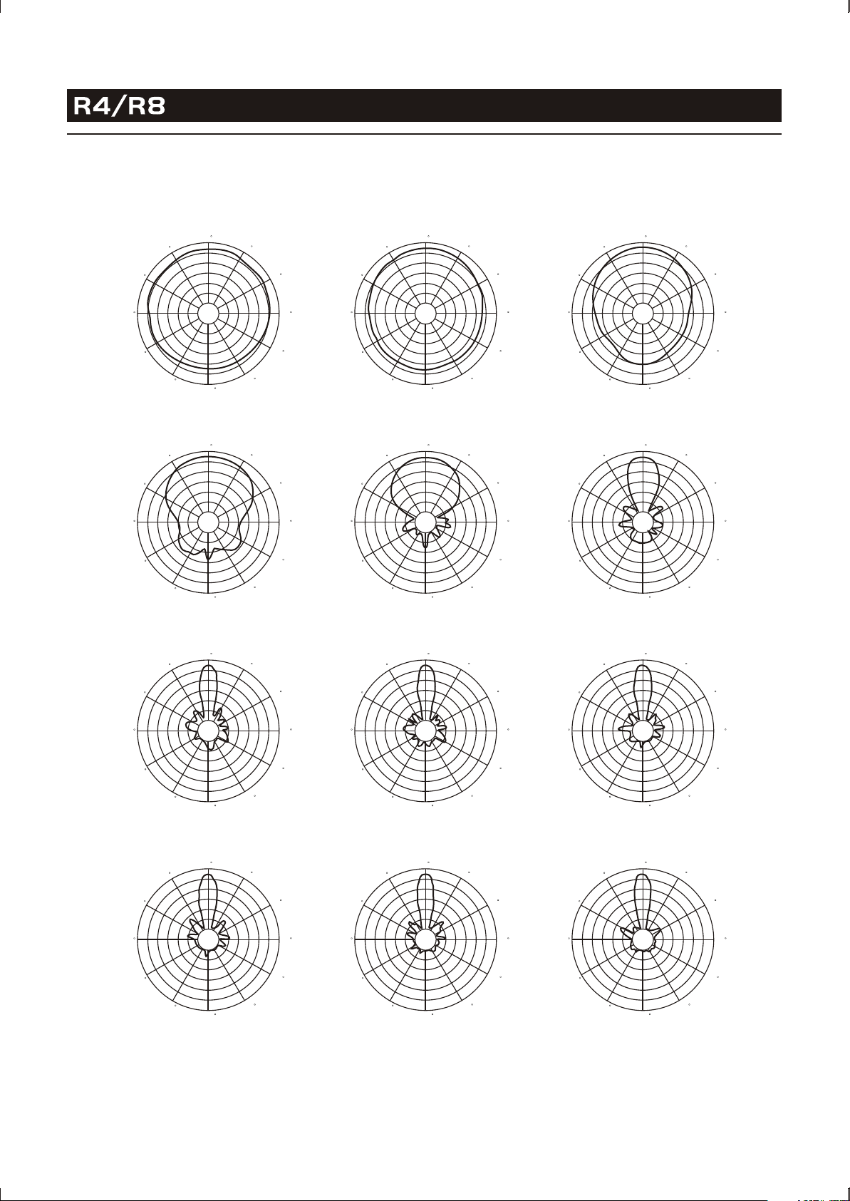
VERTICAL DIRECTIVITY
The data of R4/R8 vertical directivity were collected by testing the speaker system in a big anechoic chamber.
The distance between the testing microphone and the speaker system is 4 meters.
0
330
300
270
240
210
30
60
90
120
150
180
330
300
270
240
210
100Hz
0
330
300
270
240
210
30
60
90
120
150
180
330
300
270
240
210
400Hz
0
180
160Hz
0
180
630Hz
30
60
90
120
150
30
60
90
120
150
330
300
270
240
210
330
300
270
240
210
0
180
250Hz
0
180
1kHz
30
60
90
120
150
30
60
90
120
150
0
330
300
270
240
210
30
60
90
120
150
180
330
300
270
240
210
1.6kHz
0
330
300
270
240
210
30
60
90
120
150
180
330
300
270
240
210
6.3kHz
0
30
60
90
120
150
180
330
300
270
240
210
2.5kHz
0
30
60
90
120
150
180
330
300
270
240
210
10kHz 16kHz
0
180
4.0kHz
0
180
30
60
90
120
150
30
60
90
120
150
The scale is stepped by 6dB increment.
6
Page 9
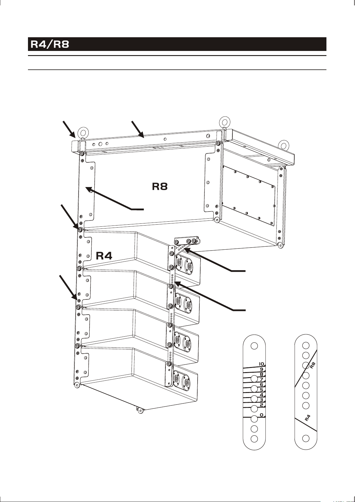
INSTALLATION
COMPACT LINE ARRAY SOUND REINFORCEMENT SYSTEM
Ring
M5 Thumb
Screw
M5 Small
Head Screw
Flying Frame
Front Link
R4-R8 Link
R4 Back Link
R4 Back Link
7
R4-R8 Link
Page 10
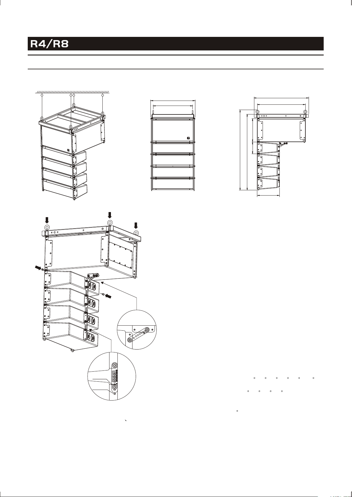
INSTALLATION
INSTALLATION METHOD 1
COMPACT LINE ARRAY SOUND REINFORCEMENT SYSTEM
492
437
2
6
2
3
3
0
2
1
0
5
9
8
608
536
250
(4) Demount the two M5 thumb screws at the top of
1
the front side of R4.
(5) Insert the two R8 Front Links into the U grooves
along the left & right front edges of R4, make sure
the two screw holes on both sides are aligned, and
tighten the screws through the holes.
(6) Insert one end of the R4-R8 Link into the U groove
on the back of R4 and the other end into the U
groove on the bottom of R8, make sure the two
screw holes at both ends of the link are aligned
with the corresponding holes in the U grooves,
mount the two M5 thumb screws, and tighten them
(see Figure3).
2
Alignment of the white scale lines on the R4-R8
link with the edges of the two U grooves indicates
successful mounting.
3
No.1 Hole
No.2 Hole
4
ONE CLUSTER FLOWN VERTICALLY
(1) Open the package and take out R4 R8 speakers
and the accessories.
(2) Mount the four M8 rings to the flying frame (see
Figure 1).
(3) Demount the two M5 thumb screws at the bottom
of R8, and take out the R4-R8 Link.
SPLAY ANGEL ADJUSTMENT
Turn R4 speaker together with its back link (R4 Back
Link), make sure the right scale line marked on the R4
Back Link is aligned with the edge of the U groove at
the back of R4 speaker (The numbers marked besides
each scale line indicate different splay angles). Then
insert the M5 thumb screw through the aligned holes
of the R4 Back Link and the U groove at the back of
the speaker (Alignment with Number 1 hole in the
groove is required when 0 /2 /4 /6 /8 /10 of
splay angle is wanted, and alignment with Number 2
hole is required when 3 /5 /7 /9 of splay angel
is wanted).
For example, if the splay angle between two R4 speakers
is designed to be 5 , the scale line marked with the
number of 5 on the R4 Back Link must be aligned to
the bottom edge of the groove on the back of the top
speaker, then a certain hole in the R4 Back Link will
be found to be aligned with Number 2 hole in the groove
at the back of the top speaker. Insert a M5 thumb screw
through the two aligned holes and tighten it.
8
Page 11

INSTALLATION
COMPACT LINE ARRAY SOUND REINFORCEMENT SYSTEM
INSTALLATION METHOD 2
Multi Clusters Flown Vertically
(maximum 4 Clusters)
INSTALLATION METHOD 3
Cluster stacked with R8 at the bottom.
(1) Open the package, and take out R4 R8 speakers
and the accessories.
(2) Mount the four M8 rings to the flying frame.
(3) Demount the two M5 thumb screws at the bottom
of R8, and take out the R4-R8 Link. Disassemble
the U grooves and remount the two M5 small head
screws in the original holes.
(4) Disassemble the flying frame of another R8, mount
this R8 to the bottom of the first R8 by tightening
M5 thumb screws accordingly.
(5) Demount the two M5 thumb screws at the top of
the front side of R4.
(6) Insert the two R8 Front Links into the U grooves
along the left & right front edges of R4, make sure
the two screw holes on both sides are aligned, and
then tighten the screws through the holes.
(7) Insert one end of the R4-R8 Link into the U groove
on the back of R4 and the other end into the U
groove on the bottom of R8, make sure the two
screw holes at both ends of the link are aligned with
the corresponding holes in the U grooves, mount
the two M5 thumb screws, and tighten them (see
Figure3). Alignment of the white scale lines on the
R4-R8 link with the edges of the two U grooves
indicates successful mounting.
(8) Attach one or more clusters of R4 to the bottom of
the installed R4 accordingly.
9
Page 12

INSTALLATION
COMPACT LINE ARRAY SOUND REINFORCEMENT SYSTEM
INSTALLATION METHOD 4 (THE LONG FLYING FRAME IS OPTIONAL)
1
2
3
5
No.1 Hole
No.2 Hole
One cluster flown from front to back
(1)
Open the package, take out R4, R8 speakers and
the accessories.
(2)
Open the package of the long flying frame, take out
4
INSTALLATION METHOD 5
Multi clusters flown from front to back
(maximum 4 clusters)
the frame and accessories.
Mount the M8 rings to the long flying frame (see
(3)
Arrow 1), and insert the R4 Back Link inside the
middle groove of the long flying frame (see Arrow 2).
Put the long flying frame upside down (with the rings
(4)
downside).
(5)
Demount the two M5 thumb screws at the top of
the front side of R4.
(6)
Put the R4 upside down. Insert the Front Links of
the long flying frame into the U grooves along the
left & right front edges of R4, make sure the two
screw holes on both sides are aligned, and then
tighten two M5 thumb screws through the holes.
Turn the R4 speaker, make the scale line marked
(7)
with the number of 0 on the R4 link attached to the
long flying frame aligned with the bottom edge of
the U groove, then insert a M5 thumb screw through
the two aligned holes and tighten it (see figure 4).
(8)
Demount the two M5 thumb screws at the bottom
of R8, and take out the R4-R8 Link. Then demount
the four M5 thumb screws connecting the R8 and
the short flying frame, and disassemble the short
frame.
(9)
Put the R8 upside down, insert the four links on
the back of the long flying frame inside the U grooves
of the R8 and make sure the screw holes are aligned
accordingly. Then mount and tighten two M5 screws
through the holes.
10
Page 13

CONNECTION
COMPACT LINE ARRAY SOUND REINFORCEMENT SYSTEM
Power Input
R4 Speaker Output
R4 Input
Signal Input
R4 Output
11
R4 Input
R4 Input
R4 Input
R4 Output
R4 Output
Page 14

COMPACT LINE ARRAY SOUND REINFORCEMENT SYSTEM
AMPLIFIER MODULE WITH DSP
The amplifier module embedded in the system has been made some optimization based on previous version.
RS-485 and USB port are added into it for computer connection, it will be very convenient for user to
configurate system parameters by software. Built-in stepless cooling fan(Speed will be changed according to
the temperature automatically to make sure system work stably), overload protection, short circuit protection
(avoid the damage of amplifier when abnormal loading occurred) and temperature protection(when the
temperature is over the normal range, DSP will attenuate the output, if temperature is normal ,then amplifier s
output recover to normal status). give the user the complete guarantee. The peak indication function has been
improved on R8 , the new version has the AD overload indication and DSP overload indication, it will be very
easy for user to control this system. Adopted more advanced IC bring a big progress on Audio performance.
230V T6.3AL,50Hz/60Hz
1 2 3 4 5 6 7
13
1 Power Supply Switch
2 Fuse
3 Power Supply Input
S.N.
Elder Audio Manufacture Co.,Ltd
4 Signal Output (NL4 socket)
5 USB Port
6 RS-232 Port
RS-485
INPUT
OUTPUT
USB
RS-232
11 12
10
OUTPUT
VOLUME
LINE
INPUT
PEAK
0dB
9
8
7 Volume
8 Signal Peak Indicator
9 RS-485 Output
COMPACT LINE
ARRAY SOUND
REINFORCEMENT SYSTEM
STANDARD CONFIGURATION:
1 R8(ACTIVE SUB)+4R 4(FULL RANGE)
Several standard systems can be paralleled
SYSTEM SPECIFICATION:
FREQ. RESPONSE
MAX SPL
H. COVERAGE
V. COVERAGE
LF AMPLIFIER POWER
HF AMPLIFIER POWER
LINE INPUT SENSITIVITY
DRIVER QUANTITY
POWER REQUIREMENT
POWER MAX
DIM.(W DH )
NET WEIGHTNET WEIGHT
50Hz-20kHz
115dB/121dB(PEAK)
30- 90
300W RMS
754 RMS
+4dBu
R8: 8" 2
4" 2+RIBBON DRIVER1
230V T6.3AL,50Hz/60Hz
1100W
4926 089 00mm
45kg
120
10 RS-485 Input
11 Line Output
12 Line Input
13 Different AC input versions are available for this product,
please pay attention to the AC mark on the product.
12
Page 15

COMPACT LINE ARRAY SOUND REINFORCEMENT SYSTEM
SOFTWARE APPLICATION GUIDE
How to get the software
The software is stored in the CD with equipment packaging. The latest version also may be downloaded
from the company website.
Software installation
System requirement: Microsoft Windows 98/XP or above version. Display resolution should be 1024*768
or above. The computer must have a RS-232 port or USB port. Run the
(V1.34).msi
file, according computer's setup guide to install the control software.
Equipment connection
Connect the equipment to computer by RS-232, if the computer has not the RS-232 interface, you may
use USB port (after connection, the computer will indicate that new device is found, then you may install
the USB driver located in driver directory of the CD.""
Software operation guide
1. Run the software(Active Speaker Controller) from program menu in the windows start button, the
following interface will be shown, See Figure 1:
""Active Speaker Controller
Figure 1
This interface includes all function modules about the equipment, menu description as following:
1.1> File: Open the configuration files, or Save current configuration as a file into computer;
1.2> Communications: Connect ("Enable Communications") or Disconnect ("Disable
Communications") the equipment, Operation details refer to following description.
13
Page 16

COMPACT LINE ARRAY SOUND REINFORCEMENT SYSTEM
SOFTWARE APPLICATION GUIDE
1.3> Program: Obtain the information of currently used configuration file (Disconnection status),or the
information of current program in the equipment(Connection status).
On disconnection status, only "Display Current Program No", "Display Current Program Name" ,
"Edit Current Program Name" and "Load Factory Default Configuration" may be valid. All
changes do not affect the equipment internal program settings.
On connection status, all items are valid under the "Program" menu. If selecting the" Edit Current
Program Name" command, the current program name auto saved in the equipment;
If selecting the "Load Factory Default Configuration " command, the current program is overwrite
by the default setting automatically (! Attention Please: this operation will overwrite the current
program configuration, before executing this operation, please make sure you really ready to load
factory default settings). Details of other function items (such as"List Program & Recall" and "Save
as current program in device")under the "Program" menu, please refer to following description.
1.4> Device: Modify the device information, and saved in the equipment automatically, only valid on
connection status;
1.5> Help: the control software version information.
2.Connecting the device.
2.1> Three hardware connection solution(USB,RS-232,RS-485) are available for your connecting;
2.2> After connected the device with computer port by connector, Click the "Communications", select
"E nable Communications" command to start the connecting. See Figure 2:
Figure 2
The software will search the connected (hardware connection) device automatically, Search
Device... will be shown at the bottom of interface's status bar, see Figure 3:
"
"
14
Page 17

COMPACT LINE ARRAY SOUND REINFORCEMENT SYSTEM
SOFTWARE APPLICATION GUIDE
If found device, shown as Figure 4:
Figure 3
Figure 4
Devices online are listed at left, the right part shows the information of the device chosen by user.
If user want to use the config file that opens from computer, Download Program Data to Device
must be chosen(the operation execute transmitting the parameters into Device's RAM, if no further
save into device operation, the parameters will be lost after the device power off). If user chose
Upload Program Data From Device , it will load the current program that stored in device to PC.
""
Select the left device that you will want to connect, click the Connect button to start connecting.
(! Attention please: If connect with several devices, each device must a ID number which is exclusive
in the system)
""
""
15
Page 18

COMPACT LINE ARRAY SOUND REINFORCEMENT SYSTEM
SOFTWARE APPLICATION GUIDE
After connecting successfully, the software will update the display automatically, and show the
information of currently connected device, and current program used by device, see Figure 5:
Figure 5
On above interface, click corresponding function button, and executing those operation that you want.
3. Recall or Save the configuration file.
When the device used in different places, the different configuration file are necessary. Two ways are
available for user to recall or save the configuration file.
3.1> Save as a file, When user finish the adjustment, the parameters may be saved as a file into PC through
Save As in the file menu, see Figure 6:""
When you ready to load the config file for later using on other device, you may open the file under the
File menu.""
Figure 6
16
Page 19

COMPACT LINE ARRAY SOUND REINFORCEMENT SYSTEM
SOFTWARE APPLICATION GUIDE
3.2>User also may save the parameters in the device, total max six programs may be saved through
Save as current program in device under program menu. See Figure 7:""""
Figure 7
According to the different file source, the two ways are available for recall the existing configuration file.
For the file saved in the computer, it may be recalled from Open under File menu. Then connect
the equipment, choose Download program data to device in pop-out dialog box, see Figure 4.
3.3> For the files(or programs) in the device, it may be recalled through List Program&Recall in Program menu.
See Figure 8
""
"" ""
""
Figure 8
Select the program you want to use in the pop-out dialog box, then click Recall button, the software
will update the display automatically, and the device using the program that has been recalled.
""
17
Page 20

COMPACT LINE ARRAY SOUND REINFORCEMENT SYSTEM
SOFTWARE APPLICATION GUIDE
4. Change the information of the device that is online.
Device information means the identifier of device, such as the description of device position etc, Include ID
and device name. After connecting, it may be changed through clicking Edit current device information
in device menu, See Figure 9:
! Attention: ID number is only available for number 1~10, that's to say only max 10 device may be
connected one RS-485 Net. The max length of name is 14ASCII characters.
""
Figure 9
5. Change the current program name.
Click Program menu, choose Edit current program name to change the program name, See Figure 10:"" " "
Figure 10
18
Page 21

COMPACT LINE ARRAY SOUND REINFORCEMENT SYSTEM
SOFTWARE APPLICATION GUIDE
6. Disconnection.
After finishing the adjustment of parameters, the current parameters may be saved into the device for the
next power on operation. If user does not save the program into device, all the changes based on previous
parameters will not be saved. Choose "Disable communications" under "communications" menu to
disconnection. Please see the figure 11:
Figure 11
19
Page 22

COMPACT LINE ARRAY SOUND REINFORCEMENT SYSTEM
APPLICATION EXAMPLES
1.Save current program as another program with new name.
If user want to save as another program with new name, user should select "program save as" command first,
then select "edit current program name" command.
Please see details as below example.
1 After uploading the Program No.1 from the device to the PC, then modify those parameters that you want,
then select the "Save As Current Program In Device" command in "Program" Menu:
2) Then select the Program Number that will be saved into device:
Then click "OK" button, the Program No.1 has been saved as Program No.2,and the current program
auto changed to No.2(and the Program No.1 just be uploaded to PC has not been changed)
20
Page 23

COMPACT LINE ARRAY SOUND REINFORCEMENT SYSTEM
APPLICATION EXAMPLES
3) Then select "Edit Current Program Name" command in "Program" menu:
4) Then on the "Set Current Program Name " interface, edit the program name as you want:
Changed to "my concert hall" as the bellow figure
21
Page 24

COMPACT LINE ARRAY SOUND REINFORCEMENT SYSTEM
APPLICATION EXAMPLES
5) Click "OK" button, thus the "Current Program Name:" on the main interface has been changed to
"my concert hall".
6) Select " List Program & Recall" command in "Program" menu, the result in the program list of the
device now as bellow figure:
22
Page 25

COMPACT LINE ARRAY SOUND REINFORCEMENT SYSTEM
APPLICATION EXAMPLES
2.Save the program which is uploading from device as a file in computer.
Operation for file is only effected on disconnection status. If on connection status, "Edit current program
name" is immeditaly valid(auto save into the device). If want to use the config file for later use with another
device, You may modify the "program name" on disconnection status.and save as another file. Then
download the new config file into device, then "save as" another program or current program into device.
Operation Example Steps:
1) After upload the Program No.3 from the device to the PC, then modify some parameters that user want
to do, if adjust OK, then select "Disable Communications" command in "Communications" menu.(on
disconnection, those modification does not effect to program in device)
2) If want to change the name, select "Edit Current Program Name" in "Program" menu:
23
Page 26

COMPACT LINE ARRAY SOUND REINFORCEMENT SYSTEM
APPLICATION EXAMPLES
Edit Program Name to "my modified program 3", then click "OK" button.
3) Then select "Save As" command in "File" menu.
4) In the "File Name(N) " frame, input "next hall.asc " ,then click "Save(S) " button.
24
Page 27

COMPACT LINE ARRAY SOUND REINFORCEMENT SYSTEM
APPLICATION EXAMPLES
3.Downloading a file into device, and save as program in device.
1) After downloading the config file into DEVICE(only to RAM, before select "Save As Current Program In
Device" command, the parameters have not saved into FLASH ROM!)
2) Select "Save As Current Program In Device" command in "Program" menu:
3) Then select the No(for example No.4) that you want to save in,
25
Page 28

COMPACT LINE ARRAY SOUND REINFORCEMENT SYSTEM
APPLICATION EXAMPLES
Click "OK" button ,then the parameters of config file(next_hall.asc) have been saved as program No.4 in
device. The "Current Program No" and the "Current Program Name" are corresponding to File, as bellow
figure:
List as below
26
Page 29

COMPACT LINE ARRAY SOUND REINFORCEMENT SYSTEM
SAFETY INSTRUCTIONS
DO NOT OPEN THE COVER
Do not open the cover to avoid the risk of electric shock
caused by high voltage parts in the product. Any problems
caused by user's wrong actions are out of warranty.
DO NOT DAMAGE THE POWER CORD
Please hold the plug when pull out or plug in the cord.
Do not pull out or touch the cord with wet hand, or
it will cause the risk of electric shock. Power supply cords
should be routed so they are not likely to be walked
upon or pinched by items placed on or again st them.
When removing the cord from a power outlet be sure
to remove it by holding the plug attachment and not
By pulling on the cord.
AVOID OBJECT AND LIQUID ENTRY
Take care that objects do not fall into and that liquids
are not spilled into the inside of the product.If the object
or liquid enter the product,please ask qualified personnel
to check it.
LIMITED WARRANTY
If malfunction occurs during the specified warranty
period from the date of original purchase, the product
will be repaired or replaced without charge by Elder
Audio.
The Limited Warranty does not apply to:
(a) exterior finish or appearance;
(b) certain specific items described in the individual
product data sheet or owner's manual;
(c) malfunction resulting from use or operation of the
product other than as specified in the individual
product data sheet or owner's manual;
(d) malfunction resulting from misuse or abuse of the
product;
(e) malfunction occurring at any time after repairs have
been made to the product by anyone other than
Elder Audio Service or any of its authorized service
representatives.
To obtain warranty service, a customer must deliver
proof of purchase of the product in the form of a bill of
sale or receipt invoice.
R4/R8 Speakers and Speaker Systems are guaranteed
against malfunction due to defects in materials or
workmanship for a period of three (3) years from the
date of original purchase. The Limited Warranty does
not apply to burned voice coils or malfunctions such
as cone and/or coil damage resulting from improperly
designed enclosures. Additional details are included
in the Limited Warranty statement.
ABNORMAL STATUS
In the event of abnormal noise and smell, please put
off the power supply and pull out the cord, please ask
qualified personnel to check it.
NONUSE FOR A LONG TIME
When nonuse it for a long time, please put off the power
supply and pull out the cord to avoid the unexpected
dangers.
R4/R8 Accessories are guaranteed against malfunction
due to defects in materials or workmanship for a period
of one (1) year from the date of original purchase.
Additional details are included in the Limited Warranty
statement.
R4/R8 Flying Hardware (including enclosure-mounted
hardware and rigging accessories) is guaranteed against
malfunction due to defects in materials or workmanship
for a period of one (1) year from the date of original
purchase. Additional details are included in the Limited
Warranty statement.
Specifications subject to change without notice.
27
Page 30

TECHNICAL SPECIFICATIONS
COMPACT LINE ARRAY SOUND REINFORCEMENT SYSTEM
Frequency Range
Max SLP
Horizontal Dispersion
Vertical Dispersion
Max Constant Power Output For Mid-low Range
Max Constant Power Output For Mid-high Range
Power Max
Line In Sensitivity
608
536
115dB/121dB PEAK
50Hz - 20kHz
()
120
30 - 90
300W RMS
75W 4 RMS
1100W
+4dBu
Driver
Power Suply (Different AC input versions are available
for this product, please pay attention to the AC mark on
the product)
120V/115V/110V/100V~T10AL 50Hz/60Hz
Dimensions (WxDxH)
Net Weight
492
437
R4:4 2 + RIBBON DRIVER 1
240V/230V/220V~T6.3AL 50Hz/60Hz
492 608 900mm
R8:8 2
45kg
900
852
28
Page 31

www.elderaudio.com
 Loading...