

Page 1

Q-Scan PC/DMX
Professional Scanning and Graphics System
For Q-Series Beam Projectors
and other
Beam aperture devices with a standard ¾” module mount.
OPERATIONS MANUAL
Laser Radiation can emit from this product only when attached to a laser source.
This product conforms with 21 CFR 1040 CDRH
WARNING
Read and follow ALL instructions
Carefully before operating this system
Manufactured for OmniSistem Lights and Effects
7819 South 196
253-395-9500 Phone – 253-395-9494 Fax
th
Street, Kent Washington 98032
www.omnisistem.com
Page 2

Table of Contents
Section 1.0 = Introduction – Q-Scan PC/DMX
Section 2.0 = System Orientation – Q-Scan PC/DMX
Section 3.0 = DMX-512 Operation – Q-Scan PC/DMX
Section 4.0 = Sound Activation – Q-Scan PC/DMX
Section 5.0 = Q-Link Software – Q-Scan PC
Section 6.0 = Q-Link Start-up – Q-Scan PC
Section 7.0 = Q-Link – Q-Scan PC (General)
Section 8.0 = Q-Link – Q-Scan PC - Visual Interface (Working within Q-Link PC Software)
Section 9.0 = Q-Link – Q-Scan PC – Theory
Section 10.0 = Q-Link – Quick Start
Section 11.0 = Q-Link – Q-Scan PC/DMX-512 – Modes
Section 11.1 = Q-Link – Q-Scan PC/DMX-512 – Mode 1 Circle Patterns
Section 11.2 = Q-Link – Q-Scan PC/DMX-512 – Mode 2 Line Patterns
Section 11.3 = Q-Link – Q-Scan PC/DMX-512 – Mode 3 Spiral Patterns (Lissajou)
Section 11.4 = Q-Link – Q-Scan PC/DMX-512 – Mode 4 Waves Horizontal
Section 11.5 = Q-Link – Q-Scan PC/DMX-512 – Mode 5 Fans Horizontal
Section 11.6 = Q-Link – Q-Scan PC/DMX-512 – Mode 6 Fans Vertical
Section 11.7 = Q-Link – Q-Scan PC/DMX-512 – Mode 7 Beams Series
Section 11.8 = Q-Link – Q-Scan PC/DMX-512 – Mode 8 Beams Random
Section 11.9 = Q-Link – Q-Scan PC/DMX-512 – Mode 9 Sound Beams
Section 11.10 = Q-Link – Q-Scan PC/DMX-512 – Mode 10 Sound Beams
Section 11.11 = Q-Link – Q-Scan PC/DMX-512 – Mode 11 Sound Tunnels
Section 11.12 = Q-Link – Q-Scan PC/DMX-512 – Mode 12 Sound Graphics
Section 11.13 = Q-Link – Q-Scan PC/DMX-512 – Mode 13 Custom
Section 11.14 = Q-Link – Q-Scan PC/DMX-512 – Mode 14 Text
Section 11.15 = Q-Link – Q-Scan PC/DMX-512 – Mode 15 Specials
Section 11.16 = Q-Link – Q-Scan PC/DMX-512 – Mode 16 Scenes
Section 12 = Q-Link – Q-Scan PC/DMX-512 – Text Editor
Section 13 = Q-Link – Q-Scan PC – PRESET PAGE FUNCTIONS
Section 14 = Q-Link – Q-Scan PC – Scripting Function
Section 15 = Q-Link – Q-Scan PC – Sound Graphics Editor
Section 16 = Q-Link – Q-Scan PC – Scene Mode
Section 17 = Q-Link – Q-Scan PC/DMX-512 – DMX Control Table
Section 18 = Q-Link – Q-Scan PC/DMX-512 – DMX 512 Addressing
Section 19 = Q-Link – Q-Scan PC – SIKA Cable
Section 20 = Q-Link – Q-Scan PC/DMX – Installation and Alignment;
Section 21 = Q-Link – Q-Scan PC/DMX 512 – Safety
(Graphics and Animations)
Page 3

Congratulations on purchasing one of the most versatile laser projection systems available in today’s laser
industry. Keeping with the tradition of Quality the “Q” in Q-Scan says the same. From the housing and
mounting designs, the Q-Link software, Lightspeed
®
animations, and the variety of scan projections the Q-
Scan exceeds all expectations for a compact low cost scan and graphics system.
The Q-Scan was designed to bridge the gap between expensive laser graphics equipment and low cost
scanning technology and succeeded with smashing success.
Features include:
1. Real-time math patterns
2. Beams
3. Fans
4. Tunnels
5. Lightspeed
®
Graphics and Animations
6. Instant text (Position able and Reversible)
7. Beam blanking
8. Closed loop scanners
9. Multi-tasking software
10. Sound control of most modes and aspects
11. DMX-512 control using just 8 DMX channels
12. PC control via 9-pin RS232 serial
13. PC control via 25-pin Digital parallel
14. Remote Keypad control
15. Small package size
16. Low power consumption
Q-Scan Unit Size= 6.5" wide, 5.5" tall, 5.5" deep
Manufactured in a rigid piece metal housing with extruded faceplate.
Back panel configuration:
• 9 Pin RS232 connector
• 25 Pin Parallel digital input connector
• Dual XRL DMX in and through connector jacks
• Power plug for external power pack (5-pin) or 120/240 AC universal (3-pin)
• Select switch for internal Mic enables on position 10 of dipswitch
• 9 position dip switch for DMX-512 base addressing (1=LSB, 9=MSB)
• Microphone hole for local sound input
• Standard Audio mono input jack
• Sound sensitivity adjustment
• LED on indicates unit ready and flashing indicates DMX input receive is active
Dipswitches
The dipswitches located on the back of the Q-Scan do 3 jobs:
1. If powered up as all zeros then a broken circle appears for calibration.
2. Addresses 1 to 511 for the DMX base address uses switches 1-9.
3. Dip Switch 10, if set on, disables the internal microphone.
Page 4

Note: If Audio and Mic are both used then sound adjust controls balance.
DMX functions selected via the base address:
MODE: DECIMAL:
Circle Patterns 0>7
Line Patterns 8>15
Spiral Patterns 16>23
Waves Horizontal 24>31
Fan Horizontal 32>39
Fan Vertical 40>47
Beams Series 48>55
Beams Random 56>63
Sound Graphics 64>71
Sound Beams 72>79
Customs 80>87
Sound Tunnels 88>95
Stored Text 96>103
Sound Fans 104>111
Specials 112>119
Scenes 120>127
Text line1 128>135
Text line2 136>143
Text line3 144>151
Text line4 152>159
Text line5 160>167
Text line6 168>175
Text line7 176>183
Text line8 184>191
Edit line1 192>199
Edit line2 200>207
Edit line3 208>215
Edit line4 216>223
Edit line5 224>231
Edit line6 232>239
Edit line7 240>247
Edit line8 248>255
DMX use is 8 channels (base => base+7) and base can be from 1 to 503.
See QSCAN MODES section for more details about the various modes.
See the DMX Control Table for more DMX details of base+1 to base+7 controls.
Text edit lines 1-8 accesses 8 lines of text, 80 characters each.
Text is edited by selecting the text line 1-8 (DMX base=192+8 per line).
Use fader base+1 to select the character position 1-80 to change.
Use fader base+2 to select a symbol, number, or letter for that position.
Page 5

Place character 255 (square block) at end of line for termination. This will erase any text that appears to the
right of the text block.
Moving mode (base+0) away from text edit locks the changes into place.
The sound sense adjustment (uses a small flat screwdriver):
Full Clockwise = Max Microphone sensitivity, no audio input at jack.
Full Counter Clockwise = Max Audio input sensitivity, no Microphone.
In between these extremes a balance can be set.
Note: The audio input jack accepts standard audio. Peak input is 10 volts.
Note: You may use Sound Graphic #1 to adjust sound sensitivity. This is a graphic laser version of a sound
meter.
Quick-Link (Q-link) PC program for Windows(95/98/2000 and ME):
The Quick-Link PC program supports all the DMX features, except DMX text edit because text is entered via
the keyboard for instant or future use. The Quick-Link program allows access to all facets of the Q-Scan pl us
instant call up of many presets, one click access to almost everything and 6 faders for base+1 to base+6
controls with auto-ramping or sound control assignments.
Q-Link additionally supports:
1) Timeline scripting of presets or real time hands on control.
2) Built-in graphics editor for creating custom beams, fans and simple graphics.
3) Low-res high speed animations from a memory module or from a PC.
This program was designed for best look using 800x600 resolution High color or 24M color and Large Icons.
PC DESKTOP SHORTCUTS:
This program expects the Home Directory Name be passed to it when activated.
Using the STARTUP MENU always works. Using a shortcut will work if it is created correctly. A sign that the
shortcut is wrong is that the .INI files may appear on the desktop. If so, delete them.
Creating a shortcut:
Using the “My Computer” ICON find the directory (FOLDER) where you installed this program. Within that
folder select (one-click) the primary program such as "Qlink.EXE" (not Qlink.ico). Then select from that
window's file menu the create shortcut option. After that a
This type of shortcut changes the directory to the HOME directory where the file resides before activating
the program.
On activation, quickly move the mouse to the edge of the screen, off of the application. The helper window
will display the current directory and it should match the directory name where you installed this program.
Page 6

COM PORT SETUP:
On First activation you will need to select an active comport for the PC.
This Program will Automatically disable some choices because they are already in use, such as with a
Mouse or Modem.
Make sure the Laser unit is powered up, ready and communication cables are secure.
Click
If you are given several choices then try each for one that might work.
After each choice click TEST and watch the Helper window for a few seconds.
If Com = OK message appears then communication setup is complete so click APPLY and this setting will
remain in effect until changed using SETCOM.
If Com = Fail message appears on all choices then double check all connections, etc.
When all else fails then the following information may help:
Many PC's use Com1 as a Mouse input and Com2 as Modem input.
Most PC's have 2 comports. In some cases the Modem has it's own comport and the 2nd comport is
remapped to Com3 or Com4, and sometimes the extra comport is simply disabl ed at the hardware level.
If you are given no choices or the choices given don't work then your 2nd comport may be disabled at the
hardware level.
You may need to use CMOS setup to enable and re-map your 2nd comport for use as Com3 or Com4. This
can be tricky to do and if done incorrectly may result in system hang-ups or conflicts, so seek expert advice
from the Manufacturer or your local Guru
If you want to try anyway, then you have been WARNED! OmniSistem Lights and Effects or Laserworks
®
accepts no liability if you reconfigure your computer incorrectly.
You should check and note the hardware settings defined by Windows:
Click My Computer
Click Control Panel
Click System
Click Device Manager
Write down the com#-serial ports, mouse and modem assignments.
Restart the computer.
At power up hold down the DEL key (on most systems) to enter CMOS SETUP.
Locate a menu about HARDWARE or PERIPHERALS. Find Serial 2 (or 1).
WRITE DOWN THE CURRENT SETTINGS IN CASE YOU NEED TO RESTORE THEM !!!!
If one is disabled then see if it can be changed to AUTO.
These are the most common address definitions:
com1 = 3F8
com2 = 2F8
com3 = 3E8
com4 = 2E8
Page 7

If you can figure out which one is the Mouse port. DON’T CHANGE IT.
You are trying to enable or move the com port that is NOT assigned to the MOUSE to a vacant position
while avoiding conflict with a modem.
AUTO will usually do the trick except when Phantom Modems are installed.
After making a change and you are sure the only change may be the modem assignment, then exit the
setup program (use F10) normally to save your new configuration. Test if the Laser responds now and the
mouse still works. If you had a modem, try it too. If
Some Systems may work anyway (sort-of) so see if a system conflict may exist back at the "Device
Manager" under Modem or any other devices that may use a comport.
If all else fails...Return the CMOS SETUP to the original values and call the manufacturer. They will be the
most help in re-mapping a com port through the CMOS SETUP screens.
NOTE: Some systems get much more complex with other devices using the com ports besides the mouse
and modem. If you have such then maybe the Manufacturers can help resolve a system conflict. You may
have to buy an A/B switch to select what you want and when
Mode is a generic term that means "To perform an assigned job or task".
To perform a specific task requires the task to be defined and additional parameters (if any) be presented
prior to starting that task.
The function of this program is to provide the user (you) with a simple interface to send these task
commands to the laser unit and supply or modify any additional parameters that may be needed.
Your system supports a huge variety of laser effects such as:
• Volumetric Effects.
Graphic patterns generated using pure math in real time such as circles, sta rs and spirals.
• Overhead Fans.
Mid-air flat laser light sheets create ceiling effects such as laser sky*.
• Overhead Beams.
Mid-air laser beams that spray and dance with the music.
• Tunnel Effects.
Tunnels can be viewed overhead or on screen with good results but are be st viewed from inside the tunnel.
Export only – It is against CDRH regulations 21 CFR 1040 to emit laser >0.39mW into humans.
• True Laser Sky*
Produces a flattened sine wave that imitates a false laser ceiling or the surface of the ocean when fog is
introduced to the effect.
Page 8

• Text.
Simple laser text messages are projected on a flat surface to be read by the audience.
• Animations
Still pictures and moving pictures such as cartoons are projected. Q-Scan features Lightspeed® Design
Group Animations.
Note: Most modes support sound influence. Enabling the MIC option for a fader replaces that fader value with
sound sensitivity.
You are presented with a set of buttons and faders in a manner that is easy to use and easy on the eyes.
The 3 buttons at the top left are used somewhat often, followed by a general helper display, followed by less
often used setup and configuration buttons.
On/Off
The On and Off buttons are used to enable or suspend laser output. The Off button also suspends the Auto
Ramp so that you can select a starting position without fighting the ramp function.
Sync
The Sync button is used to start all variables at the same time like a starter gun is used to start all runners at
the same time.
Modes
The next row of Brown buttons, from left to right and down the right side, that select specific MODES of
operation. Click Modes button in the help menu for more detailed information.
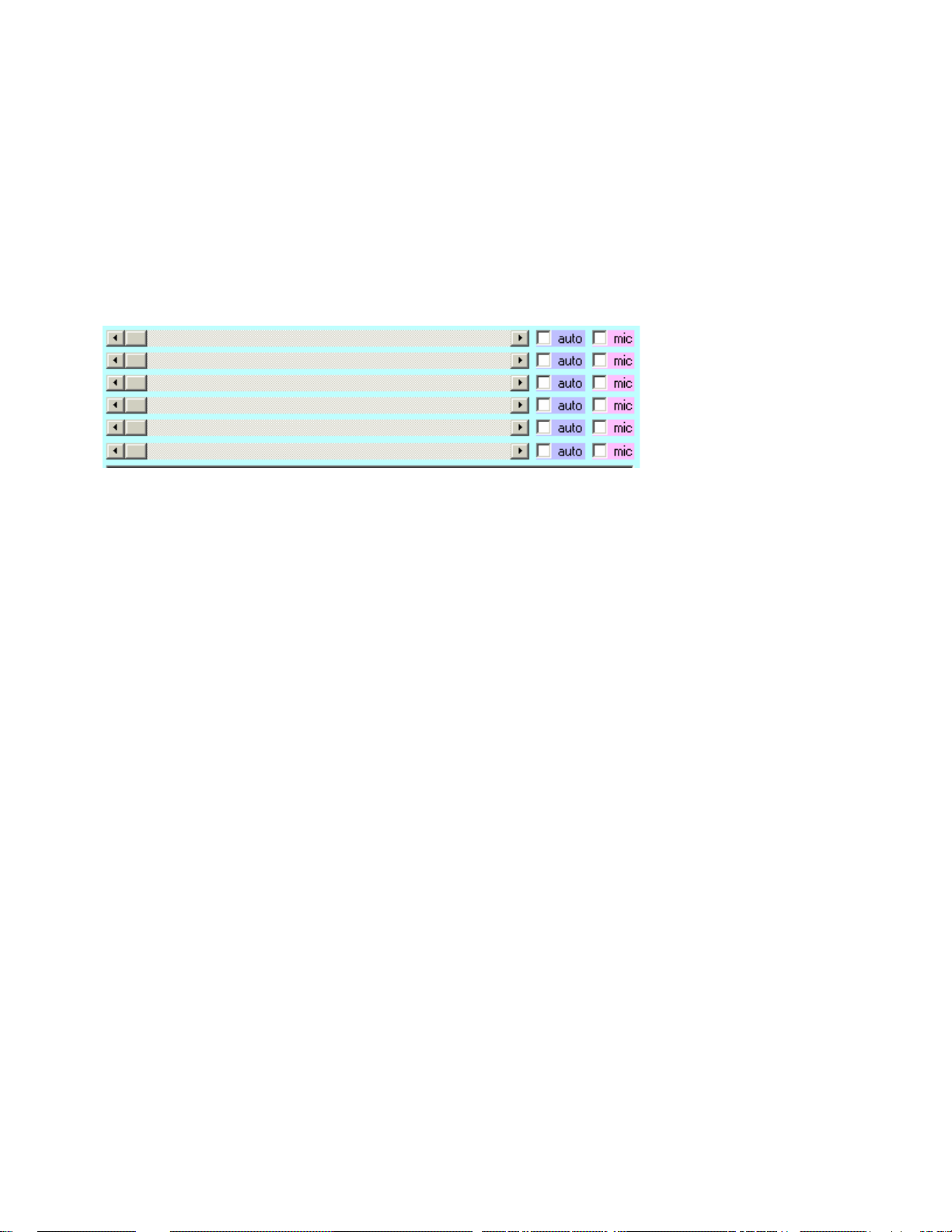
Horizontal Faders
The center is usually a set of 6 faders with labeled definitions to their left. These faders allow you to adjust
several variables that modify the laser presentation.
Each fader has an AUTO and MIC override.
When AUTO is enabled the fader is slowly ramped up and down for slow morp hs of that variable.
When MIC is enabled the fader is disabled and that variable is replaced by the audio input located on the
Laser Unit.
Below the faders is 4 Quick Text windows. Simply click on the text window and enter you own text. Then,
when ready, click SHOW TEXT to put that text on laser display. Click Text button in the help menu for more
detailed information.
Below the Text section are EDIT, SELECT# and FAST PAD.
The Edit button activates a simple graphics editor allowing you to design your own Custom graphics. Click
Editor button in the help menu for more detailed information.
The Select1 through Select8 buttons simply force the top fader to a fixed position that for those modes
where the top fader has only eight options.
Page 9
The Fast Pad button enables a small black window. When the mouse is inside this window, the 2nd and 3rd
faders are forced (fast) to a setting relative to the x/y coordinates inside the window.
The Bottom sections are Page and Record. Click on Pages button in the help menu for more detailed
information.
The very bottom has a blue bar for scripting a show. It basically allows you to record a series of mode
configurations and play them back in a timed sequence. Click Scripts button in the help menu for more
detailed information.
FADERS:
Faders have several active parts to them.
The End Tabs have a small arrow and, if mouse clicked, move the fader by one notch in the direction
indicated. If Mouse button is held down over these then the fader will creep quickly in the direction indicated.
The Center TAB element can be grabbed and dragged using the mouse button. Only when released does
the fader actually adopt the new value setting.
The Travel Bar can be mouse clicked to jump the fader in larger increments than the End Tabs.
Note: You may Mouse Click a fader and then use left & right arrows on your keyboard to change that fader.
PRESETS:
The select buttons 1 to 8 simply set fader #1 to 1 of 8 choices for those modes that have only 8 choices.
You may also set fader #1 AUTO active and the 8 available choices will be activated one at a time for a few
seconds each.
It is often easier to operate a system when the theory behind it has been detailed.
Scanning
The Display Unit has 3 scanning mirrors.
The first mirror is used for blanking (shutting the laser on and off) by re-directing the Laser beam away from
the next 2 mirrors.
The second mirror sweeps the beam up and down (only) on to the 3rd mirror.
The third mirror sweeps the beam from left to right (only) and out the front glass window.
Page 10

At any given moment, only a bright laser dot is actually projected. The apparent continuity or lines drawn are
due to persistence of vision. The darker the viewing area, the wider the pupils of your eyes can become
thus allowing more light to enter and increasing your persistence of vision.
Laser light, by nature, can imprint your eyes better than ordinary light allowing a much more vivid display.
A bright viewing area and/or slow moving laser beam will cause a flickering image to be perceived.
The Q-Scan has 4 basic operations:
1. First are patterns generated using math. You control the math function using one of the first 8 mode
buttons and the math variables using the 6 faders.
2. Second are graphical generators where faders may affect display speed or sound sensitivity.
3. Third is text generation that converts text to graphical output using an internal font embedded within
the display unit.
4. Fourth are animations and still pictures using vector graphics.
The user interface can be DMX-512 or this PC interface that uses RS232. This PC Interface allows full use
of all available features and the ability to custom design your own graphics.
The DMX-512 interface allows access to most display features and a simple text editor.
Custom Text and Graphics are uploaded to the Laser Unit from this program using the XFER commands.
The Laser Unit can store 8 text lines up to 80 characters each and 8 Custom graphics with up to 44 points
each.
DMX-512 is a standard used in the lighting industry to control stage lighting and other stage effects.
This PC program doesn't do any actual math, it is only used to plug numbers into the Laser Units memory
and to provide some simple controls.
The main advantage of this program is the custom graphics editor and rapid access to an almost unlimited
number of presets stored on your hard drive.
First, make sure the com port (Page 4) is set and communications validated.
Make certain Beam 10 is projecting on your Q-Beam or the appropriate beam that the Q-Scan is mounted
onto on another type of Beam Rail Projector.
Click on PAGE 1
Click on (optional)
Click on
(optional)
Click on
(optional)
If Laser Unit has warmed up for 30 seconds then you should see a laser circle. If you do not refer to section
in manual titled Alignment of Q-Scan to Beam Port.
VERY ****IMPORTANT**** NOTE:
Math modes are *NOT* visible if faders 5 or 6 (Chop Freq & Chop Duty) are zero.
Page 11

Note: Clicking any Brown Mode button automatically sends the ON and SYNC command.
(0) DMX Digital Value DMX Controller Fader 1
Generates patterns based on the circle.
A circle is created when 2 waves (sine) of identical height (amplitude) and speed (frequen cy) are mixed with
one of them given a 25% head start.
One wave is used to control left/right (X-axis) and the other wave is used for up/down (Y-axis).
The 1st fader controls the resulting circle's overall size.
The 2nd fader controls the speed of the first wave (X-frequency).
The 3rd fader controls the speed of the second wave (Y-frequency).
The 4th fader controls the head start percentage of the first wave (Phase).
The 5th fader controls the laser On/Off speed (Chop Frequency).
The 6th fader controls the laser On versus Off percentage (Chop Duty).
Page 12

Before using , click to see how the pattern will be saved.
Starting with a perfect circle, slow down one wave then put it back. You should notice that the circle is no
longer perfect. This is because the waves no longer have a 25% head start relationship. Click to
fix this.
Changing the Phase can offer a whole world of interesting patterns, but always remember to click
to see the true pattern.
The Phase value of 0 gives one wave a 25% head start for a perfect circle. The value 64 will add another
25% putting both axis in exact phase.
The Chop Frequency breaks the circle into a series of On/Off gaps. If the Chop frequency evenly divides the
circle frequency then the gaps will appear stationary, Otherwise the gaps will move around the circle.
The Chop Duty determines how much of each gap is Laser On and Laser Off by percentage.
Set Chop duty = 50% (value=128) then move chop frequency until stationary gaps appear. Then notice that
increasing the Duty fills in the gaps.
NOTE: The most common problem in not seeing the laser is that the Chop Freq=0 (t he beam is never
allowed on) or the Chop Duty=0 (the percentage of on time is zero)
(8) DMX Digital Value DMX Controller Fader 1
Generates patterns based on alias frequencies.
A circle is sampled at a frequency and the sampled points are connected with straight lines.
If a circle is sampled at 4 even intervals per circle then 4 points at 90 degrees each will produce a square.
The 1st fader controls the resulting image's overall size.
The 2nd fader controls the speed of the first sampler (X-frequency).
The 3rd fader controls the speed of the second sampler (Y-frequency).
The 4th fader controls the head start of the first sampler (Phase).
The 5th fader controls the laser On/Off speed (Chop Frequency).
The 6th fader controls the laser On versus Off percentage (Chop Duty).
Page 13

(16) DMX Digital Value DMX Controller Fader 1
Generates patterns based on circle A orbiting circle B.
A circle is drawn that moves around the perimeter of another circle.
The 1st fader controls the size relationship of circle A against circle B.
The 2nd fader controls the speed of the first circle (A-frequency).
The 3rd fader controls the speed of the second circle (B-frequency).
The 4th fader controls the head start of Circle A (Phase).
The 5th fader controls the laser On/Off speed (Chop Frequency).
The 6th fader controls the laser On versus Off percentage (Chop Duty).
(24) DMX Digital Value DMX Controller Fader 1
Generates a horizontal fan using a sine wave.
A sine wave is drawn where X-axis is a linear ramp and Y-axis is a sine wave.
The 1st fader controls the horizontal size (X Size).
The 2nd fader controls the vertical size amplitude (Y Size).
The 3rd fader controls the sine wave frequency (Y Freq).
The 4th fader controls the display Y-axis center (Y Center).
The 5th fader controls the laser On/Off speed (Chop Frequency).
The 6th fader controls the laser On versus Off percentage (Chop Duty).
Page 14

(32) DMX Digital Value DMX Controller Fader 1
Generates a horizontal fan using a linear ramp.
A horizontal line is drawn using a linear ramp with speed control and Y-axis positional step control and
vertical depth limits from the top.
The 1st fader controls the horizontal size (X Size).
The 2nd fader controls the horizontal sweep speed (X Freq).
The 3rd fader controls the vertical position step size (Y Step).
The 4th fader controls the vertical depth limit from top (Y Depth).
The 5th fader controls the laser On/Off speed (Chop Frequency).
The 6th fader controls the laser On versus Off percentage (Chop Duty).
(40) DMX Digital Value DMX Controller Fader 1
Generates a vertical fan using a linear ramp.
A vertical line is drawn using a linear ramp with speed control and X-axis positional step control and
horizontal width limits from the left.
The 1st fader controls the vertical size (Y Size).
The 2nd fader controls the vertical sweep speed (Y Freq).
The 3rd fader controls the horizontal position step size (X Step).
The 4th fader controls the horizontal width limit from left (X Width).
The 5th fader controls the laser On/Off speed (Chop Frequency).
The 6th fader controls the laser On versus Off percentage (Chop Duty).
Page 15

(48) DMX Digital Value DMX Controller Fader 1
Generates a horizontal in-line sequence of 16 beams.
A horizontal sequence of 16 beams is displayed with speed control and Y-axis positional step control and
vertical depth limits from the top.
The 1st fader controls the horizontal size (X Size).
The 2nd fader controls the horizontal sweep speed (X Freq).
The 3rd fader controls the vertical position step size (Y Step).
The 4th fader controls the vertical depth limit from top (Y Depth).
The 5th fader controls the minor x-axis offset (X Offset).
The 6th fader controls the binary beam mask (Beam Mask).
If fader 6 is set to zero then no beams will be shown and if set to max 255 then all beams are shown.
Using the calculator available in most Windows platforms, type the decimal value 170, then convert to binary
as 10101010. The 1's represent beam enables and the 0's are beam disables. Thus 170 enables every
other beam position.
The Binary pattern is repeated once on the left half and again on the right half for a total of 16 beams.
This feature allows specific mirrors to be targeted for various spray effects.
(56) DMX Digital Value DMX Controller Fader 1
Generates a horizontal random sequence of 16 beams.
A horizontal random sequence of 16 beams is displayed with speed control and Y-axis positional step
control and vertical depth limits from the top.
The 1st fader controls the horizontal size (X Size).
The 2nd fader controls the horizontal sweep speed (X Freq).
The 3rd fader controls the vertical position step size (Y Step).
The 4th fader controls the vertical depth limit from top (Y Depth).
The 5th fader controls the minor x-axis offset (X Offset).
Page 16

Mode 8 Continued
The 6th fader controls the binary beam mask (Beam Mask).
If fader 6 is set to zero then no beams will be shown and if set to max 255 then all beams are shown.
Using the calculator available in most windows platforms, type the decimal value 170, then convert to binary
as 10101010. The 1's represent beam enables and the 0's are beam disables. Thus 170 enables every
other beam position.
The Binary pattern is repeated once on the left half and again on the right half for a total of 16 beams.
This feature allows specific mirrors to be targeted for various spray effects.
(72) DMX Digital Value DMX Controller Fader 1
Generates 8 different beam patterns that are sound sensitive.
Use the Select1 through Select8 buttons to specify the beam pattern.
The 1st fader selects pattern 1 through 8 (Beams 1-8).
The 2nd fader controls the range of movement by sound volume (Range).
The 3rd fader controls the draw speed (Speed).
(104) DMX Digital Value DMX Controller Fader 1
Generates 8 different fan patterns that are sound sensitive.
Use the Select1 through Select8 buttons to specify the fan.
The 1st fader selects fan pattern 1 through 8 (Fans 1-8).
The 2nd fader controls the range of movement by sound volume (Range).
The 3rd fader controls the draw speed (Speed).
Page 17

(88) DMX Digital Value DMX Controller Fader 1
Generates 8 different tunnel patterns that are sound sensitive.
Use the Select1 through Select8 buttons to specify the tunnel.
The 1st fader selects pattern 1 through 8 (Tunnels 1-8).
The 2nd fader controls the range of movement by sound volume (Range).
The 3rd fader controls the draw speed (Speed).
(64) DMX Digital Value DMX Controller Fader 1
Generates 8 different graphical images that are sound sensitive.
Use the Select1 through Select8 buttons to specify the mobile graphic.
The 1st fader selects graphic 1 through 8 (Mobiles 1-8).
The 2nd fader controls the range of movement by sound volume (Range).
The 3rd fader controls the draw speed (Speed).
(80) DMX Digital Value DMX Controller Fader 1
Generates 8 different custom graphical images that are sound sensitive.
Custom graphics are created by you using the editor and transferred to laser's memory. See Editor section
for more details.
Use the Select1 through Select8 buttons to specify the custom mobile graphic.
The 1st fader selects custom graphic 1 through 8 (Custom 1-8).
The 2nd fader controls the range of movement by sound volume (Range).
The 3rd fader controls the draw speed (Speed).
Page 18

(96) DMX Digital Value DMX Controller Fader 1
Displays 1 of 8 preloaded text lines stored in the laser unit memory.
Use the Select1 through Select8 buttons to specify the text line.
The 1st fader selects text line 1 through 8 (Text 1-8).
See Text section for more details.
(112) DMX Digital Value DMX Controller Fader 1
8 different laser programs can be selected.
Use the Select1 through Select8 buttons to specify the laser program.
The 1st fader selects special 1 through 8 (Specials 1-8).
The 2nd fader controls vary with the active program (Control A).
The 3rd fader controls vary with the active program (Control B).
#1 is Fireworks, controls affect rocket speed and explode speed.
#2 is Random Rays, controls affect size and speed.
#3 is Splashes, controls affect splash size and speed.
#4 is GeoGraphs, controls affect geographs size and speed.
#5 is AutoBeams, controls affect vertical size limits and patterns.
#6 is Grid Morph, controls affect grid size and morph degree.
#7 is Laser Pong, controls affect left and right paddles. (for DMX users)
#8 is Laser Pointer, controls affect X & Y beam position. (use fast pad)
(120) DMX Digital Value DMX Controller Fader 1
Laser animation scenes and stills can be selected for laser display.
The 1st fader selects the group 1 through 8 (Group 1-8).
The 2nd fader selects the scene 0 through 255 (Scene 0-255).
Up to 2048 (8x256) individual animation scenes can be available.
Page 19

Scenes Section Continued
If the Q-Scan Expansion Set is not attached then the laser defaults to a selection of 1 animation and 7 stills
selected by the group fader 1-8.
See Scenes section and Expansion Set for more details.
There are 4 Text Buttons marked Show Text #. When mouse clicked, the text in the box to the immediate
right is displayed.
If the text has 8 letters or less then the display is stationary, otherwise the message is scrolled.
TEXT BOXES:
Click in a text box. Notice a cursor will appear. You may now Back-Space or Delete using the keyboard to
remove current text.
You can hold the mouse button down and sweep the text line, turning it all blue. Then hit Spacebar to erase
all the text in blue.
Note: Double quotes will be converted to single quotes for disk file structure purposes.
You may type in the text box and click the Show Text button on the left to laser display this text now.
You should place a few spaces before and after the visible text to allow for cleaner laser display if scrolling is
intended.
Only standard text, numbers and most symbols are supported. Lower case alphabet is converted to upp er
case by the laser.
Clicking Scene will restore the line to it's original setting. See Scenes section for more details.
Each preset (1-9) can hold 4 unique text lines for a total of 36 lines per file load.
Page 20

Functions
The Set Text button opens a small setting box with 6 labeled faders and 4 buttons.
Center: Allows you to place the text at different heights in the display area.
Speed: Controls the rate text is displayed, limited by hardware speeds.
Pre-Off: Controls the delay before laser is turned off to allow x,y settle.
Post-Off: Controls the delay before x,y movement to insure full laser off.
Pre-On: Controls the delay before laser is turned on to allow x,y settle.
Post-On: Controls the delay before x,y movement to insure full laser on.
Reverse: Sets the text display to reverse for rear screen projection.
Defaults: Presets faders to a factory standard setting.
Apply: Keeps these settings for laser initialization when re-started.
Cancel: Exit text setup without making any changes.
(Text Transfers):
The laser has allocated memory space to hold up to 8 text lines of 80 characters each.
This is for quick access using DMX-512 stage lighting equipment. This program can be u sed to quick load
the laser with the text desired.
Text Box 1 can be saved to laser text memory 1 or 2.
Text Box 2 can be saved to laser text memory 3 or 4.
Text Box 3 can be saved to laser text memory 5 or 6.
Text Box 4 can be saved to laser text memory 7 or 8.
Use Xfer Text button to see xfer choices. Use the same button to cancel the transfer.
Page 21

Typically, you type a sentence, click XferText button, select Xfer#1. Then erase that line and type a new line.
This time select Xfer#2.
The Helper window will show upload status. The upload takes a few seconds because the text must be
written to non-volatile memory.
The Text Mode button is used to browse or display the pre-loaded text lines.
You may click the Text Mode button and select the desired text line to display using Select 1 to 8 or fader
#1.
The cleanest use is to assign the Text Mode as a preset, that way the selected text line and the mode
change are acted upon at the same time.
Changing the selected line is put on hold until the current long scrolling line has completed.
The text mode can be scripted to add text to a show. See Scripting section for more details.
When this program is activated, a file called Preset.ini is loaded automatically. It is identical in format to the
samples.wad file.
A wad file contains all the information such as text, labels and fader settings for all the Mode buttons. With
16 modes and 9 presets, a total of 144 configurations is available from a single wad file.
THE PRESET PAGE and RECORD BUTTONS:
When one of the Record buttons is mouse clicked, the Current Mode and Fader settings are reco rded in
temporary memory with the current mode being set as the default for that particular record button used.
The 4 lines of text above is recorded under that record button also.
Before using a Record button, click the Sync button to see how the recorded presentation will appear when
restored later.
Page 22

Example: (Give it a Try)
Click the first Mode button, set the faders and click Record 1.
Click the next Mode button, set the faders and click Record 1 again.
Click the next Mode button, set the faders and click Record 1 again.
Now, click the first Mode button again and the faders are restored to your first set of settings.
Then, click the next Mode button and the faders are restored to your second set of settings.
Thus:
You may pre-define all 16 modes and faders under a single record button.
This procedure can be repeated for all 9 record buttons for a total of 144 unique settings and 36 unique lines
of text.
If you prefer a specific mode be the default for that record then click the desired mode again, see your
settings, and click the record one last time.
The "LAST" mode recorded under a record button becomes the default setting.
THE PAGE BUTTONS:
By clicking a Page button, all 16 modes and 4 lines of text become set, with the last recorded mode
becoming the current active setting (default).
You may go down the line of all the Pages 1-9 and see their defaults.
Also note that the last Page button clicked changes the Label color to identify the currently active preset.
THE PAGE NAME LABELS:
Above each Record button is a Label Window. This can be used 1 of 2 ways.
The Label can defined a category for all the modes under it such as GROUP#1, GROUP#2, etc.
Or; the label can be used to define a name you assign to the default, such as Flower, Spray, Fans, etc.
The Name Labels are changed by mouse clicking in the Label window, deleting the current text by DEL or
Back-Space and then re-typing a preferred label.
THE PAGE
BUTTON:
After setting all (or some) of the modes, capturing them and setting the Labels, you may click the Save
button.
A dialog box will open that allows you to save all of your settings to a single FILENAME.WAD file of your
choice.
You may replace an existing file or make a new one.
Be sure to use a file extension name of .WAD or don't type the extension name at all and the program will
assign the .wad extension automatically.
THE PAGE
BUTTON:
Click Load button to load a previously saved .wad file. The first 8 letters of this filename will appear in the
label window just below the Load button.
Page 23

At the Bottom of the screen you should be able to see a blue bar with some buttons on it. This is the Script
Editor and Control bar. To use or create scripts, the laser unit must be attached and functioning.
Scripting works nearly the same as the Record Buttons just above it, in the sense that you select the Mode
and adjust the Faders first, then click the Add Button to add (record) this configuration to the current script.
The Script can hold up to 255 records, where each configuration recorded is called a step.
The Fader, on the blue bar,
allows you to select and/or alter the period of time that each step is
allowed. It is in seconds with a minimum of 1 and a maximum of 255, thus allowing over 4 minutes (240
seconds) per step.
The
Button, when clicked, starts the script player at the current step and proceeds automatically
through all the following steps to the last one added. It then auto rewinds and repeats the process from step
1. During this sequence the
Button becomes the Pause button.
The
button allows you to advance deeper into the current script. It works at all times.
The
button is the same as the skip button except it backs up the script to the previous step.
Neither the
or buttons will auto-wrap the script, only the function can auto-
wrap (loop/repeat the sequence).
The
Button is used to add a new configuration to the script. It creates a new step and adds it after
the current step shown in the helper window. The step counter is then advanced to this newly added step.
The
Button is like the button, but instead of creating a new step, it simply replaces the
current step in the script with the mode & faders newly configured above.
The
Button is used to delete an unwanted step in the current script. The step that will be deleted
is displayed in the helper window and the configuration is visible from the settings above as well as the
display seen from the laser.
The
Button clears the current script for a fresh start and sets the seconds timer to the value of 10
seconds per step.
The
and Buttons allows you to load and save the script to disk as filename.srt script
files.
Page 24

The Show Text command buttons can NOT be scripted because they are not true modes. To add scripted
text to your show you must first upload the desired text to the laser display unit. This limits you to 8 lines of
text if scripting is used. Click Text butt
If short (non-scrolling) text lines are used then the script step timer will function as normal, otherwise, set the
timer to a maximum value for a scrolling text line and the script stepper will automatically step after the
whole line has been displayed o
If you wish some short simple words to appear automatically in a show then you might create the words
using the Mobile editor and store in the laser memory as custom graphics.
You may also pause the script player, click a text line manually, then continue running the player when
desired.
After a script is created you may use the
and buttons to select a specific step, then re-
adjust that steps time using the seconds fader. Be sure to save the script after any changes.
Mouse click
button to enable the Sound Graphics Editor. A second click will close the
editor.
Sound Graphics are simple line drawings with built-in sound activated motion.
Click Edit. Notice that a grid appears in the edit window when the mouse is inside the window. This is to help
determine edge and size relationships.
The helper window at the top will display the x,y coordinates of the mouse.
Click New Line button. Click 3 times in 3 different locations inside the edit window.
Page 25

Sound Graphics Editor Continued
The Graphic always starts in the center with the laser beam off. This is seen as a dull gray line to the first
visible point.
A green line represents a visible line in the final display.
Now click New Line button again. Click 3 more times insid e the edit window. Note that a new line has been
drawn with a dull gray line connecting the first and second.
Again, the dull gray line represents the travel path from the end of one line to the beginning of the next with
the laser off.
Next, click the small right arrow on the SELECT A POINT fader. Notice that the selected point in the edit
window is marked with a small circle.
Each point is numbered and the point number and it's x,y coordinate appear in the helper window ab ove.
You may also have noticed that 3 new buttons are enabled. Move Select a Point fader until point #1 is
selected.
Then click the Move Button. When the mouse is put back inside the edit window, the marked point will attach
itself to the mouse pointer.
Now move the point to a new location and mouse click again to anchor that point.
Page 26

Sound Graphics Editor Continued
This technique is how you rough draw the image desired, then select each point and move it to the desired
location if not already there.
Select the 1st point again. Now click Delete Point button. That point is deleted. This is how you remove
unwanted points.
To add a point to a line, select the nearest point that is part of that line. Then click STACK POINT.
This duplicates that point stacked on top of the original. Now click Move Point.
Move the new point to the desired position. This is how new points are added to a line.
Next, pick a point using Select a Point fader. Notice the motion is defined as still. This is because the motion
multiplier is set to 0.
Click the Multiply button. Each click selects greater motion up to 7. Also notice that as long as the Multiply is
not zero, then the direction select button to the left becomes defined.
As stated before, these graphics are sound sensitive. The sound input provides a raw value from 0 to 14. If
the multiplier is set to 1 and the direction is set to up, then, that point will move from it's current location to a
maximum of 14 units in the UP
If the multiplier is set to 7 then the maximum movement will be 7x14 or 98 in the given direction.
Clicking the Direction button left of the multiply button allows you to choose 1 of 8 possible directions.
Page 27

Sound Graphics Editor Continued
Every point in the graphic can be defined for direction and amount. This allows you to design Mobile
Graphics such as a Dancing Figure, etc.
Moving the Preview Motion fader will allow you to preview the motion. This fader replaces the raw sound
level value from 0 to 14.
Try to avoid points leaving the window edge.
Now click Clear Button to erase the edit window for a fresh start.
Click Add Beam button and click 3 different places on the edit window. Small red circles will appear. These
represent single points that can be used for dots or for beam effects in a fogged displ ay area.
Hint: keep the travel distances as short as possible to reduce flicker and keep the point count as low as
possible for the same reason.
Click the Save button to store this graphic on your hard drive as a Filename.Mob file.
Click the Load button to load the editor from a mobile file on the hard drive.
Finally, click the Transfer button to transfer this graphic to your laser's graphic memory.
There is memory space in the laser unit to store 8 custom mobile graphics.
Click Xfer 1-8 to select a memory position to occupy.
The Customs Mode button can then be used to see your creation in laser light with sound motion appli ed.
You may create any of several types of custom mobiles. They are:
1) A sound response Picture(s)
2) A sound response Fan(s)
3) A sound response Beam(s)
4) A sound response Tunnel(s)
Laser animation scenes and stills can be selected for laser display.
The 1st fader selects group 1 through 8 (Group 1-8).
The 2nd fader selects scene 0 through 255 (Scene 0-255).
Up to 2048 (8x256) individual animation scenes can be available.
If the Q-Scan Expansion Set is not attached then the laser defaults to a selection of 1 animation and 7 stills
selected by the group fader 1-8.
Page 28

With the Q-Scan Expansion Set:
If the memory module is attached then the selected group/scene will be played. It can be interrupted, mid
scene, to do another mode or start another scene. Scenes can be added to the script player.
If the script step time is less than the duration of the scene being played then the scene will be aborted and
the next step will be executed.
If the script step time is greater (IE: Maximum) then the script stepper will auto advance after the scene has
been played.
Without the Expansion Set:
If you have attached a standard 25-pin parallel cable from your PC to the laser and your printer port is
standard LPT1 then you may RIGHT MOUSE click on the
button.
A file select window will open and allow you to specify a FILENAME.BIN animation file to be played.
To avoid the printer drivers supported by Windows, the selected .BIN file is copied directly to the LPT1 port
printer spooler.
The animation will play just once and then the laser unit will shut off.
If you simply attempt to click the ON button and no data is spooled then the unit will play the default
animation or still of the group selected.
If you interrupt the animation from the LPT1 source then the spool is emptied before another is allowed to
begin.
Please allow this type of animation to play itself out before starting another or else the results may be
unpredictable.
The Red LED on the back of the Q-Scan will be off during animations and comes on again when the spool is
empty.
This special animation play mode can not be scripted.
The parallel cable should be less than 25 feet long for best results.
More Lightspeed animations will be made available from OmniSistem Lights and Effects. Stay tuned to
www.omnisistem.com
for the latest support and accessories for the Q-Scan PC/DMX.
To create your own animations simply purchase the Mynx Lyte program from OmniSistem. It is a simple
vector editor for creating custom stills and animations in Hi-Res (.2DV) and Lo-Res (.BIN) formats. Or you
can purchase Mynx Lyte with Trace-It software.
Page 29

QSCAN DMX SPECIFICS FOR ALL 8 CHANNELS VS MODES:
Modes Base Base +1 Base +2 Base +3 Base +4 Base +5 Base +6 Base +7
Circle Patterns 0>7 XYSize Freq-A Freq-B Phase Chop Duty Mic
Line Patterns 8>15 XYSize Freq-A Freq-B Phase Chop Duty Mic
Spiral Patterns 16>23 ABsize Freq-A Freq-B Phase Chop Duty Mic
Waves Horizontal 24>31 Xsize Ysize Yfreq Center Chop Duty Mic
Fan Horizontal 32>39 Xsize Xfreq Ystep Ydepth Chop Duty Mic
Fan Vertical 40>47 Ysize Yfreq Xstep Xwidth Chop Duty Mic
Beams Series 48>55 Xsize Xfreq Ystep Ydepth Offset Mask Mic
Beams Random 56>63 Xsize Xfreq Ystep Ydepth Offset Mask Mic
Sound Graphics 64>71 #1=>#8 Sense Speed Mic
Sound Beams 72>79 #1=>#8 Sense Speed Mic
Custom 80>87 #1=>#8 Sense Speed Mic
Sound Tunnels 88>95 #1=>#8 Sense Speed Mic
Stored Text 96>103 #1=>#8 Mic
Sound Fans 104>111 #1=>#8 Sense Speed Mic
Specials 112>119 #1=>#8 Def-A Def-B Mic
Scenes 120>127 #1=>#8 Scene Speed OffBlnk OnBlnk Mic
Text Line 1 128>135
Text Line 2 136>143
Text Line 3 144>151
Text Line 4 152>159
Text Line 5 160>167
Text Line 6 168>175
Text Line 7 176>183
Text Line 8 184>191
Edit Line 1 192>199 Chr Pos Letter
Edit Line 2 200>207 Chr Pos Letter
Edit Line 3 208>215 Chr Pos Letter
Edit Line 4 216>223 Chr Pos Letter
Edit Line 5 224>231 Chr Pos Letter
Edit Line 6 232>239 Chr Pos Letter
Edit Line 7 240>247 Chr Pos Letter
Edit Line 8 248>255 Chr Pos Letter
Note: Where the mode has only 8 options such as the Mobile Graphics then
set base+1 selection as:
Option 1=0>31
Option 2=32>63
Option 3=64>95
Option 4=96>127
Option 5=128>159
Option 6=160>191
Option 7=192>223
Page 30

QSCAN DMX SPECIFICS FOR ALL 8 CHANNELS VS MODES: (Ctn’d)
Option 8=224>255
Where ">" means "through" above.
Note: Animations require major system resources, so if the DMX is used to
activate an animation then the DMX data stream is ignored until the animation
plays itself out.
Sound control is important for sound dynamic presentations.
Note: Base+7 is sound override of channels 1 through 6. If set to zero then
no sound controls are enabled except modes specifically soun d oriented.
If set to 255 then the sound will override all the DMX channels 1-6.
Selective application of sound override of DMX channels can be mixed in all
possible combinations using the following procedure:
Start with the value 0.
If sound is to control channel 1 (base+1) then add 4 to your number.
If sound is to control channel 2 (base+2) then add 8 to your number.
If sound is to control channel 3 (base+3) then add 16 to your number.
If sound is to control channel 4 (base+4) then add 32 to your number.
If sound is to control channel 5 (base+5) then add 64 to your number.
If sound is to control channel 6 (base+6) then add 128 to your number.
Now set dmx channel 7 (base+7) to the value calculated.
Usually the modes are activated as a sudden preset where all the values are presented within a short time
limit. Slower modifications may require sync. If you are exploring math patterns then you should jog the MIC
control (base+7) up and down quickly to re-sync the pattern. This should be done before saving a pattern as
a preset to visually see what you are about to save as a preset.
To set a DMX address, follow this procedure:
1. Determine your base address. If running a Q-Scan on a Q-Beam your base address should be 12
channels higher than the start address of your Q-Beam. (Example) If your Q-Beam has a start
address of 1 then the Q-Scan should be Base address 13 as the Q-Beam requires 12 channels.
This however will change if the controller you are using groups control channels in ban ks of 8 or 16.
It may be more convenient to address the Q-Scan on the next bank of faders after the Q-Beam.
2. Set the next fixture in the series of fixtures 9 addresses away from the base address of the Q-Scan
as not to cause address conflicts.
Use the table on the next page to determine the dipswitch settings for your base address:
Page 31

Each Q-Scan PC comes with a special adapter called a SIKA cable. This cable must be placed between the
Q-Scan and the computer. You may extend this cable with a standard 9 Pin to 9 Pin Male to Female cable
found at most stores where computers are sold. DO NOT EVER connect the Q-Scan to your PC without the
SIKA cable as serious damage to your PC can occur.
For those who would like to make their own cable we have provided this ca bling guide.
THE CUSTOM SIKA CABLE SHOULD BE WIRED AS FOLLOWS:
IBM 9 PIN female QSCAN MALE 9 pin
2..RECEIVE---<-----red----------<---------XMIT 3
3..SEND------>--------yel------->---------REC 2
5..COMMON----><----------wht----><--------GND 5
4..\ +12 6 KEYPAD POWER
6.. \ TIE TOGETHER (NULL MODEM) -12 7 KEYPAD POWER
7.. /
8../
Page 32

IBM 25 PIN female QSCAN MALE 9 pin
3..RECEIVE---<----red-----------<---------XMIT 3
2..SEND------>-------yel-------->---------REC 2
7..COMMON----><---------wht-----><--------GND 5
4..\ +12 6 KEYPAD POWER
5.. \ TIE TOGETHER (NULL MODEM) -12 7 KEYPAD POWER
6.. /
20./
THE PARALLEL CABLE IS A STANDARD 25 PIN STRAIGHT THROUGH MALE/MALE D-SUB.
MOUNTING
The mounting of the Q-Scan onto the Q-Beam will require the following parts provided with your Q-Scan and
comes inside the Q-Scan packaging: 4,5,6
Yoke extenders are necessary to provide clearance for the Q-Scan head for installations using the yoke in
the top mount position.
ALIGNMENT
Precise alignment of the port 10 that will project the beam into the Q-Scan has to be done prior to use. An
alignment tool has been provided to make this process simple. Follow the steps below to align the Q-Beam
to the Q-Scan.
• Step one – Remove the beam modules on ports 8,9,10
• Step two – Press Enter on the Back of the Q-Beam
• Step Three – Press Test Align on the Back of the Q-Beam
• Step Four – Press Up until the beam comes out of Port 10
• Step Five – Place Q-Scan Adjustment Tube in the module clamp of port 10 and tighten to finger tight
• Step Six – Remove the two black caps on the opposite side of the top rail of the Q-Beam. (Not the
two on the end of the projector). These are for the Red adjustment. The right ones is near the Red
LED on the top rail.
• Step Seven – Using a flat head screw driver adjust the beam so that it hits the exact center of the
centering mark on the top of the Q-Scan Alignment Tool as Illustrated below.
• Step Eight – Remove alignment tool.
• Step Nine – Place the Q-Scan into module ports 10 and 8 and tighten.
Page 33

• Step Ten –Go to beginning of the manual and begin the learning and set up of the system.
Illustration of proper alignment
Proceed to Section 1.0
1. Follow Instructions
All set-up and operating instructions should be followed for the safe operation of your scanning system.
2. Power Source
Operate this system only with the type of power supply listed on the products AC input. Never by-pass
grounding plugs as these have been provided for safety.
3. Objects and Liquids
Do not push objects into the unit through any openings as they may touch dangerous voltages, which may
result in fire or electrical shock. Do not spill liquids of any kind into the unit.
Page 34

4. Servicing
Do not attempt to service this system yourself as opening the unit can expose you to dangerous voltage.
Qualified OmniSistem technicians should perform Service only. Opening or removing the cover will void the
warranty.
5. Damage Requiring Service
• Immediately unplug the unit from the receptacle.
• Any damage requiring service as stated above must be reported immediately to
OmniSistem Lights and Effects and an RMA# will be issued.
• The product must be returned in its original packaging.
• Return the unit with ALL components and cables.
• Any damage that occurs do to inappropriate packaging will be repaired at your expense.
6. Laser Safety
Laser can pose an extreme hazard to the eyes and skin!
• NEVER expose eyes by looking directly into the beam no matter what the output level.
• NEVER uses eyes to align the beam by looking directly into the aperture.
• AVOID direct or collateral radiation from the laser.
• NEVER point the aperture of this product in a way that the audience can be exposed to direct or
indirect laser light.
• MAKE sure that all warning labels and product labels remain attached and in there proper place.
There are regulations that must be followed and adhered to when operating a laser system abov e
1mW.
ClassIIIa 1mw to 4.95mW
All laser radiation must remain 2.5 meters vertically above the floor.
ClassIIIb 5mW to 499mW to ClassIV >500mW
• All Laser Radiation must remain 3.0 meters vertically above the floor and 2.5 meters horizontally
away from human contact. This 2.5-meter rule applies to catwalks, balconies or other raised
surfaces.
• If the system is stand-alone with no operator present double the distances as stated above.
• In the event of a bounce mirror shift, beam turret failure, accidental exposure, scanner failure, or
other anomalous event that falls short of the CDRH guidelines IMMEDIATELY SHUT DOWN YOUR
LASER SYSTEM and do not operate it again until the problem has been remedied.
• Comply with all conditions of your variance. (Variance Regulated Products Only)
• Insure all beams and effects are terminated safely.
• Remember Safety should be your first priority.
Page 35

 Loading...