

Page 1

StarBrite
StarBrite Controller
PR-8710
PR-8710C
This product manual contains important information about the safe installation and use of this
product. Please read and follow these instructions carefully and keep this manual in a safe place
for future reference.
PR LIGHTING LTD.
http://www.pr-lighting.com
Page 2
INDEX
SAFE USAGE OF THE PRODUCT 3
INST ALLING THE PRODUCT 4
POWER SUPPLY – MAINS 4
CONTROL CONNECTIONS 4
DMX TERMINA TOR 6
SETUP OPTIONS-PRODUCT CONFIGURA TION 6
OPERA TION MENU 7
TO SET THE DMX START ADDRESS 8
DMX PROTOCOL 9
LED INDICATION 11
MAINTENANCE 11
TROUBLESHOOTING 11
TECHNICAL DA TA 12
ELECTRICAL DIAGRAM 13
COMPONENT ORDER CODES 14
Please note that as part of our ongoing commitment to continuous product development, specifications are subject to change without
notice. Whilst every care is taken in the preparation of this manual we reserve the right to change specifications in the course of
product improvement. The publishers cannot be held responsible for the accuracy of the information herein, or any consequence
arising from them.
Every unit is tested completely and packed properly by the manufacturer. Please make sure the packing and / or the unit are in good
condition before installation and use. Should there be any damage caused by transportation, consult your dealer and do not use the
unit. Any damage caused by improper use will not be assumed by the manufacturer and / or dealer.
ACCESSORIES
These items are packed toge ther with the project or:
Name Quantity Unit Remark
Power-cord 1 Pc
3-pin XLR cable 1 Pc With plug
5-pin signal connection cable 1 Pc With plug
This manual 1 Pc
2/16
Page 3

SAFE USAGE OF THE PRODUCT
When unpacking and before disposing of the carton, check there is no transportation damage before using the product.
Should there be any damage caused by transportation, consult your dealer and do not use the apparatus.
The product is for indoor and outdoor use, but not a llowed to be used outdoor in rain y days. Use only in dry loca tions.
Keep this product away from rain and moisture, excessive heat, humidity and dus t. Do not allow contact with water or
any other liquids.
The product is not designed or intended to be mounted directly onto inflammable surfaces.
The working environment temperature of the product is 0℃~40℃.
The product is only intended for installation, operation and maintenance by qualified personnel according to the manual.
Don’t open the product for maintenance by yourself and don’t attempt to dismantle and/or modify the product in any way.
When the LED StarBrite Controller is installed, please make sure the ventilation slots of the controller ar e not blocked.
If the fuse is damaged, use one of the same specification to replace it, and befor e doing repair work, make sure the
power is cut off.
Do not connect this device to any other types of dim mer apparatu s.
Do not look at lighted LEDs from a distance of less than 40cm. Watching lighted LEDs from a short distance for a long
time is bad for your eyes.
Before installation, ensure that the voltage and frequency of power supply match the power requirements of the product.
Make sure that the power-cord is never crimpe d or damaged by sharp edges. Never let the power-cord come into contact
wi t h o t h e r c a b l e s . Only handle the power-cord by the plug. Never pull out the plug by tugging the power-cord.
The product should be earthed by power plugs with three-pin, forbid using two-pin plugs in case of electrical shock.
If the LED StarBrite Controller is mounted onto a high place, besides using screws to fix it, for safety purpose, a proved
safety cord is used as a secondary safety fixing, and it should be attached as shown in the “installing the product” section
of this manual.
There is no user serviceable parts inside the product, before operating this product, please check all the housing of the
LED StarBrite Controller and the driving device is installed, and the screws are fixed in place. Do not open the housing
and never operate the product with the covers removed.
If the LED StarBrite Controller is put on a table, make sure the table is stable and fix the controller on the center of the
table. Do not put the controller on the fringe of the table in case of falling.
To preserve the environment, the product should be recycled at the end of its life according to the arrangement of related
department.
If you have any questions, don’t hesitate to consult your dealer or manufacturer.
Always disconnect from the mains, w hen the device is not in use or before cleaning it or
before attempting any main tenance work !
3/16
Page 4
INST ALL THE PRODUCT
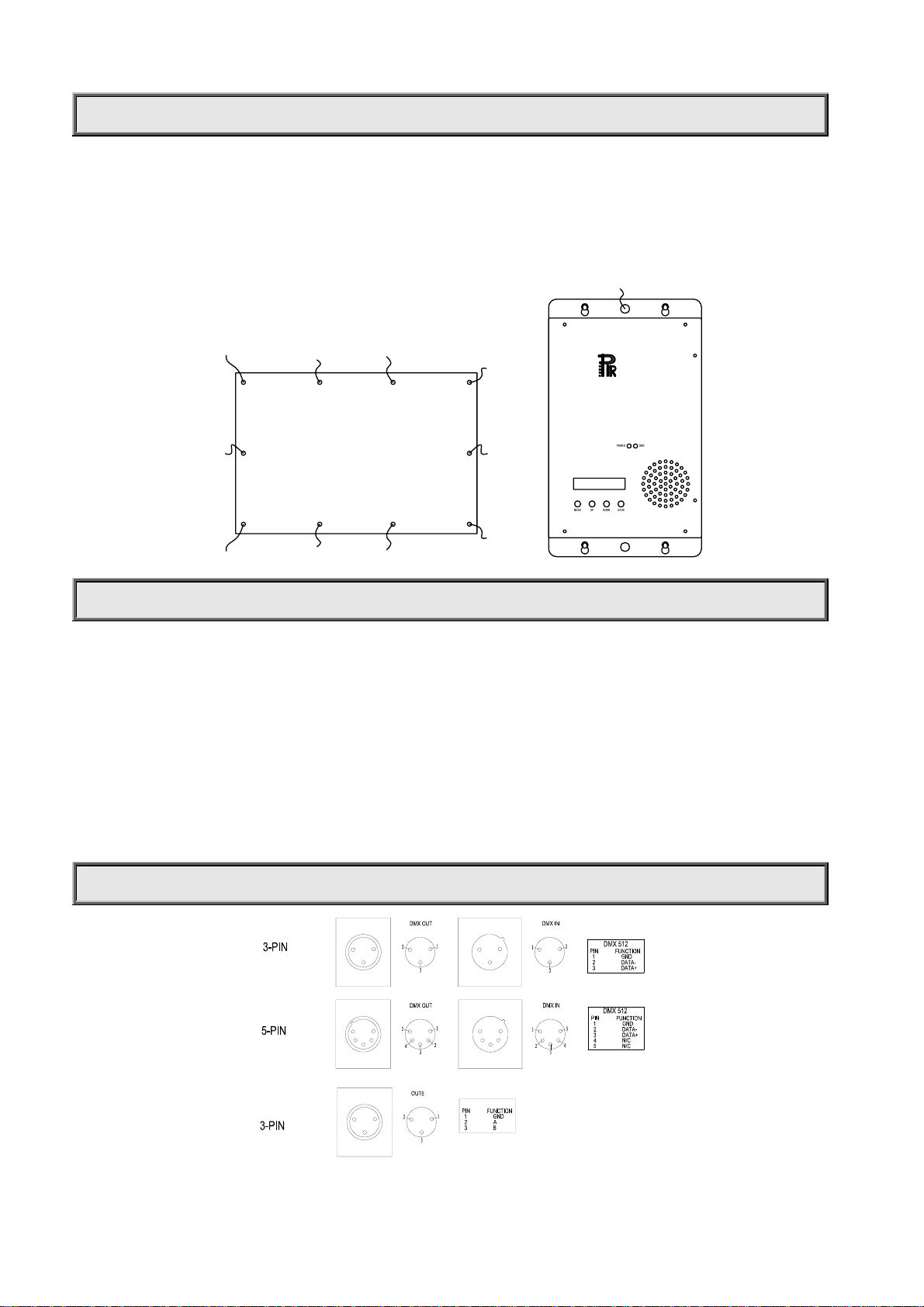
When a LED StarBrite is used, it should be installed as the figure below on the left. Thrill through the eyelets on four
fringes of the LED StarBrite by ropes and hang it at a higher place to achieve the effect of clusters of stars covering the
sky.
Generally , LED StarBrite Controller can be put on a
flat surface, such as a table, or a floor, but if you want to mount it
on a higher place, fix both the top and bottom fringes of th e controller by four screws into the four screw e ye lets, and
use a proved safety cord through the hole prearranged in the midd le of the top fringe as a secondary safe ty fixing at
the same time. The figure below on the right shows all of this.
PR-8710C
StarBrite Controller
POWERDM
X
LED StarBrite
MENUUPDOWNSAV
E
POWER SUPPLY-MAINS
Connect the power cord as follows:
L (live) =brown
E (earth) =yellow/green
N (neutral) =blue
Use the plug provided to connect the mains power to the LED StarBrite Controller paying attention to the voltage and
frequency marked on the panel of the LED StarBrite Controller . It is recommended that each LED S tarBrite Controller be
supplied separately so that they may be individually switched on and off.
IMPORT ANT
It is essential that each LED StarBrite Controller is correctly earthed and the elect rical ins tallation conforms t o
all relevant standa rds.
CONTROL CONNECTIONS
4/16
Page 5
Connection between a LED StarBrite and a LED StarBrite Controller must be made with a special 5-pin signal
connection cable with a length of 15 meters (connect any one of the OUT1~OUT4 to the 5-pin input port of the LED
StarBrite driver box). And between the LED StarBrite Controllers or between the LED StarBrite Controller and the
console, 3-pin XLR cables are used for co nnection (co nnect by DMX IN / DMX OU T port). In addition , 3- PIN socke t of
the OUT5 port only provides signal output (without power supply), it applies for Master/Slave mode only .
The 5-pin signal connection cable and the 3-pin XLR cable are connected as shown in the figure above.
Note: care should be taken to ensure that none of the pins touch the metallic body of the plug or each other. The body of
the plug is not connected in any way. The product accepts digital control signals in protocol DMX512 (1990).
First of all, connect a LED StarBrite Controller and a LED StarBrite, and it can run in the stand-alone mode with 12 preset
programs, according to the different applications, the Master/Slave mode and the DMX control mode can be selected.
In the Master/Slave mode, the master LED StarBrite Controller and the slave StarBrite Controller must be connected by
a 3-pin XLR cable from the master LED St arBrite Controller’s OUT5 port to the first slave LED StarBrite Controller’s DMX
IN port, then from the first slave LED StarBrite Controller’s OUT5 port to the second slave LED StarBrite Controller’s
DMX IN port, and so on, until all the LED StarBrite Controllers are connected. Eventually set the menu of all the slave
LED StarBrite Controllers to the “Slave” mode. At this time, Master/Slave mode is in effect.
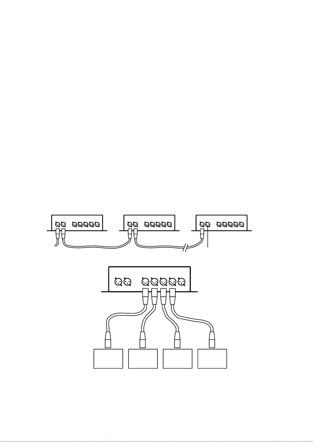
In the DMX control mode, connections among the console and several LED StarBrite Controllers are similar with the
control mode above. Use a 3-pin XLR cable to connect the DMX output port of the console to the first LED StarBrite
Controller’s DMX IN port, then from the first LED StarBrite Controller’s DMX OUT port to the second LED StarBrite
Controller’s DMX IN port, and so on , until all the LED StarBrite Controllers are connected, Eventua lly, connect the LED
StarBrite Controller’s DMX OUT port to a DMX terminator (The address of any LED StarBrite Controller should be
correctly configured, for details, see t he following sections).
To make the DMX control mode valid, set the menu of the LED StarBrite Controller to the DMX CHANNEL .When the
yellow indicator on the panel o f the LED S tarBrite Contro ller is on, DMX signal is OK.
Connections among the console and several LED StarBrite Controllers are shown in the figure below .
DMX IN DMX OUT OUT1 OUT2 OUT3 OUT4 OUT5 DMX IN DMX OUT OUT1 OUT2 OUT3 OUT4 OUT5 DMX IN DMX OUT OUT1 OUT2 OUT3 OUT4 OUT5
TO THE CONSOLE
DMX IN DMX OUT OUT1 OUT2 OUT3 OUT4 OUT5
LED StarBrite
LED StarBrite
LED StarBrite
TERMINATER
LED StarBrite
5/16
Page 6

DMX TERMINA T OR
In the DMX control mode, for the last LE D S t arB rite Contro ller in the chai n, the DMX OUT port has to be connected wit h
a DMX terminator. This prevents electrical noise from disturbing and corrupting the DMX control signals.
The DMX terminator is simply an XLR connec tor with a 120Ω (ohm) resistor connected across pins 2 and 3 , which is
then plugged into the output socke t on the last LED StarBrite Controller in the chain. The connections are illustrated
below.
2
120
1
3
DMX TERMINATOR
CONNECTION
Connect a 120 (OHM) resistor
across pins 2 and 3 in an XLR plug
and insert into the DMX out socket
on the last unit in the chain.
PIN 2
PIN 3
SETUP OPTIONS-PRODUCT CONFIGURATION
UP
As the figure above, product configuration can be set conveniently via push-bu tton switch and LCD display. Turn the
StarBrite Controller on and the LCD display will show the product model and software version as “PR-8710C VER:XXX”.
T o browse through various Setup Options, Press button ENTER for 5 seconds to unlock the panel if it is locked. Then the
LCD display will show the function menus, 15 menus in total, and each menu has its specific function.
Press button
indicate “saving****”. After that, a sign “*” will be appeared at the top right corner of that menu and the LCD
display will first show the settings next time when the controller is turned on.
Press button UP or DOWN to change the speed, colour or address in the menu (increase or decrease the
numerical value).
If you stay for one minute without any operation, the panel will be locked automatically, and then “PR Lighting” and
“StarBrite” will be showed by turns in the LCD display .
FUNC to change the menu, press button ENTER to save your settings an d a t th i s t im e t h e LC D w i ll
6/16
Page 7

OPERA T ION MENU
Menu
PROGRAM 1 Speed[XX] Save
PROGRAM 2 Speed[XX] Save
PROGRAM 3 Speed[XX] Save
PROGRAM 4 Speed[XX] Save
PROGRAM 5 Speed[XX] Save
PROGRAM 6 Speed[XX] Save
PROGRAM 7 Speed[XX] Save
PROGRAM 8 Speed[XX] Save
PROGRAM 9 Speed[XX] Save
PROGRAM 10 Speed[XX] Save
PROGRAM 1 1 Speed[XX] Save
AUTO RUN Save Stand-alone mode
range of XX :1~16
Description
Single Color Color[XX] Save Single colour mode, used for testing, range of XX :1~7
The address is [XX] Save Set the address of the controller , range of XX: 1~20
26 DMX CHANNEL Save DMX control mode
Slave Save Slave mode
7/16
Page 8

TO SET THE DMX START ADDRESS
When a console is used to control several LED StarBrite Controllers, so that to control more LED StarBrites, each LED
StarBrite Controller must be given a DMX start address so that the correct L ED StarBrite Controller responds to the
correct control signals. This DMX start address is the channel number from which the LED StarBrite Controller starts to
“listen” to the digital control information being sent out from the console. The product has 26 channels, so set the No. 1
LED StarBrite Controller’s address 001, No. 2 LED StarBrite Controller’s address 027, No. 3 LED StarBrite Controller’s
address 053, No. 4 LED StarBrite Controller’s address 079, and so on.
Turn on the LED StarBrite Controller, you can find the address menu by pressing button FUNC , Then follow the
configuration described in the“ SETUP OPTIONS-PRODUCT CONFIGURA TION” section.
8/16
Page 9

DMX PROTOCOL
CHANNEL FUNCTION DMX DESCRIPTION
1 Red
2 Green
3 Blue
4 Red
5 Green
6 Blue
7 Red
8 Green
9 Blue
10 Red
11 Green
12 Blue
13 Red
14 Green
15 Blue
16 Red
17 Green
18 Blue
19 Red
20 Green 000-240 Dimming, from dark to light
000-240 Dimming, from dark to light
241-255 Strobe, from slow to fast
000-240 Dimming, from dark to light
241-255 Strobe, from slow to fast
000-240 Dimming, from dark to light
241-255 Strobe, from slow to fast
000-240 Dimming, from dark to light
241-255 Strobe, from slow to fast
000-240 Dimming, from dark to light
241-255 Strobe, from slow to fast
000-240 Dimming, from dark to light
241-255 Strobe, from slow to fast
000-240 Dimming, from dark to light
241-255 Strobe, from slow to fast
000-240 Dimming, from dark to light
241-255 Strobe, from slow to fast
000-240 Dimming, from dark to light
241-255 Strobe, from slow to fast
000-240 Dimming, from dark to light
241-255 Strobe, from slow to fast
000-240 Dimming, from dark to light
241-255 Strobe, from slow to fast
000-240 Dimming, from dark to light
241-255 Strobe, from slow to fast
000-240 Dimming, from dark to light
241-255 Strobe, from slow to fast
000-240 Dimming, from dark to light
241-255 Strobe, from slow to fast
000-240 Dimming, from dark to light
241-255 Strobe, from slow to fast
000-240 Dimming, from dark to light
241-255 Strobe, from slow to fast
000-240 Dimming, from dark to light
241-255 Strobe, from slow to fast
000-240 Dimming, from dark to light
241-255 Strobe, from slow to fast
000-240 Dimming, from dark to light
241-255 Strobe, from slow to fast
9/16
Page 10

21 Blue
22 Red
23 Green
24 Blue
25 White
26 Preset Programs
241-255 Strobe, from slow to fast
000-240 Dimming, from dark to light
241-255 Strobe, from slow to fast
000-240 Dimming, from dark to light
241-255 Strobe, from slow to fast
000-240 Dimming, from dark to light
241-255 Strobe, from slow to fast
000-240 Dimming, from dark to light
241-255 Strobe, from slow to fast
000 Invalid
001-240 Dimming, from dark to light
241-255 Strobe, from slow to fast
000-063 Invalid
064-079 Preset programs 1
080-095 Preset programs 2
096-111 Preset programs 3
112-127 Preset programs 4
128-143 Preset programs 5
144-159 Preset programs 6
160-175 Preset programs 7
176-191 Preset programs 8
192-207 Preset programs 9
208-223 Preset programs 10
224-239 Preset programs 11
240-255 Preset programs 12
10/16
Page 11

LED INDICATION
Green
Y ellow
On Power on
Off Power off
On
Off
DMX signal OK
No DMX signal
MAINTENANCE
When a LED StarBrite is used or stored for a long time , dust and dirt will accumulate on its surface. To maintain an
optimum light output, prolong the product’s life and ensure its reliability, it is very important to carry out the maintenance
work.
Pay attention to the LED StarBrite’s cleanness every day. When lot s of dust and dirt accumulates on the LED StarBrite,
flap or wobble the StarBrite in order to remove the accumulation. It is advised to clean the LED StarBrite once every three
months.
When the LED StarBrite Controller do not work, check the fuse on the power s ocket of the LED StarBrite Controller.
Once damaged, it should be replace d by fuses of the same specificat ion only .
Any maintenance work s hould only be carried out by qualified tec hnicians.
TROUBLESHOOTING
PROBLEM ACTION
The LED StarBrite Controller doesn’t switch on. ¾ Check the fuse on the power socket.
The LED StarBrite doesn’t respond to the
console.
The LED StarBrite can work normally , but
doesn’t respond to the LED StarBrite Controller.
¾ Make sure the yellow indicator on th e panel is on, and the
DMX signal is OK.
¾ Make sure the DMX address is correctly configured.
¾ Make sure the 5-pin signal connection cable is correctly
connected.
11/16
Page 12

TECHNICAL DAT A
VOLTAGES:
LED St arBrite Control ler :
LED StarBrite : 10V~15V DC
POWER CONSUMPTION:
LED St arBrite Control ler :
LED StarBrite : Less than 30W
BRIGHTNESS OF LED STARBRITE:
More than 150cd when all the LEDs emit white light
WORK ENVIRONMENT TEMPERATURE:
0℃~40℃
IP PROTECTION:
IPX3
LIFE:
30000 hours
NET WEIGHT:
LED StarBrite(15-meter signal connection cable included):
LED St arBrite Control ler :
SIZES:
See it below
85V~132V/170V~264V AC,50/60Hz
Input: 200W, Output:150W(Max)(It can drive four pcs of LED StarBrite)
20kg
2.3kg.
LED StarBrite
12/16
PR-8710C
StarBrite Controller
POWERDM
MENUUPDOWNSAV
E
X
OUT OUT1 OUT2 OUT3 OUT4 OUT5
IN DMX
DMX
Page 13

Page 14

COMPONENT ORDER CODES
NAME PART NO. QUANTITY REMARK
POWER SOCKET 210020012 1 PST-101 10A/250V
POWER SWITCH 190010009 1 Red ,with indicator
POWER SUPPLY 192010133 1
5-PIN SIGNAL
CONNECTION SOCKET
CONTROL PCB OF
LED STAR TBRITE CONTROLLER
CONTROL PCB OF
LED STARTBRITE
LED MOUNTING PCB OF LED
STARTBRITE
212020059 1 YS1465-J5F2C
230060052 1
230060054 1
230060051 144
Input:AC85~132V/AC170~264V
Output:DC15V,15A
14/16
Page 15

15/16
Page 16

PR LIGHTING L TD.
PR New Hi-tech Science Park, 1582 Xingye Avenue
Nancun Panyu, Guangzhou, 511442 China
TEL: +86-20-3995 2888
FAX: +86-20- 3995 2330
P/N: 320050002
Preliminary Revision: 20090220
16/16
 Loading...