

Page 1
Introduction
Thank you for purchasing Magic Box II. Magic Box II is a 2 channel DMX laser can
be controlled via a standard DMX controller. It is a light weight, mini intel ligent fixture
and is an ideal product for discos, clubs, exhibitions and any place that need visionary
effect. For safe operation, read this manual before powering or installing the fixture,
follow the safety precautions listed below, and observe all warnings printed in this
manual and on the fixture.
Safety Precautions
Do not spill liquids in to or on to your unit. If this ever happens, disco nnect the
main power immediately. Do not connect this unit to any dimmer pack.
Always disconnect from main power before making any type of connection.
Be sure to locate this unit in a place with adequate ventilation at least 15 cm from a
wall, and mount this unit in safe and stable matter.
To prevent fire or shock hazard, do not expose this unit to a high temperature or
high humidity area. Please unplug unit when not in use.
Always keep combustible materials away from the fixture.
Class 3B laser should be mounted at or above 3 meters height. Project Class 3B
laser light above eye level. Do not project Class 3B Laser light on specular material.
The entrance to area where Class3B laser is used should be posted with
appropriate warning signs.
This unit is intended for indoor use. Use of this unit outdoors voids all warranties.
Always refer service to a qualified technician. Never look directl y into las er beam.
Occasional breaks are necessary to prevent breakdowns.
Caution - Use of controls or adjustments or performance of procedures other
than as specified herein may result in hazardous radiation exposure!
Set Up
Unpacking Magic Box II comes with: 2 keys, 1 hanging bracket, 2 clamp levers,
2 washers, 1 power cord and 1 user manual. Unpack carefully and be sure that
no damage has occurred during shipping. If there is anything missing or appear
to be damaged please contact your dealer.
Power Connection Be sure the source voltage in your area matches the
required voltage for your Magic Box II before plugging your unit in. Incorrect
voltage selection will detrimentally affect the operation of this product.
DMX Cable Connection Magic Box II is a 2 channel DMX fixture that can be
operated with universal DMX controller. This unit and DM X controller require a
standard 3-pin XLR connector for data input and data output.
Installation/Mounting Magic Box II should be properly mounted by using a
suitable hanging clamp and safety cable. Use in a well-ventilated area. Be sure
no ventilation slots are blocked.
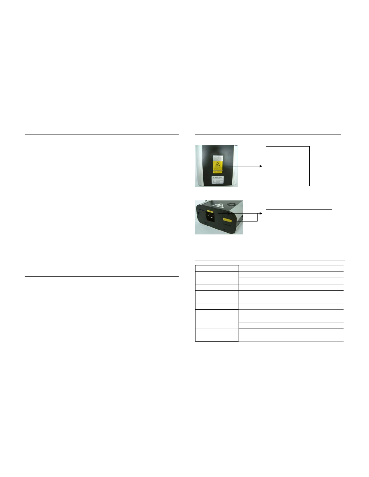
Safety Label Position
Bottom
Front Panel
Specifications
Product Name Magic Box II
Model No. AL20-5R5G/ 20R10G/ 50R20G/ 100R30G/ 200R50G
Laser Diode 4.9~200mW red & 4.9~50mW green
Laser Color Red, Green and Yellow
Net Weight 4Kgs
Power AC 100V~120V or 220V~240V 50/60HZ
Classification 4.9~20mW: 3R/ 30~200mW: 3B
Size (mm) L220 × W280 × H172
Fuse 20mm×2A
Housing Metal
Beam Divergence < 1.5 mrad
Operating temperature 18℃~25℃
Identification label
Certification label
Warning label
Specification label
Laser aperture & aperture label
& warning label
Page 2

Control Panel Introduction
kKey control
1Power Cord Connection
2Fuse
3Power Switch
4 Sensitivity Adjustment Knob
5Microphone
6DMX In & Out
7DIP Switch Pin
jInterlock connector
kKey control
Operating Modes
DMX Operation
DMX operation gives the users freedom to create their own programs tailored to
their own individual needs. To run this unit in DMX mode, connect the unit to any
standard DMX controller via XLR connectors. Please consult DMX controller
manual to determine address.
DMX Signal Levels
Channel-1 Channel-2
Range 0-255 Patterns Selection Range 0-255 Colors and Lines Selection
230-255 Sound Active Mode 233-255 Automatically change all the
patterns in every 5 seconds
225-229 Effect 45 209-232 Automatically change all the
patterns in every 3 seconds
220-224 Effect 44 196-208 Red + Green + Yellow, line2
183-195 Red + Green + Yellow, line1
170-182 Red + Green + Yellow,
dotted line
157-169 Green + Yellow, line2
144-156 Red + Yellow, line2
131-143 Red + Green, line2
118-130 Yellow, dotted line2
105-117 Green, dotted line2
92-104 Red, dotted line2
79-91 Red + Green, line
66-78 Yellow, dotted line1
53-65 Green, dotted line1
:
:
:
:
:
:
40-52 Red, dotted line1
15-19 Effect 3 27-39 Yellow, line
10-14 Effect 2 14-26 Green, line
5-9 Effect 1 1-13 Red, line
0-4 OFF 0 OFF
Stand-Alone Operation (Auto, Sound Active Mode)
Auto mode
The unit runs built-in program to change effects automatically. Set DIP
switch pin 10 to ON, other pins to OFF to run Auto mode.
Sound Active mode
This unit has built-in program that will react to sound and music under Sound
Active mode. Set all DIP switch pins to OFF to run Sound Active mode.
5
4
1
2
3
6
7
j k
Page 3

Operating Modes (Cont.)
Master-Slave Operation (Auto, Sound Active Mode)
This mode allows user to link up to 32 units to run the Master-Slave operation.
In the Master-Slave operation one unit will act as the controlling unit and the
others will react to the controlling unit. Daisy chain your units via the standard
XLR microphone cables in the following configuration: ‘Out’ from the first unit to
‘In’ on the second, ‘Out’ from the second to ‘In’ on the third and so on.
Auto mode
To set the master: Set DIP switch pin 11 and 10 to ON, other pins to OFF.
To set the slaves: Set pin 1 to ON, other pins to OFF.
Sound Active mode
To set the master: Set DIP switch pin 11 to ON, other pins to OFF.
To set the slaves: Set pin 1 to ON, other pins to OFF.
Function Selection Chart
DIP SWITCHES CHART
1 2 3 4 5 6 7 8 9 10 11 12
FUNCTION
OFF OFF OFF OFF OFF OFF OF F OFF OFF OFF
╳
SOUND MODE
OFF OFF OFF OFF OFF OFF OF F OFF OFF ON
╳
AUTO MODE
SET SOUND / AUTO MODE ON
DMX MASTER
ON OFF OFF OFF OFF OFF OFF OF F OFF OFF OFF
DMX SLAVE
SET ADDRESS OFF OFF
DMX MODE
╳ / : Not Used
Fuse Replacement
Always disconnect from main power supply before attempting to replace the fuse
Remove the old fuse from the holder and replace with the exact same type fuse.
Replacement with anything other than the specified part may damage your unit.
Cleaning
Caution: Shut off the main power prior to cleaning unit.
Cleaning mirrors
Use a cotton swab and rubbing alcohol to clean the internal laser mirrors.
Remember to twirl slowly and press gently. Applying to much pressure can
break the mirrors.
Cleaning frequency depends on the environment in which the fixture oper ates.
Cleaning case
Use a soft cloth and normal glass cleaner to clean the casing. Be sure to dry all
parts before plugging the unit back in.
Trouble Shooting
If there is no light from the unit, please check the main power supply and fuse.
If unit does not respond to DMX, please check the DMX cables are connected
properly and are wired correctly.
If unit does not response to the music please adjust the sound-active sensitivity
level by Sensitivity Adjustment Knob.
If the beam is fuzzy please refer to “cleaning“ section to clean the mirror first.
If problems cannot be solved please contact your dealer for service
You can adjust the position of green & red light by below steps to make the best
yellow effect
Step1: Set the ch1 value between 4~7, ch2 value between 66~78.
Step2: Open the cover at front panel. (Caution! Before you open the cover
please project light on to the wall. Never look into beam directly)
Step3: Control these 2 knobs to overlap green and red pattern.
R G Y
Control the green laser pattern horizontally.
Control the green laser pattern vertically.
Page 4

Magic Box II
AL20 Series User Manual
 Loading...