

Page 1
Beta three
User Manual
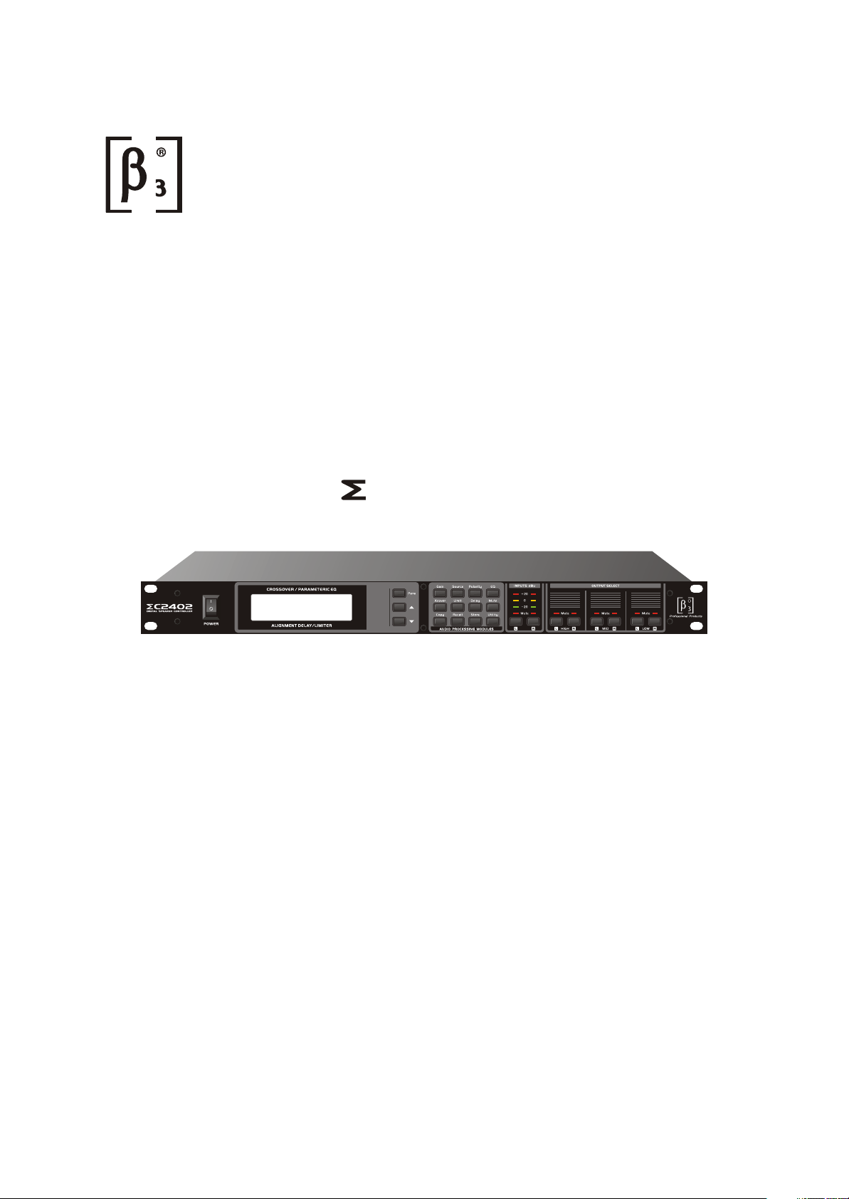
C2402
DIGITAL SPEAKER CONTROLLER
PARA SET
R
ED-B3-MA-070411-001
Page 2

TABLE OF CONTENTS
1. CAUTION
2. INTRODUCTION
2.1 Audio Features
2.2 User Interface
2.3 Other Character
3. UNPACKING
4. AC POWER REQUIREMENTS
5. FRONT PANEL CONTROL FEATURES
6. INTERCONNECT FEATURES
7. .DISPLAYS AND OPERATION
7.1 Gain
7.2 Source
7.3 Polarity
7.4 Peq
7.5 Crossover
7.6 Limit
7.7 Delay
7.8 Mute
1
2
2
2
2
2
3
4
5
5
5
6
6
7
7
7
7.9 Copy
7.10 Recall
7.11 Store
7.12 Other Tools
8. TROUBLESHOOTING
9. SPECIFICATIONS
10.BLOCK DIAGRAM
11.INSTALLTION DIMENSIONS
8
8
8
9
10
11
12
12
Page 3
1. CAUTION
Instruction:
!
Do not open the cover
Do not damage the cord
The lightning flash with arrowhead symbol within the equilateral; triangle is
intended to alert the user to the presence of un-insulated angerous voltage
within the product's enclosure that may be of sufficient magnitude to constitute
a risk of electric shock.
The exclamation point within the equilateral triangle is intended to alert the
user to the presence of important operation an maintenance (servicing)
instructions in the literature accompanying this appliance.
Do not open the cover to avoid the risk of electric shock caused by high
voltage parts in the product. Any problems caused by user's wrong actions
are out of warranty.
the cord Please hold the plug when pulling out or plug in the cord. Do not
pull out or touch the cord with wet hand, or it will cause the risk of electric
shock. Power supply cords should be routed so that they are not likely to
be walked upon or pinched by items placed on or against them. When
removing the cord from a power outlet be sure to remove it by holding the
plug attachment and not by pulling on the cord.
Avoid object and liquid entry
Abnormal status
Nonuse for a long time
Take care that objects do not fall into and that liquids are not spilled into
the inside of the product.If the object or liquid enter the product, please
ask qualified personnel to check it.
In the event of abnormal noise and smell, please put off the power supply
and pull out the cord, please ask qualified personnel to check it.
When nonuse it for a long time, please put off the power supply and pull
out the cord to avoid the unexpected dangers.
1
Page 4

2. INTRODUCTION
Thank you very much for the purchasing of C2402 digital speaker controller whose
brand is 3 from Elder company. The product have cohered Elder company's more than
ten years' cherish experience in the field of professional audio system. The excellent
voice performance and the competitive operate to price will guarantee your profit from
your investment.
C2402 provide digital process to the two way analogue input voice signal and the
function of frequency process and speaker management. It is very suitable for the
improvement of the sound reinforcement in the middle small place. The function key's
laying are reasonable and the display is simple and look-easy. It is very convenient for
the system test.
2.1 Audio Features
C2402 get the sample at 48Khz,the distinguish rate is the famous 24's - A/D and
D/A switch technology, messenger's handling take the high capability 32 DSP and filter.
The digital processor include the gain controller, polarity, PEQ(peak, slope, limit and
band pass),delay, crossover(the types are Butter worth/Bessel/Linkwitz, the slope rate
are 12dB-36dB) limit. All the input and output connector take the precise electronic
equalization and RF protect circuit an the standard socket is reliable.
2.2 User Interface
the panel include the signal peak indicator with LED input, user process information with
LCD display. The operate key include input, output, and frequency module function
adjustment.
2.3 Other Character
have 20 collocated process for user's edition, save and using. for user's digital safty
system lock, LCD compare adjustment.
3. UNPACKING
Each product have to be packed carefully before ex warehouse as part of our quality
system control. Pleas check carefully on the product's appearance. To the future's
convenience of transport and guarantee the product safty and capability, please keep
all the packing material. And please notice the distributer immediately in the convenience
of provide the letter guarantee if find the appearance damage on the product.
4. AC POWER REQUIREMENTS
Please confirm the local voltage is same with input identification on the AC socket or being
included within the range before connect this machine to the local power. The machine
have fuse inside, and general speaking the fuse is damaged if the machine fail to connect
the power, in this situation please contact with our professional repair person to change
another new one same as the fuse type.
2
Page 5
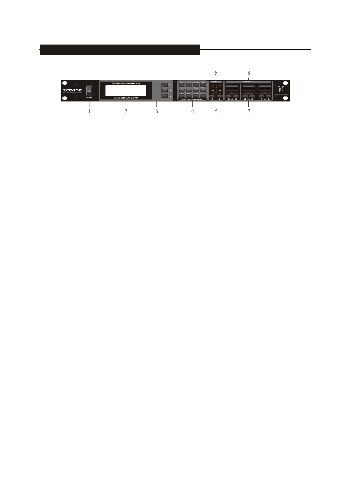
5. FRONT PANEL CONTROL FEATURES
PARA SET
R
1.Power switch: put the 1 means open and 0 means close
2.LCD display: display the operate situation, e.g. the channel's module's set for the digit
3.Parameter set: choose the parameter need to be adjusted and set the +/- key when the Para
Is more than two
4.Function key and assistant key on the module:
Gain: input/output channel signal gain control
Source: choose the voice source on the output channel(only for the woofer)
Polarity: choose the signal polarity on the output channel
EQ: input/output channel parameter realization
Xover: output channel crossover
Limit: output channel signal limit
Delay: input/output channel signal delay
Mute: input/output signal mute
Copy: the copy for the channel or the same parameter(only for the same group channel)
Recall: process's adjustment
Store: process's saving
Utility: assistant function including the system lock switch and LCD contrast
5.Input channel's choose: choose the related input channel under the module for function of L/R
6.Input channel signal indicator: peak indicator,-20db(green),+15db(yellow),+20db(red)
7.Output channel choose key: L-High-R, L-Mid-R,L-Low-R, under the function module,
choose the related key to adjust the related output channel
8.Channel mute indicator: on means output mute, off means normal output
3
Page 6
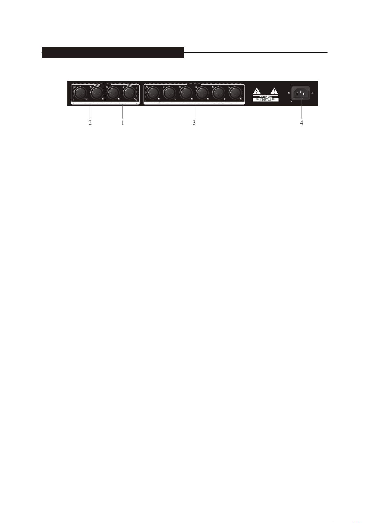
6. INTERCONNECT FEATURES
INPUTS
RIGHT LINK-OUT LEFTLINK-OUT LOW
OUTPUTS
MID HIGHRIGHT RIGHT RIGHTLEFT LEFT LEFT
1. L(Left) channel audio input socket and link-out socket
2. R(Right) channel audio input socket and link-out socket
3. L/R channel high, mid, low frequency signal output, total 6chs, usually config as
3XCrossOver of stereo
4. Power input socket, connect to local AC power supply Net.
220V-240V,50Hz/60Hz
4
Page 7

7. DISPLAYS AND OPERATION
Power on the device and it will display the current Program number and name like following picture:
7.1 Gain
Press the Gain key and enter into the gain control interface like the picture:
Input and output gain can be adjusted separately, the range is -40db,+12db,the precise is 0.5dB.
Input chanelLeft
Gain-40~+12dB
Press the channel choose key and choose the related channel need to be adjusted, put the +/-
.
key to adjust the gain electric frequency.
Parameter set key:
Use Para key to choose the parameter need to be adjusted ( Only available for more than
one Parameter).
+/- key is for changing present Para value
(Remark: " " is flash symbol, if there are several Para in one function can be adjusted,
please press the para key on the panel to move the flash to correspondent para position.)
7.2 Source
Press the source key and enter into the source choose interface like the below picture:
Only two woofer channels L-Low-R can choose the source which is Left, Right, and Left Right.
Output channel-Low
Music source Left+Right
Press the channel choose key and choose the related channel need to be adjusted, put the +/-key to choose the source.
7.3 Signal Polarity
Press the polarity key to enter into the signal polarity adjustment channel, like the below picture:
Only the output channel signal polarity can be adjusted and the range is Normal and Reverse.
Output channelL-Low
Polarity Normal
Press the channel choose key and choose the related channel need to be adjusted, put the +/-key to adjust the signal polarity.
5
Page 8

7. DISPLAYS AND OPERATION
7.4 PEQ
Press the EQ key to enter into the adjust interface of output PEQ as the below picture:
First EQ point1
Output channel-low
Gain -10.5dB
EQ center frequency
Filter genre
Gain Q value
Press the channel choose key and choose the related channel need to be adjusted and press
the Para key to choose the parameter which can be changed by the key of +/--.
There are 4 PEQ point in each input channel and 6 in the output channel.
The filter's type : OFF, Peaking, Notch, Hi-shelf, Loshelf, Band pass and their function is
describe as below:
Peaking: it is the peak filter which in most of the time to be used to modify the voice
system's frequency curve and voice tamber.
Hi-Shelf: it is the treble filter and used as the treble's raise and lower
Lo-Shelf: it is the woofer filter and used as woofer's raise and lower
Band pass: it is band pass filter, not used frequently besides the special requirement
of bandpass
Notch: it is limit filter mainly for the limit of fix howling for the reason of sound
reinforcement's lack.
The filter gain's adjustment range is 12Db+12.0db and the precise is 0.5db;
The centre frequency is as per the 1/12oct and totally 121 frequency point can be
choosed, the Q number is the filter quality factor.
7.5 Crossover
Press the crossover key to enter into the adjust interface of the output channel signal HPF
and LPF as the below picture.
Output channel-low
Crossover frequency
Press the channel selection key and choose the related channel need to be adjusted and
press the Para key to choose the parameter which changed by the key +/---
Each output channel include one HPF and LPF filter, and the below is their types:
12dB/oct Butterworth,24dB/oct Butterworth, 36/oct Butterworth,
12dB/oct Bessel,24dB /oct Bessel,36db /oct Bessel
12dB/oct Linkwtz,24 dB/oct Linkwtz
Crossover point frequency has 121 points available for choice based on 1/12 oct.
6
Choose low pass or high pass
filter genre
Page 9

7. DISPLAYS AND OPERATION
7.6 Limitations
When pressing Limit button, you will enter the adjusted screen of limitation function of
output signal, see the following:
Output channel-low
Ratio of compression
time of startup
value of door limit
time of release
Press channel, choose corresponding adjustable channel, and press Para button and then
choose parameter, +/- to change the parameter value.
The limitation range is:-20dBu--+20dBu
Compression ratio range: 1:1~INF:1, 1:1 expresses direct channel for limitation
equipment, 1NF expresses limitation equipment.
Range of starting time: 0.010ms ~820ms
Range of releasing time: 100ms ~4700ms
7.7 Delay
Press Delay and enter input, output channel signal delays the adjusted screen, see the
following:
Output channel L-Low
Distance of delaying
(meter)
delaying time (ms)
distance of delaying
(inch)
All the channels of this equipment share the delaying line, therefore we can distribute the
delaying time dynamically, every channel can delay at most 40ms.
Press Chooses , choose corresponding adjustable channel, and press +/- to adjust time
of signal delaying, at the same time, use meter and inch as the delaying distance.
7.8 Mute
Press Mute and then enter input, the mute screen of output channel signal, see the following:
Repress Mute , all the channels are mute, press the choosing channel and then control
corresponding mute of the channel to open or close.
7
Page 10

7. DISPLAYS AND OPERATION
7.9 Copy
Press copy and enter the screen of parameter copy, and then copy the present
parameter to another channel, see the following:
Choose the present
channel
choose parameter
Choose the aim channel
automatically
Press the choosing channel to choose the present channel,(the aim channel will
choose another channel in one group) ,press +/-to choose the copy parameter ,after
choosing, repress copy button to confirm the copy one.
Parameter range: ALL---copy all the parameter of the present channel;
EQ---copy the parameter balanced setting of the channel;
XOVER---copy the setting of crossover of the present channel;
Gain---copy the gain setting of the present channel;
Limit---copy limitation setting of the present channel;
Delay---copy the delaying setting of the present channel.
7.10 Recall Program
Press Recall and enter the recall screen of previous program (if using the present
channel, just give up the present edited parameter, and then recover the original setting),
see the following:
Program No.
Program name
Press +/-to choose the adjustable program, and then press Recall to confirm recall.
7.11 Store Program
Press Store and enter the protecting screen of previous program, we can keep the
present program or put the present program into different program No. or program name.
See the following:
Program No.
Program name
Press Para to choose present parameter ---program No., press +/- to store new program No. ;
Press Para to choose present parameter---program name, press+/- to enter program name,
press Para pad
After finishing setting, repress store and confirm storing.
8
Page 11

7. DISPLAYS AND OPERATION
7.12 Other Tooling
Press utility to enter the setting screen of assistant function, we can set the plate lock
and contrast, see the following:
Switch of system lock
LCD contrast
Press Para to choose LCD contrast, and press +/- to adjust contrast, we can choose
00(weak), 01(normal), 02(strong).
Press Para to choose plate lock for the setting of switch, press+/-, and transfer
unlock/lock, lock here means the plate lock is effective, expect mute and utility ,other
ones we can not edit ,off means all the functions can be operated on the boards.
9
Page 12

8. TROUBLESHOOTING
Problem
Cannot POWER ON
Parts of key on panel
cannot operation
No signal output or is
very small
Overload light is often on
Sound faulty,
some frequency is lost
Over white noise
Check And Solution
Whether power cable connect to power supply net,
or the switch not press down
Key lock function enable or not?
Whether input, output are in the condition of mute?
Whether input, output gain decay overabundance?
Whether input, output signal route is correct?
If setting crossover ,whether HPF corner frequency is
lower than the LPF cornet frequency?
Lower the input signal, the biggest input is +20dbu
If you want to input full way signal, please check
whethercrossover is open and lead to cut off or
lower down somefrequency ?
Please check whether the input gain is too small, but
output gain is too much?
Contrast of screen
is in deviation
System hum noise
As the temperature features of lcd, when the
temperatureis too high or too low, the contrast of
screen will decease or increase, please adjust the
contrast under utility.
Please check the connection of the system,
especially pay attention to the connection
to the ground .
10
Page 13

9. SPECIFICATIONS
Analog Input:
Input: balance XLR-3-32 input socket
Input Impedance: 10k
Max input level: +20dBu
A/D Convertor: 48kHz sample frequency, 24bits linear
Analog Output:
Input: balance XLR-3-32 out put socket
Output Impedance: 100
Load impedance: 600
Max input level: +20dBu
Simulation Sound:
Frequency response: 20Hz~20 kHz (+0.3/-0.3dB), 10Hz~30kHz (+0.3/-3.0dB)
Dynamic range: 110dB(A -Weight)
Total distortion and noise : < 0.006%
Min time of delaying: about 1.2ms (we set the delaying parameter of signal input and output as 0)
Others:
Power requirement: AC 220V 50Hz
Power consuming:18W
Dimension(W D H): 482 172 45mm
Weight: 3.0kg
Operation temperature: 0~+40
Storage temperature: -10~+60
Accessories:
Power cable: 1 pcs
The fuse:250mA@220V AC delaying
User manual: 1pcs
Exterior design and specifications are subject to change without notice
11
Page 14

10.BLOCK DIAGRAM
INPUT
Left
Right
Only LOW output may be selected source
Input 4EQs,Output 6EQs&HPF+LPF
EQ type:Peaking/Bandpass/Hi-shelf/Lo-Shelf/Notch
Delaytime dynamic assignment,max to 42ms
HPF+LPF type:-12~-36dB/oct,ButterWorth/Bessel/LinkWitz-Riley
Gain PEQ
Gain PEQ
Delay Mute
Delay Mute
Source:
Left
Right
Left+Right
11.INSTALLTION DIMENSIONS
Delay
Delay
Delay
Delay
Delay
Delay
HPF+LPF
HPF+LPF
HPF+LPF
HPF+LPF
HPF+LPF
HPF+LPF
PEQ
PEQ
PEQ
PEQ
PEQ
PEQ
Gain
Gain
Gain
Gain
Gain
Gain
Limit
Limit
Limit
Limit
Limit
Limit
Mute
Mute
Mute
Mute
Mute
Mute
OUTPUT
Left
HIGH
Right
Left
MID
Right
Left
LOW
Right
430.5
482
44.5
44.5
12
Page 15

C2402
www.elderaudio.com
 Loading...