

Page 1
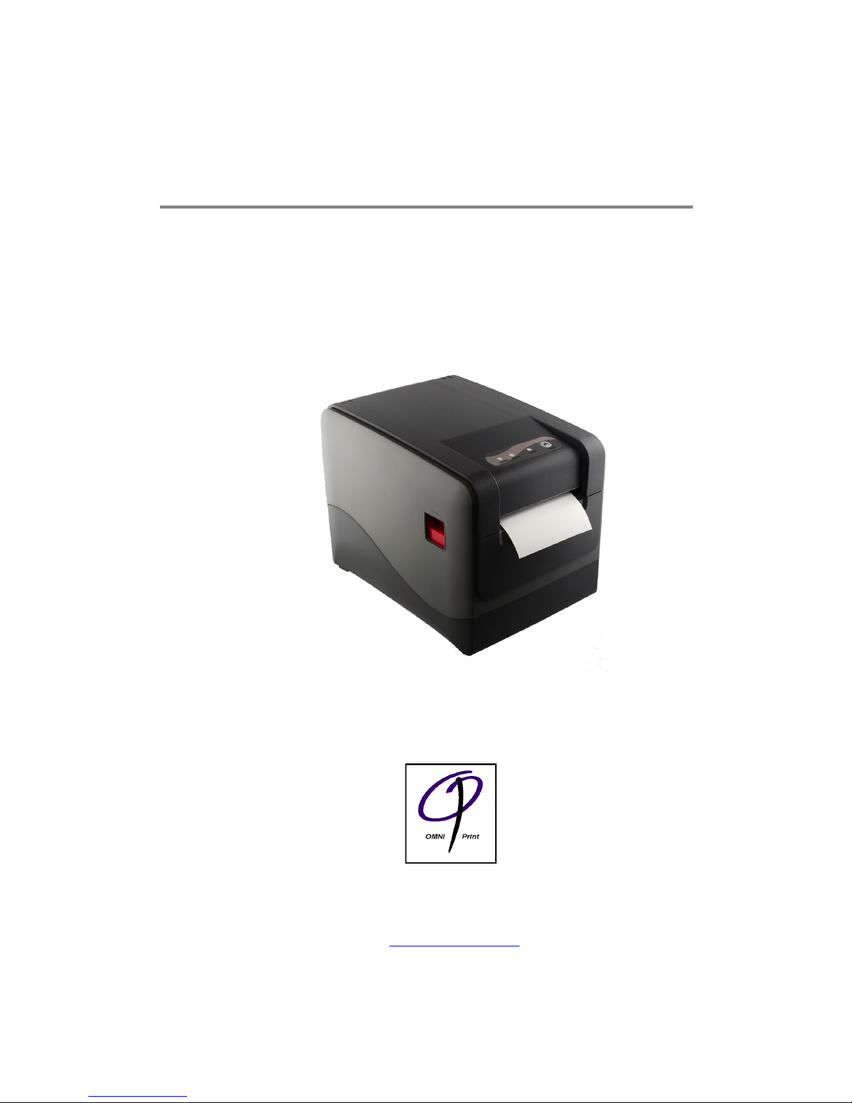
OM9500F
Thermal Receipt printer
Technical Manual
Revision: 1.0
January 8, 2018
Omniprint Inc.
1923 East Deere Ave., Santa Ana, California 92705, U.S.A.
T: 949.833.0080 :: F: 949.833.0040
www.omniprintinc.com
Page 2

OM9500F Technical Manual
Rev.
1.0
Document No.: 19B00271
Date: Jan 08, 2018
Page: 2
TABLE OF CONTENTS
1. General Specifications
Printing Specifications
Character Specifications
Auto Cutter
Paper Roll Supply Device
Paper Specifications
Printable Area
Printing and Cutting Positions
Internal Buffer
Electrical Characteristics
EMI and Safety Standards Applied
Reliability
Environmental Conditions
2. Configuration
Interface
RS-232 serial interface
Specifications
Switching between on-line and off-line
Interface connector terminal assignments and signal functions
Serial interface connection example
Interface Connector
Data Receiving Timing(Compatibility Mode)
3. Connectors
Interface Connectors
Electrical Characteristics
Drawer kick-out Connector (Modular Connector)
4. Printer Appearance
5. Paper Loading
6. Dip Switch Setting
7. Control Command Summary
Page 3

OM9500F Technical Manual
Rev.
1.0
Document No.: 19B00271
Date: Jan 08, 2018
Page: 3
1. General Specifications
1.1 Printing Specifications
1) Printing method: Thermal line printing
2) Dot density: 203dpi × 203dpi. The number of dots per 25.4mm(1")
3) Printing direction: Unidirectional with friction feed
4) Printing width: 75mm (2.83"), 576 dot positions
5) Characters per line: Font A: 12 x 24 dots, or 48 CPL (default)
Font B: 9 x 17 dots, or 64 CPL
Chinese: 24 x 24 dots,
6) Printed dot dimension: 0.11mm Î0.13mm
7) Printing speed: High speed mode:
65 lines/second maximum
(1/6inch feed) (at 24V, 20℃)
Approximately 200 mm/sec maximum
(approximately 8 inchs/sec maximum)
NOTE: Speeds are switched depending on the applied voltage to the printer and
head temperature conditions automatically.
NOTE: There may be variations in printing after switching the mode of the printing
speed. To prevent this for logo printing with ESC* command, using a downloaded bit
image is recommended. Change in printing speed does not occur during down loaded
bit image printing.
8) Paper feed speed: Approximately 250mm/second
(approximately 12 inches/second)
(continuous paper feeding)
9) Line spacing (default): 1/6 inch (4.23mm)
Programmable by control command.
1.2 Character Specifications
1) Number of characters: Alphanumeric characters: 95
Extended graphics: 128 × 7 pages
International code pages: 32
2) Font Definition: Font A: 12 ⅹ 24 (Set as default)
Font B: 9 ⅹ 24
Page 4
OM9500F Technical Manual
Rev.
1.0
Document No.: 19B00271
Date: Jan 08, 2018
Page: 4
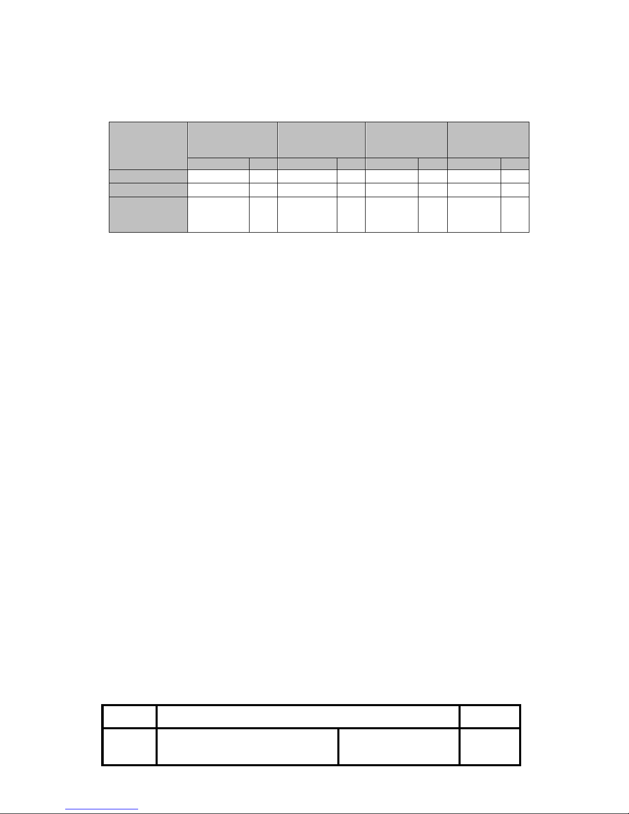
3) Character size:
Standard
Double-height
Double-width
Double-width /
Double-height
WⅹH
CPL
WⅹH
CPL
WⅹH
CPL
WⅹH
CPL
Font A 12ⅹ24
1.25ⅹ3.39
46
1.25ⅹ 6.77
42
2.5ⅹ3.39
23
2.5ⅹ6.77
23
Font B 9ⅹ24
0.875ⅹ 3.39
61
0.875ⅹ6.77
61
1.75ⅹ3.39
30
1.75ⅹ6.77
30
Chinese
24ⅹ24
3ⅹ3.39
23
3ⅹ6.77
23
6ⅹ3.39
11
6x6.77
11
Space between characters is not included.
CPL = Characters per line
Measurements in mm
1.3 Auto Cutter
Partial cut: Cutting with one point center uncut
NOTE: To prevent dot displacement, after cutting, paper must be fed
approximately 1mm(14/360 inches) or more before printing.
1.4 Paper Roll Supply Device
1) Supply method: Drop-in paper roll
2) Near-end sensor:
a) Detection method: Micro switch
b) Paper roll spool diameter: Inside: 12mm (.47″)
Outside: 18mm (.71″)
c) Near-end adjustment: Adjusting screw
d) Remaining amount: Fixed position #1 (approximately
23mm(0.9″)) #2 (approximately
27mm(1.06″))
NOTE: You can use a command to stop printing upon detection of a paper
near-end.
1.5 Paper Specification
1) Paper type: Specified thermal paper
2) Type: Paper roll
3) Paper width: 79.5 ± 0.5 mm(3.13"±0.02")
4) Paper roll size: Roll diameter: 83mm Max
5) Paper roll core diameter: Inside: 12mm(.47")
Outside: 18mm(.71")
NOTE: Paper must not be pasted to the core.
Page 5
OM9500F Technical Manual
Rev.
1.0
Document No.: 19B00271
Date: Jan 08, 2018
Page: 5
1.6 Printable Area
1) Paper roll
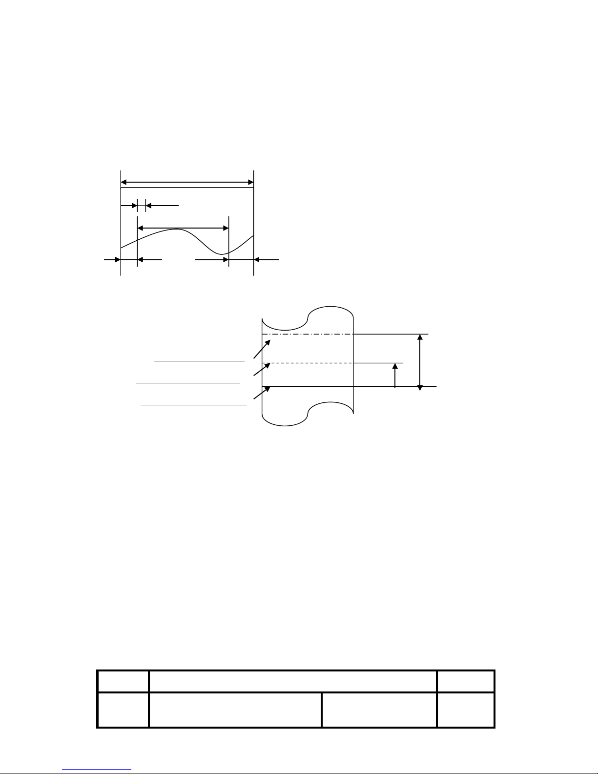
The printable area of a paper with width of 79.5± 0.5mm(3.13"±0.02") is 72.2 ±
0.2mm(2.84"±0.008")(576dots) and the space on the right and left sides are
approximately 3.7 ± 2mm(0.15"±0.079").
a=79.5±0.5mm(3.13"±0.02")
a b=0.125mm±0.05mm(.056"±.002")
c=69mm±0.2mm(2.84±.008")
b d=3.7±0.2mm(0.15"±0.079")
□□□……………□□ e=3.7±0.2mm(0.15"±0.079")
c [All the numeric values are typical.]
d e
< Figure 1.1 Paper Roll Printable Area >
1.7 Printing and Cutting Positions
Manual-cutter position
Auto-cutter blade position
Center of the print dot line
< Figure 1.2 Printing and Cutting Positions >
NOTE: Numeric values used here are typical values; the values may vary slightly as a
result of paper slack or variations in the paper. Take the notice into account when
setting the cutting position of the auto-cutter.
1.8 Internal Buffer
1) Receive buffer: 8kbyte
1.9 Electrical Characteristics
1) Supply voltage: +24 VDC ± 7%
2) Current consumption (at 24V):
Operating: Approx. 1.5A (at ASCII Printing)
Peak: Approx. 10A (at print duty 100%, For 10
seconds or less)
Stand-by: Approx. 0.15A
Page 6
OM9500F Technical Manual
Rev.
1.0
Document No.: 19B00271
Date: Jan 08, 2018
Page: 6
1.10 EMI and Safety Standards Applied
1) Europe: EMI – EN55022 CLASS A
EMS – EN61000-3-2
EN61000-3-3
EN50082-1
Safety Standard: EN60950
2) North America: EMI - FCC Part#15 Class A
Safety Standards- UL(1950), c-UL(No.950)
1.11 Reliability
1) MCBF: 200 million lines
(based on an average printing rate of 12.5% with paper thickness
in the range 65 ㎛ to 75 ㎛).
150 million lines
(based on an average printing rate of 12.5% with paper thickness
in the range 76 ㎛ to 150 ㎛)
2) Cutter Life: 10.0 million cuttings
(if the paper thickness is between 65 and 100 ㎛)
1.12 Environmental Conditions
1) Temperature: Operating: 5° to 45°C (41° to 113°F)
Storage: -10° to 50°C (14° to 122°F)
(except for paper)
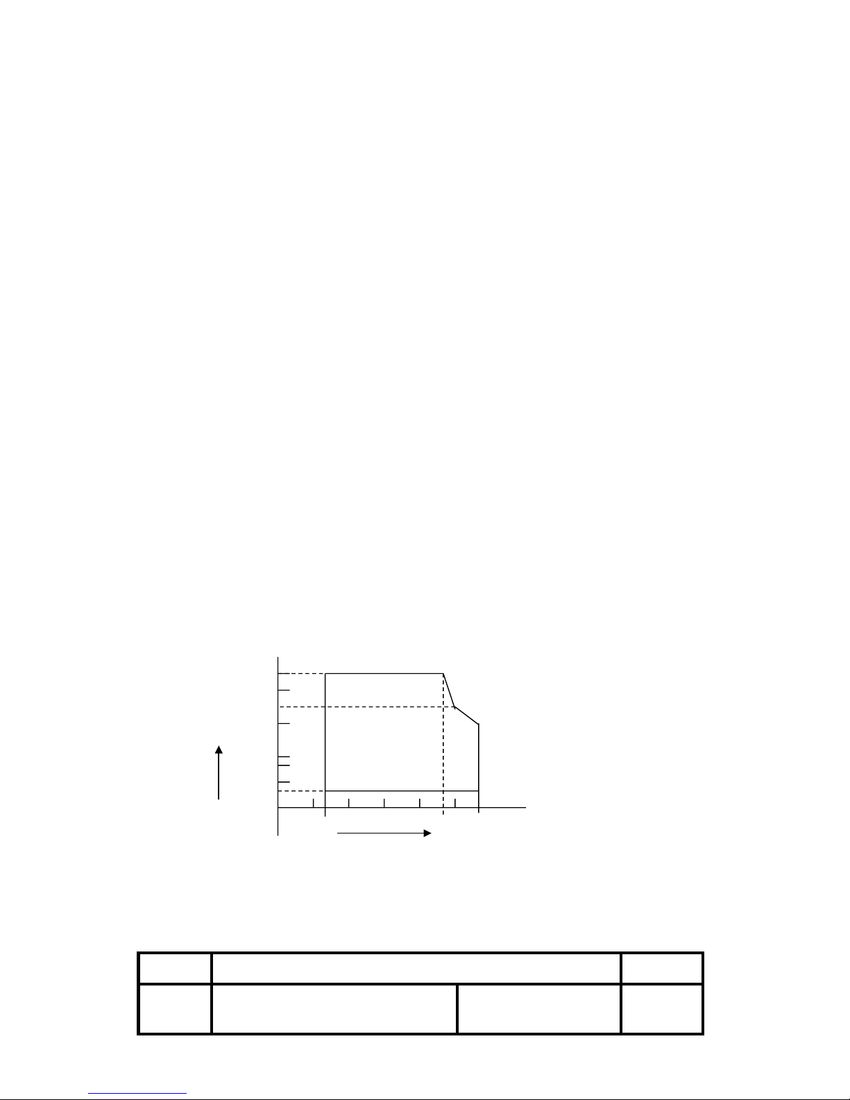
2) Humidity: Operating: 10 to 90%RH
Storage: 10 to 90%RH (except for paper)
[RH]
90
80
60
Relative humidity
40 Operating environment range
20
10
0 0 10 20 30 40 50
Ambient temperature [°C]
< Figure 1.3 Operating Temperature and Humidity Range >
Page 7
OM9500F Technical Manual
Rev.
1.0
Document No.: 19B00271
Date: Jan 08, 2018
Page: 7
2. Configuration
2.1 Interface
2.1.1 RS-232 serial interface
2.1.2 Specifications
Data transmission: Serial
Synchronization: Asynchronous
Handshaking: DTR/DSR or XON/XOFF control
Signal levels: MARK= -3 to –15V: Logic “1”
SPACE= +3 to +15V: Logic “0”
Baud rage: 9600, 19200, 38400, 115200 bps
Data word length: 7 or 8 bits
Parity Settings: None, even, odd
Stop bits: 1 or 2
Connector (printer side): Female DB-9 pin connector
NOTE: The data word length, baud rate, and parity depend on the
DIP switch settings.
2.1.3 Switching between on-line and off-line
The printer does not have an on-line/off-line switch.
The printer goes off-line:
•Between when the power is turned on (including reset using the
interface) and when the printer is ready to receive data.
•During the self-test.
•When the cover is open.
•During paper feeding using the paper feed button.
•When the printer stops printing due to a paper-end (in cases when an
empty paper supply is detected by either paper roll end detector or the
paper roll near-end detector with a printing halt feature by
ESC c4).
•During macro executing stand by status.
•When a temporary abnormality occurs in the power supply voltage.
•When an error has occurred.
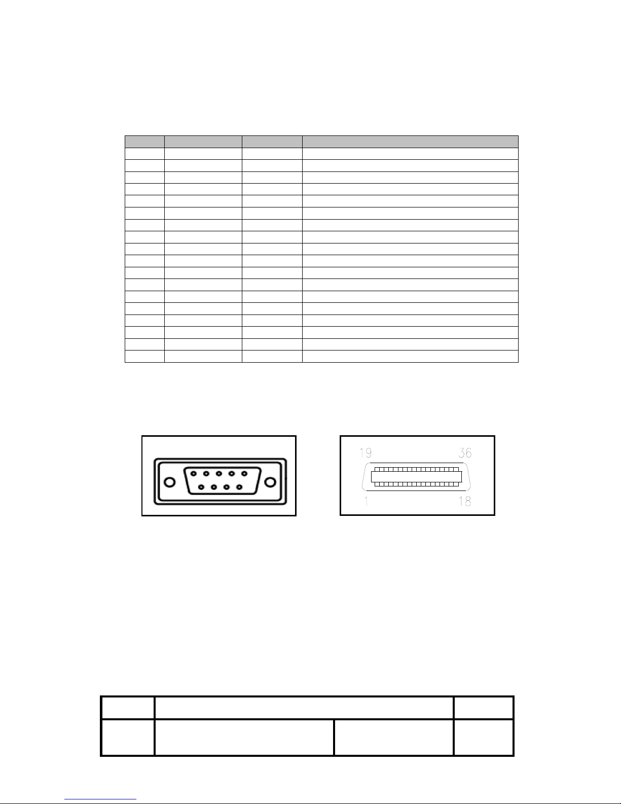
2.1.4 Interface connector terminal assignments and signal functions
PIN
SIGNAL
I/O
DESCRIPTION
2
TXD
-
Printer transmit data line RS-232C level
3
RXD
-
Printer receive data line RS-232C level
6
DTR
Output
Printer handshake to host line RS-232C level
4
DSR
Input
Data Send Ready
5
GND
-
System Ground
Page 8
OM9500F Technical Manual
Rev.
1.0
Document No.: 19B00271
Date: Jan 08, 2018
Page: 8
2.1.5 Serial interface connection example
Host side Printer side
TXD ………………………………… RXD
DSR ………………………………… DTR
RXD ………………………………… TXD
DTR ………………………………… DSR
FG ………………………………… FG
SG ………………………………… SG
NOTES: ◦Set the handshaking so that the transmit data can be received.
◦Transmit data to the printer after turning on the power and
initializing the printer.
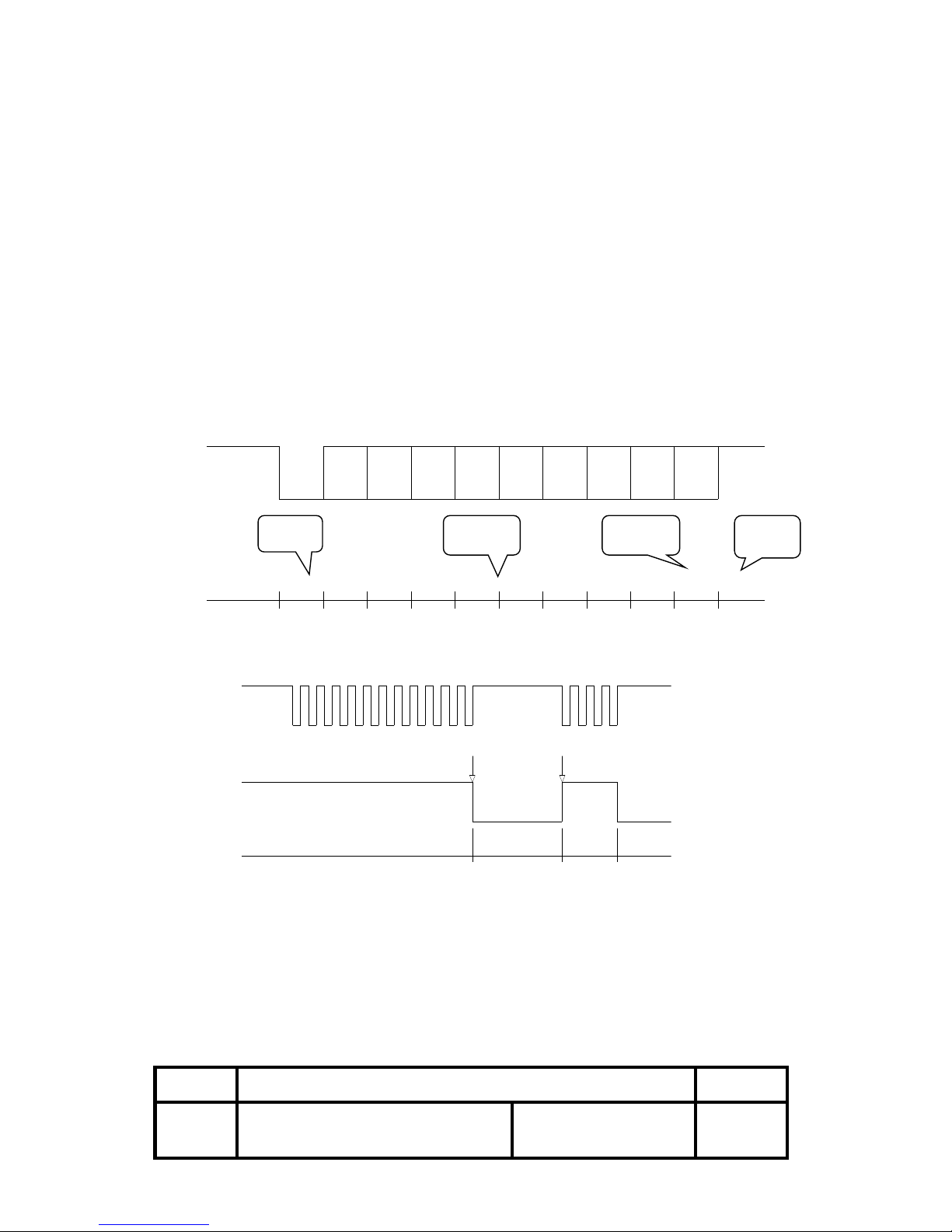
< Figure 2.1 Serial transmission bit frame >
< Figure 2.2 Line transmission with protocol >
ready busy re ady busy
buffer*full
buffer*emptied
"1"
"0"
"0"
"1"
RxD
DTR
B0 B1 B2 B3 B4 B5 B6 B7START
PARITY
"1"
"0"
STOP
7 or 8
Bit
None or
1 Bit
1 or 2
Bit
Page 9
OM9500F Technical Manual
Rev.
1.0
Document No.: 19B00271
Date: Jan 08, 2018
Page: 9
2.1.6 Centronics parallel interface
2.1.7 Interface Connector
<D-SUB 9 Female Serial Port> <D-SUB Centronics Parallel Port>
PIN
SIGNAL
I/O
DESCRIPTION
1
STROBE-
Input
Synchronize signal Data received
2-9
DATA0-7
Input
Data bit Transmitted 0-7
10
ACK-
Output
Data receiving competed
11
BUSY
Output
Impossible to printer data receiving
12
PE
Output
Paper empty
13
SELECT
Output
Printer’s status for ON/OFF line
14
AUTO FEED-
Input
ND
15
NC -
16
GROUND
-
System Ground
17
CHASSIS GND
-
System Ground
18
LOGIC-H
-
+5V
19-30
GROUND
-
System Ground
31
INIT-
Input
Initialize
32
ERROR-
Output
Printer Error
33
GROUND
-
System Ground
34
NC -
35
+5V - +5V
36
SELECT IN-
Input
ND
5 1
Page 10
OM9500F Technical Manual
Rev.
1.0
Document No.: 19B00271
Date: Jan 08, 2018
Page: 10
2.1.8 Parallel Interface
1) Specifications
Data transmission: 8-bit parallel
Synchronization: STROBE pulse supplied by host computer.
Handshaking: ACK and BUSY
Connector: D-SUB 25(male) or equivalent
DATA Data n Data n+1
THold-1
nStrobe
tSetup tSTB tHold-2
Busy Peripheral Busy
tReady tBUSY
nAck
tReply tACK tnBUSY
tNext
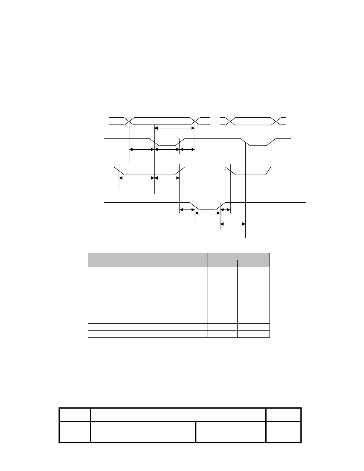
2.1.9 Data Receiving Timing (Compatibility Mode)
Characteristics
Symbol
Specifications
Min [ns]
Max [ns]
Data Hold Time (host)
tHold-1
--
500
Data Hold Time (printer)
tHold-2
--
--
Data Setup Time
tSetup
--
500
STROBE Pulse Width
tSTB
--
500
READY Cycle Idle Time
tReady
--
--
BUSY Output Delay Time
tBUSY 0 500
Data Processing Time
tReply 0 ∞
ACKNLG Pulse Width
tACK
500
10 ㎲
BUSY Release Time
tnBUSY 0 ∞
ACK Cycle Idle Time
tNEXT
--
0
*The printer latches data at a nStrobe ↓timing
Page 11
OM9500F Technical Manual
Rev.
1.0
Document No.: 19B00271
Date: Jan 08, 2018
Page: 11
3. Connectors
3.1 Interface Connectors
Refer to Section 2.1, Interface
3.2 Electrical Characteristics
1) Input Voltage: DC 24V ± 10%
2) Current Consumption: Operating: Approx. 1.5 A (at ASC∥ printing)
Peak: Approx. 10 A (at print duty 100%, For 10 seconds or less)
Stand-by: Approx. 0.15 A
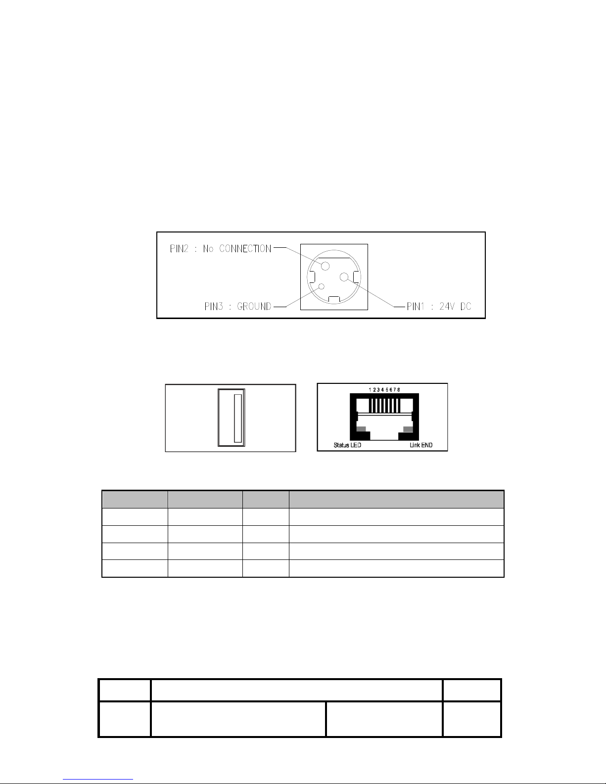
3) Power Connector
3.3 USB and Ethernet Connection
USB Connector Ethernet Connector
-USB Interface
PIN
SIGNAL
I/O
DESCRIPTION
1
+5V
-
+5V
2
DATA-
-
Printer transmit data line
3
DATA+
-
Printer transmit data line
4
GND
-
System Ground
Page 12
OM9500F Technical Manual
Rev.
1.0
Document No.: 19B00271
Date: Jan 08, 2018
Page: 12
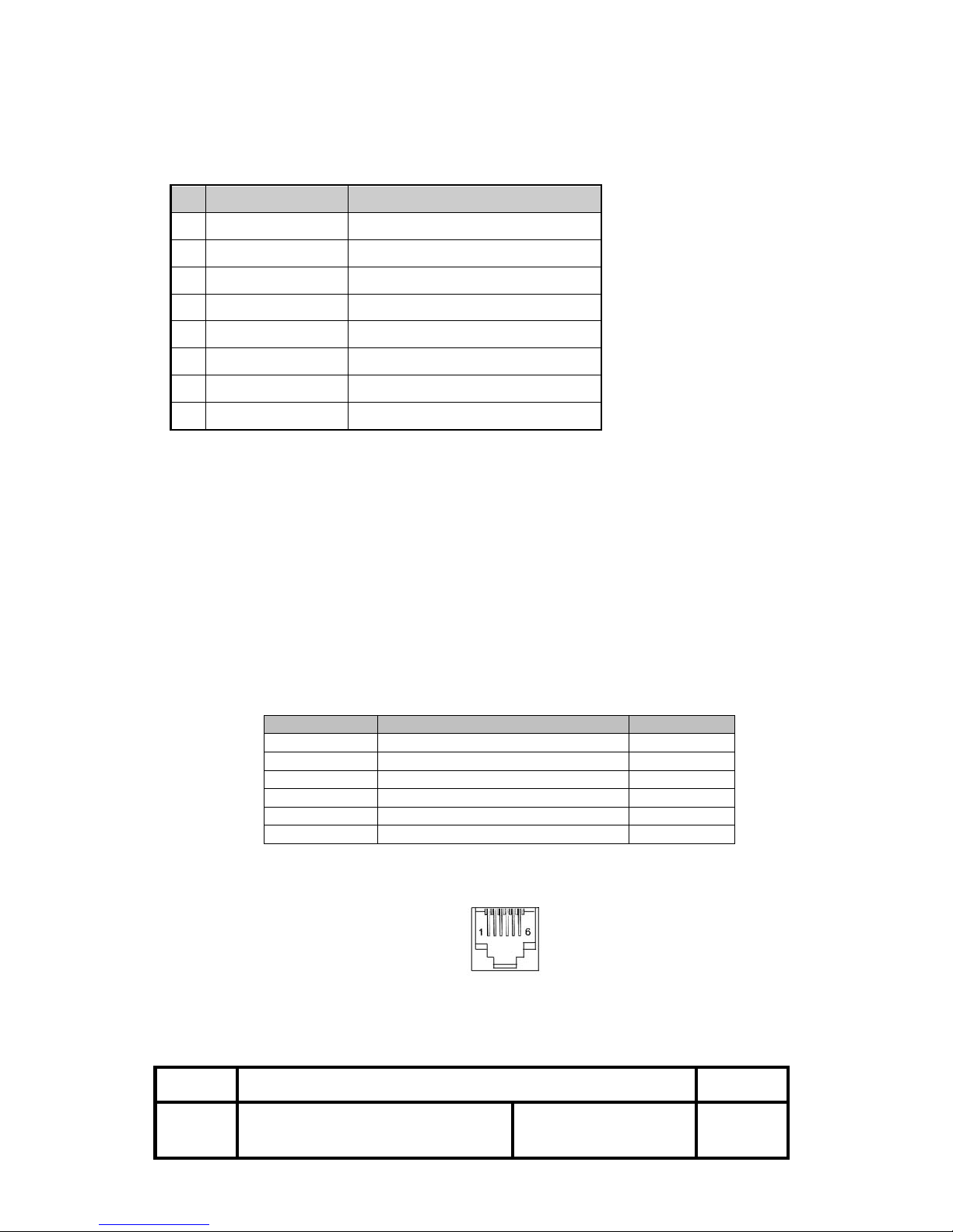
-Ethernet Interface
PIN
SIGNAL
I/O
1
Data Out +
Output Data +
2
Data Out -
Output Data -
3
GND
Ground
4
Data IN +
Input Data +
5
Data IN -
Input Data -
6
N.C
7
N.C
8
N.C
3.4 Drawer Kick-out Connector (Modular Connector)
The pulse specified by ESC p or DLE DC4 is output to this connector. The
host can confirm the status of the input signal by using the
DLE EOT, GS a, or GS r commands.
1) Pin assignments: Refer to Table 2.2.2
2) Connector model:
Printer side: RJ11 6P6C, AMP P/N 115837
User side: 6-position 6-contact (RJ12telephone jack)
< Drawer Kick-out Connector Pin Assignments >
Pin Number
Signal Name
Direction
1
Frame GND
-
2
Drawer kick-out drive signal 1
Output
3
Drawer open/close signal
Input
4
+24V - 5
Drawer kick-out drive signal 2
Output
6
Signal GND
-
+24V is output through pin 4 when the power is turned on. However, pin 4 must by
used only for the drawer.
< Figure 3.1 Drawer Kick-out Connector >
3) Drawer kick-out drive signal
Output signal: Output voltage: Approximately 24V
Output current: 1A or less
Page 13
OM9500F Technical Manual
Rev.
1.0
Document No.: 19B00271
Date: Jan 08, 2018
Page: 13
CAUTION: To avoid an over current situation, the resistance of the drawer kick-out
solenoid must be 24 Ω or more.
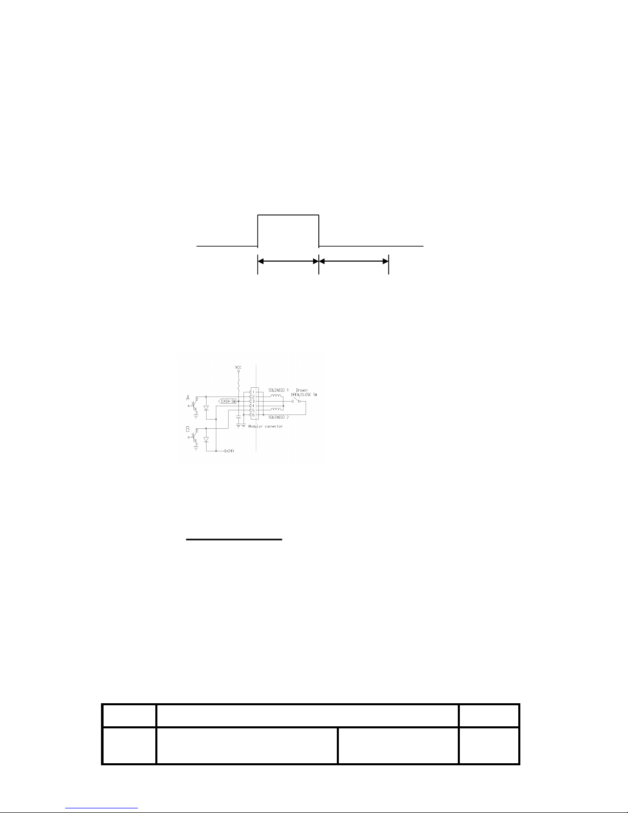
Output waveform: The output shown in Figure 3.2 are inputs to points A and B
in Figure 3.3
t1 (ON time) and t2 (OFF time) are specified by ESC p or
DLE DC4.
t1 x 2ms : t2 x 2ms
< Figure 3.2 Drawer Kick-out Drive Signal Output Waveform >
4) Drawer open/close signal
Input signal level (connector pin 3): “L”= 0 to 0.8V
“H”= 3 to 5V
< Figure 3.3 Drawer Circuitry >
NOTE: 1. Use a shielded cable for the drawer connector cable.
2. Two driver transistors cannot be energized simultaneously.
3. The drawer drive duty must by as shown below.
ON time
≤ 0.2
(ON time + OFF time)
4. Use the printer power supply (connector pin 4) for the drawer power source.
5. The resistance of the drawer kick-out solenoid must not be less than the specified.
Otherwise, an over current could damage the solenoid.
6. Do not connect telecommunication network to the drawer kick-out connector.
Page 14
OM9500F Technical Manual
Rev.
1.0
Document No.: 19B00271
Date: Jan 08, 2018
Page: 14
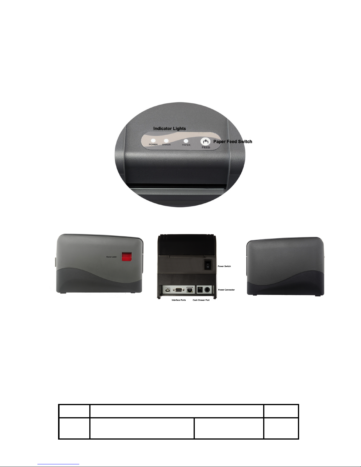
4. Printer Appearance
Page 15

OM9500F Technical Manual
Rev.
1.0
Document No.: 19B00271
Date: Jan 08, 2018
Page: 15
4.1 Switch and LED Functions
1. FEED Button
Press to feed paper manually; release to stop feeding.
2. Paper Status
When both Error and Paper LEDs are on, printer is out of paper.
When both Error and Paper LEDs are off, printer has paper.
When only the Paper LED is on, paper is low.
3. Power Condition
When Power LED is on, printer is turned on.
When Power LED is off, printer is turned off.
4. Error Indicator
The LED blinks when there is a paper out, cutter error, or print head overheat condition.
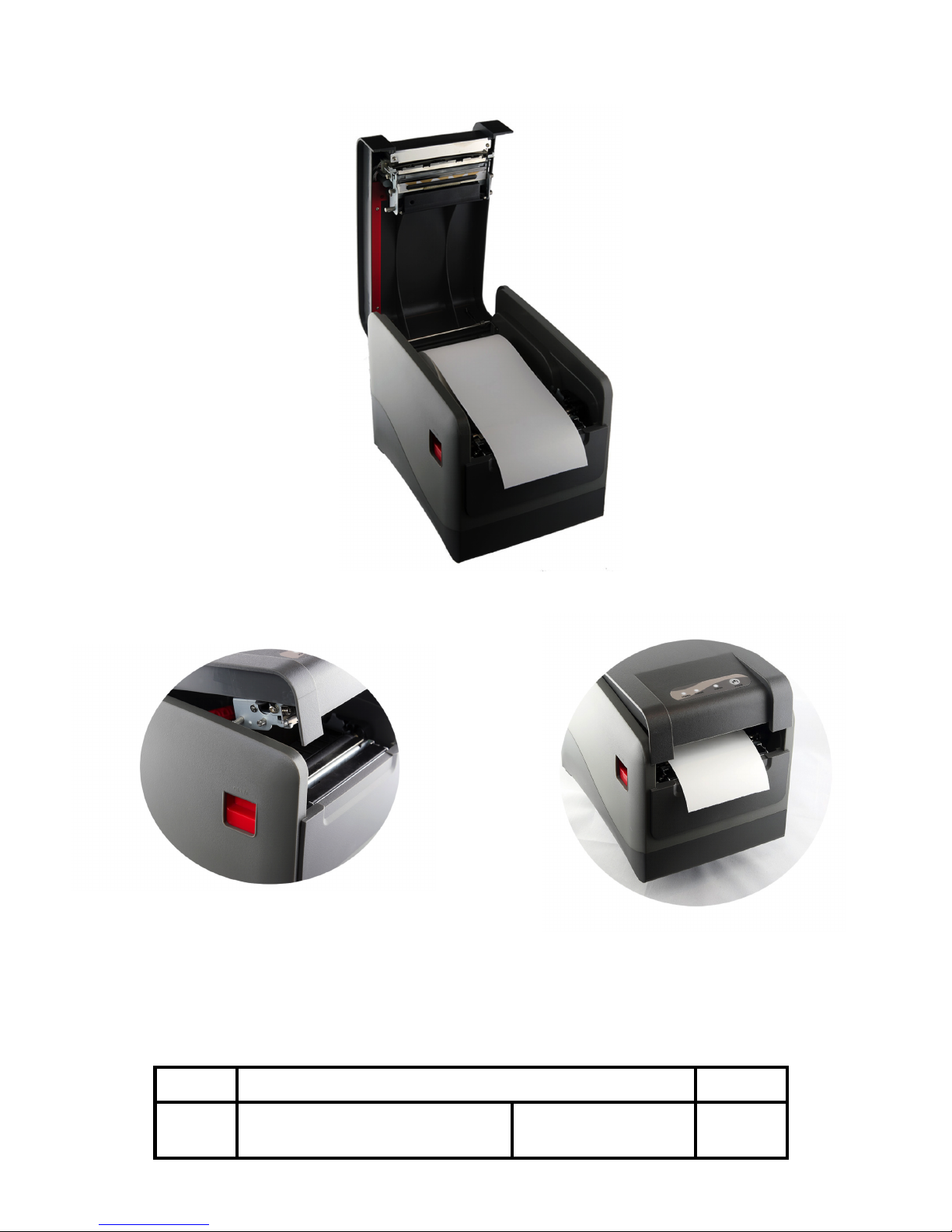
5. Paper Loading
Use a paper roll that meets the specifications below. Do not use paper rolls that are glued to the
core. Make sure data is not being transmitted to the printer while loading paper.
1. To open the paper cover press the latch located on the left side of the Printer, as
indicated in illustration 4.0 Printer Appearance.
2. Remove the old paper roll core.
3. Lift the paper cover. Please make sure no objects are dropped inside and avoid
touching any internal parts of the printer including the rubber roller with any sharp object.
4. Make sure the paper roll is curling up.
5. Pull the paper so that the leading edge of the roll goes at least two inches beyond the
printer tear bar.
6. Gently lower the printer paper cover and make sure it is closed tightly.
7. Press the FEED button to make sure the roll is properly loaded. If you notice any
wrinkles or creases on the edges of the paper try loading the paper again.
8. Tear the excess paper against the serrated edge.
9. To reorder paper, please use part number: TP-80-230.
Page 16
OM9500F Technical Manual
Rev.
1.0
Document No.: 19B00271
Date: Jan 08, 2018
Page: 16
Page 17
OM9500F Technical Manual
Rev.
1.0
Document No.: 19B00271
Date: Jan 08, 2018
Page: 17
6. Dip Switch
6.1 Setting the Dip Switch
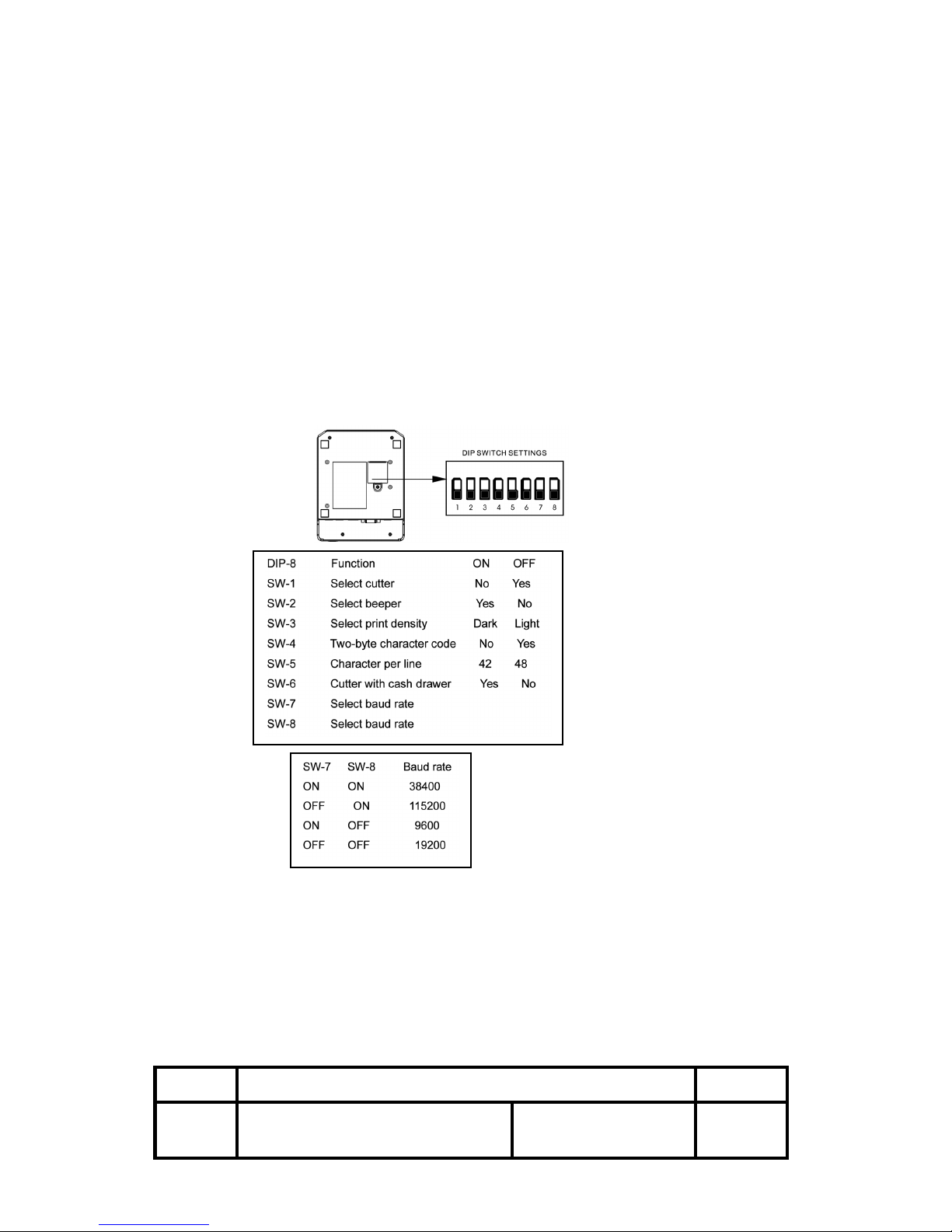
An 8 position DIP switch is located on the bottom of the printer unit. Gently turn the printer over
and use a small Philips screw driver to remove the cover. By changing the switch positions you
can modify the default setting for various functions such as cutter mode, character set, beeper,
printer speed etc.
NOTES: 1. To change the printer setting please make sure the power is turned off.
2. When changing the baud rate, make sure the host and printer baud rates match.
Page 18
OM9500F Technical Manual
Rev.
1.0
Document No.: 19B00271
Date: Jan 08, 2018
Page: 18
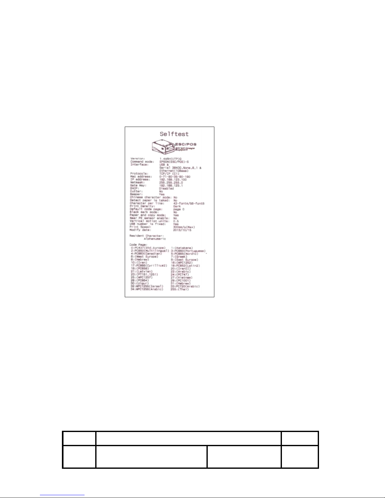
Self Test
You can perform a self test to determine the default settings and obtain the printer revision
number. First, make sure the printer is turned off and then while pressing the Paper Feed
button turn the printer on. The printer starts printing its factory setting.
Code Page Setting:
Refer to the Self Test page code details, for example:
For English: Select Page 0
For Russian: PC868
Chinese: Two Byte Character Code, SW-4 must be OFF
Page 19
OM9500F Technical Manual
Rev.
1.0
Document No.: 19B00271
Date: Jan 08, 2018
Page: 19
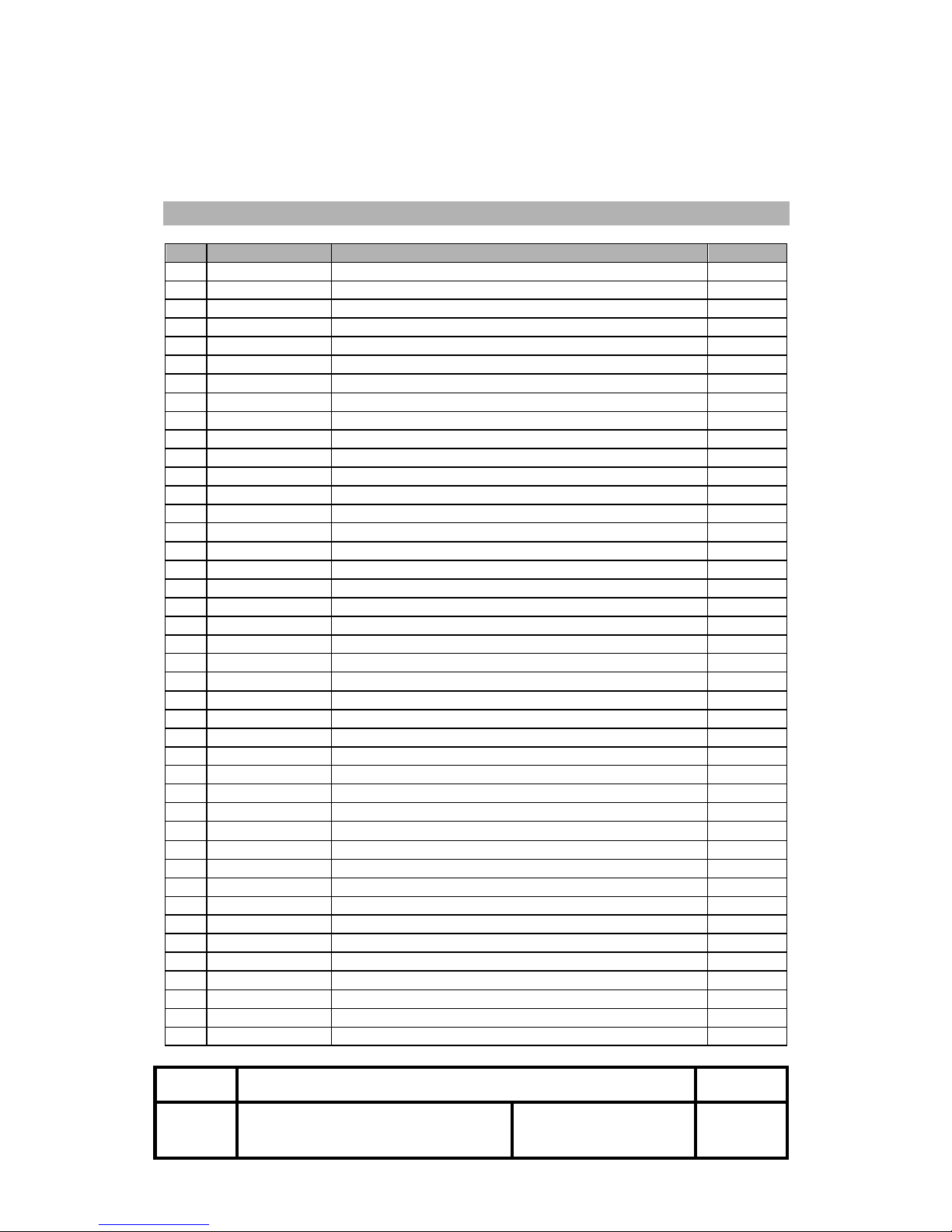
Control command summary
No.
Command
Function
1
HT
Horizontal tab
2
LF
Print and line feed
3
CR
Print and carriage return
4
FF
Print end position label to start printing
5
CAN
Cancel print data in page mode
6
DLE EOT
Real-time status transmission
7
DLE ENQ
Real-time request to printer
8
DLE DC4
Generate pulse at real-time
9
ESC FF
Print data in page mode
10
ESC SP
Set character right-side spacing
11
ESC !
Set print mode
12
ESC $
Select/cancel user-defined character set
13
ESC %
Define user-defined characters
14
ESC &
Turn underline mode on/off
15
ESC *
Set bit image mode
16
ESC -
Turn underline mode on/off
17
ESC 2
Set 1/6 inch line spacing
18
ESC 3
Set line spacing using minimum units
19
ESC =
Select peripheral device
20
ESC ?
Cancel user-defined characters
21
ESC @
Initialize printer
22
ESC D
Set horizontal tab positions
23
ESC E
Select emphasized mode
24
ESC G
Select double-strike mode
25
ESC J
Print end feed paper using minimum units
26
ESC L
Select page mode
27
ESC M
Select character font
28
ESC R
Select international character set
29
ESC S
Select standard mode
30
ESC T
Select print direction in page mode
31
ESC V
Set/cancel 90° cw rotated character
32
ESC W
Set printing area in page mode
33
ESC \
Set relative position
34
ESC a
Align position
35
ESC c 3
Select paper sensor(s) to output paper-end signals
36
ESC c 4
Select paper sensor(s) to stop printing
37
ESC c 5
Enable/disable panel buttons
38
ESC d
Print and feed paper n lines
39
ESC p
General pulse
40
ESC t
Select character code table
41
ESC {
Set/cancel upside-down character printing
42
GS !
Select character size
Page 20
OM9500F Technical Manual
Rev.
1.0
Document No.: 19B00271
Date: Jan 08, 2018
Page: 20
43
GS $
Set absolute vertical print position in page mode
44
GS *
Define downloaded bit image
45
GS /
Print down-loaded bit image
46
GS :
Start/end macro definition
47
GS B
Turn white/black reverse printing mode on/off
48
GS H
Select printing position of HRI characters
49
GS I
Transmit printer ID
50
GS L
Set left margin
51
GS P
Set horizontal and vertical motion units
52
GS V
Cut paper
53
GS W
Set printing area width
54
GS \
Set relative vertical print position in page mode
55
GS ^
Execute macro
56
GS a
Enable/disable Automatic Status Back(ASB)
57
GS b
Turn smoothing mode on/off
58
GS f
Select font for HRI characters
59
GS h
Set bar code height
60
GS k
Print bar code
61
GS r
Transmit status
62
GS v 0
Print raster bit image
63
GS w
Set bar code width
< Add >
1
ESC I
Full cut
2
ESC m
Partial cut
Page 21

OM9500F Technical Manual
Rev.
1.0
Document No.: 19B00271
Date: Jan 08, 2018
Page: 21
‘Command Descriptions
Command Notation
[Name] The name of the control command.
[Format] The code sequence.
In this description, < > H denotes hexadecimal numbers, < >denotes decimal
numbers and < > B denotes binary numbers.
[ ] k indicates the contents of the [ ] should be repeated k times.
[Range] The allowable range for the arguments.
[Description] Description of the command function.
[Notes] If necessary provides important information on setting and using the printer
command.
[Default] The default values for the commands.
[Reference] List related commands.
[Example] Example of using the commands.
The numbers denoted by <>H is hexadecimal.
The numbers denoted by <>B is binary.
Print Commands
Please see OMNIPrint Printer Control Command Set document for detailed
explanation of the command codes.
Page 22

OM9500F Technical Manual
Rev.
1.0
Document No.: 19B00271
Date: Jan 08, 2018
Page: 22
ELECTRONIC EMISSION NOTICES
FEDERAL COMMUNICATIONS COMMISSION (FCC) STATEMENT
This equipment has been tested and found to comply with the limits for a Class A
digital device, pursuant to Part 15 of the FCC Rules. These limits are designed to
provide reasonable protection against harmful interference when operated in a
commercial environment. This equipment generates, uses, and can radiate radio
frequency energy, and if not installed and used in accordance with the instructions,
may cause harmful interference to radio communications. However, there is no
guarantee that interference will not occur in a particular installation. If this equipment
does cause harmful interference to radio or television reception, which can be
determined by turning the equipment off and on, the user is encouraged to try to
correct the interference by one or more of the following measures:
§ Reorient or relocate the receiving antenna.
§ Increase the separation between the equipment and receiver.
§ Connect the equipment into an outlet on a circuit different from that to which the receiver is
connected.
§ Consult your authorized reseller or service representative for help.
Properly shielded and grounded cables and connectors must be used in order to meet
FCC emission limits. Proper cables and connectors are available from OMNIPRINT
INC. authorized dealers.
INDUSTRY CANADA CLASS A EMISSION COMPLIANCE STATEMENT
This Class A digital apparatus meets all the requirements of the Canadian Interference-
Causing Equipment Regulations.
Cet appareil numérique de la classe A respecte toutes les exigences du Règlement sur
le matériel brouilleur du Canada.
Page 23

OM9500F Technical Manual
Rev.
1.0
Document No.: 19B00271
Date: Jan 08, 2018
Page: 23
EUROPEAN UNION – EMISSION DIRECTIVE
This product is in conformity with the protection requirements of EU Council Low
Voltage Directive 73/23/EEC and Electromagnetic Compatibility Directive 89/336/ECC
on the approximation of the laws of the member states of the EEC Commission.
OMNIPRINT INC. cannot accept responsibility for any failure to satisfy the protection
requirements resulting from a non-recommended modification of the product.
This product has been tested and found to comply with the limits for Class A
Information Technology Equipment according to CISPR 22 / European Standard EN
55022. In a domestic environment this product may cause radio interference in
which case the user may be required to take adequate measures
 Loading...