

Page 1
OPS-UM-001-C User Manual OmniPreSense Corporation 1
OPS242 User Manual
OmniPreSense OPS242 short range radar sensor has an easy to use API to control the output of the sensor.
Simple commands can be used to configure the operation and output information provided by the sensor.
Default settings are noted below. Upon powering on the module, the default settings are used.
Installation Instructions
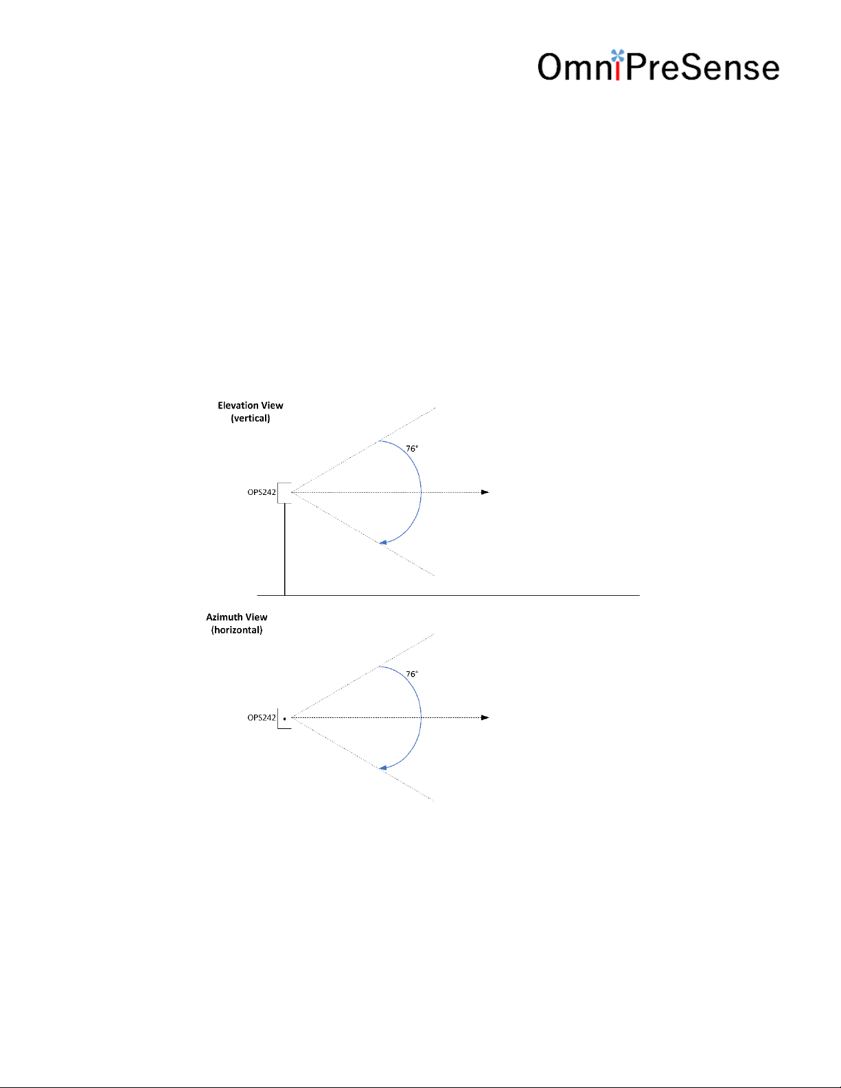
The OPS242 provides a complete radar module on a single board. The coverage area or field of view (FOV)
for the OPS242 is 76 in the azimuth (horizontal) and elevation (vertical). Install the OPS242 facing the
direction of the FOV to be covered.
Figure 1. OPS242 Beamwidth
The OPS242 can generally can be placed behind most any material (plastic, glass, wood, etc.) depending
on thickness. Typical applications will use plastics such as ABS or PVC at 3 or 6mm thickness. Some
materials will block the signal and the OPS242 should not be placed behind these. Examples of these are
metal, concrete or brick.
Page 2
OPS-UM-001-C User Manual OmniPreSense Corporation 2
Terminal Control
A simple Command Terminal can be used to control the sensor operation with the API commands.
Examples of simple but very useful Command Terminals are Tera Terminal and PuTTY. Both are free, open
source terminal tools for the PC/Mac which can easily connect to a serial port and accept data over USB
from the OminPreSense sensor.
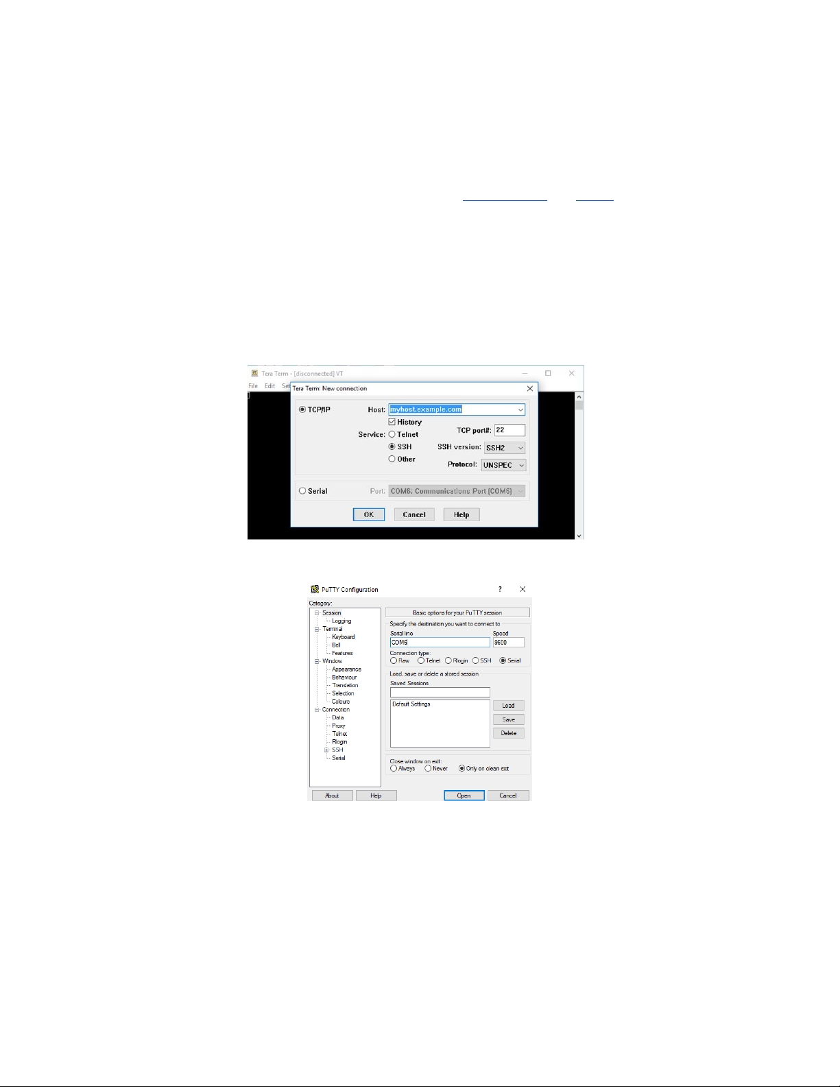
To begin using the OmniPreSense module, first download Tera Terminal or PuTTY onto your PC/Mac. With
the OmniPreSense sensor plugged into the USB port of your PC/Mac, start Tera Terminal or PuTTY. A
configuration window such as in Figure 2 or Figure 3 will appear. TeraTerm can detect the active COM
port (greyed out to right of Serial button if TCP/IP is selected). Select the Serial button and press OK. For
PuTTY, you’ll need to know which COM port is used, set its value, select the Serial button, and Open.
Figure 2. Tera Term Startup Menu
Figure 3. PuTTY Startup Menu
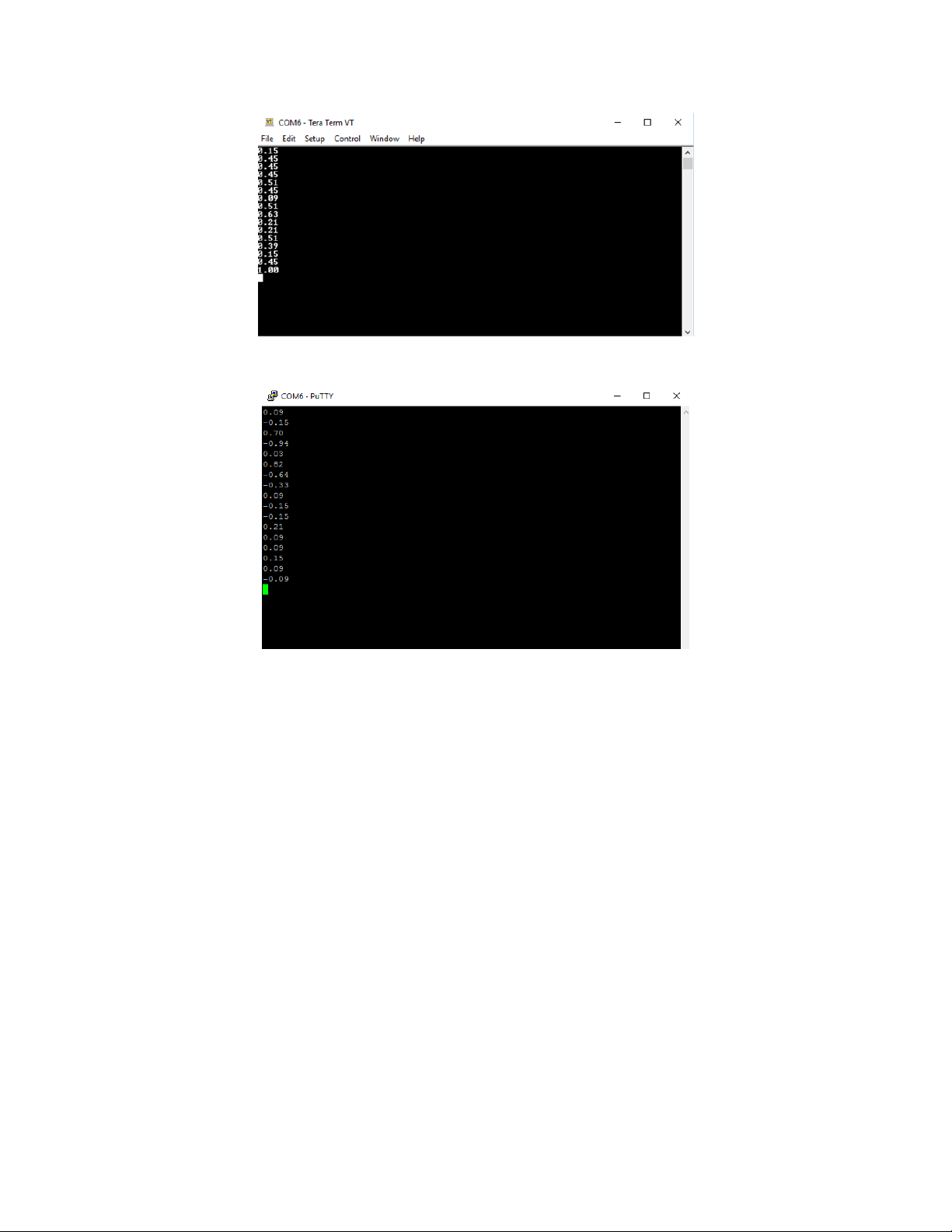
Once connected, the data reported by the sensor will start streaming to the terminal when an object in
motion appears. The default settings are shown in Table 1. If there is no object moving in front of the
module, no data is reported or streamed to the terminal. A simple wave of the hand will show data like
that shown in Figure 4. Any of the API commands can now be executed to change the output data or
query the configuration.
Page 3
OPS-UM-001-C User Manual OmniPreSense Corporation 3
Figure 4. Streaming Data with Tera Term
Figure 5. Streaming Data with PuTTY
Page 4

OPS-UM-001-C User Manual OmniPreSense Corporation 4
Default Settings
The default settings of the sensor are set to provide solid performance over a wide range of applications.
Upon power-up the default settings are used, and operation begins. Future updates will allow the module
to retain the settings of the sensor from the last operation. The default settings are listed in Table 1.
Table 1. Default Settings
API Command
API Command
Default Value
Output Units
UM
m/s
Data Accuracy
F2 2 Sample Rate
SX
10,000
Sample Buffer Size
S>
1024
Reported Speed Filter
R=n
Off
Reported Direction Filter
R|
Off
Quash Noise
QQ
On
JSON Output
Oj
Off
LED Control
OL
On
Magnitude Report
Om
Off
Number Reports
On
1
Raw Data Output
Or
Off
Speed Report
OS
On
Time Report
Ot
Off
Module Power
PA
Active
Operating Range
The maximum speed reported is determined by the Sampling Frequency. For slow moving objects, a
sample rate of 5,000 (SV command) is perfectly fine. The default setting of 10,000 (SX command) provides
a detectable speed of up to 31.1 m/s (69.5 mph) while 20,000 (S2 command) provides up to 62.2 m/s
(139.1 mph). The accuracy of the reported speed increases as the sample frequency goes down. The
range of values is summarized in Table 2.
Table 2. Maximum Operating Speeds
Sample
Frequency
API
Command
Maximum
Speed (m/s)
Maximum
Speed (mph)
Accuracy*
(m/s)
Accuracy*
(mph)
1,000
SI
3.1
7.0
0.006
0.014
5,000
SV
15.5
34.8
0.030
0.068
10,000
SX
31.1
69.5
0.061
0.136
20,000
S2
62.2
139.1
0.121
0.272
50,000
SL
155.4
347.7
0.304
0.679
100,000
SC
310.8
695.4
0.608
1.358
* 1024 buffer size, 512 buffer size accuracy will be twice these values
Page 5

OPS-UM-001-C User Manual OmniPreSense Corporation 5
API Commands
The following are the API commands supported by the OPS242-A. These commands can be sent by typing
into the command terminal to change settings on the module or control its operation. The commands
provided include simple queries to fetch information about the sensor and it settings or write commands
which control or change the operation of the sensor.
Module Information – returns information about the sensor and it’s report setting.
Command
Name
R/W
Value
??
Module Information
Read
{"Product":"OMPS242A"}
{"Version":"1.2.0"}
{"SamplingRate":10000, "resolution":0.0607}
{"Clock":"20054"}
{"PowerMode":"Continuous"}
Sensor Part Number – returns sensor model number consisting of OmniPreSense ACPI vendor ID and
part number.
Command
Name
R/W
Value
?P
Sensor Part Number
Read
{"Product":"OMPS242A"}
Firmware Version – returns current firmware version of the sensor. Firmware version consists of a
major revision, minor revision, and patch revision in the form of xx.yy.zz.
Command
Name
R/W
Value
?V
Firmware Version Number
Read
{"Version":"1.2.0"}
?B
Firmware Build Number
Read
{"Build":"20180705_1500"}
Speed Output Units – read or set the units for the velocity output. Units supported include m/s
(default), cm/s, ft/s, km/hr, and miles per hour.
Command
Name
R/W
Value
U?
Current Velocity Units
Read
{"Units":"m-per-sec"}
UC
Centimeters per second
Write
{"Units":"cm-per-sec"}
UF
Feet per second
Write
{"Units":"ft-per-sec"}
UK
Kilometers per hour
Write
{"Units":"km-per-hr"}
UM
Meters per second
Write
{"Units":"m-per-sec"}
US
Miles per hour
Write
{"Units":"mph"}
Page 6

OPS-UM-001-C User Manual OmniPreSense Corporation 6
Data Precision – set the number of digits for the data reported.
Command
Name
R/W
Value
Fn
Decimal Places
Write
Set n to the number of decimal places to be
reported. For example, setting to F2 will
report 2 decimal places (ex. 10.35). F0 will
provide the integer value only. Valid values of
n are 0-5.
Sampling Rate/Buffer Size – set these values to control the sample rate of the sensor. This setting
influences the output data and the rate at which the data is reported. The buffer size influences the report
rate and accuracy. A buffer size of 512 will have a report rate between 5-30Hz. The accuracy becomes
worse by a factor of two with a 512-buffer size versus 1024 (Figure 6).
Command
Name
R/W
Value
SI
1K samples/second
Write SV
5K samples/second
Write
SX or S1
10K samples/second
Write S2
20K samples/second
Write SL
50K samples/second
Write SC
100K samples/second
Write S>
1024 buffer size
Write
1024 samples are collected before processing
S<
512 buffer size
Write
512 samples are collected before processing
Figure 6. Buffer Size versus Accuracy
0.0
0.2
0.4
0.6
0.8
1.0
1.2
1.4
1,000 5,000 10,000 20,000 50,000 100,000
Accuracy (m/s)
Sampling Rate
512 Buffer
1024 Buffer
Page 7

OPS-UM-001-C User Manual OmniPreSense Corporation 7
Reported Speed/Direction Filter – use these settings to set the minimum value or direction to report.
Reported speed can be used to set the sensitivity level of detection. Any values below the number n will
not be reported. This command requires a return () after the number. Direction filter allows reporting
only a single direction or both.
Command
Name
R/W
Value
R>n
Reported Speed Filter
Write
n is any number upon which no detected
speeds below that number will be reported
R+
Inbound Only Direction
Write
Only reports inbound direction
R-
Outbound Only Direction
Write
Only reports outbound direction
R|
Clear Direction Control
Write
Reports both directions
Frequency Control – use this setting to set the desired transmit frequency. Set n to a positive or negative
number between +/4 to set the frequency. T=0 is the default setting for 24.125GHz. Each increment steps
approximately 18MHz. The programming steps are limited to 24.089 through 24.161GHz operation.
Depending on the spread between the current frequency and the newly set frequency, there may be a
long settling time on the order of 5-10 seconds or longer based on the size of the jump in values. Writing
?F will provide the current transmitter output frequency.
Command
Name
R/W
Value
T=n
Frequency Setting
Write
T=0 is the default setting for 24.125GHz. n = 2, -1, 0, 1, or 2
?F
Frequency Output
Read
?F returns the output frequency of the
transmitter in GHz.
Page 8

OPS-UM-001-C User Manual OmniPreSense Corporation 8
Data Output – set to control the data which is output.
Command
Name
R/W
Value
OF
FFT Output On
Write
Results from the FFT processing of each buffer
will be sent. Each buffer is 1024 samples.
Data is output with json output format.
Of
FFT Output Off
Write
Turns off FFT output.
OJ
json Mode On
Write
‘Turns on output to format data in json
format. An example would output:
{"speed":0.58, "direction":"inbound",
“time”:105, :tick”:135}
Oj
json Mode Off
Write
Turns off json output mode.
OR
Raw ADC Output On
Write
I and Q output buffers from the ADC will be
sent. Data will alternate between outputting
the I buffer and then Q buffer.
Or
Raw ADC Output Off
Write
Turns off output of the I and Q buffers.
OL
LED Control
Write
Turn the LEDs on (OL) or off (Ol). Turning off
the LED’s can save approximately 10mA of
current consumption.
On
Number Reports
Write
Define how many reports to provide. n is a
number between 1 and 9. The number n
holds for time, magnitude, and speed.
OM
Magnitude Report
Write
Turn on reporting of the magnitude associated
with the speed. The magnitude is a measure
of the size, distance, and reflectivity of the
object detected. Type Om to turn magnitude
off. When turned on, magnitude information
comes before speed information.
OS
Speed Report
Write
Turn speed reporting on or off. Default
operation speed is reported. Use Os to turn it
off and OS to turn it back on.
OT
Time Report
Write
Turn the time report on. Time is reported as
the seconds and milliseconds since the last
reboot or power on. For example, 137.429,
3.6 is read as 137 seconds and 429
milliseconds with a speed of 3.6 m/s. If
magnitude is turned on, the data is provided
as time, magnitude, speed.
Page 9

OPS-UM-001-C User Manual OmniPreSense Corporation 9
Timing Report – set to control the reporting of the time. The time is measured in seconds/milliseconds
from power on of the module. Use the OJ command to report the time in seconds and milliseconds along
with the speed and direction information (or direction can be turned off). When the module is put in low
power state, the clock will continue counting. If you wish for the module to provide “the real time”, then
set it to “the Unix time” (see wikipedia.org/wiki/Unix_time).
Command
Name
R/W
Value
C?
Query Time
Read
Ex. {“Clock”:”50”} reports 50 seconds since
power on.
C=n
Set Time
Write
Reset the clock start time. For example, n = 10
will start the clock at 10 seconds and then
continue counting.
Module/Transmit Power – set to control the operating mode (PA, PI, PP) or the transmit power. The
typical maximum transmit power is 9 dB. Reducing the transmit power does not reduce the overall
power consumption of the module. Note that the detection range will decrease with decreased
transmit power.
Command
Name
R/W
Value
PA
Active Power Mode
Write
Normal operating mode.
PI
Idle Power Mode
Write
No activity, waits for Active Power command.
The RF is powered down for further power
savings.
PP
Single Shot Mode
Write
Use this mode to capture and process a single
buffer of data. The module will stay in PP
mode until either a PA or PI command is given.
While in PP mode, the RF device is powered
off to save power.
P7 or PN
Transmit Power Control or
Min Power
Write
Transmit is set at -9 dB below max power.
P6
Transmit Power Control
Write
Transmit is set at -6 dB below max power.
P5
Transmit Power Control
Write
Transmit is set at -4 dB below max power.
P4
Transmit Power Control
Write
Transmit is set at -2.5 dB below max power.
P3 or PD
Transmit Power Control or
Mid Power
Write
Transmit is set at -1.4 dB below max power.
PD has additional “overdrive” of 0.2 dB when
utilized.
P2
Transmit Power Control
Write
Transmit is set at -0.8 dB below max power.
P1
Transmit Power Control
Write
Transmit is set at -0.4 dB below max power.
P0 or PX
Transmit Power Control or
Max Power
Write
Transmit power is set at its maximum value
with maximum range. PX has additional
“overdrive” of 0.2 dB when utilized.
Duty Cycle Control – set to control the duty cycle operation. The time set is the amount of time the
module will sleep between transmit/receive pulses and processing. During the sleep time the orange LED
will be on. For settings longer than 1 second, the RF will be powered off to save power. In this manner,
lower power operation may be achieved.
Page 10

OPS-UM-001-C User Manual OmniPreSense Corporation 10
Command
Name
R/W
Value
Z0
Sleep 0 Second
Write
Use to set back to normal operation.
ZI
Sleep 1 Second
Write ZV
Sleep 5 seconds
Write
ZX or Z1
Sleep 10 seconds
Write ZL
Sleep 50 seconds
Write ZC
Sleep 100 seconds
Write Z2
Sleep 200 seconds
Write
Z=n
Set Sleep Time
Write
Set the amount of time to sleep between data
processing. Ex., n = 5 would set the module to
sleep for 5 seconds (RF powered off) between
a transmit/receive pulse and processing.
Squelch Control – provides control over the sensitivity of the module to detect moving objects. Low
numbers are most sensitive, high numbers are least sensitive.
Command
Name
R/W
Value
QI
Squelch Control - 100
Write
Highest sensitivity setting.
QV
Squelch Control - 500
Write QX
Squelch Control – 1,000
Write QL
Squelch Control – 5,000
Write QC
Squelch Control – 10,000
Write
Qn
Squelch Control
Write
Set n to the desired squelch number x 1000.
For example, setting to Q2 will set the value to
2000. Valid values of n are 0-9. 0 provides no
squelch control and all data will be reported.
Q=n
Squelch Control
Write
n = any arbitrary number between 1 and 4
billion.
QQ
Quash On
Write
Quash filters out the lowest frequency
components around DC.
Qq
Quash Off
Write
Turns quash off.
Debug Modes – provides debug information about the module.
Command
Name
R/W
Value
DR/Dr
Red LED
Write
DR to turn on red LED, Dr to turn off.
DY/Dy
Yellow LED
Write
DY to turn on yellow LED, Dy to turn off.
Page 11

OPS-UM-001-C User Manual OmniPreSense Corporation 11
FCC 15B Statement
This equipment has been tested and found to comply with the limits for a Class B digital device, pursuant
to part 15 of the FCC Rules. These limits are designed to provide reasonable protection against harmful
interference in a residential installation. This equipment generates, uses and can radiate radio frequency
energy and, if not installed and used in accordance with the instructions, may cause harmful interference
to radio communications. However, there is no guarantee that interference will not occur in a particular
installation. If this equipment does cause harmful interference to radio or television reception, which can
be determined by turning the equipment off and on, the user is encouraged to try to correct the
interference by one or more of the following measures:
—Reorient or relocate the receiving antenna.
—Increase the separation between the equipment and receiver.
—Connect the equipment into an outlet on a circuit different from that to which the receiver is connected.
—Consult the dealer or an experienced radio/TV technician for help.
FCC 15C Statement
This device complies with Part 15 of the FCC Rules. Operation is subject to the following two conditions:
(1) this device may not cause interference, and (2) this device must accept any interference, including
interference that may cause undesired operation of the device.
FCC RF Exposure Statement
This transmitter must be installed to provide a separation distance of at least 20cm from all persons and
must not be co-located or operating in conjunction with any other antenna or transmitter. End-users must
be provided with transmitter operation conditions for satisfying RF exposure compliance.
IC Statement (English and French):
This device complies with ISED Canada license-exempt RSS standard(s). Operation is subject to the
following two conditions: (1) this device may not cause interference, and (2) this device must accept any
interference, including interference that may cause undesired operation of the device.
Le présent appareil est conforme aux CNR d'ISED Canada applicables aux appareils radio exempts de
licence. L'exploitation est autorisée aux deux conditions suivantes: (1) l'appareil ne doit pas produire de
brouillage, et (2) l'utilisateur de l'appareil doit accepter tout brouillage radio électrique subi, même si le
brouillage est susceptible d'en comprom-ettre le fonctionnement.
Page 12

OPS-UM-001-C User Manual OmniPreSense Corporation 12
Non-modification Statement
OmniPresense Corporation has not approved any changes or modifications to this device by the user.
Any changes or modifications could void the user’s authority to operate the equipment.
The final product containing the modular transmitter must be labeled with the following statement:
“Contains FCC ID: 2ALLL242A”
“Contains IC: 24107-08600250004”
Page 13

OPS-UM-001-C User Manual OmniPreSense Corporation 13
Revision History
Version
Date
Description
A
July 9, 2018
Initial release.
B
August 10, 2018
FCC language added.
C
August 27, 2018
Correction to frequency channels.
 Loading...