

OmniPower OHY1P4805 User Manual

1. Introduction
USER MANUAL
V3.0
5kW Hybrid Inverter
OHY1P4805

1. Introduction
Table of Contents
1. Introduction ................................................................................................... 1
2. Important Safety Warning ............................................................................. 2
3. Unpacking & Overview ................................................................................. 4
4. Installation ..................................................................................................... 5
5. Grid (Utility) Connection ............................................................................... 7
6. PV Module (DC) Connection ........................................................................ 9
7. Battery Connection .....................................................................................13
8. Load (AC Output) Connection ....................................................................14
9. EMS Connection .........................................................................................16
10. Generator connection .................................................................................17
11. Communication ...........................................................................................18
12. Dry Contact Signal ......................................................................................19
13. Relay Control Port ......................................................................................21
14. Application with Energy Meter ....................................................................23
15. Commissioning ...........................................................................................24
16. Initial Setup .................................................................................................25
17. Operation ....................................................................................................37
18. Charging Management ...............................................................................47
19. Maintenance & Cleaning ............................................................................49
20. Trouble Shooting ........................................................................................50
21. Specifications ..............................................................................................53
22. Limited Product Warranty ...........................................................................55
1. Introduction
1 www.sinetech.co.za
1. Introduction
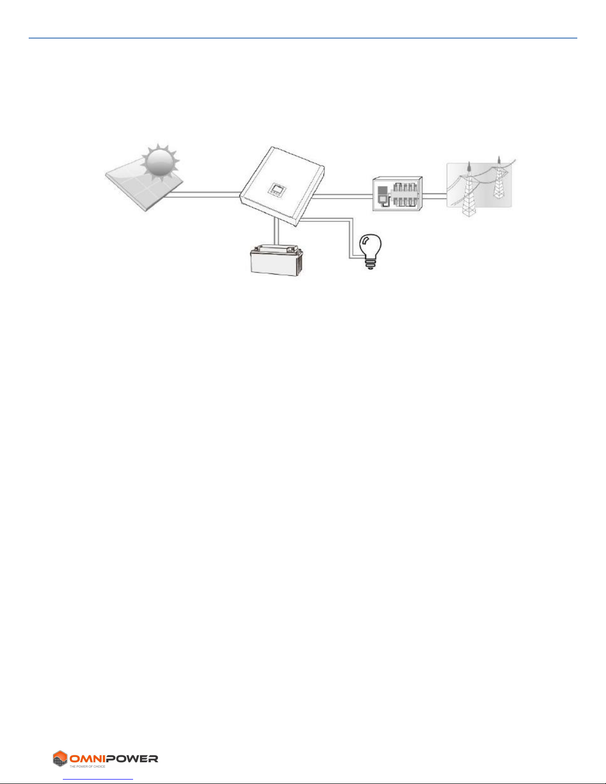
This hybrid PV inverter can provide power to connected loads by utilizing PV power,
utility power and battery power.
Figure 1 Basic hybrid PV System Overview
Depending on different power situations, this hybrid inverter is designed to generate
continuous power from PV solar modules (solar panels), battery, and the utility. When
MPP input voltage of PV modules is within acceptable range (see specification for the
details), this inverter is able to generate power to feed the grid (utility) and charge
battery. Do not connect the positive or negative terminal of the solar panel to the
ground. See Figure 1 for a simple diagram of a typical solar system with this hybrid
inverter.
Note: As per EEG standard, every inverter sold to a German area is not allowed to
charge battery from utility. The relevant function is automatically disabled by the
software.
PV modules
Battery
Hybrid inverter
Distribution Board
Electricity grid
Load
2. Important Safety Warning
2 www.sinetech.co.za
2. Important Safety Warning
Before using the inverter, please read all instructions and cautionary
markings on the unit and this manual. Store the manual where it can be
accessed easily.
This manual is for qualified personnel. The tasks described in this manual may be
performed by qualified personnel only.
General Precaution-
WARNING! Before installing and using this inverter, read all instructions and cautionary
markings on the inverter and all appropriate sections of this guide.
WARNING! Normally grounded conductors may be disconnected and energized when a
ground fault is indicated.
WARNING! This inverter is heavy. It should be lifted by at least two persons.
CAUTION! Authorized service personnel should reduce the risk of electrical shock by
disconnecting AC, DC and battery power from the inverter before attempting any
maintenance or cleaning or working on any circuits connected to the inverter. Turning off
controls will not reduce this risk. Internal capacitors can remain charged for 5 minutes
after disconnecting all sources of power.
CAUTION! Do not disassemble this inverter yourself. It contains no user-serviceable
parts. Attempting to service this inverter yourself may cause a risk of electrical shock or
fire and will void the manufacturer’s warranty.
CAUTION! To avoid risk of fire and electric shock, make sure that existing wiring is in
good condition and that the wire is not undersized. Do not operate the Inverter with
damaged or substandard wiring.
Conventions used:
WARNING! Warnings identify conditions or practices that could result in personal injury.
CAUTION! Caution identifies conditions or practices that could result in damage to the
unit and / or other equipment connected.
2. Important Safety Warning
3 www.sinetech.co.za
CAUTION! Under high temperature environment, the cover of this inverter could be hot
enough to cause skin burns if accidentally touched. Ensure that this inverter is away
from normal traffic areas.
CAUTION! Use only recommended accessories/instruments from installer. Unsuitable
tools may cause a risk of fire, electric shock, or injury to persons.
CAUTION! To reduce risk of fire hazard, do not cover or obstruct the cooling fan.
CAUTION! Do not operate the Inverter if it has, been knocked, dropped, or damaged in
any way. If the Inverter is damaged, please contact your distributor.
CAUTION! AC breaker, DC switch and Battery circuit breaker are used as disconnect
devices and these disconnect devices shall be easily accessible.
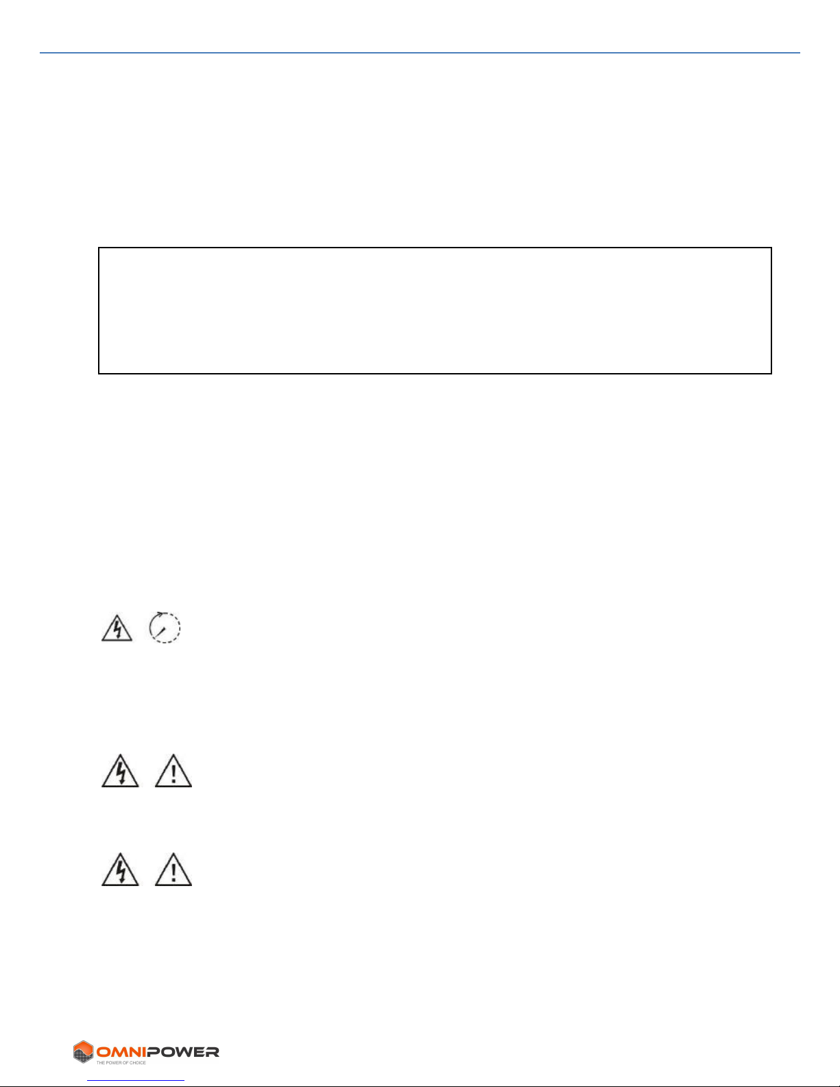
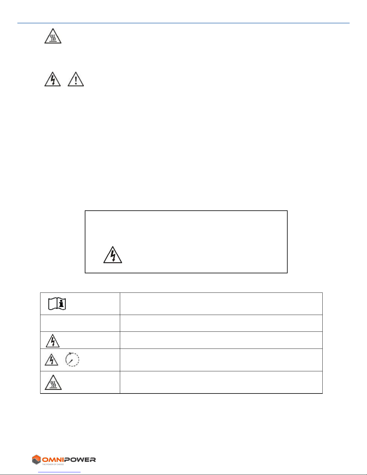
Symbols used in Equipment Markings
Refer to the operating instructions
Caution! Risk of danger
Caution! Risk of electric shock
Caution! Risk of electric shock. Stored energy. Allow discharge
time of 5 minutes.
Caution! Hot surface
Before working on this circuit
- Isolate inverter/Uninterruptible Power Supply (UPS)
- Then check for Hazardous Voltage between all
terminals including the protective earth.
3. Unpacking & Overview
4 www.sinetech.co.za
3. Unpacking & Overview
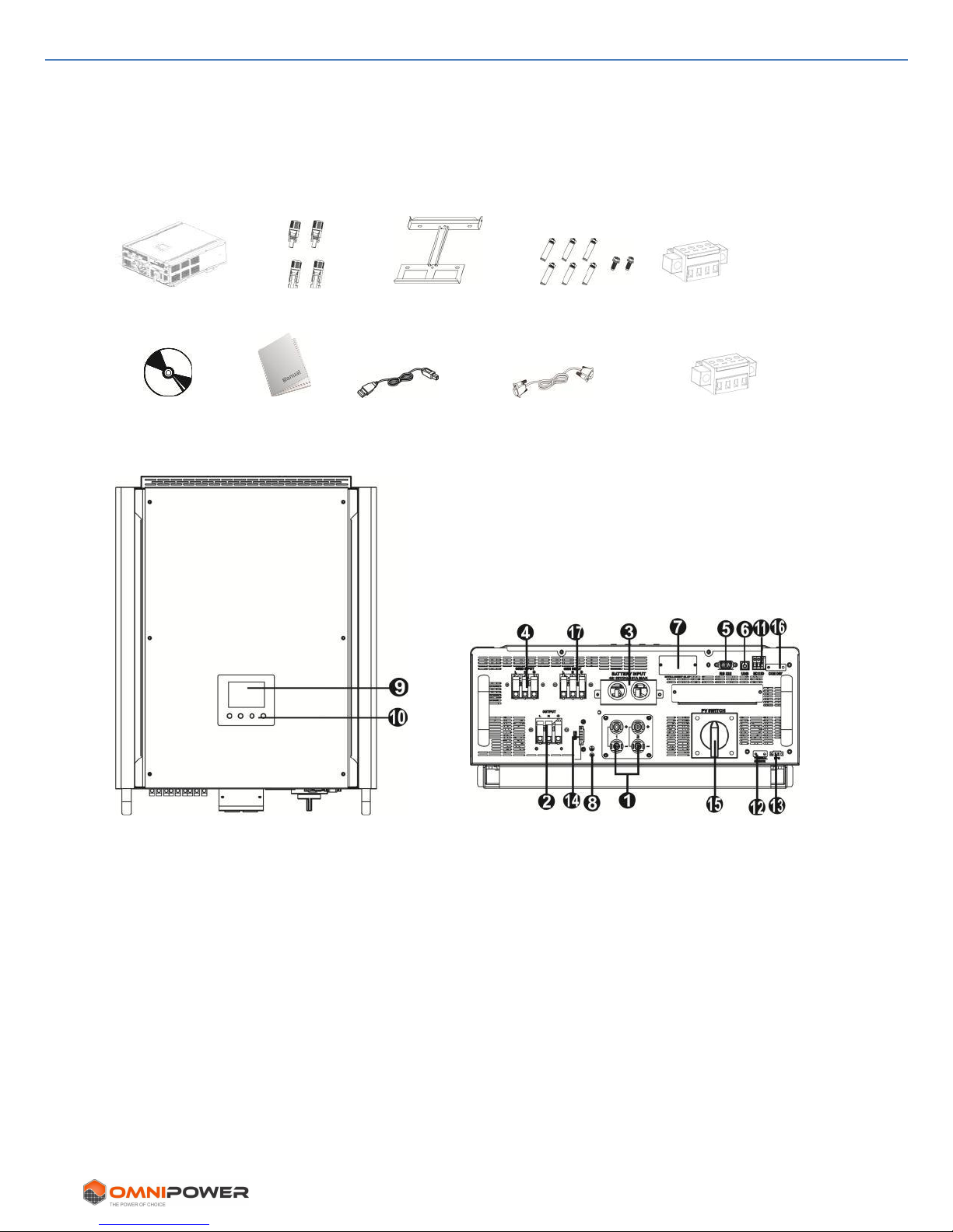
3-1. Packing List
Before installation, please inspect the unit. Ensure that nothing inside the package is
damaged. You should have received the following items inside of the package:
Inverter unit PV connectors Mounting plate Fixing screws EMS port
Software CD Manual USB cable RS-232 cable Relay control port
3-2. Product Overview
1) PV connectors
2) AC output connection (Load)
3) Battery connection
4) AC Grid connection
5) RS-232 communication port
6) USB communication port
7) Intelligent slot
8) Grounding
9) LCD display panel (Please check
section 10 for detailed LCD
operation)
10) Control buttons
11) Dry contacts
12) Battery temperature sensor
13) Emergency Power Off (EPO)
14) EMS (UPS) port
15) PV DC Switch
16) Relay control port
17) Generator connection

4. Installation
5 www.sinetech.co.za
4. Installation
4-1. Selecting Mounting Location
Consider the following points before selecting where to install:
• Do not mount the inverter on flammable materials.
• Mount on a solid surface
• This inverter can emit noises during operation which may be perceived as a nuisance
in a living area.
• Install this inverter at eye level in order to allow the LCD display to be read at all
times.
• For proper air circulation to dissipate heat, allow a clearance of ± 20 cm to the side
and ± 50 cm above and below the unit.
• Dusty conditions on the unit may impair the performance of this inverter.
• The ambient temperature should be between 0°C and 40°C and relative humidity
should be between 5% and 85% to ensure optimal operation.
• The installation position is to be vertical.
• For proper operation of this inverter, please use appropriate cables for grid
connection.
• The pollution degree of the inverter is PD2. Select an appropriate mounting location.
Install the solar inverter in a protected area that is dry, free of excessive dust and
has adequate air flow. Do NOT operate it where the temperature and humidity is
beyond the specific limits. (Please check the specs for the limitations.)
• Installation position should not impede access to the connections.
• This inverter is designed with a rating of IP20 for indoor applications only.
• Regularly clean the fan filter.
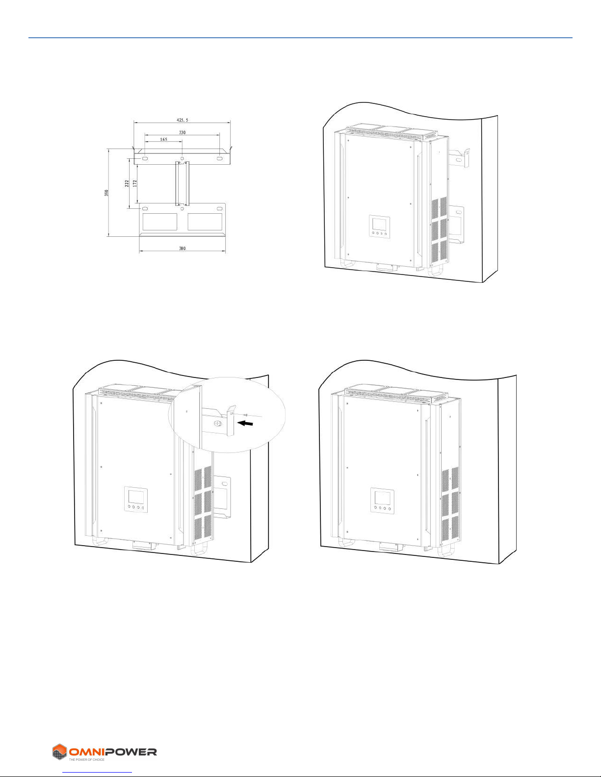
4-2. Mounting Unit
Wall mounting should be implemented with the proper bolts. The device should be
bolted on securely.
The inverter can only be used in an ENCLOSED ELECTRICAL OPERATING AREA. Only
service personnel should enter this area.
WARNING!! Remember that this inverter is heavy! Please be careful when lifting.
WARNING!! FIRE HAZARD.
MOUNT ON CONCRETE OR OTHER NON-COMBUSTIBLE SURFACES ONLY.
4. Installation
6 www.sinetech.co.za
1. Drill six holes at the marked
locations for six screws supplied.
The tightening torque is 35 N.m.
2. Raise the inverter and place it over the
mounting plate.
3. Fix the inverter in position with the
two screws (M4*12) supplied. Top
two sides of the inverter.
4. Check if the inverter is firmly secured.
5. Grid (Utility) Connection
7 www.sinetech.co.za
5. Grid (Utility) Connection
5-1. Preparation
Before connecting to AC utility, please install a separate AC circuit breaker between
inverter and AC utility. This will ensure the inverter can be safely disconnected during
maintenance and is fully isolated from the AC input.
NOTE1: Although this inverter is equipped with a 250VAC/40A fuse, install a separate
circuit breaker for safety. Use a 250VAC/40A circuit breaker between inverter and AC
utility.
NOTE2: The overvoltage category of the AC input is III. It should be connected to a
power distribution board.
WARNING! It's very important for system safety and efficient operation to use
appropriate cable for grid (utility) connection. To reduce risk of injury, please use the
proper recommended cable size as below. Suggested cable requirement for AC wire:
Model
5KW
Nominal Grid Voltage
230VAC
Conductor cross-section (mm2)
10 mm2
AWG no.
7
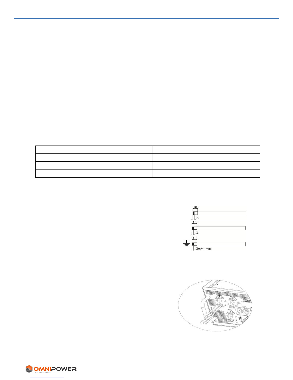
5-2. Connecting to the AC Utility
Step 1: Check the grid voltage and frequency with a voltmeter. It should be the same as
“VAC” value on the product label.
Step 2: Turn off the circuit breaker.
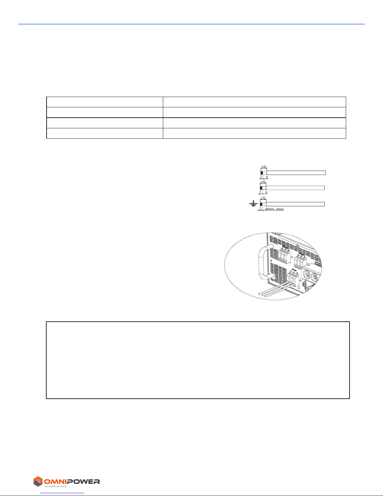
Step 3: Remove insulation sleeve 10 mm on all three
conductors. Shorten phase and neutral conductors to
3 mm. Refer to chart 1.
Step 4: Connect wires according to polarities
indicated on terminal block. Be sure to connect PE
protective conductor ( ) first.
L→LINE (brown or black)
→Ground (yellow-green)
N→Neutral (blue)
Step 5: Make sure the wires are securely connected.
The tightening torque is 0.8 N.m.
Chart 2
L
N
Chart 1
5. Grid (Utility) Connection
8 www.sinetech.co.za
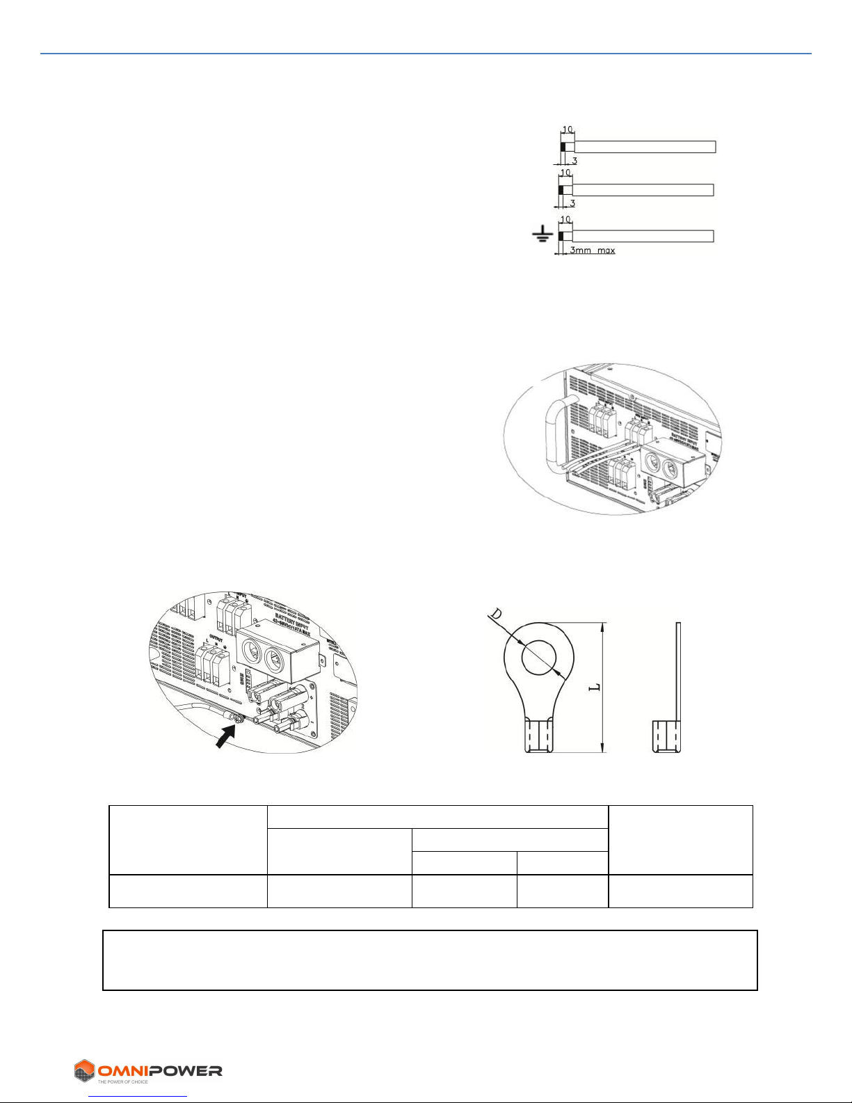
5-3. Connecting to the Generator
Step 1: Check the generator voltage and frequency with a voltmeter. It should be the
same as “VAC” value on the product label.
Step 2: Turn off the circuit breaker.
Step 3: Remove insulation sleeve 10 mm from all
three conductors. Shorten phase and neutral
conductors to 3 mm. Refer to chart 1.
Step 4: Connect wires according to polarities
indicated on terminal block. Be sure to connect PE protective conductor ( ) first.
L→LINE (brown or black)
→Ground (yellow-green)
N→Neutral (blue)
Step 5: Make sure the wires are securely connected.
The tightening torque is 0.8 N.m.
Note: For safe operation, use one more wires with ring terminal to connect earth.
Refer to Chart 3.
Chart 3
Recommended wire and terminal size:
Wire Size
Ring Terminal
Torque value
Cable mm2
Dimensions
D (mm)
L (mm)
7 AWG
10
4.3
21.8
1.2 to 2 Nm
CAUTION: To prevent risk of electric shock, ensure the ground wire is properly
earthed before operating this hybrid inverter, regardless if grid is connected or not.
Chart 2
Ring terminal:
L
N
Chart 1
6. PV Module (DC) Connection
9 www.sinetech.co.za
6. PV Module (DC) Connection
CAUTION: Before connecting to PV modules, please install a DC circuit breaker/fuse
separately between inverter and PV modules.
NOTE1: Use a 1000VDC/10A circuit breaker / fuse.
NOTE2: The overvoltage category of the PV input is II.
Please follow below steps to implement PV module connection:
Step 1: Check the output voltage of the PV array. The acceptable input voltage range of
the inverter is 250VDC - 900VDC. This system is designed for two PV array strings.
Make sure that the maximum current load of each PV input is below 10A.
Step 2: Open the circuit breaker/fuse and switch off the DC switch.
Step 3: Assemble provided PV connectors.
Components and Tools for PV connectors:
Female connector housing
Female terminal
Male connector housing
CAUTION: Exceeding the maximum input voltage can destroy the unit!!
Check the voltage before connecting.
WARNING: Because this inverter is not isolated, only three types of PV modules are
acceptable: A-class rated monocrystalline, polycrystalline and CIGS modules.
To avoid any malfunction, do not connect any PV modules with possible leakage current
to the inverter. For example, grounded PV modules will cause leakage current to the
inverter. When using CIGS modules, do NOT ground them.
CAUTION: Use a PV junction box with surge protection and fuses. Otherwise, lightning
strikes can cause inverter damage. NOT covered by warranty!
6. PV Module (DC) Connection
10 www.sinetech.co.za
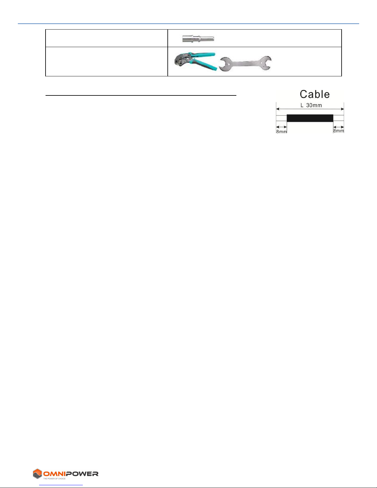
Male terminal
Crimping tool and spanner
Cable preparation and connector assembly process:
Strip one cable 8 mm on both ends and be careful NOT to nick or
bend any of the strands.
Insert stripped cable into female terminal and crimp female
terminal as shown below.
Insert assembled cable into female connector housing as shown below.
Insert stripped cable into male terminal and crimp male terminal as shown below.
Insert assembled cable into male connector housing as shown below.
6. PV Module (DC) Connection
11 www.sinetech.co.za
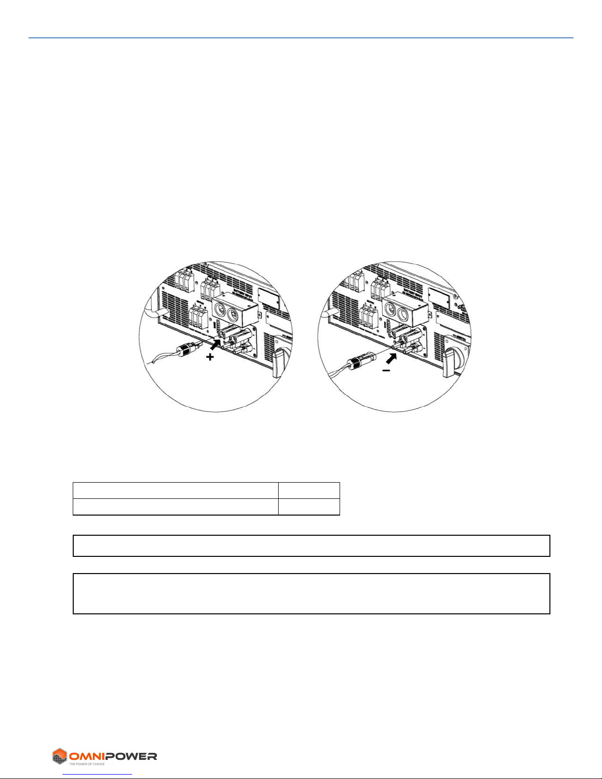
Use spanner to screw compression nut tightly to female and male connector as shown
below.
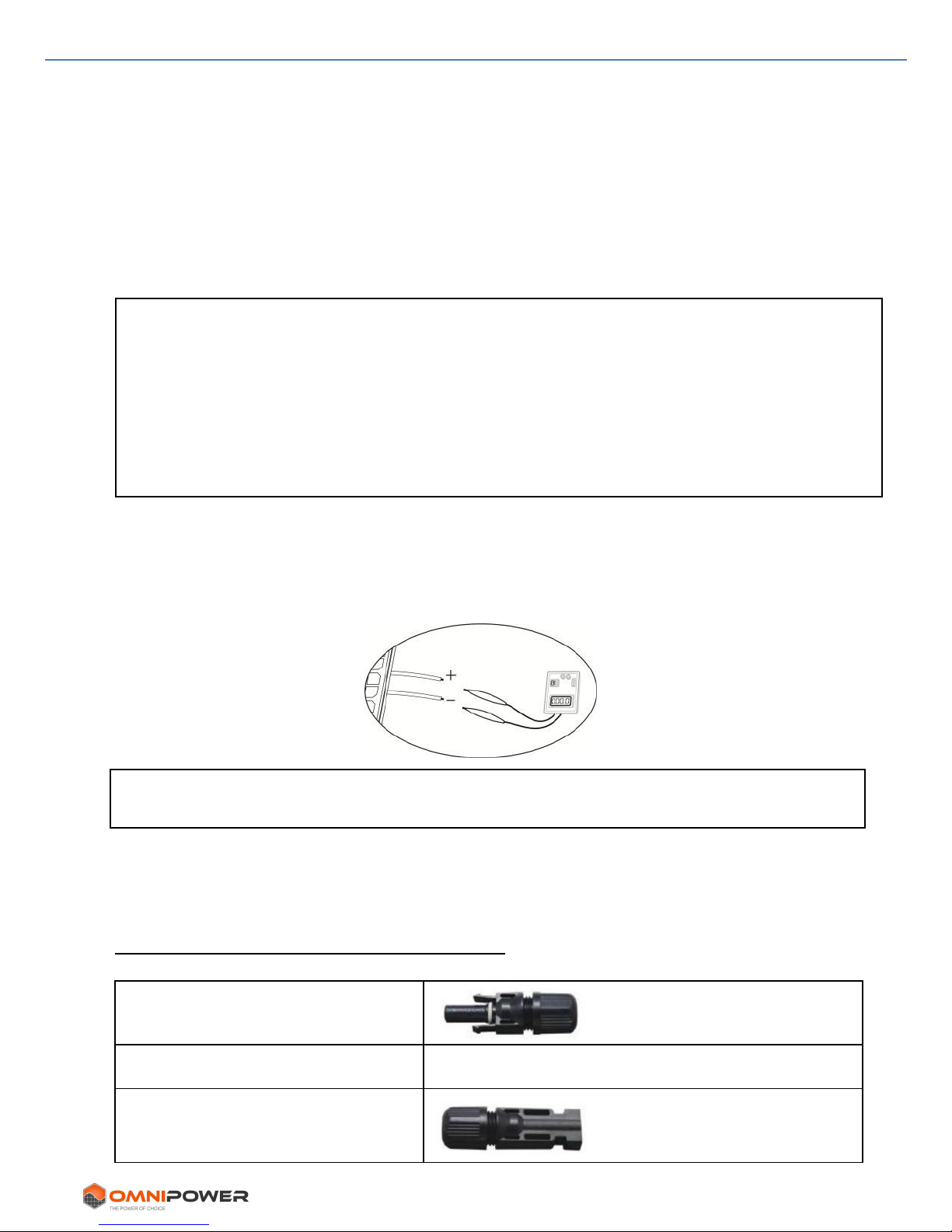
Step 4: Check correct polarity of cable from PV modules to PV input connectors.
Connect positive pole (+) of cable to positive pole (+) of PV input connector.
Connect negative pole (-) of cable to negative pole (-) of PV input connector.
WARNING! It is very important for system safety and efficient operation to use
appropriate UV resistant cable for PV module connection. To reduce risk of injury, use
the recommended cable size as below:
Conductor cross-section (mm2)
AWG no.
4
12
CAUTION: To avoid electric shock, DO NOT touch the inverter.
PV modules exposed to sunlight will generate high DC voltage which can be lethal
CAUTION: Never touch any inverter terminal. It will cause lethal electric shock.
6. PV Module (DC) Connection
12 www.sinetech.co.za
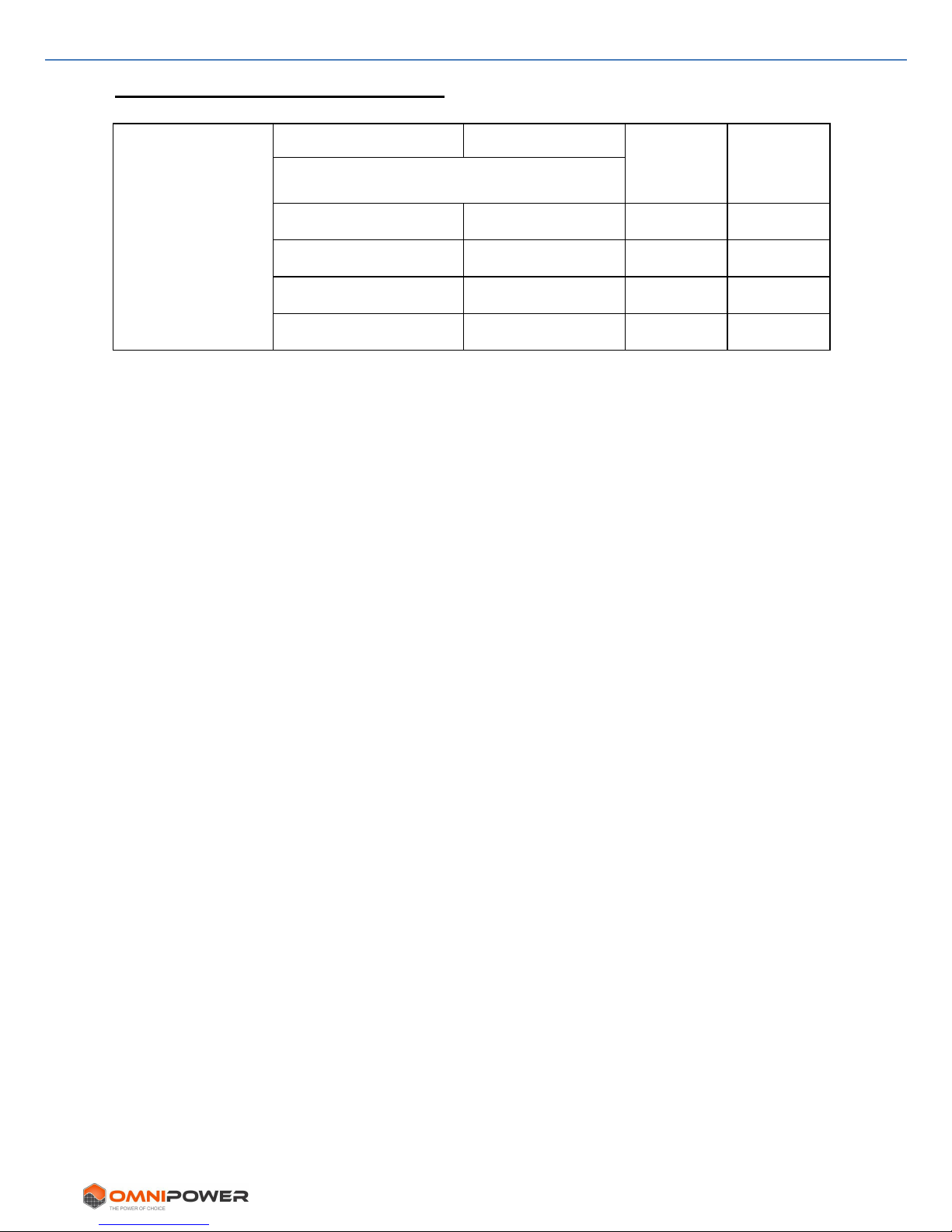
Recommended Panel Configuration
Solar Panel
Spec.
(reference)
- 250Wp
- Vmp: 36.7Vdc
- Imp: 6.818A
- Voc: 44Vdc
- Isc: 7.636A
- Cells: 72
SOLAR INPUT 1
SOLAR INPUT 2
Quantity
of panels
Total
Input
Power
(Min in serial: 11pcs;
Max. in serial: 18pcs)
11pcs in serial
x
11pcs
2750W
x
11pcs in serial
11pcs
2750W
11pcs in serial
11pcs in serial
22pcs
5500W
18pcs in serial
18pcs in serial
36pcs
9000W
7. Battery Connection
13 www.sinetech.co.za
7. Battery Connection
CAUTION: Before connecting batteries, please install an additional fuse / DC circuit
breaker between inverter and batteries.
NOTE1: Use only sealed lead acid, vented or Gel battery. Check maximum charging
voltage and current before using this inverter. For Lithium iron or NiCad battery, please
consult with installer for details.
NOTE2: Please use 60VDC/125 – 250A fuse / circuit breaker.
NOTE3: The overvoltage category of the battery input is II.
Please follow below steps to implement battery connection:
Step 1: Check the nominal voltage of batteries. The nominal inverter input voltage is
48VDC.
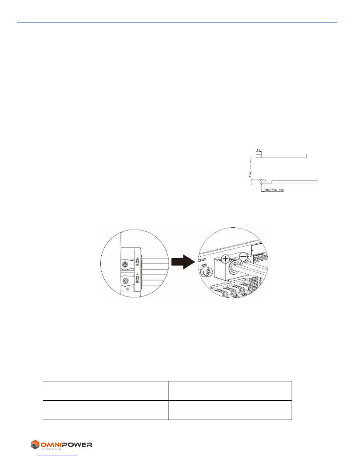
Step 2: Use two battery cables. Remove insulation sleeve 12
mm and insert conductor into cable ring terminal. Refer to
chart on right.
Step 3: Remove battery cover and follow battery polarity guide
printed near the battery terminal! Place the external battery cable ring terminal over the
battery terminal.
RED cable to positive terminal (+); BLACK cable to negative terminal (-).
WARNING! Incorrect connections will damage the unit permanently. NO warranty.
Step 4: Make sure the wires are securely connected. The tightening torque is 2.04 N.m.
WARNING! For system safety and efficient operation, use appropriate cables.
To reduce risk of injury, use recommended cable size as below.
Nominal Battery Voltage
48V
Conductor cross-section (mm2)
50
AWG no.
0
8. Load (AC Output) Connection
14 www.sinetech.co.za
8. Load (AC Output) Connection
CAUTION: To prevent continued supply to the load via the inverter during any mode of
operation, an additional disconnection device (circuit breaker) must be installed.
WARNING! It's very important for system safety and efficient operation to use
appropriate cable for AC connection. To reduce risk of injury, please use the proper
recommended cable size as below:
Model
5KW
Nominal Grid Voltage
230VAC
Conductor cross-section (mm2)
6
AWG no.
10
Step 1: Remove insulation sleeve 8 mm for three conductors. Shorten phase and neutral
conductors to 3 mm. Refer to chart 4.
Step 2: Connect wires according to polarities indicated on
terminal block. Be sure to connect PE protective
conductor ( ) first. Refer to Chart 5.
L→LINE (brown or black)
→Ground (yellow-green)
N→Neutral (blue)
Step 3: Make sure the wires are securely
connected. The tightening torque is 0.8 N.m.
CAUTION: Only connect load to “AC Output Connector”. NEVER connect the utility to “AC
Output Connector”.
CAUTION: Be sure to connect L terminal of load to L terminal of “AC Output Connector”
and N terminal of load to N terminal of “AC Output Connector”. The G terminal of “AC
Output Connector” is connected to ground of the load. Do NOT swop connections.
CAUTION: This inverter is not designed to operate in parallel. Do NOT parallel connect
multiple inverters as this will damage the inverter. Not covered by warranty!
L
N
Chart 4
Chart 5
8. Load (AC Output) Connection
15 www.sinetech.co.za
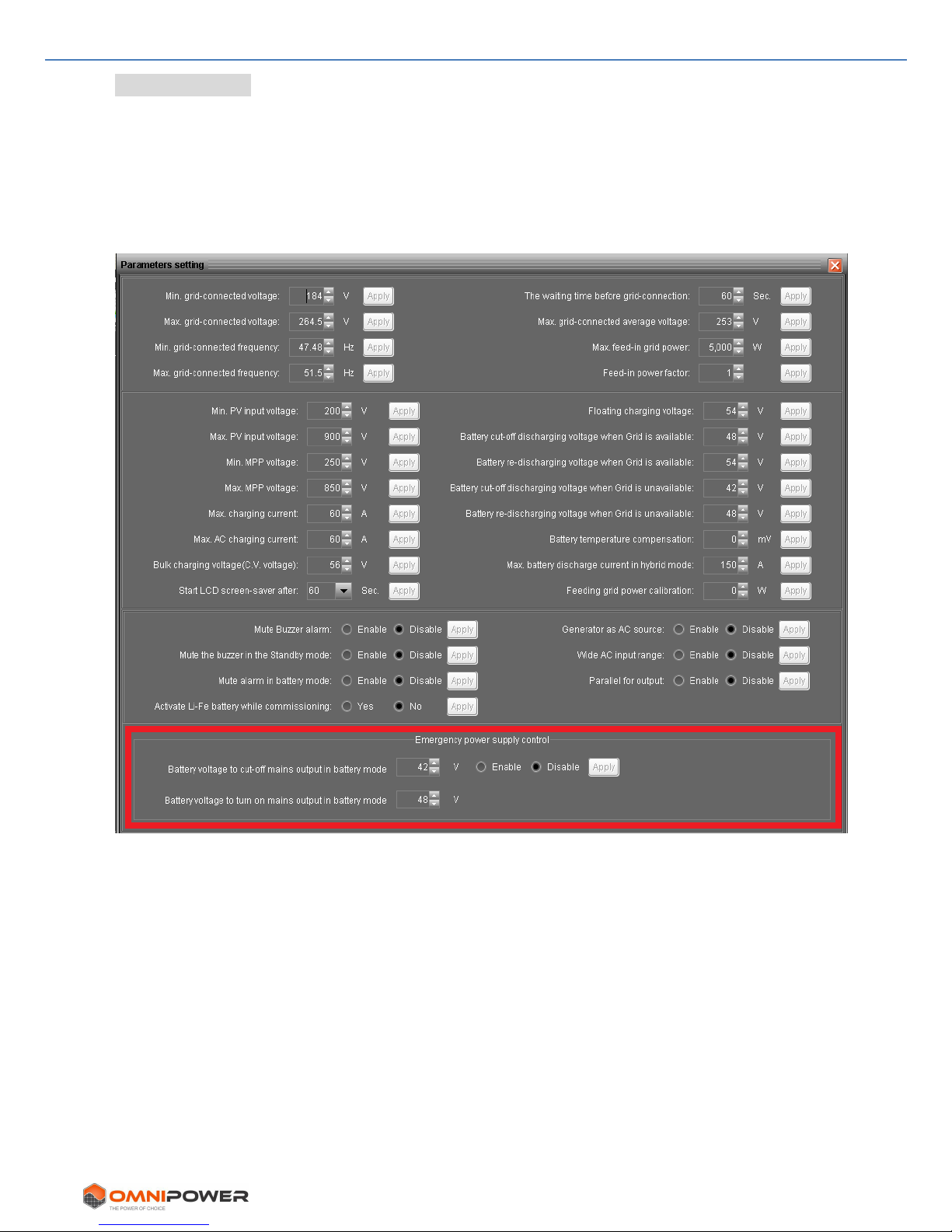
Software Setting
Please set up mains output in parameter setting of software. When “Emergency power
supply control” is enabled and inverter is working in battery mode, it will cut off AC
output but maintain limited power to the EMS port until battery voltage drops down to
the setting value in “Battery voltage to cut-off AC output in battery mode”. After that, if
battery voltage recovers to the setting value in “Battery voltage to turn on AC output in
battery mode”, inverter will turn on AC output again.
9. EMS Connection
16 www.sinetech.co.za
9. EMS Connection
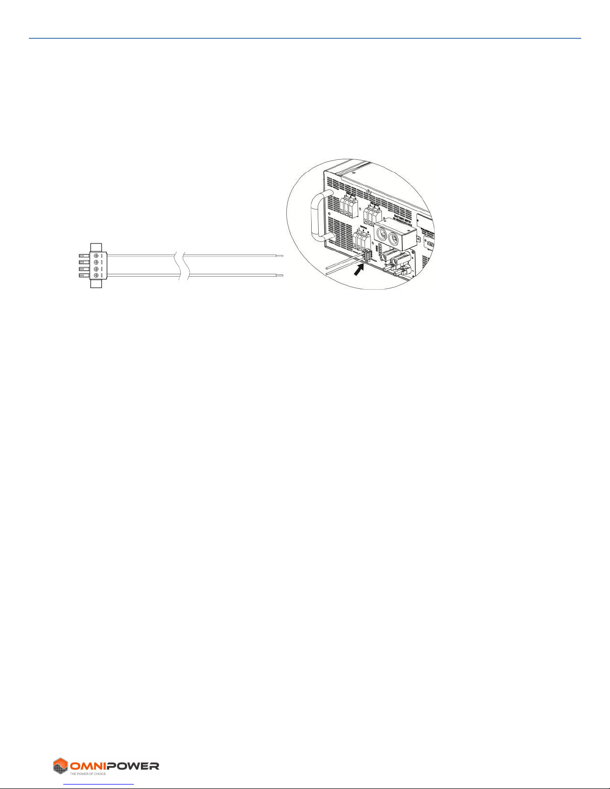
This port is available to provide limited power (230V/5A) for emergency lights, etc.
9-1 Interface Configuration
There are four pins on this port. However, only Pin 1 (Line) and Pin 4 (Neutral) are
useable. Use supplied cables to connect Pin 1 and Pin 4 shown as below.
9-2. Function Description
If “Emergency power supply control” is enabled, EMS port will be active. Even though
battery voltage drops to cut-off AC output point, EMS port will maintain output power for
emergency use.
 Loading...