

Page 1

Page 2
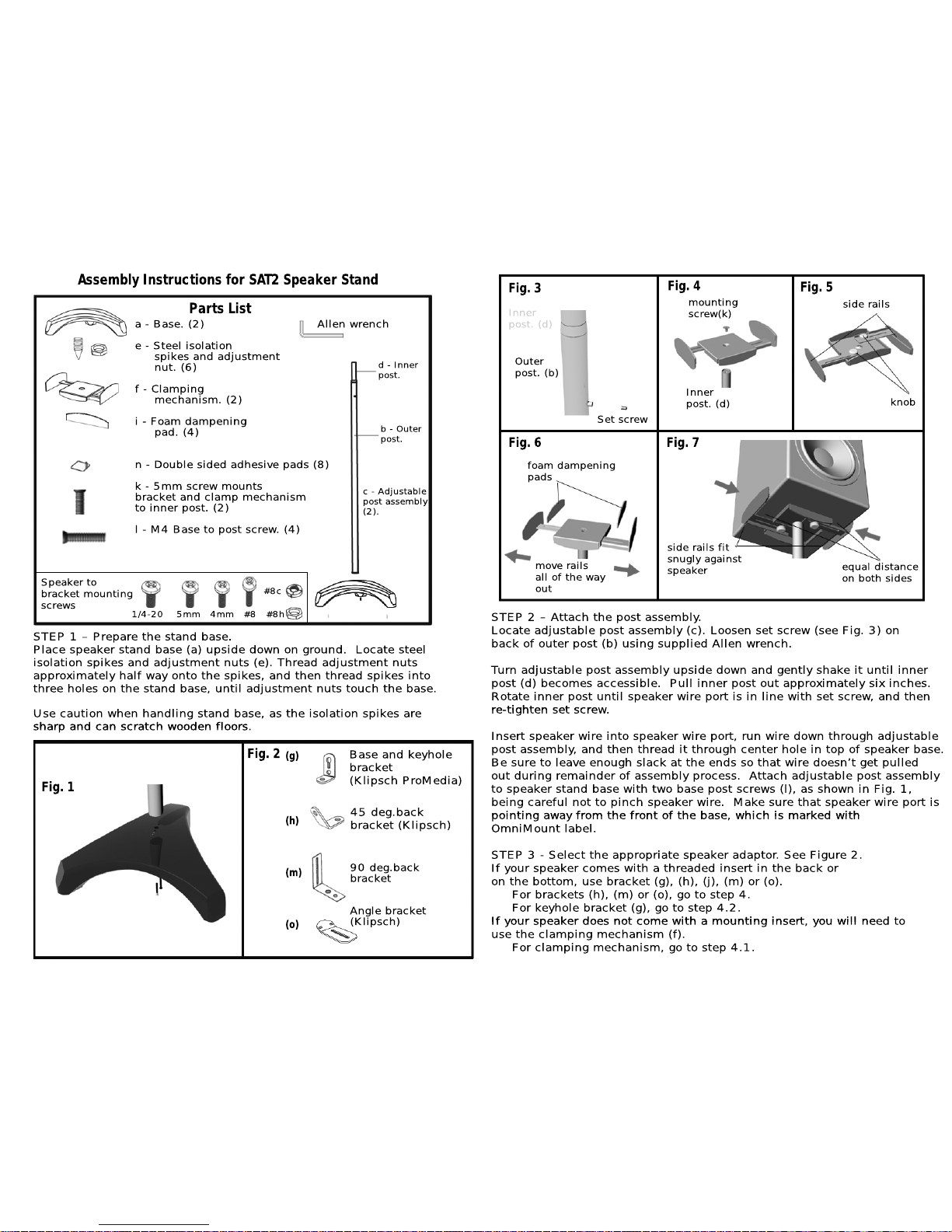
STEP 1 – Prepare the stand base.
Place speaker stand base (a) upside down on ground. Locate steel
isolation spikes and adj
ustment nuts (e). Thread adjustment nuts
approximately half way onto the spikes, and then thread spikes into
three hole
s on the stand base, until adjustment nuts touch the base.
Use caution when handling stand base, as the isolation spikes a
re
sharp and can scratch wooden floors.
sharp and can scratch wooden floors.
Assembly Instructions for SAT2SpeakerStand
b - Outer
post.
d - Inner
post.
Fig. 3
Parts List
a - Base. (2) Allen wrench
e - Steel isolation
spikes and adjustment
nut. (6)
f - Clamping
mechanism. (2)
i - Foam dampening
i - Foam dampening
pad. (4)
n - Double sided adhesive pads (8)
k - 5mm screw mounts
bracket and clamp mechanism
to inner post
. (2)
l - M4 Base to post screw. (4)
c - Adjustable
post assembly
(2).
Speaker to
bracket mounting
screws
#8c
1/4-20 5mm 4mm #8 #8h
(g)
(h)
(m)
(o)
Base and keyhole
bracket
(Klipsch ProMedia)
45 deg.back
bracket (Klipsch)
90 deg.back
bracket
Angle bracket
(Klipsch)
Fig. 1
STEP 2 – Attach the post assembly.
Locate adjustable post assembly (c). Loosen set screw (see Fig. 3) on
back of outer post (b) using supplied Allen wrench.
Turn adjustable post assembly upside down and gently shake it until inner
post (d) beco
mes accessible. Pull inner post out approximately six inches.
Rotate inner post until speaker wire port is in line with s
et screw, and then
re-tighten set scre
re-tighten set screw.
Insert speaker wire into speaker wire port, run wire down through adjustable
post assembly, and t
hen thread it through center hole in top of speaker base.
Be sure to leave enough slack at the ends so that wire doesn’t get p
ulled
out during remainder of assembly process. Attach adjustable post assembly
to speaker stand base with two base post screws (l), as shown in Fig. 1,
being careful not to pinch speaker wire. Make sure that speaker wire port is
pointing away
from the front of the base, which is marked withpointing away from the front of the base, which is marked with
OmniMount label.
STEP 3 - Select the appropriate speaker ad
aptor. See Figure 2.
If your speaker comes with a threaded insert in the back or
on the bottom, use bracket (g), (h), (j), (m) or (o).
For brackets (h), (m) or (o), go to step 4.
For keyhole bracket (g), go to step 4.2.
If your speaker does not come wit
h a mounting insert, you will need toIf your speaker does not come with a mounting insert, you will need to
use the clamping mechanism (f).
For clamping mechanism, go to step 4.1.
foam dampening
pads
move rails
all of the way
out
Fig. 4
Outer
post. (b)
Fig. 2
Set screw
Inner
post. (d)
side rails fit
snugly against
speaker
equal distance
on both sides
side rails
knob
Fig. 5
Fig. 6 Fig. 7
Inner
post. (d)
mounting
screw(k)
 Loading...