

Page 1
Step 10
Route your systems cables through Cable Ports and out through opening in rear
of Back Post.
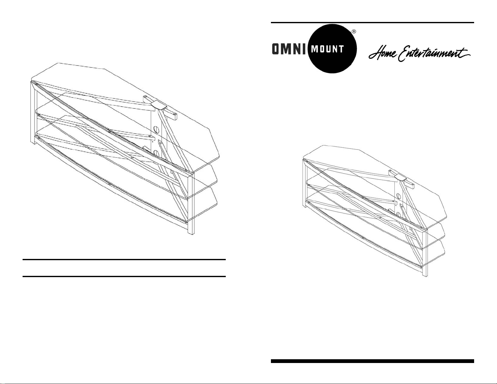
Assembly Instructions
Stellar Video Table: G363
Thank you for purchasing an OmniMount product.
Specifications are subject to change without prior notice.
Every effort has been made to provide accurate and error-fr ee assembly and installation. OmniMount
Systems disclaims liability for any difficulties arising from the interpretation of information contained
in these instructions. If OmniMount products are used for purposes other than their original intent,
OmniMount, its distributors and retailers shall not be held responsible or liable for injuries or property
damage, direct, indirect, or consequential, which may arise from the inability to use this product safely,
properly, and in the manner for which it has been designed and manufactured. Warranty does not
apply to products which have been lost, damaged by misuse, abuse, or accident.
8201 South 48th Street • Phoenix, AZ 85044-5355
8
OmniMount Systems, Inc.
www.omnimount.com
P/N 1002697 Rev A 02/2005
• Three shelf video table
• Adjustable center shelf
• Ideal for large LCD/DLP, Plasma TV’s
• Cable management
IMPORTANT: Consult your dealer if you have any questions regarding
the proper assembly of this product.
Page 2
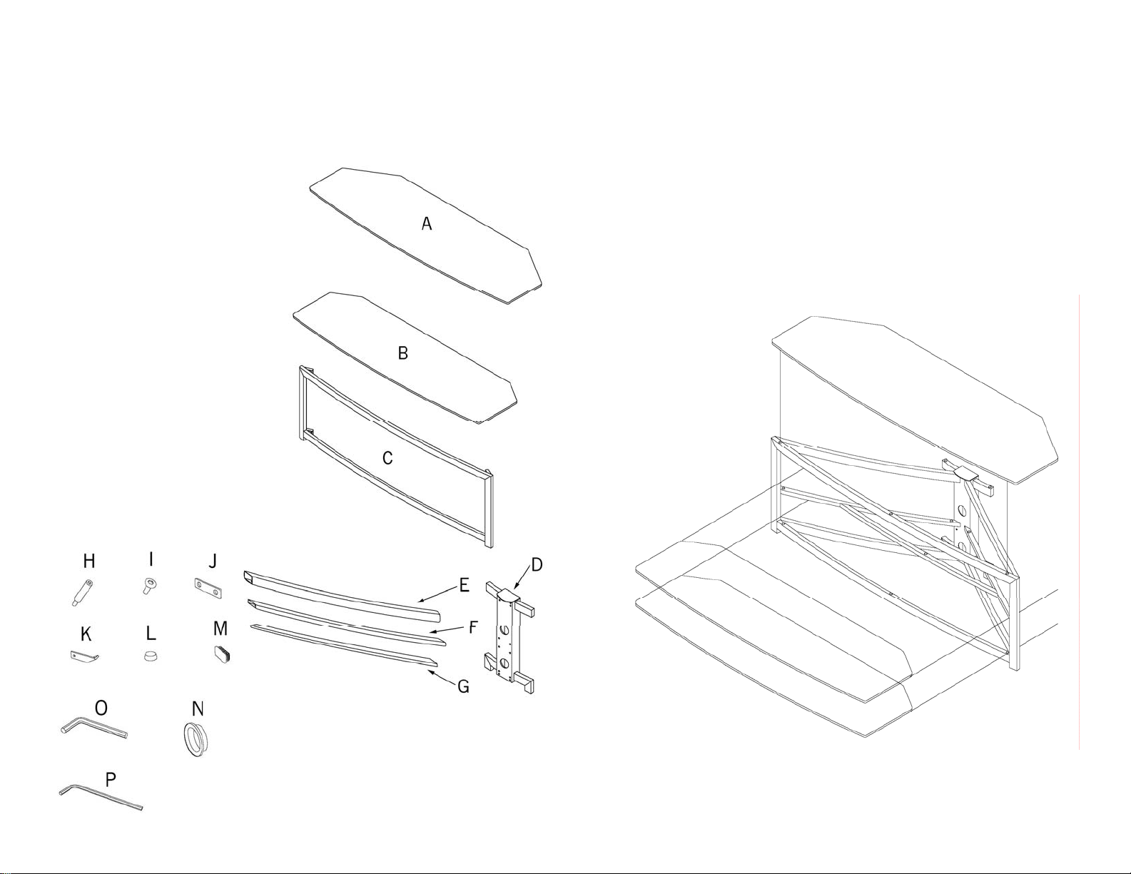
Components:
ID Description Qty.
Top Glass Shelf 1
A
Middle/Bottom Glass
B
Shelves
Main Frame 1
C
Back Post 1
D
Main Support Legs 4
E
Center Support Legs 2
F
Center Cross Bar 1
G
Long Hex Head Screws 10
H
Hex Screws 18
I
Cross Bar Bracket 2
J
Center Support Bracket 2
K
Self Adhesive Pads 16
L
End Caps 4
M
Cable Port Covers 2
N
2
Step 9
Refer to Fig. 9.
Carefully lift and slide Bottom Glass Shelf (B) into place on lower frame members.
Carefully lift and slide Middle Glass Shelf (B) into place on center frame members.
Lift Top Glass Shelf (A) into place on top frame members.
Note: If the top shelf glass is unstable, move the rubber pad positions or, using the
extra adhesive pad, double up the height of the lowest pad until the shelf glass is
stable.
Caution: Never try to move table by pulling on glass shelves. Always move table by
grasping the table frame assembly.
Fig. 9
Large Hex Wrench 1
O
Small Hex Wrench 1
P
2
7
Page 3

Step 7
Rock table to check that it is level and stable. For unstable condition, unscrew
shortest Leveling Foot until table sits level.
Peel Self Adhesive Pads (L) from backing paper, and apply to table assembly as
indicated by the black dots, as shown in Fig. 7.
Note: There should be 5 Adhesive pads applied to each shelf.
Fig. 7
Step 1
Refer to Fig. 1.
Install End Caps (M) into bottom of Main Frame (C) using rubber mallet.
Determine desired location of middle shelf; high or low. Install Center Support
Brackets (K) to desired
shelf location with Hex
Screws (I), and Small Hex
Fig. 1
Wrench (P).
Step 2
Insert open end of Main Support Legs (E) and Center Support Legs (F) over brackets on Main Frame, as shown in Fig. 2.
6
Fig. 8
Step 8
Identify Glass Shelves by shape, as
shown in Fig. 8.
Note: The curve on the Support Legs should face inwards, and the mounting
holes should face towards the bottom of the Main Frame.
Fig. 2
3
Loosely secure Support
Legs to Main Frame with
Hex Screws.
Page 4
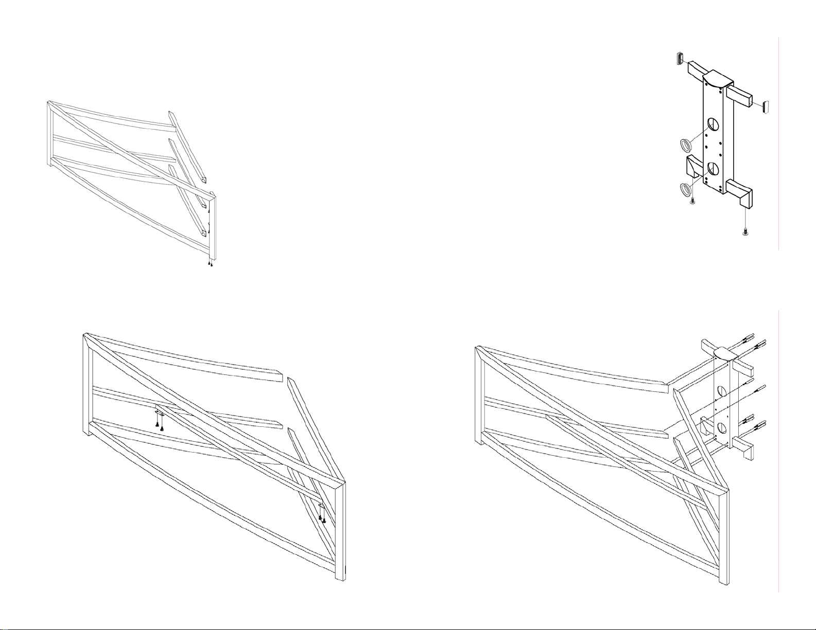
Step 3
Install Main and Center Support Legs over brackets on the other side of Main
Frame, as shown in Fig. 3. Loosely secure Support Legs to Main Frame with Hex
Screws.
Fig. 3
Step 4
Attach Center Cross Bar (G) to Center Support Legs with Cross Bar Bracket (J) and Hex
Screws, as shown in Fig. 4.
Step 5
Fig. 5
Refer to Fig. 5.
Thread Hex Screws into bottom foot area of Back Post
(D). These will become the Leveling Feet for the completed table assembly.
Snap Cable Port Covers (N) into cable openings
on Back Post.
Install End Caps (M) into top section of Back Post
using rubber mallet.
Step 6
Install Back Post onto rear of Support Legs using Long Hex Head Screws (H)
and Large Hex Wrench (O), as shown in Fig. 6.
Tighten all Hex Screws on table assembly securely.
4
Fig. 4
Fig. 6
5
 Loading...