

Page 1
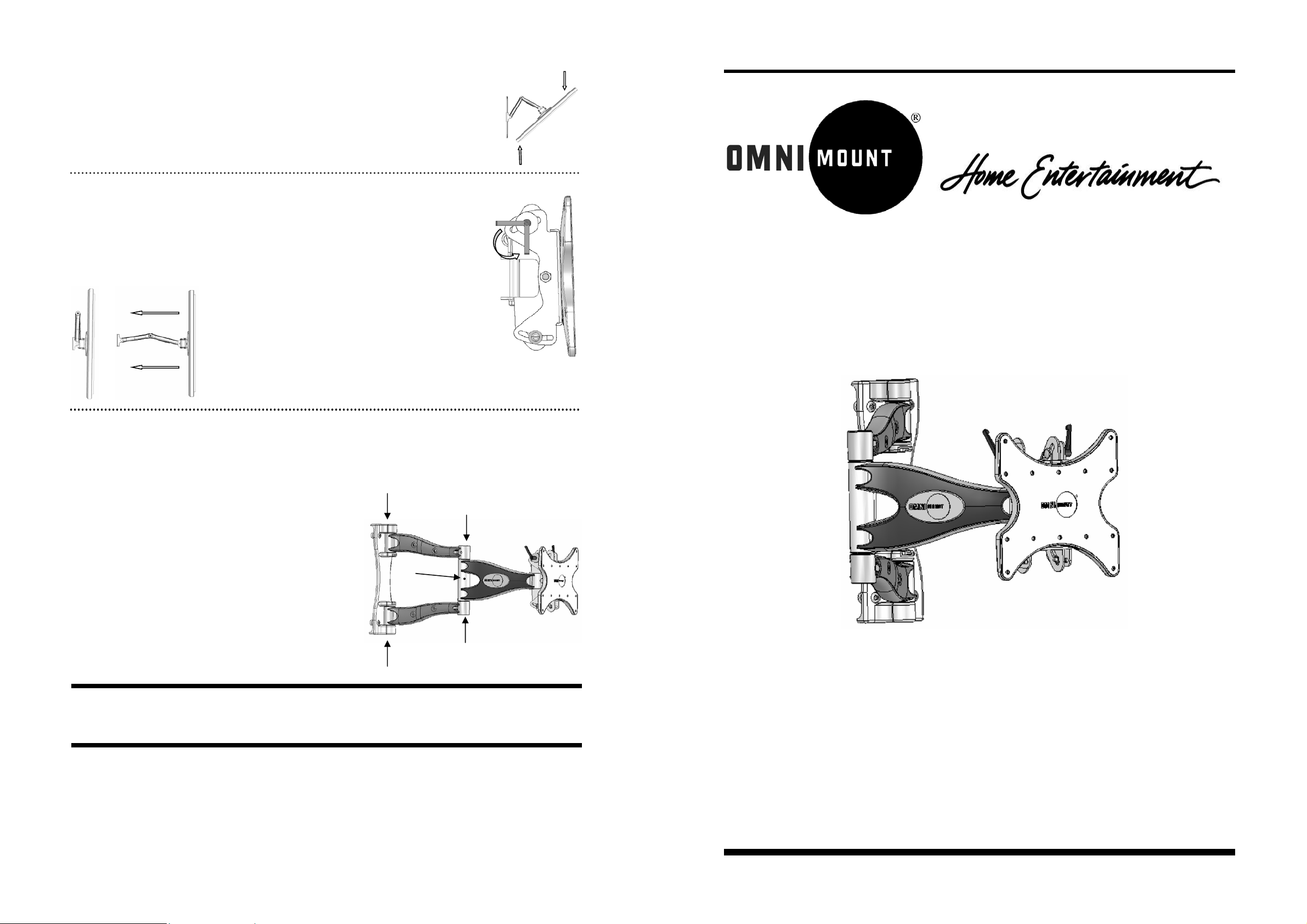
Panning—Position display at an angle to the wall for viewing from opposite sides of t he room.
Grasp the side edges of the display and then swivel and pull the display into desired position. (Fig 21)
Fig. 21
Before stowing the display, ensure the Tilt Lever s will not make contact with any surface when
closed. For example, if the Levers are pointed up, they could hit and damage the cable covers or
possibly release the tension.
Use the ratchet function to adjust the Lever position without changing the tension.
See Fig. 22 for acceptable positioning range.
Fig. 23
Fig. 24
CAUTION: WHEN REMOVING THE DISPLAY MAKE SURE THE HEAD IS LOCKED IN THE
NEGATIVE TILT POSITION, OTHERWISE INJURY COULD OCCUR.
Maintaining the CL-M
The arm assembly and wall plate may be cle aned with a mild solution of soap and water.
Stowing the Display—Positions the display ag ainst the wall.
Grasp the side edges of the display, swivel and pull the display into
the center position (Fig. 23), and then push the display straight back
towards the wall into the stowed position. (Fig.24)
Note: Use care when stowing the display to ensure that
cables do not become pinched.
Acceptable
Position
Range
Fig. 22
Installation Instructions
Wishbone Series™
CL-M: Medium Cantilever Mount
Caution: Be careful not to get water on the electrical connections or
the display.
If the Arm Assembly becomes loose and won’t maintain it’s position,
you can tighten the Arms at several points. Use the Medium supplied
Hex Wrench as indicated in Fig. 25.
Note: The elbow joint is pretensioned at the fac t ory and must be
adjusted by the Set Screw (25.1). To lock the arm in position, fully
tighten the Set Screw with the smallest (3mm) supplied Hex Wrench.
25.1
Fig. 25
Thank you for purchasing an OmniMount product.
Specifications are subject to change without prior notice.
Every effort has been made to provide accurate and error-free assembly and installation. OmniMount Systems disclaims liability for any difficulties arising from the interpretation of information contained in these instructions. If OmniMount products are used for purposes other than
their original intent, OmniMount, its distributors and retailers shall not be held responsible or liable for injuries or property damage, direct,
indirect, or consequential, which may arise from the inability to use this product safely, properly, and in the manner for which it has been designed and manufactured. Warranty does not apply to products which have been lost, damaged by misuse, abuse, or accident.
• Designed for 23” - 37” Flat Panel TV’s
• Maximum Weight Capacity: 80 lbs. (36.3 Kg)
• VESA compliant: VESA 100, 100 x 200, 200 x 200
• Installation Template Included
• Integrated Cable management
• Lift N’ Lock Installation
• Non-VESA Panels may require optional adaptor plate
Questions? Call 1-800-MOUNT-IT (USA only)
8
CL-M: PN 1002785-RevB-8/05
Page 2
IMPORTANT
•
Do not begin the installation of your OmniM ount product until you have thoroughly reviewed this d oc ument and
understand the instructions.
• We highly recommend that this product be installed by a qualified professional.
• Make sure that the wall you plan to use will safely support four times the combined weight of the mounted equip-
ment, including its accessories.
• Under no circumstances should this product be mounted to metal framing studs.
• NEVER exceed the Maximum load capacity of 80 lbs. (36.3 Kg)
Table of Contents
Installation Tools
Parts List
Components
Determine the Mounting Location
The Installation Template
Mounting to the Wall
Attaching the Display
Using Cable Management
Adjusting the Display
Maintaining the Mount
Installation Tools:
Electronic Stud Locater (Wooden stud installation only)
Variable Speed Electric Drill
Hammer Drill (Concrete installations only)
Drill Bits:
3/16” (5 mm) drill bit (Wooden stud installation only)
1/2” (13 mm) masonry drill bit (Concrete installations on ly)
Hammer (Concrete/Masonry installation only)
Ratchet Wrench with 9/16” socket
Phillips head screwdriver
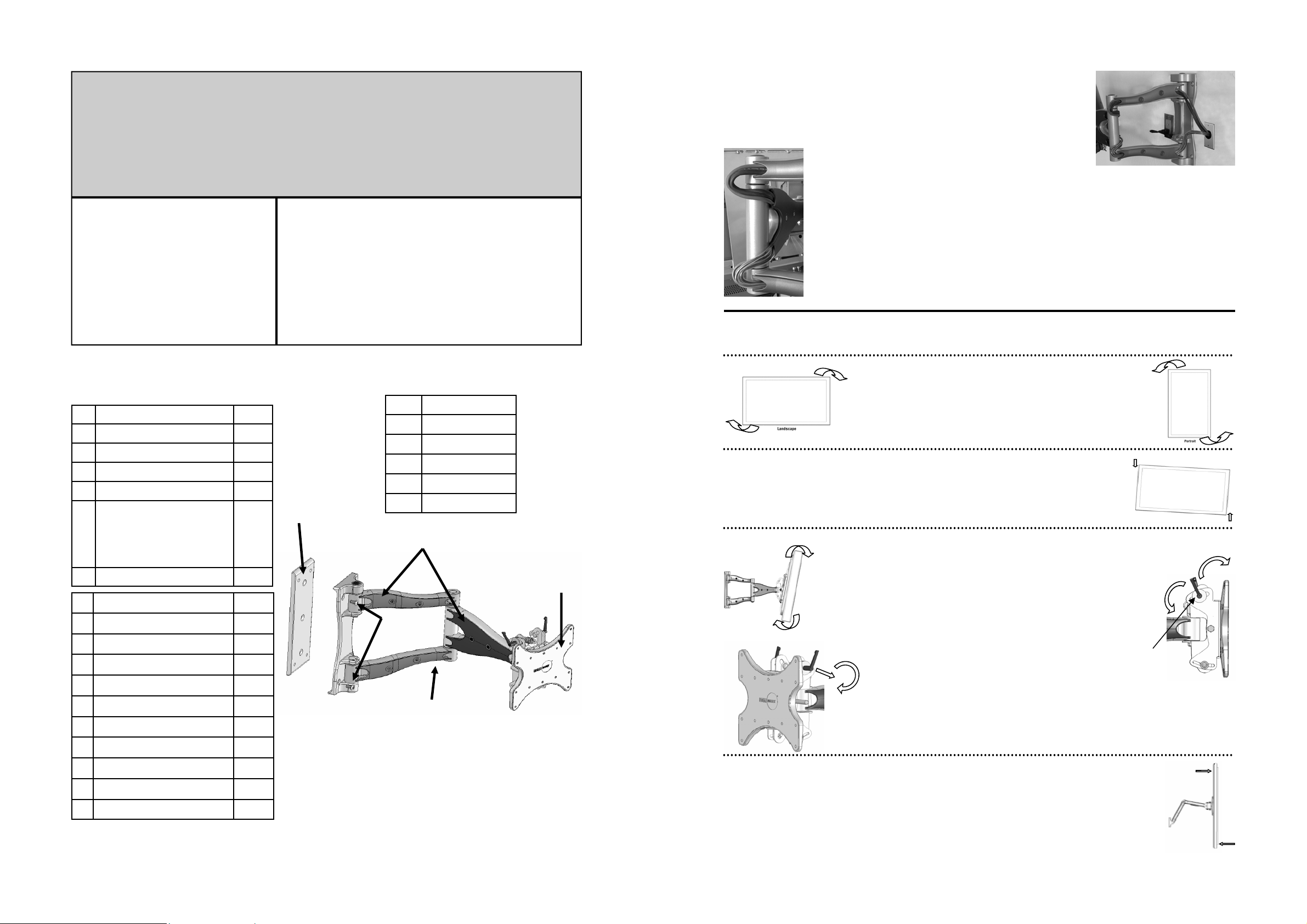
Route the cables along one side of the Inner Arm (nearest the wall plate), as shown in
Fig. 13. With cables in place, loosely secure the Inner Arm cable covers back in place.
Fig. 13
Fig. 14
Next, route the cables along the opposite side of the Outer Arm, as shown in Fig. 14. Be sure to
leave slack in the cable where it transitions between t he two sides of the Arm Assembly. With cables in position, loosely secure the Outer Arm cable covers bac k in place.
Note: For best system performance, route the AC power cable separately fro m the signal cables.
With all cables in place, pull the display in and out and check that the arm assembly moves freely,
without stretching or damaging the cables, and then secure the cable covers.
Important: DO NOT use a hex wrench on the Retaining Nuts (11.2), only apply pressure with your finger.
Step 7 — Adjusting the Display
The Wishbone series cantilevers provide a wealth of display adjustment to offer the best viewing from a number of seating positions.
Parts List:
ID Description Qty.
1 Lag Bolts: 5/16” x 2” 3
2 Wall Anchors 3
3 Mounting Temp late 1
4 Thumb Tack 1
Hex Wrenches: 3
Extra Small 3mm
5
Small Diameter 4mm
Medium Diameter 5mm
Large Diameter 6mm
6 1/4" Spacers 12
ID Description Qty.
A Philips screws M4 x 12mm 6
B Philips screws M5 x 12mm 4
C Philips screws M6 x 12mm 4
D Philips screws M4 x 25mm 6
a)
Components:
ID Description
a) Wall Plate
b) Shoulder Screws
c) Cable Covers
d) Mounting Head
e) Arm Assembly
c)
b)
d)
Portrait/Landscape View—Position the display for vertical or
Fig. 15
horizontal viewing.
Grasp the edge of the display and turn it to the desired position.
(Fig 15 & 16)
Roll Control—Horizontal leveling of the display.
Grasp the edge of the display and roll it up or down into a level position. (Fig 17)
Tilt—Raising or lowering the screen to improve viewing angle/
Fig. 18
picture quality.
Adjust Tilt Lever (19.1) until the display will not move forward with-
out manual adjustment, yet can still be moved with minimal effort.
(Fig. 19)
Grasp the upper and lower edges of the disp lay, and then push or
pull the display to the desired tilt angle. (Fig 18)
To lock the tilt angle, tighten the Tilt Levers (19.1) securely. (Fig. 19)
For heavier displays, never fully release the Tilt Lever wit hout
fully supporting the display
.
Fig. 19
Loosen
19.1
Fig. 16
Fig. 17
Tighten
E Philips screws M5 x 25mm 4
F Philips screws M6 x 25mm 4
G Philips screws M4 x 40mm 6
H Philips screws M5 x 40mm 4
I Philips screws M6 x 40mm 4
J Philips screws 1/4”-20 x 5/8” 4
2
e)
The Tilt Lever includes a ratchet function, so that it can be lifted and repositioned for the next
turn. To operate the ratchet, pull the lever straig ht out, rotate it to an unobstructed position, release the lever, and then turn it in the desired direction. Repeat as necessary until the tilt tension
is set properly. (Fig. 19)
Fig. 20
Swivel—Adjust the display for off center viewing positions.
Grasp the side edges of the display and then swivel display into desired position. (Fig 20)
7
Page 3

Some displays will require the use of a spacer between the mounting head and the
back of the display because the display has a recessed mounting area or a curved back.
In this case, use the long screws in pouches G, H or I, along with one or two spacers, as
required, (7) for each screw.
Secure Mounting Head to back of display using the selected mounting screws (9.1) and
spacers (9.2) if required. (Fig 9)
9.1
9.2
Step 1 — Determine the Mounting Location
To provide maximum viewing flexibility, the OmniMount Wishbone Series cantilever mounts are capable of a wide ra nge
of motion, which allows the display to be positioned f or vi ewing from many different angles.
When selecting the mounting location for the display, make sure there is adequate space on all sides of the display, considering the dimensions (H x W) of your particular display model.
Caution: NEVER force screws into the display, as damage may occur. NEVER use
an electric drill to secure the screws.
Fig. 9
Negative Tilt
CAUTION: WHEN REMOVING THE DISPLAY MAKE SURE THE HEAD IS LOCKED
IN THE NEGATIVE TILT POSITION, OTHERWISE INJURY COULD OCCUR.
Fig. 10
Carefully lower the display into position on the Mounting Arm. Make sure to align
the slots on the Mounting Head with flanges on the end of the Mounting Arm.
While holding the display in position, gently pu ll the bottom of the display forward
to create enough space to insert the Clamp Plate ( 10.1) and Tens ion Screws (10.2).
(Fig 10)
Insert and tighten enough to prevent the screen from moving easily.
10.2
Using an Adaptor Plate
If your display is not VESA compliant, you will need to use an adaptor plate b etween your display and the CL—M. Attach
the adaptor plate and mount the display as per the adaptor plate instructions.
10.1
Step 2 — The Installation Template
The Installation Template is designed to make the installation of the CL-M faster, easier and more accurate. The template
also includes a built in dust channel to reduce the clean up chores from mounting the CL-M.
Assembling the Dust Channel:
Locate the supplied mounting template. (Fig. 1)
Fold the dust collector along the marked lines:
a. Fold main channel up.
b. Crease and fold the tab sections inward.
c. Fold outer portion of tab around the back of the guide,
d. and then insert tab into slot.
Fig. 1
Step 3 — Mounting to the Wall
Follow the instructions based upon your mounting surface:
3a Wooden Stud
3b Concrete/Masonry
3c Cinder Block
If an adapter plate is required, OmniMount recommends the UA-M or model specific Adapter Plate for the CL-M
Step 6 — Using Cable Management
The Wishbone series cantilevers include a cable management function, where cables can be routed along the length of the
arm assembly.
To install cables, you’ll first need to remove the cable covers. Using a Phillips Head sc rewdriver on the Retaining Screw
(11.1) and pushing on the Retaining Nuts (11.2) with your finger, remove the screw assembly (Fig. 12). Remove the Cable
Covers (11.3) and set all parts aside.
Fig. 11
Fig. 12: Screw Assembly
11.2
Retaining Screw
11.1
11.3
6
Cover Washer Plastic Sleeve
Step 3a — Mounting to Wooden Studs
The CL-M wall plate can be mounted on a single wooden stud.
Using an electronic stud finder (Fig 2), locate the center of th e wooden stud at the desired mounting locati on.
Mark the stud center position directly onto the wall. Extend the stud center line, and then draw a horizontal
line where you wish the center of the screen to be located. Measure and mark the center position of this horizontal line.
Insert supplied thumbtack into center mark on template. Rem ov e th e tape strip from the back of the guide. Remove the
four square perforations above center hole to help alig n the template with the center mark of the stud. Pin the template to
the center mark. Using a bubble level, level the guide, and then press the adhesive backing against the wall to hold the
guide in place.
Note: Depending upon the roughness of the surface, you may need to hold the template in place with an additional application of tape or blue painter’s tape.
Using a 3/16” (5 mm) drill bit, drill 3 pilot holes 3.0” (76 mm) deep into the center of the studs, through the circular cutout sections of the installation template.
Note: For best results from the dust channel, press and hold the temp late against the wall about 2” (50 mm) from where
you are drilling.
Carefully remove the guide from the wall, and discard. Note: Be sure to hold the guide in an upright position so as not to
spill the collected dust.
Fig. 2
3
Page 4

Step 3b — Mounting to Concrete/Masonry
The CL-M wall plate can be mounted directly to concrete/masonry walls.
WARNING
•
NEVER drill into mortar joints!
• Concrete must be 2000 PSI density minimum.
Fig. 3
Remove the tape strip from the back of the template, and place the template in the desired location. Using a bubble level,
hold the template in a level position an d then press the adhesive backing against the w all to hold the guide in place.
Note: Depending upon the roughness of the surface, you may need t o hold the template in place with an additional application of tape or blue painter’s tape.
Using a 1/2” (13 mm) masonry drill bit, drill 3 mounting holes 3.5” (89 mm) deep into the concrete/masonry surface. Drill
through the mounting hole cut-out sections of the template.
Note: For best results from the dust channel, press and hold the template against the wall about 2” (50 mm) from where
you are drilling.
Carefully remove the guide from the wall, and dis card. Note: Be sure to hold the guide in an upright position so as not to
spill the collected dust.
Insert wall anchors into the mounting holes, and lightly tap them flush to the wall with a hammer. (Fig. 3)
IMPORTANT
Masonry anchors MUST be seated firmly against the concrete or masonry. If mounting to a masonry wall covered with drywall/
plaster, counter bore a hole through the drywall/plaster around the mounting hole location, so that the anchor can be seated
directly against the concrete or masonry.
Step 4 — Mounting to the Wall
Remove the cantilever assembly from the b ox.
Using the Large supplied hex wrench, remove the Shoulder Screws (4.1) from the
Shoulder Assembly (4.2). Separate the Shoulder Assembly from the Wall Plate
(located behind the Assembly). (Fig. 4)
Fig. 5
5.1
Carefully hold the Wall Plate (5.1) in position over the drilled mounting holes, and then securely bolt the wall plate to the wall with the supplied 5/16” lag bolts (2). See Fig 5.
4.2
IMPORTANT
Tighten lag bolts so that wall plate is firmly attached to wall, but DO NOT over tighten. The Lag bolts can
be damaged by over tightening, which greatly reduces their holding power. Final tightening of lag should
always be done by hand, with a ratchet wrench and socket.
Fig. 6
Fig. 4
4.1
Step 3c — Mounting to Cinder Block
The CL-M wall plate can mounted directly to cinder block walls.
WARNING
•
Cinder Block must meet ASTM C-90 specifications.
• Mount to solid portion of block, generally 1” from the sides.
• NEVER drill into mortar joints!
• Use standard drill set on slow speed/ high torque setting. DO NOT use hammer drill on cinder block.
• Verify that you have a minimum of 1 3/8” of actual concrete thickness in the mounting hole, before inserting the wall anchor.
Remove the tape strip from the back of the template. Using a bubble level, hold the template in a level position and then
press the adhesive backing against the wall to hold the guide in place.
Note: Depending upon the roughness of the surface, you may need t o hold the template in place with an additional application of tape or blue painter’s tape.
Using a 1/2” (13 mm) drill bit, drill 3 mounting holes 3.5” (89 mm) deep int o the cinder block surface. Drill through the
mounting hole cut-out sections of the template.
Note: For best results from the dust channel, press and hold the template against the wall about 2” (50 mm) from where
you are drilling.
Carefully remove the guide from the wall, and dis card. Note: Be sure to hold the guide in an upright position so as not to
spill the collected dust.
Insert wall anchors into the mounting holes, and lightly tap them flush to the wall with a hammer. (Fig 3)
IMPORTANT
Masonry anchors MUST be seated firmly against the concrete or masonry. If mounting to a wall covered with drywall/plaster, counter bore a
hole through the drywall/plaster around the mounting hole location, so that the anchor can be seated directly against the concrete or masonry.
With the Wall Plate (6.1) securely mounted to t he wall, place the Shoul-
6.1
der Assembly (6.2) over it and align the Shoulder Screw Holes on the
Assembly with the Corresponding Holes on the Wall Plate. Insert
Shoulder Screws (6.3) and tighten by hand. (Fig. 6)
6.2
Step 5 — Attaching the Display
Fig. 7
It’s easy to mount a flat panel display to the CL-M using the Lift N’ Lock mounting system. First, remove the Mounting Head (7.1) from the end of the arm assembly. To do this,
use the Small supplied hex wrench to remove the Tension Screws (7.2) from Clamp Plate
(7.3), and then slide the Clamp Plate out of the Mounting Head. Set these parts aside for
later. Next lift the Mounting Head straight up off the end of the arm assembly. See Fig. 7.
The Mounting Head of the CL-M is VESA
compliant, and supports the following VESA
Patterns (Fig. 8):
Fig. 8
Note: If your display is not VESA compliant, proceed to the section entitled Using an Adaptor Plate.
1: VESA 100 (100mm x 100mm)
2: VESA 200 (100mm x 200mm)
3: VESA 200 (200mm x 200mm)
The Mounting Head can be attached directly to VESA compliant flat panel displays, using the
appropriate Hardware. Consult the supplied Hardware Cross Reference list, and locate the
required mounting screws (A-I) for your display.
6.3
7.1
7.2
7.3
4
5
 Loading...