

Page 1
03
Car & Home Security System /
Please make sure of usage after bearing the following
contents in mind to shorten the safety, and product
failure before its operation.
1. Do not shock in move, and installation.
2. Please check rating voltage (mini type : DC12V 3.0A / mobile type : DC12V)
before power on.
3. Please check power off before installation.
4. Avoid any place with moisture because of electric shock, and fire.
5. Avoid any place with moisture, dust, or soot.
6. Avoid any place with direct sunlight, or heating appliances.
7. Avoid high, or low temperature.
8. Procure sufficient air ventilation for the connection of system wiring.
9. Don't install near to electronic devices such as radio, or TV.
10. Install in sufficient air ventilation, and no vibration.
11. Please take care of not putting the electric product into the cooling fan.
12. Don't use water, or cleanser in surface cleaning to prevent an electric shock.
13. Please clean system by dry towel in external cleaning.
14. Do not pull power cord forcefully.
15. Do not place any heavy object on the main system.
16.
Do not open, or disassemble DVR without an assistance of qualified service personnel.
17. Please power off in case of moving DVR.
18. Please equip with the safety facility to diminish the loss for electricity failure,
and lightning.
19.
Do not connect signal cable of camera with DVR system during camera installation.
20. Please power off immediately, and contact manufacturer, or supplier if you
catch strange scent, or smog.
NOTICE FOR SAFETY
Page 2
/ Car & Home Security System
04
NOTICE FOR SAFETY
- This equipment had been tested and found to comply with the limits for
CLASS A digital deice, pursuant to Part 15 of FCC Rules.
- These limits are designed to provide reasonable protection against
harmful interface when the equipment is operated in a commercial
environment.
1. Quick Setup Guide
2. Specification
3. Operation
4. Backup Viewer
5. Menu Setup
6. Troubleshooting
7. Warranty
FCC Compliance Statement Caution :
Any change, or modification in construction of this device which are
not expressly approved the party responsible for compliance could
avoid the user s authority to operate the equipment .
NOTE :
This equipment has been tested, and found to comply with the limits
for a Class A digital device, pursuant to part 15 of the FCC rules. This
limits are designed to provide reasonable protection against harmful
interference when the equipment is operated in a commercial
environment. This equipment generates, uses, can radiate radio
frequency energy, and , if not installed, and used in accordance with
the instruction manual, may cause harmful interference to radio
communications. Operation of this equipment in a residential area is
likely to cause harmful interference in which cause the user will be
required to convert the interference at his own expense.
Contents
Page 3
Quick Setup Guide
Car & Home Security System
Quick Setup Guide
STEP 1 Package Details
STEP 2 HDD Installation
STEP 3 Camera & Monitor Connection
STEP 4 Menu Setup
STEP 5 Operation Check
1. Monitor Check
2. LED Check
STEP 6 Backup Viewer
1. Date & Time Setup
2. Record Setup
Page 4
/ Car & Home Security System
08 09
Car & Home Security System /
Quick Setup Guide Quick Setup Guide
A Type (MINI)
STEP1.1 Package Details
DVR
Remote controller
Power cord
Battery
CD
A/V out cable
Adaptor
Manual
B Type (Mobile)
DVR
Remote controller
Screw
Screw
Battery
CD
A/V out cable
Bracket
Manual
Cigar jack
STEP 1.2 Optional Accessories
2. Camera input cable
1. Camera extention cable
1) Type A (MINI) : 60 feet cable
2) Type B (Mobile) : 20 feet cable
- DVR can support camera power up to max. 250 mA. If camera power is
over 250 mA, its own adaptor must be required.
-
Otherwise, DVR may be damaged and work abnormally.
For installation, please contact technial service personnel.
- Input : DC12V - DC35V - Output : DC 12V - Advanced power management
3. DC to DC converter (for car)
- Wired reomte control - LED indicator
4. External wired controller
Page 5
/ Car & Home Security System
10 11
Car & Home Security System /
Quick Setup Guide Quick Setup Guide
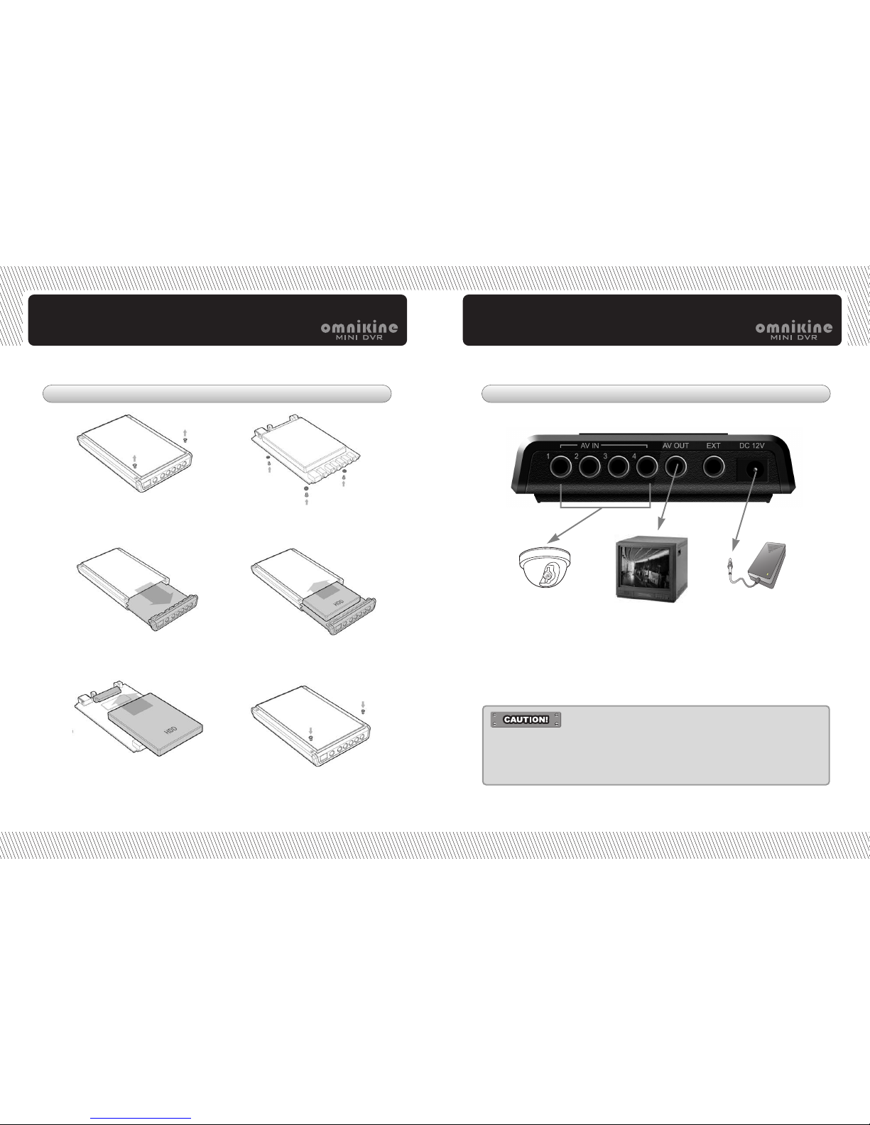
STEP2 HDD Installation
1. Unscrew 4 fixed screws on
the bottom of case.
2. Disassemble rear panel and
take out main board.
3. Fix HDD to SATA connector on
main board.
4. Insert rubber rings into screws
and then screw them to fix HDD
& main baord to case.
5. Insert main board with fixed HDD
together into DVR case, making
HDD side up.
6. Assemble rear panel and fix it
with screws.
STEP3 Camera, Monitor and Power Connection
1. Connect camera with specially designed one jack cable (which can
be purchased from supplier) to DVR and connect monitor to DVR
with AV out cable in package.
You can connect normal camera to DVR as well, using optional
camera cable.
2. Connect adapor in package.
-
It has to be required to turn power on afterconnecting camera and monitor.
- Use connection cables in package.
-
It may cause DVR to work abnormally when not using connection
cables in package.
Page 6
/ Car & Home Security System
12 13
Car & Home Security System /
Quick Setup Guide Quick Setup Guide
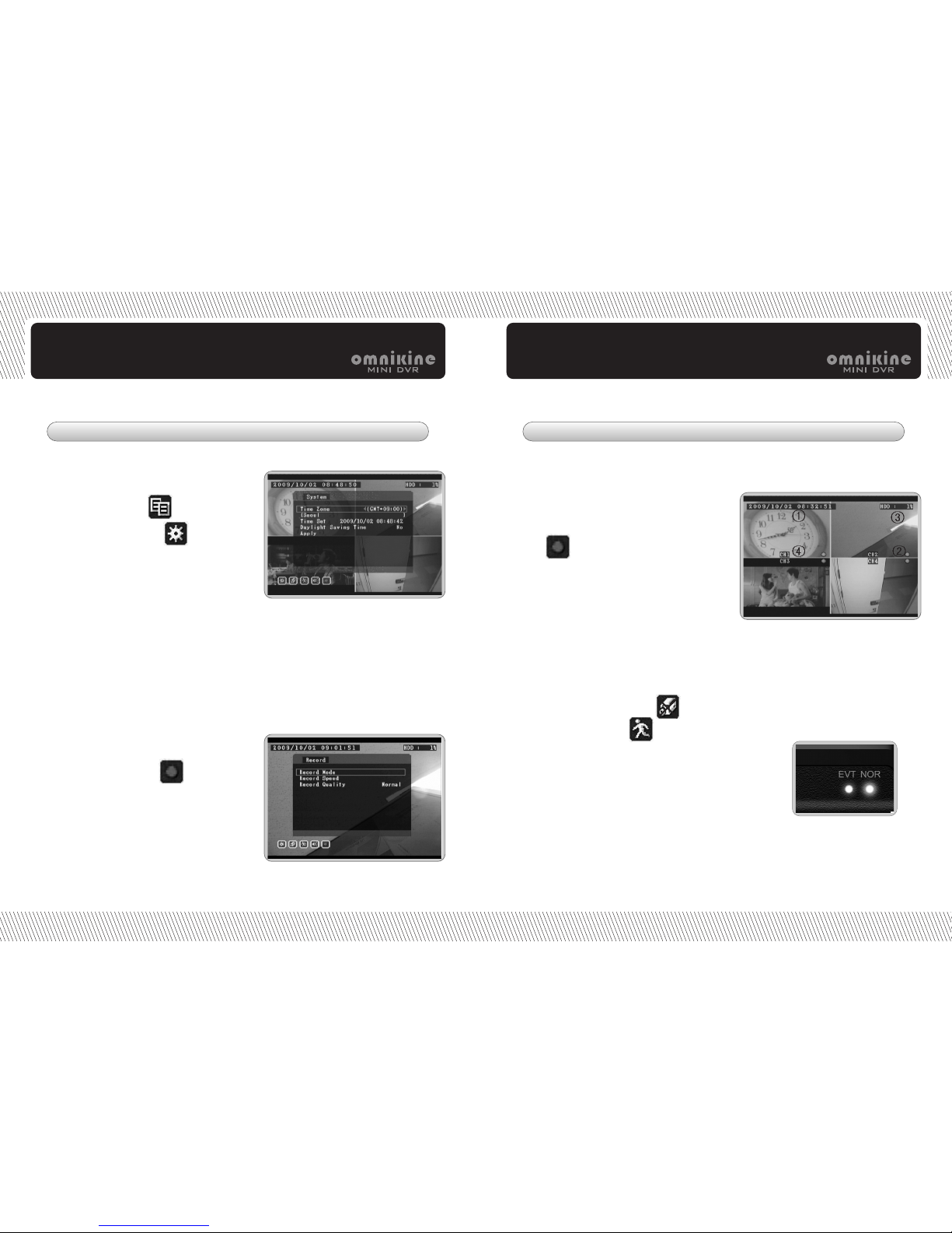
STEP4 Setup
1) Go to record menu
2) Set record mode (normal, event),
speed and quality.
- Press menu setup button.
1) Go to system menu and set
time zone (GMT) to local standrd time.
(ie. Time zone of Korea is GMT+09:00.)
2) Go to time set and press enter button.
Set local time by up/down/right/left
buttons.
1. Date & time setup
2. Record setup
1) NOR is blinking every 1 second : Normal
recording is on.
2) EVT is on or blinking every 1 second : Event recording (or event record setup) is on.
3) NOR & EVT are blinking together : Video is not recorded on HDD. (Need to check
record setup like overwrite menu.)
4) NOR & EVT are blinking together every 0.1 second : It means HDD error or all
channel have no videos.
1) Date and time information : It appears
on the left top of screen.
2) : It shows that recording is on.
3) HDD recording capacity : it is displayed
on the right top of screen.
The percentage is getting higher as
recording time goes up.
4) Channel name : It is on screen.
5) Video loss : The channel with no video
shows as blue, displaying
6) Motion detection : is on when
motion is triggered.
1. Monitor Check
2. LED Check
STEP5 Operation Check
Page 7
Main Features and Specification
Car & Home Security System
15
Car & Home Security System /
Main Features
1. Good design and super slim 4ch DVR
2. Optimized observation system
3. Real time display and recording (Max. M-JPEG 60 fps)
4. Various display mode (1ch display / 4ch split disply)
5. Video loss and motion detection
6. Fast system booting
7. High recording resolution
8. Log list
9. Backup viewer
10. 4ch audio
11. USB and HDD backup
12. Multiple language
13. USB upgrade
Main Features
Page 8
/ Car & Home Security System
16 17
Car & Home Security System /
Main FeaturesMain Features
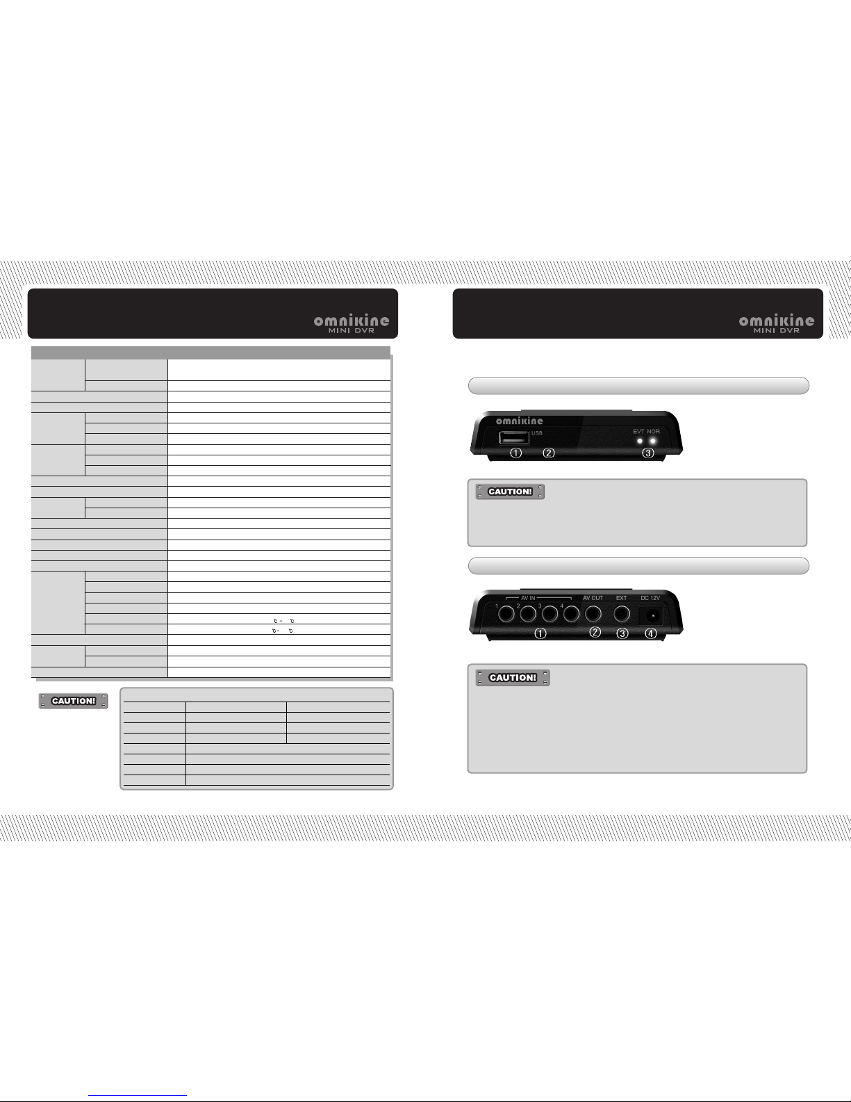
Front Panel
Rear Panel
1. Upgrade and backup
2. Remote controller sensor
3. Recording information LED
1. Camera input
2. Video & audio output
3. RS-232
4. Power inlet
- Use connection cables in package.
-
It may cause DVR to work abnormally when not using connection
cables in package.
- It supports camera power up to max. 250 mA.
-
In case that camera power is over 250 mA, it is required to use its
own power adaptor.
-
Otherwise, it may cause DVR to be damaged and work abnormally.
- Use connection cables in package.
-
It may cause DVR to work abnormally when not using connection
cables in package.
Video Signal
Video Input
4 Channel Input (Phone jack)
NTSC / PAL, 1V 75 Ohm
1 Output (Phone jack)
M-JPEG
Real Time Display / Record / Playback
NTSC-720 X 480 / PAL-704 X 576
Real Time Display
4, 1 screen
NTSC-640 X 224 / PAL-640 X 272
HD1(60fps)
Continuous, Event (motion)
Event, Time
USB memory
4 channel input (Phone jack)
1 channel output (Phone jack)
File Viewer (Backup)
Remote Controller, External Controller
Multi OSD (TBD)
USB
RS-232 (A/S)
Yes
Yes
1~4
Yes
-20
60
0 40
DC 12V, 3.0A
143(W) X 92(H) X 20(D)mm
0.5 kg
FCC, CE, KTL
Video Output
Compression
Multiplex Operation
Resolution
Speed
Mode
Resolution
REC Speed
Mode
Search
Backup
Audio Input
Audio Output
Viewer
System control
Language
System upgrade
Serial interface
Signal Loss Detection
Motion Detection
Motion Sensitivity
Hidden
Storage Temperature
Operation Temperature
Power supply
Dimension
Weight
Approval
Display
Recording
Audio
Others
Mechanical
Specification
PC System Requirments
CPU
Ram Memory
Video Memory
Rseolution
HDD Capacity
OS
Direct
Minimum
INTEL Pentium 4/3.0GHz
1GB
128MB
1280X1024(with 32bit color) or higher
1GBor higher
Windows XP Professional / Windows Vista Business
DirectX 9.0 or higher
Recommendation
Core2duo E6550 or higher
2GB or higher
512MB or higher
Page 9
/ Car & Home Security System
18 19
Car & Home Security System /
Specification Specification
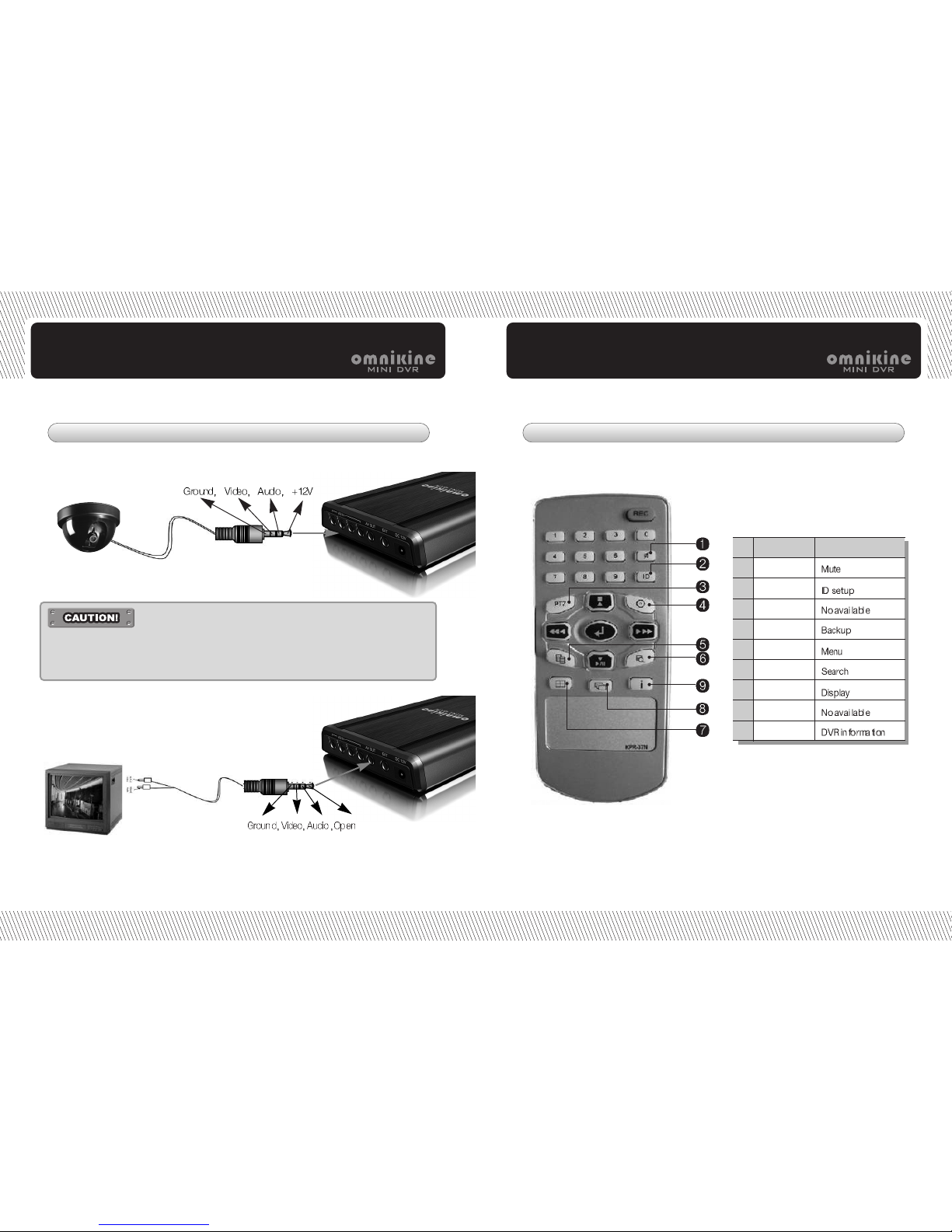
Cable information
1. Camera input cable
2. A/V out cable
Connect DVR to monitor, using A/V output cable in package.
Remote Controller
NAME
Mute
ID
PTZ
BACK UP
MENU
Search
DISPLAY
SEQUENCE
INFO
FUNCTION
NO
1
2
3
4
5
6
7
8
9
- Connect camera with specially designed one jack cable (which can be purchased
from supplier) to DVR and monitor to DVR, using AV out cable in package.
- You can connect normal camera to DVR as well, using optional camera cable.
Page 10
/ Car & Home Security System
20
Specification
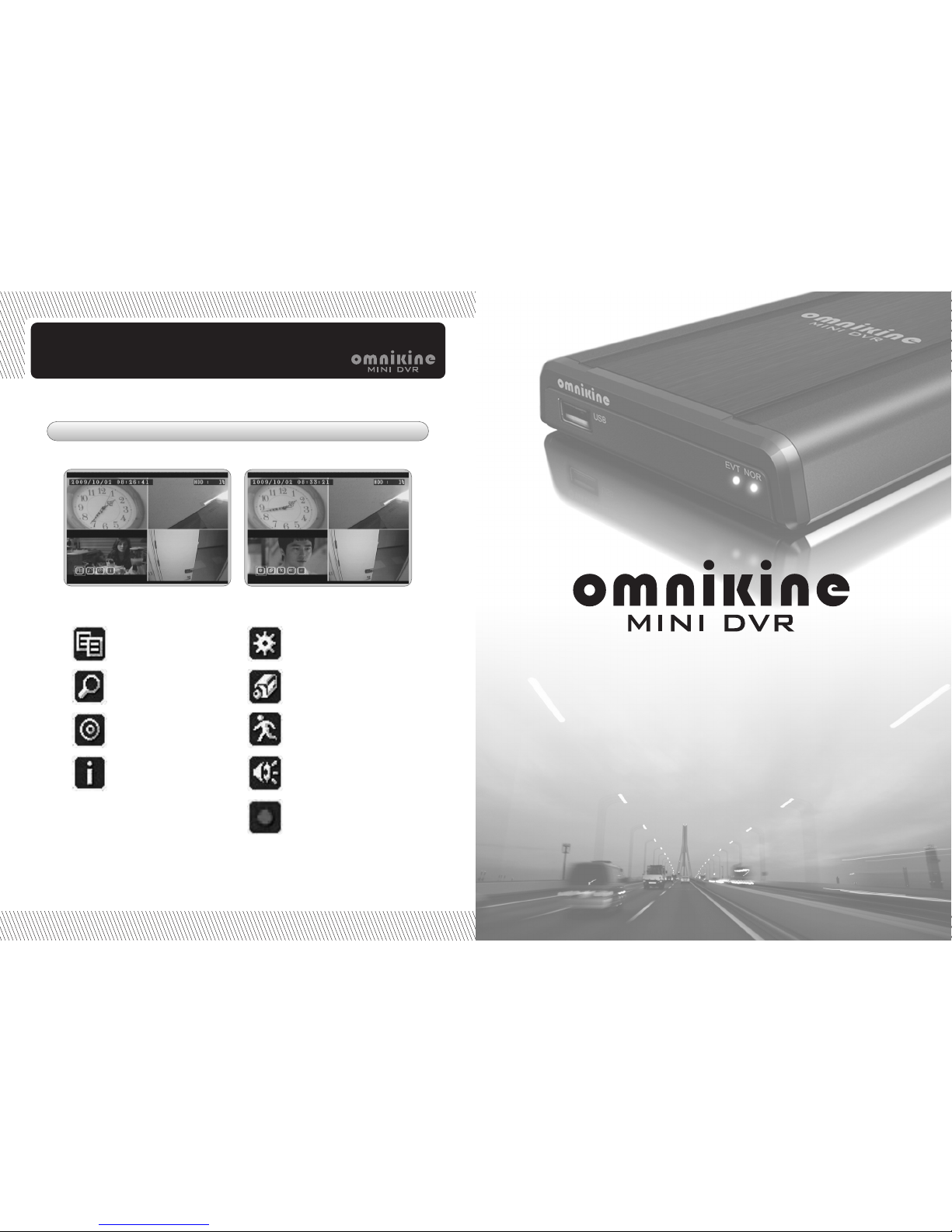
Menu Icon
Menu setup
Search
Backup
DVR Information
System setup
Camera setup
Motion setup
Audio setup
Record setup
Operation
Car & Home Security System
Page 11
/ Car & Home Security System
22 23
Car & Home Security System /
Operation Operation
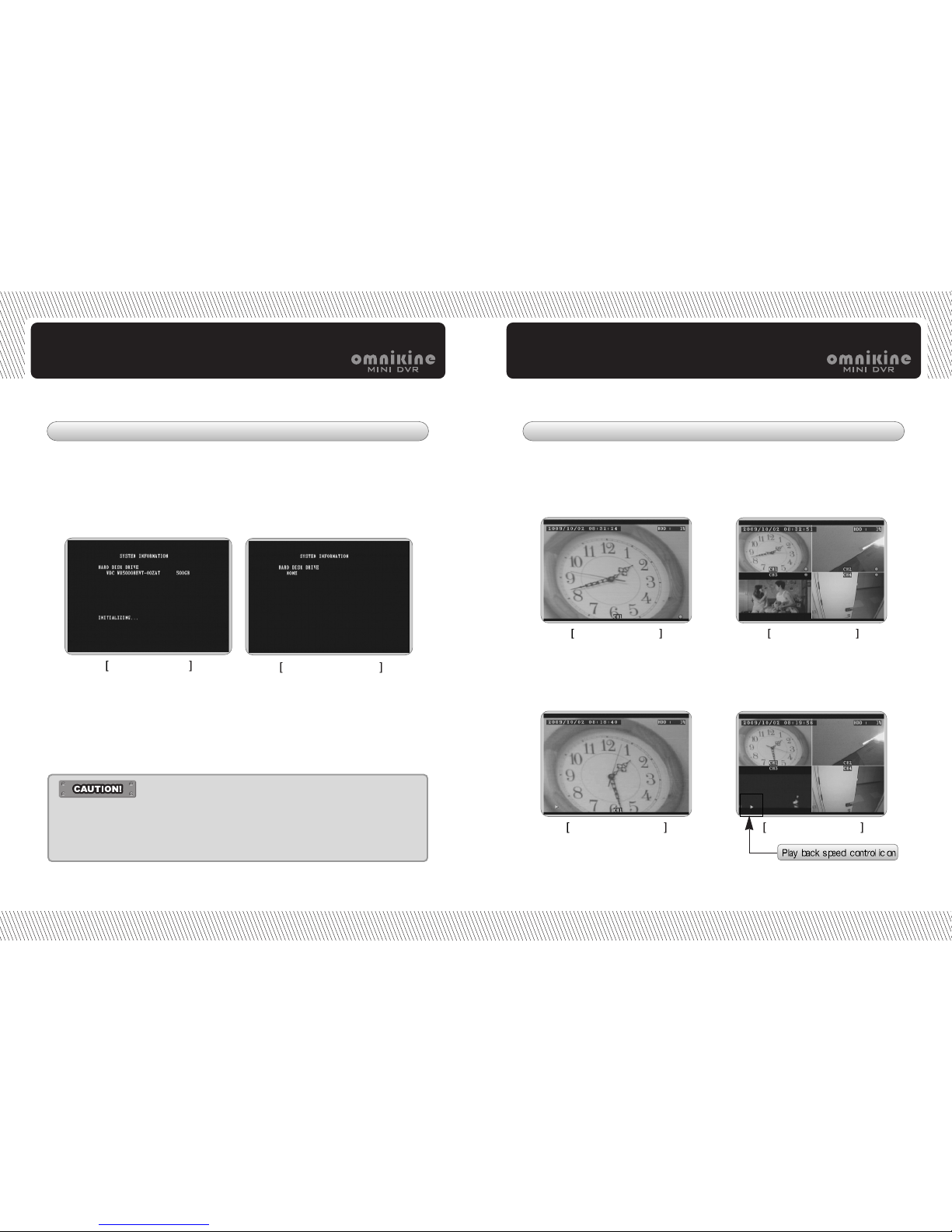
1. Power On 2. Live Display
HDD installation
No HDD Installation
1ch display mode
4ch display mode
1ch playback mode
4ch playback mode
It must be required to use adaptor in package.
1. Connect adaptor in package to DVR.
2. System information shows on screen after connection.
3. Live video appears in 10 seconds after system information and it works as
menu setup.
4. In case of abnormal power supply, menu setup values do not change.
4ch display mode is default and it can be changed to 1ch display mode
by pressing channel buttons.
1. Display Mode (1ch mode, 4ch mode)
Playback mode is same as live display mode but play button icon appears
on the left bottom of screen.
2. Playback
- Adaptor must be connected to DVR after conneting camera and
monitor to DVR first.
- It must be required to use adaptor in package.
- Otherwise, it may cause DVR to be damaged and work abnormally.
Page 12
/ Car & Home Security System
24 25
Car & Home Security System /
Operation Operation
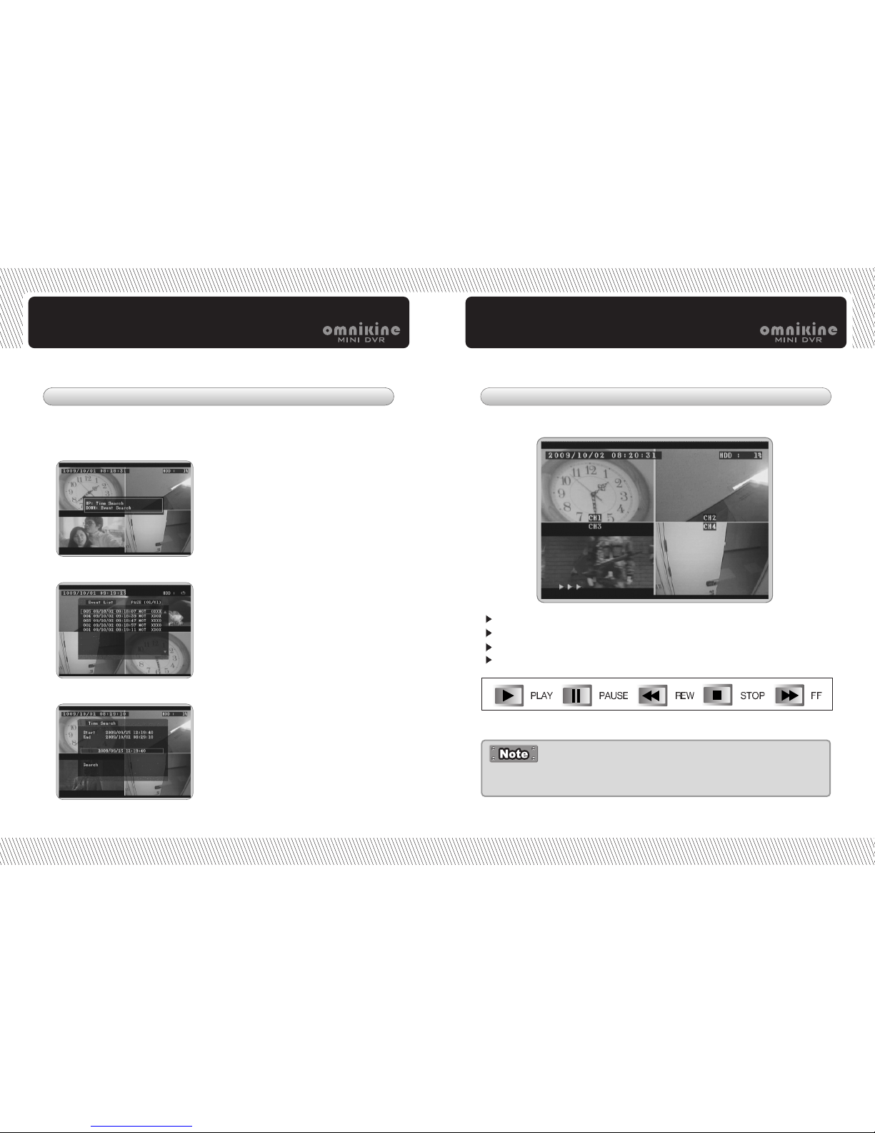
3. Search
Recording data can be searched by normal recording list or event recording list.
Press search button and go to search mode as below.
Select search mode between
time search and event search by
pressing up/down buttons.
Go to recording list and press
enter button.
It plays the selected recording list.
Recording data can be played in various modes.
Press enter button and set the date
and time as want.
After completing data & time input,
press enter button again.
Go down to search and press enter
button.
It plays the recoridng list with the
date and time.
1) Event Search
2) Time Search
4. Playback
Recording data can be played frame by frame by pressing FF/REW
buttons repeatedly in pause mode.
REW icon : It shows recording data is played backward.
PLAY/PAUSE icon : It shows recording data is played or paused.
FF icon : It shows recording data is played forward.
STOP icon : It shows recording data is stopped.
Page 13
/ Car & Home Security System
26
Operation
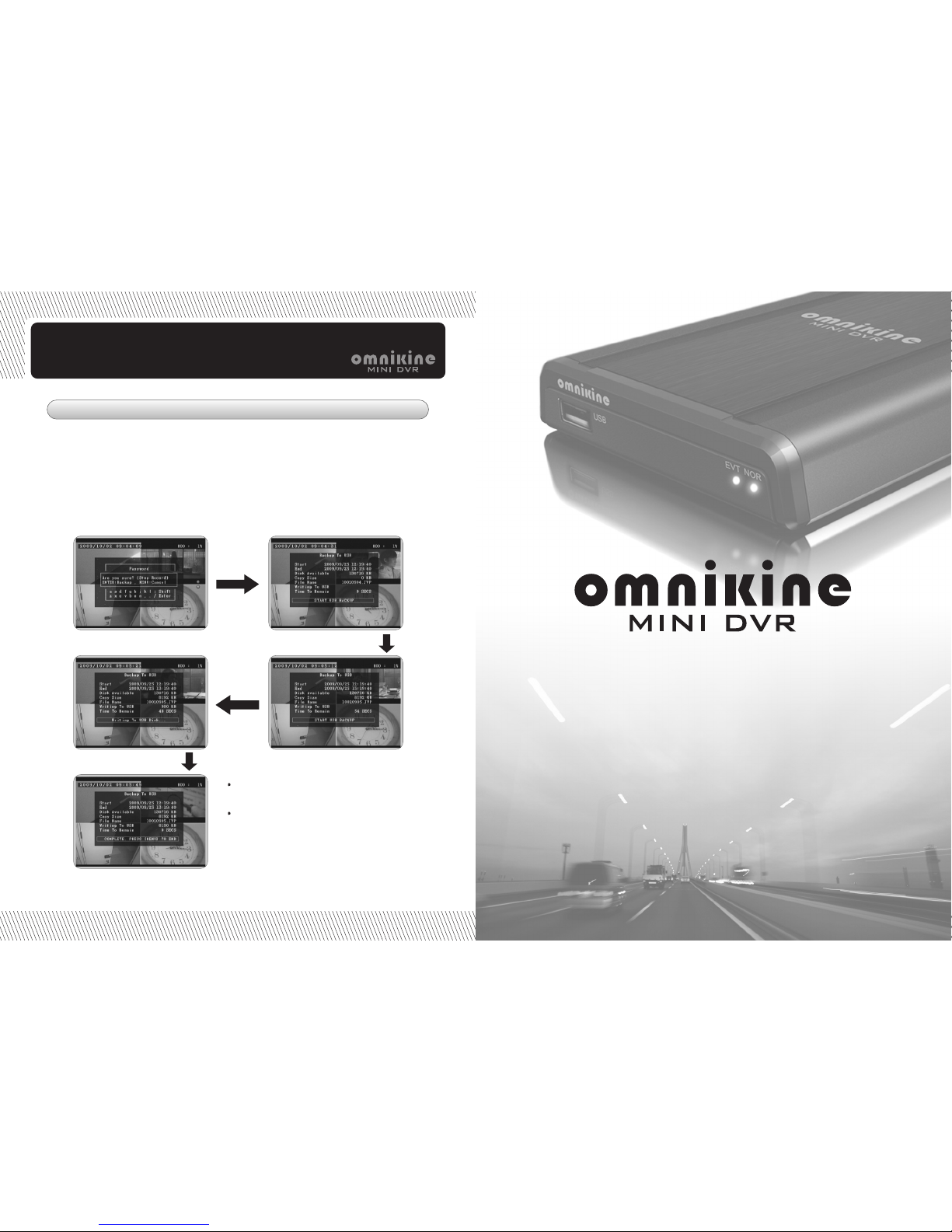
5. Backup
Recording data can be archived to USB memory as backup.
But it stops recording automatically during data backup.
Backup data can be played on backup viewer program provied in package CD.
The recording data in HDD can played on backup viewer as well after
conneting HDD to PC directly through USB to SATA converter.
1. Backup Mode
1. Recording stop notice
2. Backup period setup
4. Writing to USB disk
3. Start USB backup
5. Completed
The backup data in USB can be
played on backup viewer installed in PC.
The recording data in HDD can played
on backup viewer as well after conneting
HDD to PC directly through USB to SATA
converter.
Backup Viewer
Car & Home Security System
Page 14
/ Car & Home Security System
28 29
Car & Home Security System /
Backup Viewer Backup Viewer
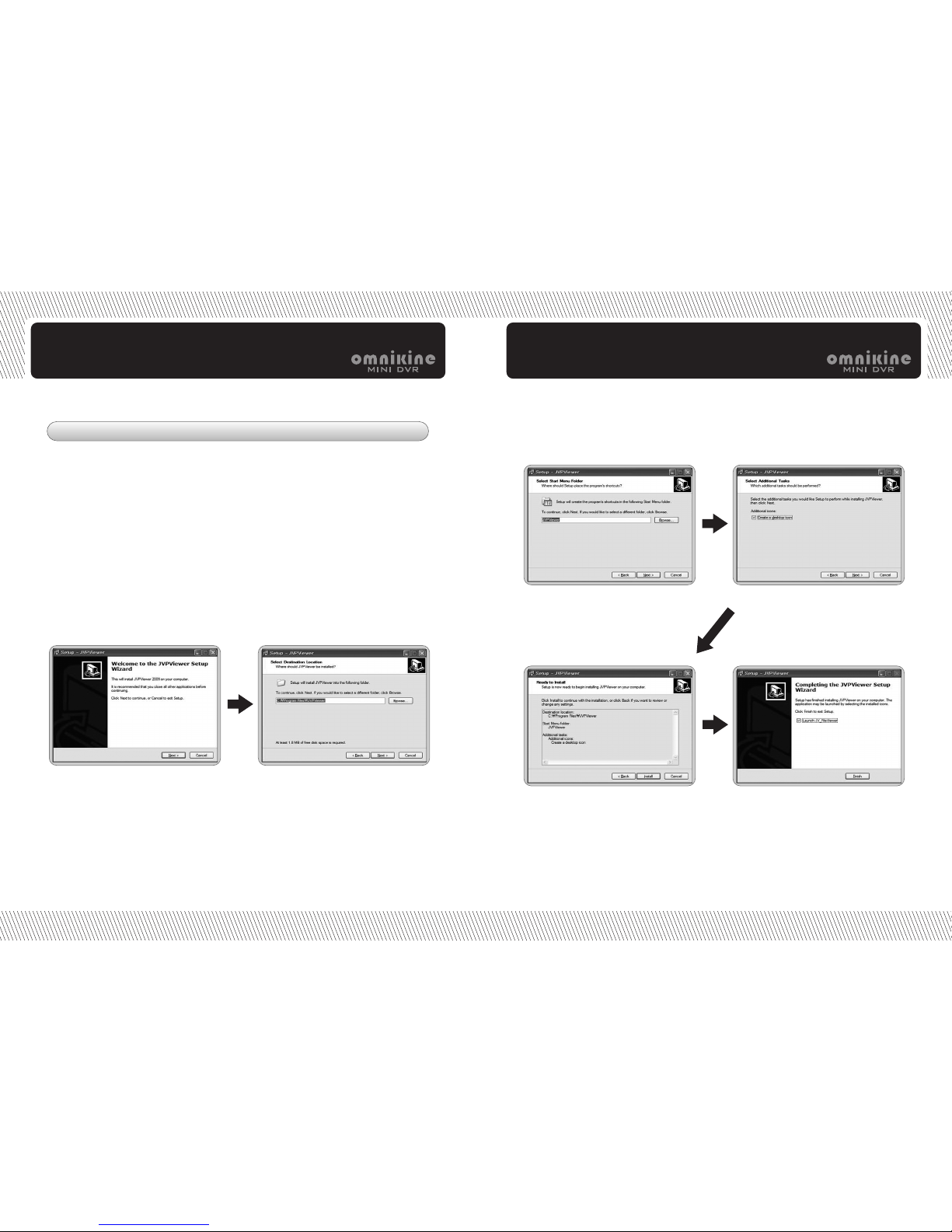
1. Backup Viewer Installation
1. Backup Viewer Download
Backup viewer program is provided in package CD or can be downloaded from
the link as below.
http://www.videonetserver.com/jvp/index.htm
or http://222.231.1.156/jvp/index.htm
Press next button. Select directory.
Change icon name as want. Check if creating a desktop icon.
Show installation information. Complete installation.
Double click JVP Viewer Setup.exe file
Page 15
/ Car & Home Security System
30 31
Car & Home Security System /
Backup Viewer Backup Viewer
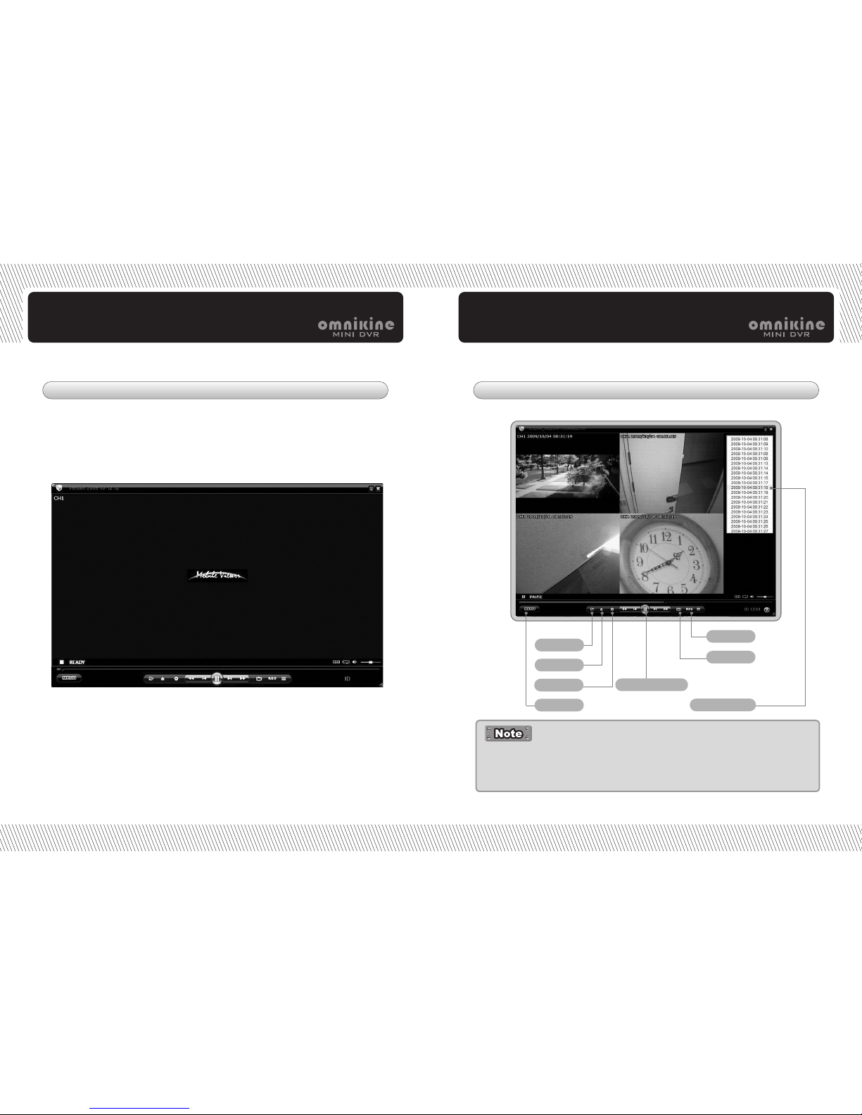
2. Program Open 3. Backup Viewer Function
Capture
Record
Option
Open disk
Playback mode
Playback list
Open file
Menu
-
For more details, donwload backup viewer manual from the link as below.
- http://www.videonetserver.com/jvp/index.htm
- http://222.231.1.156/jvp/index.htm
- It can play backup data in USB memory.
- It can play recording data in HDD as well after conneting HDD to PC
directly through USB to SATA converter.
Page 16
33
Car & Home Security System /
Menu Setup
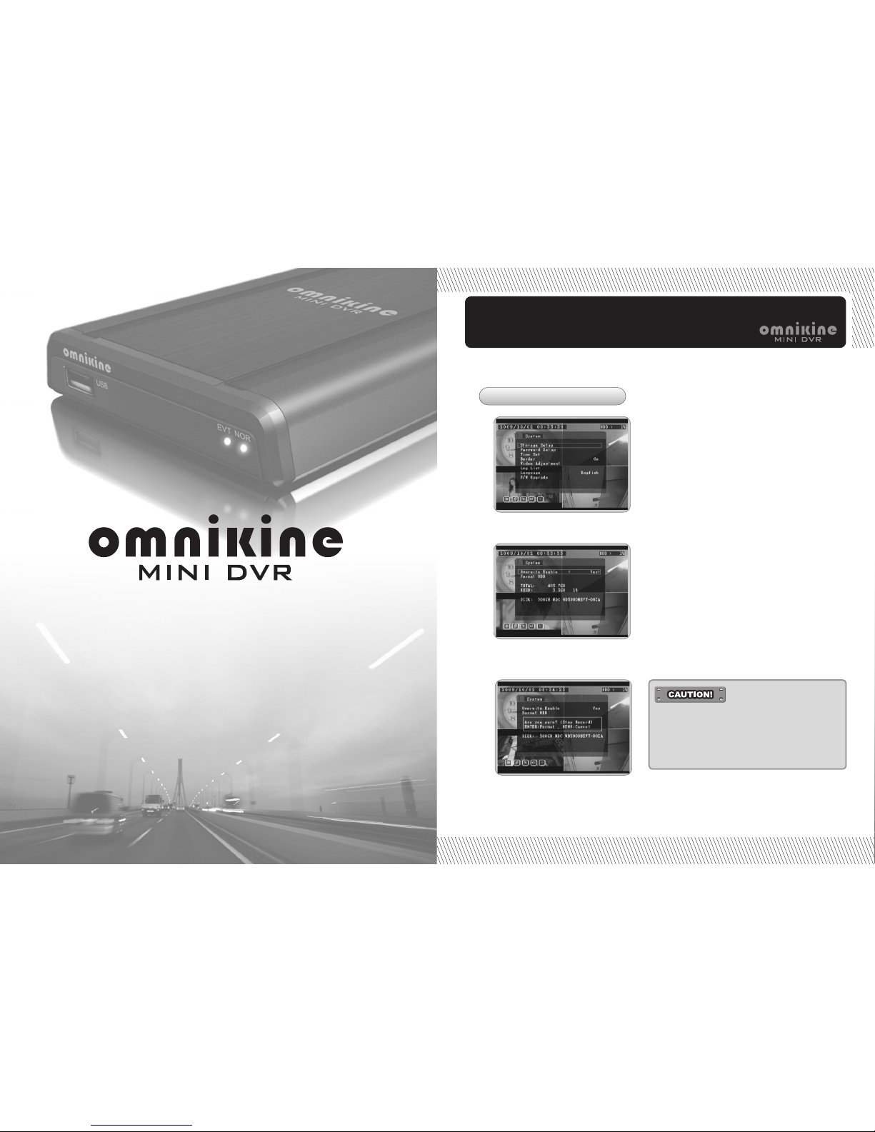
1) Overwrite
2) Format HDD
Menu Setup
Car & Home Security System
1. Storage Setup
- Before formatting HDD, check it
once again.
-
Once HDD is formatted, all recording
data is deleted completely.
Once HDD is full with recording
data, it goes back to the first stage
and record videos from it again.
(Overwrite enable - yes is default.)
If overwrite enable sets to no, it
stops recording once HDD is full
with recording data.
Page 17
/ Car & Home Security System
34 35
Car & Home Security System /
Menu Setup Menu Setup
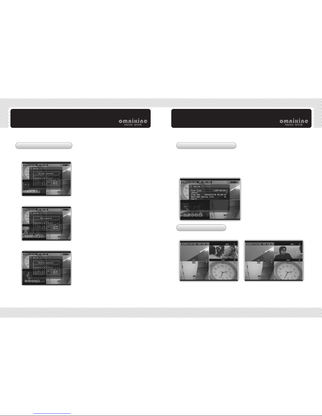
Current password
- Select GMT as your standard time zone.
- Go to time set and set date & time as your local time.
- Press enter button and change date & time.
- After completing date & time setup, go down to apply.
- Press enter button and exit from menu.
Select border on or off.
New password
Confirm password
Border ON
Border OFF
3. Date & time Setup
4. Border Setup
2. Password Setup
Page 18
/ Car & Home Security System
36 37
Car & Home Security System /
Menu Setup Menu Setup
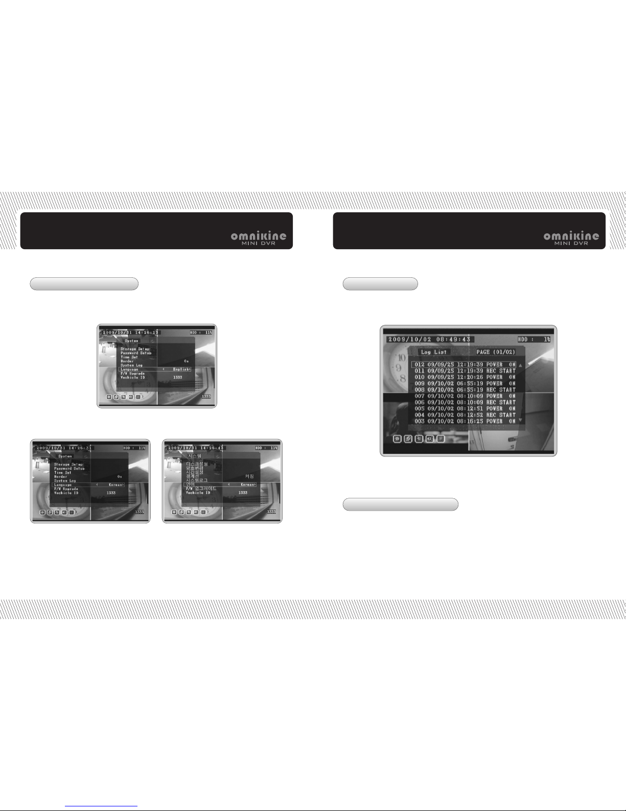
Select one by pressing left/right
buttons.
Press menu button to exit from
menu.
It shows all system operation information like
recording start time.
Go to language menu.
It supports multiple languages.
It shows system operation status with date & time information.
Input car number (4 digits only) and it is displayed on the right bottom of
screen in both of live and playback mode.
5. Language Setup 6. Log List
7. Car Number Setup
Page 19
/ Car & Home Security System
38 39
Car & Home Security System /
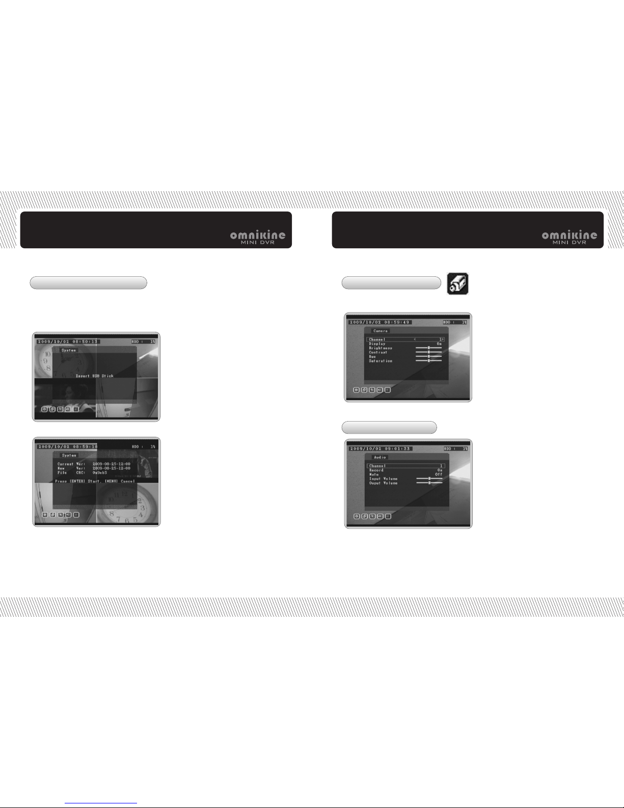
Check if inserting USB memory
properly or not.
Check new firmware version and
press enter button.
System upgrade starts.
Select camera number and optimize
display quality by selecting menu
values.
If setting display to OFF, no video is
recorded.
Setup audio recording, mute and
volume.
If setting record to OFF, no auido is
recorded.
Menu Setup Menu Setup
Download new firmware and upgrade DVR by USB memory.
Inset USB into DVR and follow steps as below.
After upgrade, press i button and check system information.
8. Firmware Upgrade 9. Camera Setup
10. Audio Setup
Page 20
/ Car & Home Security System
40 41
Car & Home Security System /
Menu Setup Menu Setup
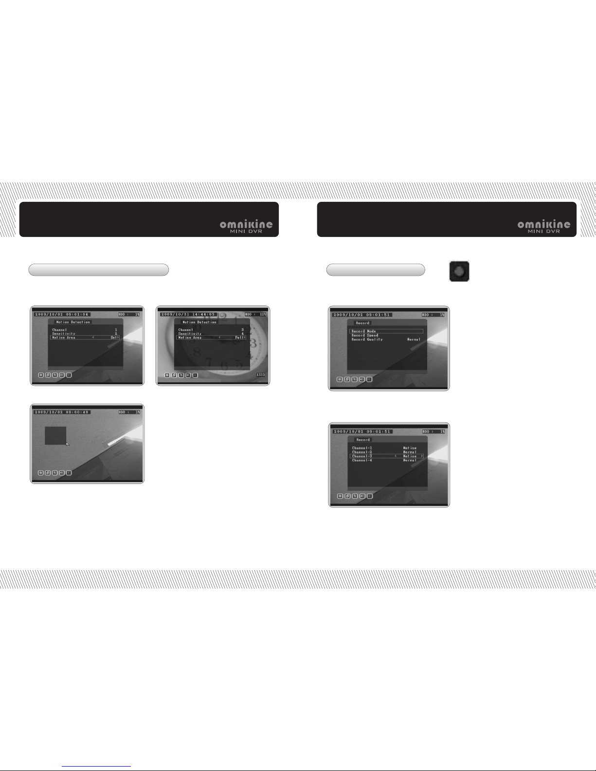
Partial motion area setup Full motion area setup
1) Select "set" in motion area and press enter button.
Go to the start point of area as want.
2) Press enter button and go to the end point of area by pressing
right/down buttons.
3) The area is highlighted in blue.
4) When setting area to full, all area is highlighted in blue.
Setup motion detection with sensitivity and area.
It is recorded in event list once motion is triggered.
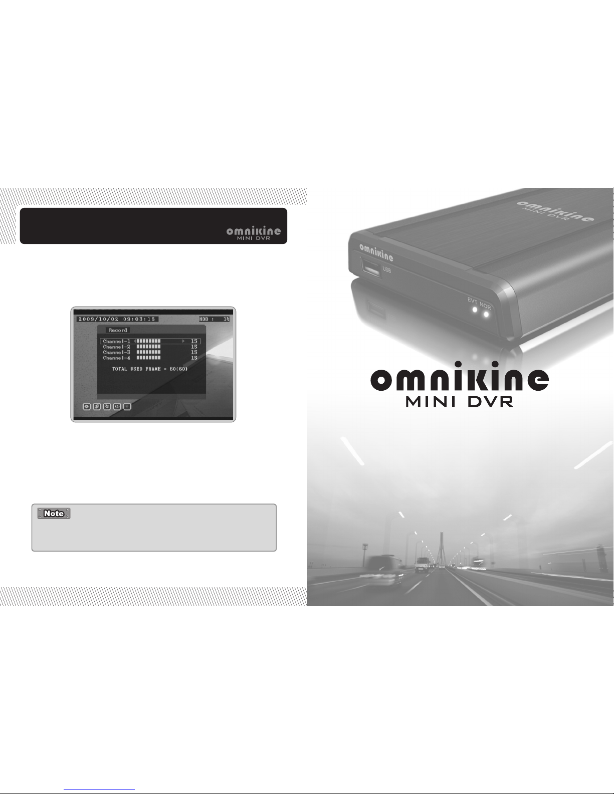
Setup record mode, speed
and quality.
Select normal record or
event record.
12-1.Record Mode
11. Motion Detection Setup 12. Record Setup
Page 21
/ Car & Home Security System
42
Menu Setup
Set record speed up to max. 30fps per channel within total 60fps.
12-2. Record Speed
Select quality among high, normal and low.
12-3. Record Quality
- Record setup is related to HDD recordingperiod.
- When overwrite is on, it records again from the start point
once HDD is full.
Troubleshooting
Car & Home Security System
Page 22
/ Car & Home Security System
44 45
Car & Home Security System /
Troubleshooting Troubleshooting
Check if power cable is correctly connected .
Check if input voltage is correct.
If the system power does not turn on while power cable is correctly
connected, please contact the supplier, or manufacturer.
1. The system power is turn off.
Check if the monitor power cable is properly connected.
Check if the monitor is turned on.
Check if the video output cable of the DVR is properly connected to the monitor.
Unplug the power cable, and plug in again.
2. The system power is turned on, but no video is
displayed on the monitor.
Check if the camera video output is correctly connected to the DVR system.
Check if the power cable is correctly connected on the camera..
Check if the video cable is working well , or not, which is connected to
system from camera.
When video is connected with various systems, weak video signal causes
this kind of problem from video distributor. In this case, the direct
connection with video of relevant camera will find the solution by solving
this matter.
Turn off DVR system, and turn it on again.
3. The camera numbers are displayed on the screen,
but the camera images not displayed.
Check if it is set to “NONE” in the record mode of the record setting mode.
Turn off the DVR, and turn it on again.
The camera video is shown on the screen, but the system
doesn’t record video.
Check if there is a recorded video data when you are trying to search for on the table.
If there is no recorded video data, check if it is set to “NONE” in the
record mode of the recording setting.
Impossible to search for the recorded video.
Check if audio record option is correctly set to the camera you wish to record audio.
Check if audio mute is enabled.
Check if microphone ,and speaker port are correctly connected on the
rear of DVR system.
Check if the connected microphone is properly working.
Check if the connected speaker is properly operating.
6. The audio data is not played in recorded video data.
Check if the camera connected to the system has a problem.
Check if the camera is not damaged by inserting abnormal camera
No. and normal video camera video No. in replacement.
Check if the video system setting is the same as your camera system. Depending
on your area, the camera system can support either PAL, or NTSC. Relying on the
camera video transmission system, video process differs greatly. At this state,
video is seen, but hard to recognize it normally.
7. The color of videos are strange, or video is
shown abnormally.
Check if the video signal output has the problem from camera. Check if the camera
is not damaged by inserting another camera into the working video output in replacement.
Check if it is cut, or cross-wired, or shortened for the video cable to connect the
camera ,and the DVR.
Check if there is a high voltage wire around the video cable connecting the camera
to the DVR system. It can cause the noise problem to decrease video quality.
Check if it is correct for the video cable to connect camera to the DVR system. When
a normal power-supplying cable is used instead of the video cable, screen noise
can be generated.
8. There are much (screen) noise on the image.
Page 23
WARRANTY
The quality of this product is guaranteed by strict quality control
processes, and testing. If the product becomes non-operational, the
warranty may be in operation. The warranty period is valid for 1 year
from the date of purchase.
If the product becomes non-operational, the warranty may be in operation.
The warranty period is valid for 1 year (s) from the date of purchase. Service fee,
and replacement parts will be charged in below cases:
1. Damaged the user’s carelessness.
2. Damaged due to a natural disaster.
3. Damaged due to the user not following the instructions, and cautions written in
the user’s guide.
4. Damaged due to incorrect power voltage, and/or frequency being used.
5. If the Product Warranty sheet is expired.
6. Damaged due to an engineer not employed by supplier, or manufacturer modifying
the system.
If your system is damaged after the expiry of the warranty period, free repair service
will not be available.
If you wish the system to be repaired, service fee, and replacement parts will be
charged.
The Product Warranty Sheet will not be issued again.
The Product Warranty Sheet must be filled on the same day as
the product’s purchase.
This document must be shown in order to receive the free repair service.
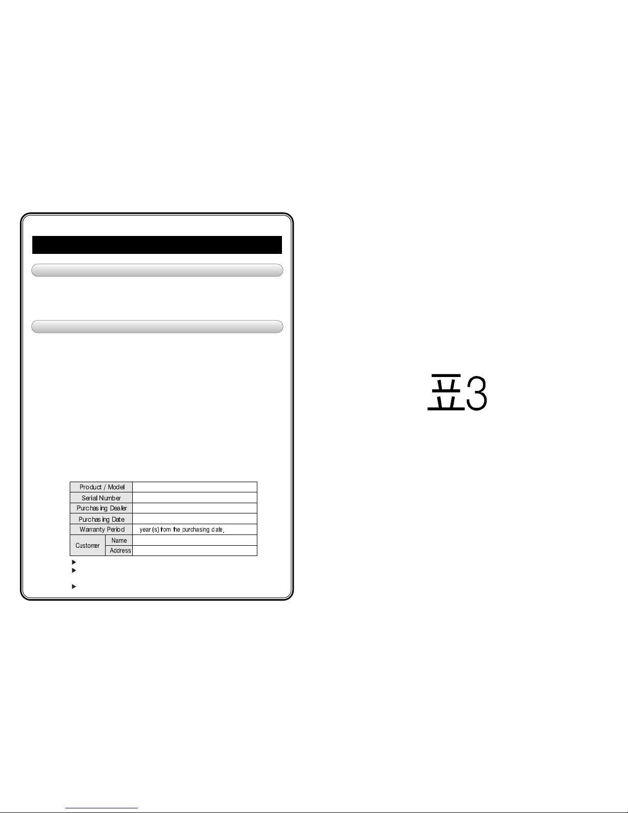
PRODUCT WARRANTY
WARRANTY GUIDE
WARRANTY
 Loading...