

User Manual V1.6
User Manual
-Installation
-Operation
SMP300
SMP600
Omnik New Energy Co.,Ltd.

1
TABLE OF CONTENTS
1. Introduction ............................................................................................................................ 2
2. Safety ...................................................................................................................................... 2
2.1. Symbol illustration ............................................................................................................ 2
2.2. Installation warnings ........................................................................................................ 3
3. Product Description .............................................................................................................. 5
4. Technical data ....................................................................................................................... 6
5. Prepare for installing ............................................................................................................ 7
5.1. Transport and inspect ...................................................................................................... 7
5.2. Check installation environment ..................................................................................... 7
5.3. Installation position ........................................................................................................... 8
6. Mounting and wiring ............................................................................................................. 8
6.1. Install one Micro-inverter ................................................................................................ 8
6.2. Install Several Micro-inverters ..................................................................................... 17
7. Maintenance guide ............................................................................................................. 27
7.1. Routine maintenance ..................................................................................................... 27
7.2. Storage and dismantling ............................................................................................... 28
8. Contact Information ............................................................................................................ 28
Appendix A:User Manual of SMPM100 .............................................................................. 29
1. Product Information ............................................................................................................ 29
1.1. Overview ........................................................................................................................... 29
1.2. Datasheet ......................................................................................................................... 29
2. Monitor installation ............................................................................................................. 30
2.1. Fix the monitor ................................................................................................................. 30
2.2. Connection ....................................................................................................................... 30
2.3. Display ............................................................................................................................... 31
3. Website registration ........................................................................................................... 32
3.1. Enter the website ............................................................................................................ 32
3.2. Choose language ............................................................................................................ 32
3.3. Registration ...................................................................................................................... 33
4. Using the monitor ............................................................................................................... 35
4.1. Login .................................................................................................................................. 35
4.2. Setting ............................................................................................................................... 35
4.3. View the information ....................................................................................................... 39
Appendix B: TEMPLATE FOR MAP OF MICRO-INVERTER INSTALLATION ......... 41
2
1. Introduction
Thank you for using SMP300/600 Micro-Inverter! This Micro-Inverter system is the
world’s most technologically advanced inverter system with benefits of efficient, flexible,
safe and reliable for use in utility-interactive applications.
This system is composed of a group of Micro-inverters that convert direct current (DC)
into alternating current (AC) and feeds it into the electric grid. Different from systems
that photovoltaic modules are subdivided into strings and controlled by one or several
inverters, this system is built for the incorporation of a Micro-inverter for each
photovoltaic module. Each Micro-inverter works independently of the others to
guarantee maximum power of each photovoltaic module. This setup enables direct
control over the production of as single photovoltaic module, consequently improving
the flexibility and reliability of the system.
This manual contains important instructions for the SMP300/600 Micro-inverter and
must be read in its entirety before installing or commissioning the equipment. For safety,
only qualified technician, who has received training or has demonstrated skills can
install and maintain this Micro-inverter under the guide of this document.
2. Safety
IMPORTANT SAFETY INSTRUCTIONS!
PLEASE KEEP THIS INTRODUCTION IN A SAFE PLACE!
2.1. Symbol illustration
The safety symbols used in this manual are list below and illustrated in detail.
Symbol
Usage
Indicates a hazardous situation that can result in
deadly electric shock hazards, other serious
physical injury, or fire hazards.
Indicates directions which must be fully
understood and followed in entirety in order to
avoid potential safety hazards including
equipment damage or personal injury.
This points out that the described operation must
not be carried out. The reader should stop, use
caution and fully understand the operations
explained before proceeding.
3
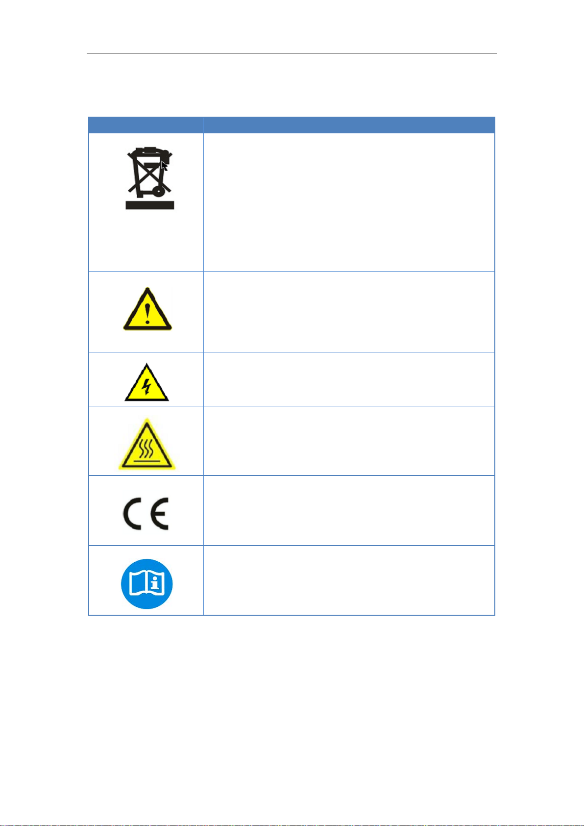
The symbols on the micro-inverter are list below and illustrated in detail.
Symbol
Usage
Treatment
To comply with European Directive 2012/19/EU on
waste Electrical and Electronic Equipment and its
implementation as national law, electrical equipment
that has reached the end of its life must be collected
separately and returned to an approved recycling
facility. Any device no longer required must be returned
to an author zed dealer or approved collection and
recycling facility.
Caution
Do not come within 8 inches (20cm) of the micro-
inverter for any length of time while it is in operation.
Danger of high voltages
Danger to life due to high voltage in the micro-inverter.
Beware of hot surface
The inverter can become hot during operation. Avoid
contact with metal surfaces during operation.
CE mark
The inverter complies with the requirements of the Low
Voltage Directive for the European Union.
Read manual first
Please read the installation manual first before
installation, operation and maintenance.
2.2. Installation warnings
The SMP300/600 Micro-inverter is designed and tested according to international
safety requirements. However, certain safety precautions must be taken when
installing and operating this inverter. The installer must read and follow all instructions,
cautions and warnings in this installation manual
4
➢ All operations including transport, installation, start-up and
maintenance, must be carried out by qualified, trained personnel.
➢ Before installation, check the unit to ensure absence of any transport
or handling damage, which could affect insulation integrity or safety
clearances. Choose installation location carefully and adhere to
specified cooling requirements. Unauthorized removal of necessary
protections, improper use, incorrect installation and operation may
lead to serious safety and shock hazards or equipment damage.
➢ Before connecting the Micro-inverter to the power distribution grid,
contact the local power distribution grid company to get appropriate
approvals. This connection must be made only by qualified technical
personnel .It is the responsibility of the installer to provide external
disconnects switches and Over current Protection Devices (OCPD).
➢ When the photovoltaic array is exposed to light, it supplies a D.C.
voltage to the inverter
➢ Only one photovoltaic module can be connected in the input of the
inverter. Do not connect batteries or other sources of power supply.
The inverter can be used only if all the technical characteristics are
observed and applied.
➢ Do not install the equipment in adverse environment conditions such
as flammable, explosive, corrosive, extreme high or low temperature,
and humid. Do not use the equipment when the safety devices do not
work or disabled.
➢ Use personal protective equipment, including gloves and eye
protection when working.
➢ Inform the manufacturer about non-standard installation conditions.
➢ Do not use the equipment if any operating anomalies are found. Avoid
temporary repairs.
➢ All repairs should be carried out using only qualified spare parts, which
must be installed in accordance with their intended use and by a
licensed contractor or authorized Omnik service representative.
➢ Liabilities arising from commercial components are delegated to their
respective manufacturers.
➢ Anytime the inverter has been disconnected from the power network,
use extreme caution as some components can retain charge sufficient
to create a shock hazard. Prior to touching any part of the inverter use
care to ensure surfaces and equipment are at touch safe temperatures
and voltage potentials before proceeding.
➢ Omnik accepts No liability for damage from incorrect or careless
operation
➢ Electrical Installation & Maintenance shall be conducted by licensed
electrician and shall comply with Australia National Wiring Rules

5
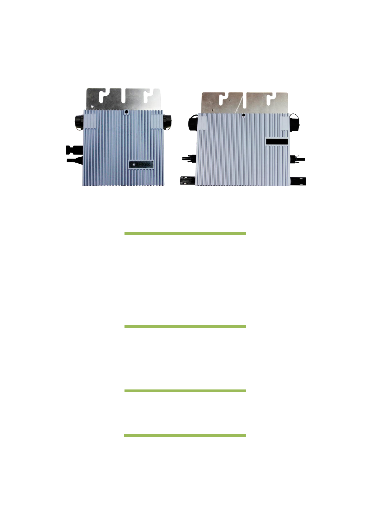
3. Product Description
Fig.1. SMP300
Fig.2. SMP600
Item
Description
A
DC connectors
B
AC connector
C
LED
D
Grounding hole
E
Wall bracket hole
F
Quick install hole
A
B C D
E A B
C D E
F
F

6
4. Technical data
Model
SMP300
SMP600
Input data(DC)
Recommended input power (W)
200~320
2 * 200~320
MPPT voltage range (V)
24~45
24~45
Operating voltage range (V)
18~50
18~50
Maximum input voltage (V)
50
50
Maximum input current (A)
9.5
9.5
Inverter back feed current (A)
0
0
Max. Input Short Circuit Current
(A)
15
15
Output Data (AC)
Max. output power (W)
270
550
Rated output power (W)
250
500
Rated output current (A)
1.09
2.17
Max. output current (A)
1.19
2.39
Maximum output fault current [A]
1.5
3
Maximum output protection
current [A]
20
20
Nominal output voltage (V)
220/230/240
220/230/240
Nominal frequency (Hz)
50/60
50/60
Power factor
>0.99
>0.99
Output current harmonic
distortion
<3%
<3%
Maximum Units per 20A Branch
16
8
Efficiency
Peak inverter efficiency
96.70%
96.70%
CEC weighted efficiency
96.50%
96.50%
Nominal MPPT efficiency
99.80%
99.80%
Night time power consumption
(mW)
<120
<120
Mechanical Data
Dimensions (W×H×D mm)
168×162×34.5
218×174×34.5
Weight [kg]
1.89
2.35
Type of Enclosure
IP67
Cooling
Natural Convection
Environmental Data
Operating Ambient Temperature
Range
-40°C to 65°C
Operating Internal Temperature
Range
-40°C to 85°C

7
Relative Humidity
0-100 % condensing
Environmental Category Rating
Outdoor, suitable to wet locations
Isolation Type
Isolation Transformer
Insulation Level
Reinforced insulation
Max. Operating Altitude without
Derating [m]
2000
Pollution Degree
PD3
Overvoltage Category
OVC II for PV input circuit,
OVC III for mains circuit
Protective class
I
5. Prepare for installing
5.1. Transport and inspect
Omnik packages and protects individual components using suitable means to make
the transport and subsequent handling easier. Transportation of the equipment,
especially by road, must be carried out by suitable ways for protecting the components
(in particular, the electronic components) from violent, shocks, humidity, vibration, etc.
Please dispose the packaging elements in appropriate ways to avoid unforeseen
injury.
It is the customer’s responsibility to examine the condition of the components
transported. Once receiving the Micro-inverter, it is necessary to check the container
for any external damage and verify receipt of all items. Call the delivering carrier
immediately if damage or shortage is detected .If inspection reveals damage to the
inverter, contact the supplier, or authorized distributor for are pair/return determination
and instructions regarding the process.
5.2. Check installation environment
Installation of the equipment is carried out based on the system design and the place
in which the equipment is installed.
➢ The installation must be carried out with the equipment disconnected from the
grid(power disconnect switch open) and with the photovoltaic modules shaded or
isolated.
➢ To avoid unwanted power derating due to an increase in the internal temperature
of the inverter, do not expose it to direct sunlight.
➢ To avoid overheating, always make sure the flow of air around the inverter is not
blocked.
➢ Do not install in places where gasses or flammable substances may be present.
➢ Avoid electromagnetic interference that can compromise the correct operation of
electronic equipment.
➢ To ensure the safety of personnel and equipment needed to mount the PV array
is connected and grounded with other conductor casing.
8
5.3. Installation position
When choosing the position of installation, comply with the following conditions:
Install only on structures specifically conceived for photovoltaic modules (supplied by
installation technicians).
Install Micro-inverter underneath the photovoltaic modules so that they work in the
shade.
If this condition cannot be met, the inverter could undergo derating.
6. Mounting and wiring
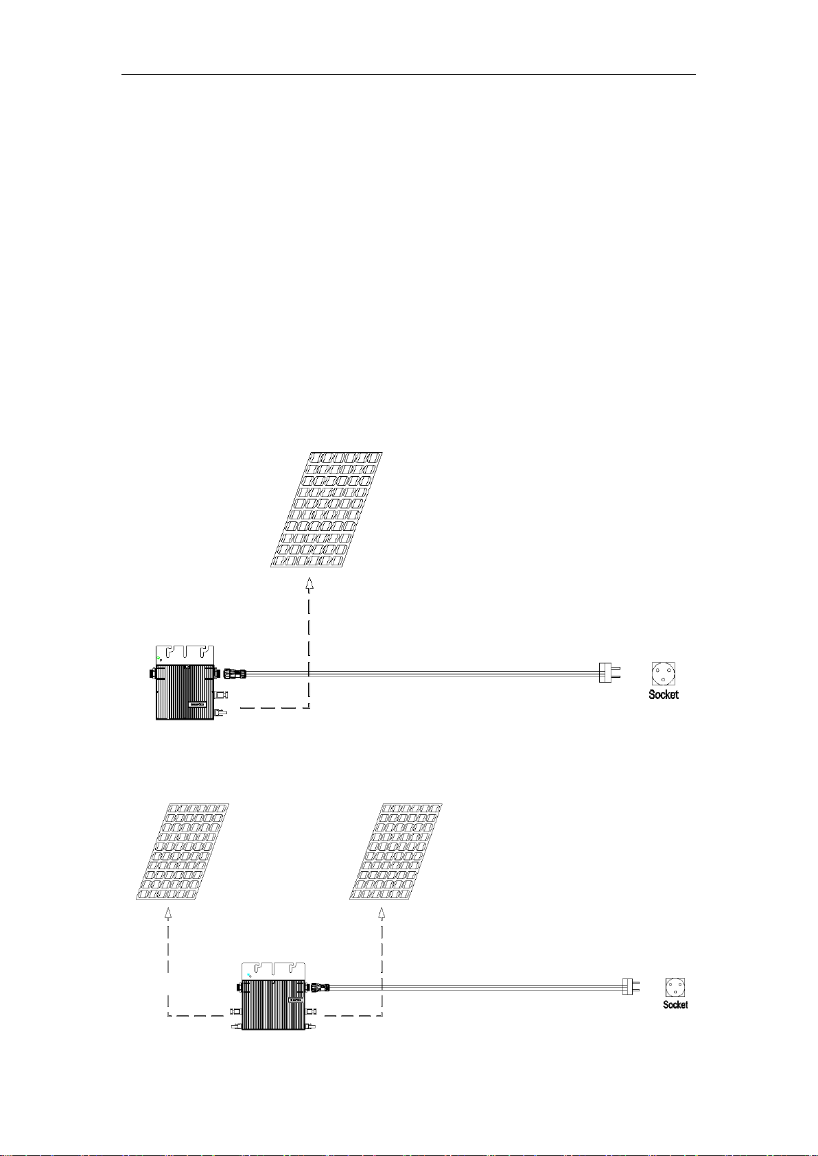
6.1. Install one Micro-inverter
6.1.1. Installing diagram
Fig.3. Assembly Illustration (Only one SMP300)

9
Fig.4. Assembly Illustration (Only one SMP600)
10
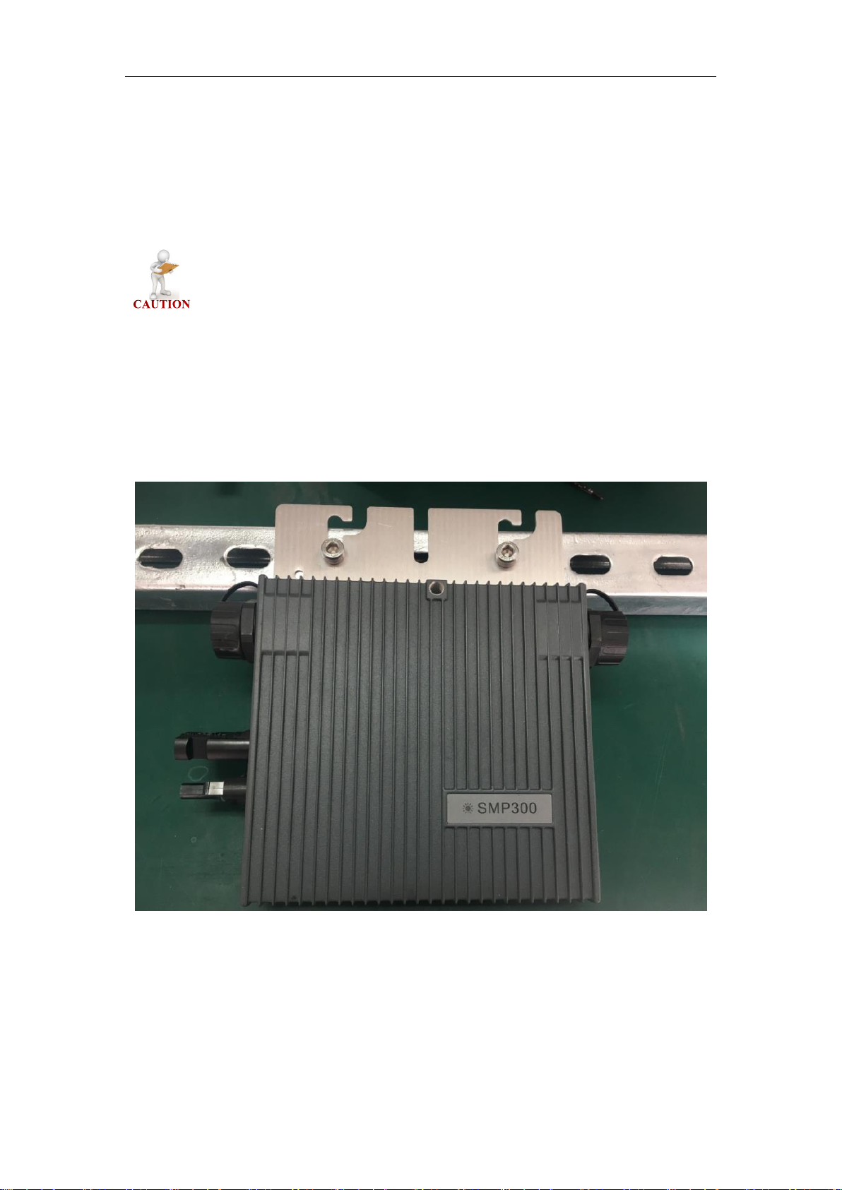
6.1.2. Assembly instruction
Step 1. Install Micro-inverter
Mark the approximate center of photovoltaic module on the frame and install the
Micro-inverter with the LED side facing upwards.
The Micro-inverter must be under the module, out of long-term
exposure to direct sunlight or rain.
First Type of Installation (Wall bracket hole):
There are two wall bracket holes in each Micro-inverter as shown in Fig.1 and
Fig.2.Use a pair of screws and nuts to install the micro-inverter onto the bracket as
shown in Fig.5.
Fig.5. Installation Example (Wall Bracket Hole)

11
Second Type of Installation (Quick install hole):
There is a quick install hole in each Micro-inverter as shown in Fig.1 and Fig.2.
We provide a screw and a metal accessory as shown in Fig.6.Put them on the bracket
as shown in Fig.7.
Fig.6. Screw and Accessory
Fig.7. Installation Position

12
Tighten the screw into the quick install hole on the backside of micro-inverter as
shown in Fig.8.Finally finish the installation as shown in Fig.9.
Fig.8. Tighten the screw
Fig.9. Installation Example (Quick Install Hole)

13
Step 2. Connecting AC End Cables
Connect the AC end cables. We provide an AC connecter for each micro-inverter as
shown in Fig.10.
Fig.10. AC Connecter
Separate the AC connecter as shown in Fig.11.
Fig.11. Separate the AC connecter
Use 12 AWG (4mm2) copper wire for AC end cables. Use only solid wire or stranded
wire.
The definition of the AC connecter is shown in Fig.12.
Port 1(Brown/Red): Live
Port2(Yellow-Green): Ground
Port3(Blue/Black): Neutral

14
Fig.12. Definition of the AC connecter
After finishing wiring ,reassemble the AC connector as shown in Fig.13.
Fig.13. Reassemble the AC connector
Port 1
Port3
Port 2

15
Open the protective cover of the connector as shown in Fig.14. Plug the AC connectors
of the AC End Cable into the micro-inverter as shown in Fig.15. Make sure the
protective cover of the unused AC connector to be closed.
Fig.14. Open the protective cover of the connector
Fig.15. Connect AC Cable of Micro-inverter
To prevent electrical hazards, all the connection operations must be
carried out with the equipment disconnected from the grid.
Pay special attention and ensure not to reverse the phase with the neutral!

16
The installation technician is responsible for selecting a cable with the
appropriate length and cross section.
Step 3. Install Photovoltaic Modules
Install the photovoltaic modules, and connect the DC cables of the modules to the
corresponding DC input side of the Micro-inverter.
Fig.16. Connect DC Cables
The recommended installation needs keeping the Micro-inverters
underneath the photovoltaic modules, so that the Micro-inverters can
operate in the shade. Direct sunlight may cause damage to the Microinverters.
Each module must be connected to the Micro-inverters with a DC
cable having a length of less than 3m.
Check the LED on the side of the micro-inverter. The LED flashes green and red at
start up.
LED
Indicates
Flashing Red
Waiting for connecting to the power grid. (wait for 3-5 mins)
Flashing Green
Working properly.
The higher efficiency is, the faster LED will flash.
DC Cable From
PV Module
DC Cable of
Micro inverter

17
6.2. Install Several Micro-inverters
6.2.1. Installing diagram
Fig.17. Assembly Illustration (Install SMP300 at Each cable section)
Fig.18. Assembly Illustration (Install SMP600 at Each cable section)
Fig.19. Assembly Illustration (Photovoltaic System)

18
6.2.2. Assembly instruction
Step 1. Install Micro-inverter
Mark the approximate center of each photovoltaic module on the frame and
install the Micro-inverter with the LED side facing upwards.
Observe the certification documents concerning the maximum
number of Micro- inverters permitted for installation at each cable
section!
Type
Numbers for each cable section
SMP300
16
SMP600
8
The Micro-inverter must be under the module, out of long-term
exposure to direct sunlight or rain.
Make sure the installation position of micro-inverter meet the
requirements of AC cables.
Type
AC Cable
SMP300
1.1 m
SMP600
2.1 m
First Type of Installation (Wall bracket hole):
There are two wall bracket holes in each Micro-inverter as shown in Fig.1 and
Fig.2.Use a pair of screws and nuts to install the micro-inverter onto the bracket as
shown in Fig.20.

19
Fig.20. Installation Example (Wall Bracket Hole)
Second Type of Installation (Quick install hole):
There is a quick install hole in each Micro-inverter as shown in Fig.1 and Fig.2.
We provide a screw and a metal accessory as shown in Fig.21.Put them on the bracket
as shown in Fig.22.
Fig.21. Screw and Accessory

20
Fig.22. Installation Position
Tighten the screw into the quick install hole on the backside of micro-inverter as shown
in Fig.23.Finally finish the installation as shown in Fig.24.
Fig.23. Tighten the screw

21
Fig.24. Installation Example (Quick Install Hole)
Step 2. Install AC Junction Box
Install an junction box if needed.
Choose a suitable model of air-switch according to the limit current of each cable
section.
Install a monitor device (SMPM100) and a PLC filter in the junction box if needed.
Provide an AC connection from the AC junction box back to the electricity network
connection using equipment and practices as required by local jurisdictions.
Fig.25. Install AC Junction Box

22
Step 3. Connect AC Cable of Micro-inverter
Open the protective cover of the connector as shown in Fig.26. Plug the AC connectors
of the AC Cable into two connectors of different micro-inverters to form a continuous
AC branch circuit as shown in Fig.27. Make sure the protective cover of the unused
AC connector to be closed. (Especially the last micro-inverter)
Fig.26. Open the protective cover of the connector
Fig.27. Connect AC Cable of Micro-inverter
Step 4. Connecting AC End Cables to Junction Box
Connect the AC end cables coming from each cable section to the junction box.
We provide an AC connecter with each micro-inverter as shown in Fig.28.

23
Fig.28. AC Connecter
Separate the AC connecter as shown in Fig.29.
Fig.29. Separate the AC connecter
Use 12 AWG (4mm2) copper wire for AC end cables. Use only solid wire or stranded
wire.
The defination of the AC connecter is shown in Fig.30.
Port 1(Brown/Red): Live
Port 2(Yellow-Green): Ground
Port 3(Blue/Black): Neutral
Fig.30. Definition of the AC connecter
Port 1
Port 3
Port 2

24
After finishing wiring ,reassemble the AC connector as shown in Fig.31.
Fig.31. Reassemble the AC connector
To prevent electrical hazards, all the connection operations must
be carried out with the equipment disconnected from the grid.
All the external connections to the insulated junction box (caps,
adapters, etc.)Must be made with securely-sealed Omnik components.
Pay special attention and ensure not to reverse the phase with the
neutral!
The installation technician is responsible for selecting a junction box
with the appropriate dimensions and insulation.

25
The installation technician is responsible for selecting a cable with
the appropriate length and cross section.
Step 5. Create an Installation Map
Peel the removable serial number label from each micro-inverter. The position of the
label is shown as below. The DC inputs of SMP600 are identified by A and B. The left
input is A and the right one is B, shown as above.
Fig.32. Serial Number Label (SMP300)
Fig.33. Serial Number Label (SMP600)
Affix the serial number label to the respective location on the installation map (found
in the Appendix of this manual).
A
B

26
Fig.33. System Map (SMP600)
Step 6. Install Photovoltaic Modules
Install the photovoltaic modules, and connect the DC cables of the modules to the
corresponding DC input side of the Micro-inverter.
Fig.34. Connect DC Cables
The recommended installation needs keeping the Micro-inverters
underneath the photovoltaic modules, so that the Micro-inverters can
operate in the shade. Direct sunlight may cause damage to the Microinverters.
Each module must be connected to the Micro-inverters with a DC
cable having a length of less than 3m.
DC Cable From
PV Module
DC Cable of
Micro inverter
A
A B B

27
Check the LED on the side of the micro-inverter. The LED flashes green and red at
start up.
LED
Indicates
Flashing Green
Working properly.
The higher efficiency is, the faster LED will
flash.
Flashing Red
Waiting for connecting to the power grid.
Step 7. Energize the System
If applicable, turn on the AC disconnect or circuit breaker for the branch circuit.Turn on
the main utility-grid AC circuit breaker. Your system will start producing power after
about a two-minute wait time.
7. Maintenance guide
7.1. Routine maintenance
➢ Only authorized personnel are allowed to carry out the maintenance operations
and are responsible to report any anomalies.
➢ Always use the personal protective equipment provided by the employer when
carry out the maintenance operation.
➢ During normal operation, check that the environmental and logistic conditions are
correct. Make sure that the conditions have not changed over time and that the
equipment is not exposed to adverse weather conditions and has not been
covered with foreign bodies.
➢ DO NOT use the equipment if any problems are found, and restore the normal
conditions after the fault removed.
➢ Conduct an annual inspection on various components, and clean the equipment
with a vacuum cleaner or special brushes.
➢ Firmware version can be queried by monitoring system.
Do not attempt to dismantle the Micro-inverter or make any internal
repairs! In order to preserving the integrity of safety and insulation,
the Micro-inverters are not designed to allow internal repairs!
Maintenance operations must be carried out with the equipment
disconnected from the grid (power switch open) and the photovoltaic
modules obscured or isolated, unless otherwise indicated.
For cleaning, DO NOT use rags made of filamentary material or
corrosive products that may corrode parts of the equipment or
generate electro static charges.

28
Avoid temporary repairs. All repairs should be carried out using only
genuine spare parts.
7.2. Storage and dismantling
➢ If the equipment is not used immediately or is stored for long periods, check that
it is correctly packed. The equipment must be stored in well-ventilated indoor
areas that do not have characteristics that might damage the components of the
equipment.
➢ Take a complete inspection when restarting after a long time or prolonged stop.
➢ Please dispose the equipment properly after scrapping, which are potentially
harmful to the environment, in accordance with the regulations in force in the
country of installation.
8. Contact Information
Omnik New Energy Co., Ltd. (Headquarter)
Address: Third Floor, Building 3, No.63 Weixin Road, SIP, Suzhou, China
Tel: +86-512-6956-8216
Fax: +86-512-6295-6682
E-mail: sales @omnik-solar.com
sevice@omnik-solar.com
Website: www.omniksolar.com
Omnik Netherlands Office
Address: De liesbosch 82-A, 3439 LC Nieuwegein, The Netherlands
Tel: +31 30265 7845
E-mail: service@omnik-solar.com
Benelux Service Center
Address: Nokweg 3B, 2451 AL Leimuiden, The Netherlands
Tel: +31 (0)85 06 43 068
Email: info@omnikservice.nl
Website: www.omnikservice.nl

29
Appendix A:User Manual of SMPM100
1. Product Information
1.1. Overview
The monitor is shown in the picture below.
1.2. Datasheet
Interface
PLCC
Proprietary
Ethernet
RJ45
RS485
RJ45
Capacity
Numbers of devices connected
Monitor up to 40 units PV models*
Power Requirements
AC Supply
220V/230V/240V;50Hz/60Hz
Power Consumption
1W
Object
Description
A
network cable
B
monitor
C
electrical wire

30
Mechanical Data
Cooling
Natural convection no fans
Ambient Temperature Range
-40℃ ~ +65℃
Enclosure Environment Rating
IP65
Features
Compliance
CE
Warranty
5 Years
*The device can monitor up to 40 units PV models.
2. Monitor installation
2.1. Fix the monitor
The length of the network cable is 1.8 meters and the length of the electrical wire is
1.4 meters. Select the appropriate location to install monitor.
Object
Length
network cable
1.8m
electrical wire
1.4m
As shown below, hang up the monitor after twisting the screw.
2.2. Connection
On the left is the RJ45, which is connected to modem, and on the right is the power
cord, which is directly connected to the power supply.

31
2.3. Display
When the monitor is used normally, the LED will flash.
State
Description
LED light on
run
LED light off
quit
LED

32
3. Website registration
3.1. Enter the website
Type “ www.smpsolar.com ” in explorer address and enter the following interface.
3.2. Choose language
Choose the website language in the top right corner. As shown in the picture below,
Chinese and English can be chosen.

33
3.3. Registration
Click “Registration” to register and fill in the information as required.
Please fill out e-mail address and password. Then click “next”.

34
Please fill in your info and click “complete” to finish the registration.
① Type your name in Site name.
② Fill in Country, Province/State and City truly.
③ System Size is the power of the inverter purchased.
④ FIT is filled in according to the local electricity price.
⑤ Ask the installer about FIT which is the number of the monitor.

35
4. Using the monitor
4.1. Login
Type “http://www.smpsolar.com” in explorer address and enter the following
interface. Then sign in the account.
4.2. Setting
After finishing the installation of the system, when the weather is well and all the

36
inverters are working normally, you can start setting the monitors.
① Click the setting and the device.
② Click the “add” and type in the S/N of the monitor. Then click the ok.

37
③ Click the “netting” button, and the monitor starts to search for the micro-
inverter, which takes 5 minutes to complete.
④ Check the S/N of the micro-inverter. You can delete the inverter which you
don’t want to monitor.

38
⑤ Click the overview. Left-click and drag the pattern. You can arrange the
pattern according to the position of the inverters and click the save.
⑥ These settings will keep records in the system.

39
4.3. View the information
Click the power to look at the accurate real-time output power in a day.
Click the energy to look at the amount of produced electricity in a day.

40
More information can be acquired by clicking the history.

41
Appendix B: TEMPLATE FOR MAP OF MICRO-INVERTER INSTALLATION
Customer Information:
Please affix the extra label that
comes from each inverter, on
the appropriate position on this
diagram.
1
2
3 4 5
A
B
C
D
E
 Loading...