

Omnik Omniksol-2k-TL3-S, Omniksol-2.5k-TL3-S, Omniksol-3K-TL3-S User Manual
User Manual V1.5
User Manual
-Operation
Omniksol-2k-TL3-S
Omniksol-3k-TL3-S
Omnik New Energy Co.,ltd
-Installation
Omniksol-2.5k-TL3-S


Catalog
1.
Notes on this manual .................................................................................................................... 3
1.1 Scope of Validation ................................................................................................................................ 3
1.2 Symbols Used ......................................................................................................................................... 3
1.3 Target Group............................................................................................................................................ 4
2. Preparation .................................................................................................................................... 5
2.1 Safety Instructions ................................................................................................................................. 5
2.2 Explanations of Symbols on Inverter ................................................................................................ 6
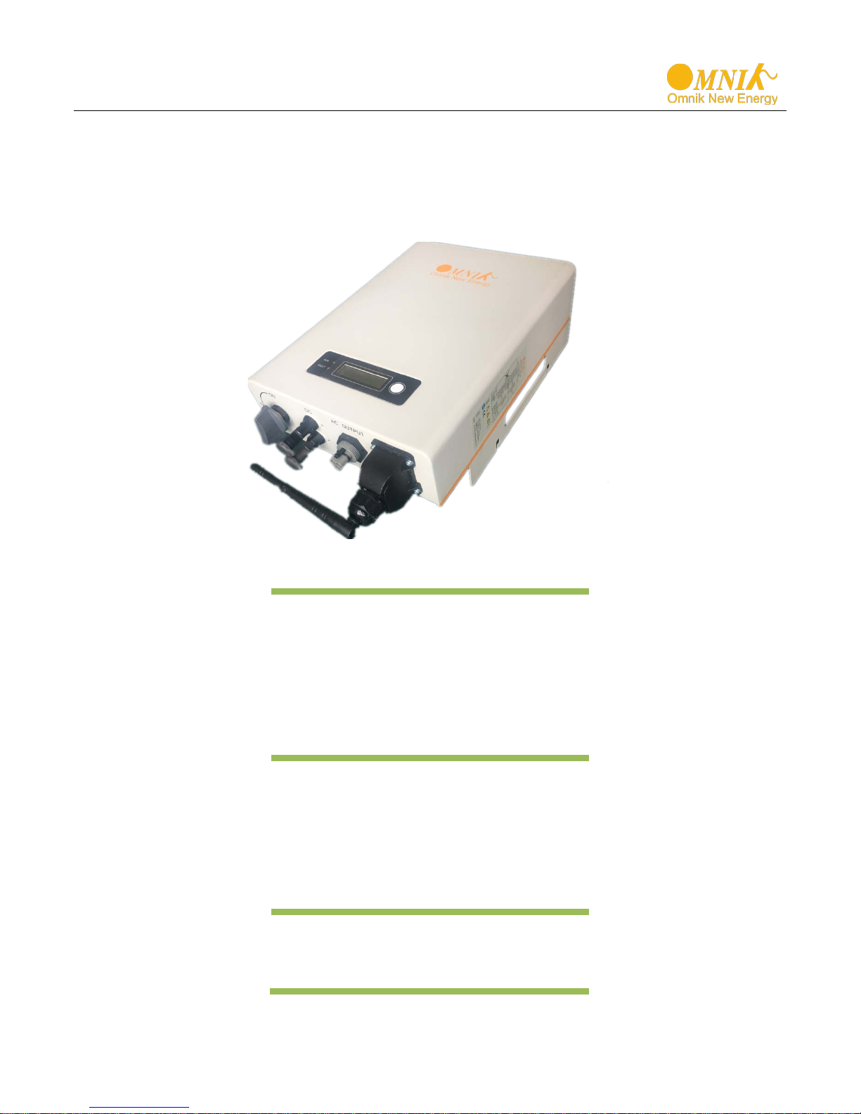
3. Product Information...................................................................................................................... 8
3.1 Overview ................................................................................................................................................... 8
3.2 Major Characteristics ............................................................................................................................ 9
3.3 Datasheet ................................................................................................................................................10
4. Packing checklist ........................................................................................................................ 12
4.1 Assembly parts .....................................................................................................................................12
4.2 Product Appearance ............................................................................................................................13
4.3 Product Identification ..........................................................................................................................14
4.4 Further Information ..............................................................................................................................14
5. Installation ................................................................................................................................... 15
5.1 Safety .......................................................................................................................................................15
5.2 Mounting Instructions .........................................................................................................................16
5.3 Safety Clearance ...................................................................................................................................17
5.4 Mounting Procedure ............................................................................................................................17
5.5 Safety lock ..............................................................................................................................................19
6. Electrical Connection ................................................................................................................. 20
6.1 Safety .......................................................................................................................................................20
6.2 AC Side Connection ............................................................................................................................20
6.3 DC Side Connection ............................................................................................................................23
7. Display ......................................................................................................................................... 28
7.1 LCD Panel ...............................................................................................................................................28
7.2 LCD Display ...........................................................................................................................................29
7.3 Instructions of Safety Standard selection when power-up .......................................................30
1

7.4 State Information ..................................................................................................................................31
8. Recycling and Disposal .............................................................................................................. 32
9. Troubleshooting ......................................................................................................................... 33
10. Abbreviation ................................................................................................................................ 34
11. Contact ........................................................................................................................................ 35
2
CAUTION
CAUTION indicates a hazardous condition which, if not avoided,
can result in minor or moderate injury.
WARNING
WARNING indicates a hazardous situation which, if not
DANGER
DANGER indicates a hazardous situation which, if not
avoided, will result in death or serious injury.
1. Notes on this manual
1.1 Scope of Validation
The main purpose of this User’s Manual is to provide instructions and detailed
procedures for installing, operating, maintaining, and troubleshooting the following three
types of Omnik New Energy-Solar Inverters:
Omniksol-2k-TL3-S
Omniksol-2.5k-TL3-S
Omniksol-3K-TL3-S
Please keep this user manual all time available in case of emergency.
1.2 Symbols Used
avoided, can result in death or serious injury or moderate injury.
3
NOTICE
Hereby qualified personnel means he/she has the valid license
Installing electrical equipment and PV power systems
Analyzing and reducing the hazards involved in
using Personal Protective Equipment
(PPE).
WARNING
qualified personnel in accordance with the instructions in
Chapter 5, “Installation”.
NOTICE
NOTICE indicates a situation that can result in property
damage, if not avoided.
1.3 Target Gr oup
• Chapter 1, 2, 3, 4, 7, 8, 9, 10 and Chapter 11 are intended for anyone who is intended
to use Omnik Grid Tie Solar Inverter. Before any further action, the operators must first
read all safety regulations and be aware of the potential danger to operate high-voltage
devices. Operators must also have a complete understanding of this device’s features
and functions.
Do not use this product unless it has been successfully installed
by
• Chapter 5 and Chapter 6 are only for qualified personnel who are intended to install
Or uninstall the Omnik Grid Tie Solar Inverter.
from the local authority in:
•
(up to 1000 V).
• Applying all applicable installation codes.
•
performing electrical work.
• Selecting and
4
Public utility only
WARNING
recycling and disposal of the
andards and
to get the
accordingly.
DANGER due to electrical shock and high voltage DO
2. Preparation
2.1 Safety Instructions
NOT touch the operating component of the inverter, it might
result in burning or death. TO prevent risk of electric shock
during installation and maintenance, please make sure that
all AC and DC terminals are plugged out. DO NOT stay close
to the instruments while there is severe weather conditions
including storm, lighting etc.
The installation, service ,
inverters must be performed by qualified personnel only in
compliance with national and local st
regulations. Please contact your dealer
information of authorized repair facility for any maintenance
or repairmen.
Any unauthorized actions including modification of product
functionality of any form will affect the validation of warranty
service; Omnik may deny the obligation of warranty service
The PV inverter designed to feed AC power directly into the
public utility power grid,do not connect AC output of the
device to any private AC equipment.
5
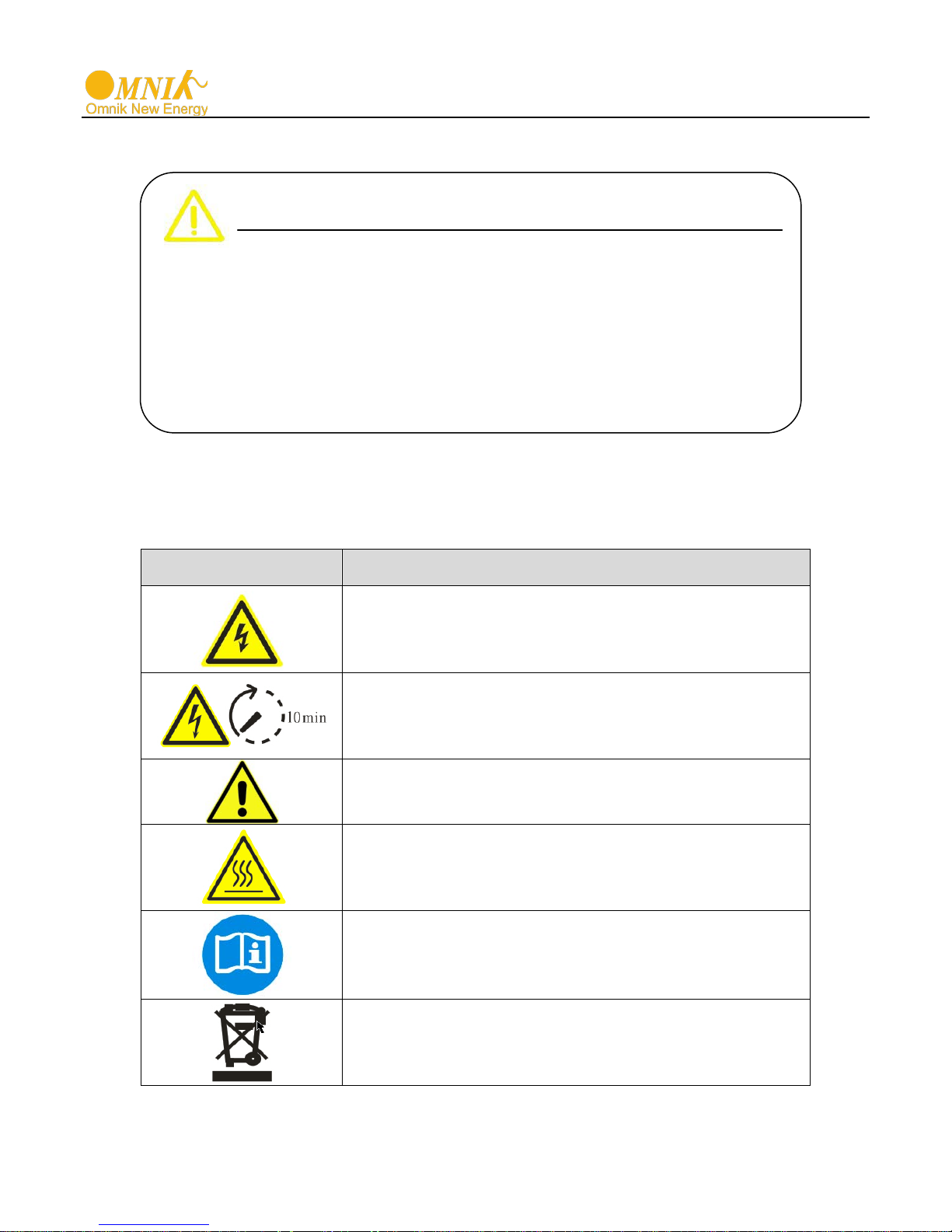
Symbol
Description
Dangerous electrical voltage
work to the inverter shall only be carried out by
qualified personnel.
DANGER to life due to high electrical voltage!
There might be residual currents in inverter because
before you
remove the front lid.
NOTICE, danger!
This device directly connected with electricity
generators and public grid.
Danger of hot surface
housing during operating.
An error has occurred
This device SHALL NOT be disposed of in
proper treatments.
CAUTION
The PV inverter will become hot during operation; please
don’t touch the heat sink or peripheral surface during or
shortly after operation。Risk of damage due to improper
modifications. Never modify or manipulate the inverter or
other components of the system.
2.2 Explanations of Symbols on Inverter
This device is directly connected to public grid, thus all
of large capacitors. Wait 10 MINUTES
The components inside the inverter will release a log
of heat during operation, DO NOT touch aluminum
Please go to Chapter 9 “Trouble Shooting” to remedy the
error.
residential waste
Please go to Chapter 8 “Recycling and Disposal” for
6
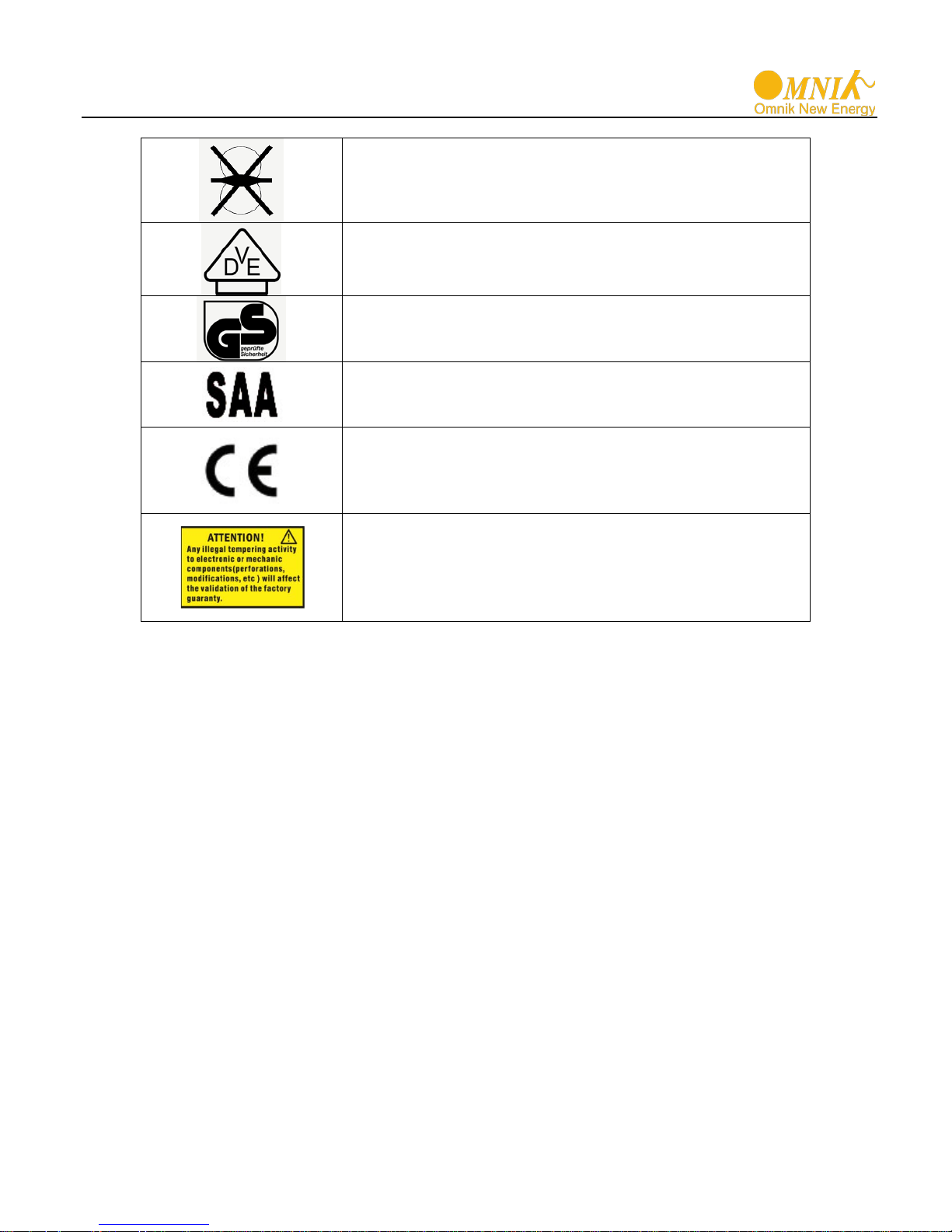
Without Transformer
German mark of conformity
Certified Safety
Equipment and Product Safety Act in Europe.
Standards Association of Australian
AS4777.
CE Mark
and Electromagnetic Compat ibi l i ty.
No unauthorized perforations or modifications
responsibility for it.
This inverter does not use transformer for the isolation
function.
The inverter complies with the requirement of the
German Grid Regulations.
The inverter complies with the requirements of the
The inverter complies with the requirement of the
Equipment with the CE mark fulfils the basic
requirements of the Guideline Governing Low-Voltage
Any unauthorized perforations or modifications are
strictly forbidden, if any defect or damage
(device/person) is occurred, Omnik shall not take any
7
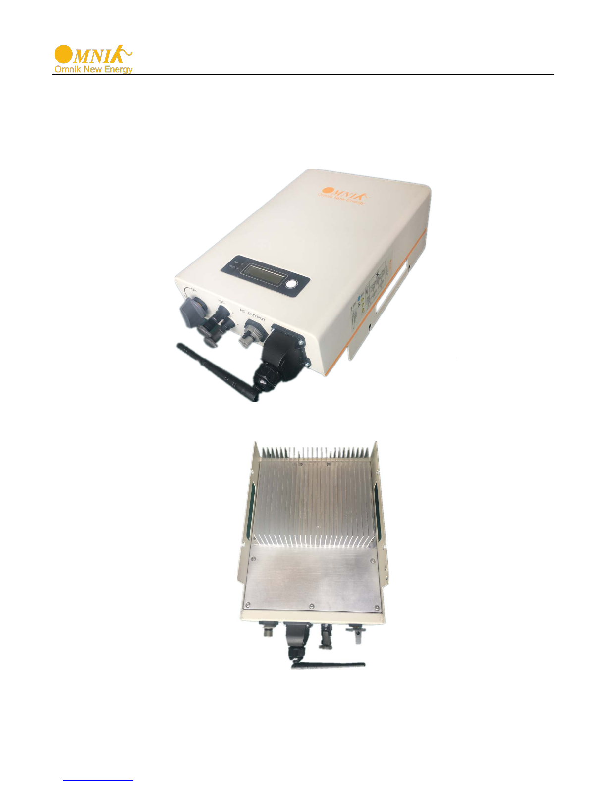
3. Product Information
3.1 Overview
• Industrial Layout
• Excellent Heat Elimination
、
8

3.2 Major Characteristics
Omnik inverter has following characteristics which make Omnik inverter “High Efficie ncy,
High Reliability, High Cost Effective Ratio”
• Wide DC input voltage and current ranges, enables more PV pan el s conn ec ted .
• Wide MPP voltage range ensure high yield under various weather conditions.
• High MPP tracking accuracy, ensure the minimum power loses during converting.
• Complete set of protection methods.
Also, following protection methods are integrated in Omnik inverter:
• Internal overvoltage
• DC insulation monitoring
• Ground fault protectio n
• Grid monitoring
• Ground fault current monitoring
• DC current monitoring
• Integrated DC switch (Optional)
9
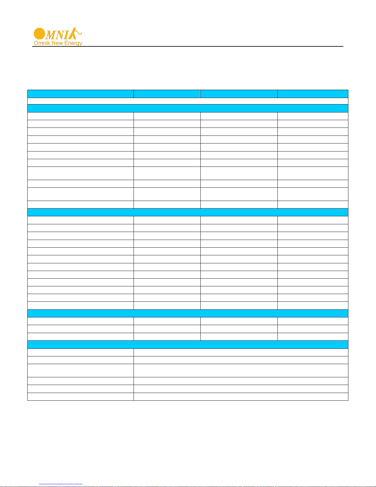
Type
Omniksol-2k-TL3-S
Omniksol-2.5k-TL3-S
Omniksol-3k-TL3-S
Input (DC)
MPPT
Number of DC Connection for each
MPPT
Output (AC)
Efficiency
Safety and Protection
(RCMU)
3.3 Datasheet
Omniksol-2k-TL3-S/ Omniksol-2.5k-TL3-S/Omniksol-3k-TL3-S
Max. PV Power 2100W 2650W 3200W
Max DC Voltage 500V 500V 500V
Operating MPPT Voltage Range 120-450V 120-450V 120-450V
MPPT Voltage Range at Nominal Power 210-450V 260-450V 320-450V
Start up DC Voltage 150V 150V 150V
Turn off DC Voltage 120V 120V 120V
Max. DC Current 10A 10A 10A
Max. Short Circuit Current for each
Number of MPP trackers 1 1 1
DC Connection Type MC4 Connector MC4 Connector MC4 Connector
Nominal AC Power(cos phi = 1) 2000W 2500W 3000W
Nominal Grid Voltage 220V/230V/240V 220V/230V/240V 220V/230V/240V
Nominal Grid Frequency 50Hz/60Hz 50Hz/60Hz 50Hz/60Hz
Max. AC Current 10.0A 12.5A 15.0A
Grid Voltage Range* 185-276V 185-276V 185-276V
Grid Frequency Range* 45-55Hz/55-65Hz 45-55Hz/55-65Hz 45-55Hz/55-65Hz
Power Factor 0.9i_1_0.9c 0.9i_1_0.9c 0.9i_1_0.9c
Total Harmonic Distortion (THD) <3% <3% <3%
Feed in Starting Power 30W 30W 30W
Night time Power Consumption <1W <1W <1W
Standby Consumption 6W 6W 6W
AC Connection Type Plug-in connector Plug-in connector Plug-in connector
14A 14A 14A
1 1 1
Max. Efficiency (at 360Vdc) 97.2% 97.2% 97.2%
Euro Efficiency (at 360Vdc) 96.6% 96.6% 96.6%
MPPT Efficiency 99.9% 99.9% 99.9%
DC Insulation Monitoring Yes
DC Switch Optional
Residual Current Monitoring Unit
Grid Monitoring with Anti-islanding Yes
Protection Class I (According to IEC 62103)
Overvoltage Category PV II / Mains III (According to IEC 62109-1)
*The AC voltage and frequency range may vary depending on specific country grid
10
Integrated
 Loading...