

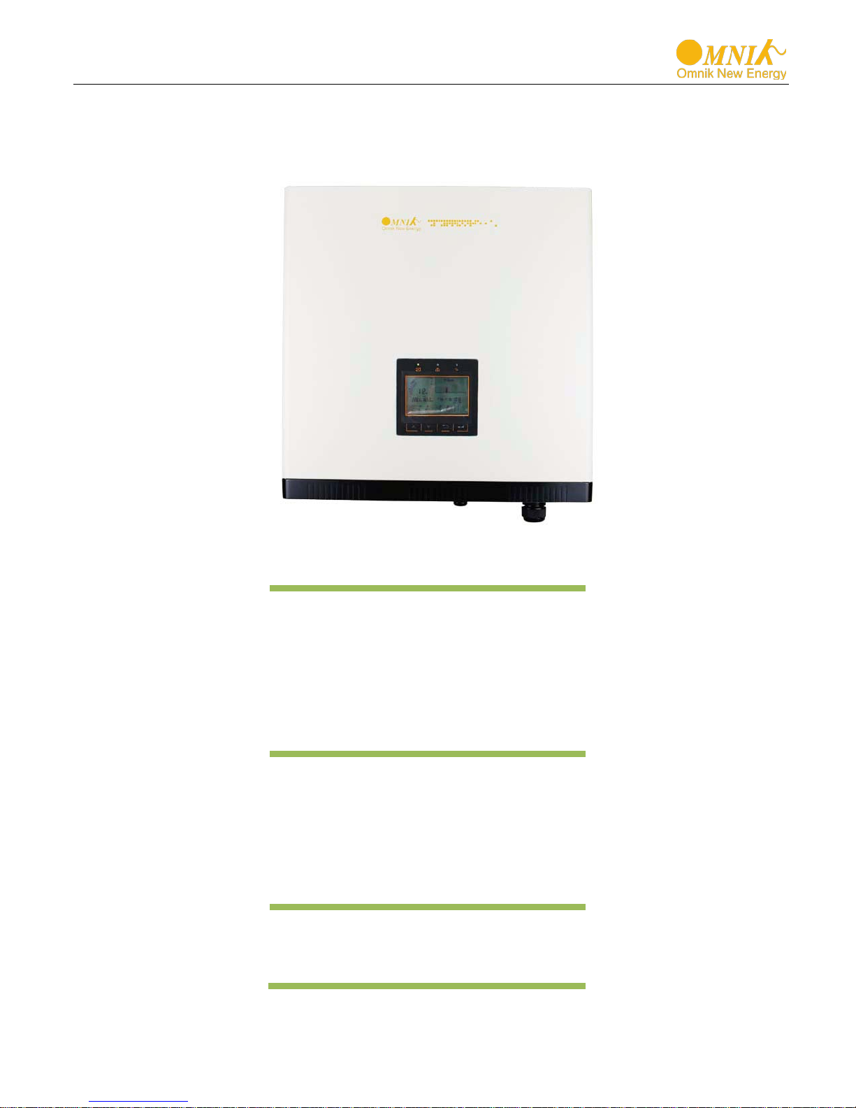
User Manual V1.2
User Manual
-Operation
Omniksol-15k-TL2
Omniksol-20k-TL2
Omnik New Energy Co.,Ltd.
-Installation
Omniksol-17k-TL2


Catalog
1. Notes on this ma nua l ............................................................................................................................... 3
1.1 General notes ..............................................................................................................................................3
Symbols Used ..............................................................................................................................................3
1.2
Target Group ...............................................................................................................................................4
1.3
2. Preparation ................................................................................................................................................ 5
2.1 Safety Instructions .......................................................................................................................................5
Explanations of Symbols on Inverter ...........................................................................................................7
2.2
3. Product Information ................................................................................................................................. 8
3.1 Overview .....................................................................................................................................................8
Major Characteristics ..................................................................................................................................9
3.2
Technical Data .......................................................................................................................................... 10
3.3
4. Packing checklist ................................................................................................................................... 12
4.1 Assembly parts ......................................................................................................................................... 12
Product Appearance ................................................................................................................................. 13
4.2
Product Identification .............................................................................................................................. 14
4.3
Further Information ................................................................................................................................. 14
4.4
5. Installation ............................................................................................................................................... 15
5.1 Safety ........................................................................................................................................................ 15
dimensions, weight .................................................................................................................................. 15
5.2
Mounting Instructions .............................................................................................................................. 16
5.3
Safety Clearance ....................................................................................................................................... 17
5.4
Mounting Procedure ................................................................................................................................ 18
5.5
6. Electrical Connection ............................................................................................................................. 19
6.1 Safety ........................................................................................................................................................ 19
DC Side Connection .................................................................................................................................. 20
6.2
AC side connection ................................................................................................................................... 23
6.3
7. Display ..................................................................................................................................................... 25
7.1 LCD Panel .................................................................................................................................................. 25
Indicator ................................................................................................................................................... 26
7.2
Button ....................................................................................................................................................... 26
7.3
1

Display ...................................................................................................................................................... 27
7.4
State Information ..................................................................................................................................... 42
7.5
8. Communication Setting ......................................................................................................................... 44
8.1 GPRS Card ................................................................................................................................................. 44
Installation of communication card ......................................................................................................... 45
8.2
Register on monitoring website ............................................................................................................... 48
8.3
Login monitoring System .......................................................................................................................... 52
8.4
WiFi card ................................................................................................................................................... 57
8.5
Netwoek Settings ..................................................................................................................................... 58
8.6
RS485 card ................................................................................................................................................ 68
8.7
9. Recycling and Disposal ......................................................................................................................... 69
10. Troubleshooting ..................................................................................................................................... 70
11. Abbreviation ............................................................................................................................................ 72
12. Contact .................................................................................................................................................... 73
2
DANGER
DANGER indicates a hazardous situation which, if not
avoided, will result in death or serious injury.
WARNING
WARNING indicates a hazardous situation which, if not
CAUTION
CAUTION indicates a hazardous condition which, if not
NOTICE
NOTICE indicates a situation that can result in property
1. Notes on th is manu al
1.1 General notes
The main purpose of this User’s Manual is to provide instructions and detailed
procedures for installing, operating, maintaining, and troubleshooting the following three
types of Omnik New Energy-Solar Inverters:
• Omniksol-15k-TL2
• Omniksol-17k-TL2
• Omniksol-20k-TL2
Please keep this user manual all time available in case of emergency.
1.2 Symbols Used
avoided, can result in death or serious injury or moderate
injury.
avoided, can result in minor or moderate injury.
damage, if not avoided.
3
WARNING
qualified personnel in accordance with the instructions in
NOTICE
Hereby qualified personnel means he/she has the valid license
Installing electrical equipment and PV power systems
Analyzing and reducing the hazards involved in
Selecting and using Personal Protective Equipment
(PPE).
1.3 Target Group
• Chapter 1, 2, 3, 4, 7, 8, 9, 10 ,11 and Chapter 12 are intended for anyone who is intended
to use Omnik Grid Tie Solar Inverter. Before any further action, the operators must first
read all safety regulations and be aware of the potential danger to operate high-voltage
devices. Operators must also have a complete understanding of this device’s features and
functions.
Do not use this product unless it has been successfully installed
by
Chapter 5, “Installation”.
• Chapter 5 and Chapter 6 are only for qualified personnel who are intended to install or
uninstall the Omnik Grid Tie Solar Inverter. Installation must be suitable to the on-site
conditions and comply with local regulations and technical rules.
from the local authority in:
•
(up to 1000 V).
• Applying all applicable installation codes.
•
performing electrical work.
•
4
DANGER
DANGER due to electrical shock and high voltage
WARNING
recycling and disposal of the
inverters must be performed by qualified personnel only in
compliance with national and local standards and
regulations. Please contact your dealer to get the
accordingly.
2. Preparation
2.1 Safety Instructions
DO NOT touch the operating component of the inverter, it
might result in burning or death.
TO prevent risk of electric shock during installation and
maintenance, please make sure that all AC and DC terminals
are plugged out.
DO NOT stay close to the instruments while there is severe
weather conditions including storm, lighting etc.
The installation,service ,
information of authorized repair facility for any maintenance
or repairmen.
Any unauthorized actions including modification of product
functionality of any form will affect the validation of warranty
service; Omnik may deny the obligation of warranty service
5
CAUTION
The PV inverter will become hot during operation; please
Public utility only
The PV inverter designed to feed AC power directly into the
public utility power grid,do not connect AC output of the
device to any private AC equipment.
don’t touch the heat sink or peripheral surface during or
shortly after operation。
Risk of damage due to improper modifications.
Never modify or manipulate the inverter or other components
of the system.
6
Dangerous electrical voltage
This device is directly connected to public grid, thus all
work to the inverter shall only be carried out by
qualified personnel.
DANGER to life due to high electrical voltage!
before you
NOTICE, danger!
This device directly connected with electricity
Danger of hot surface
An error has occurred
This device SHALL NOT be disposed of in
Without Transformer
CE Mark
No unauthorized perforations or modifications
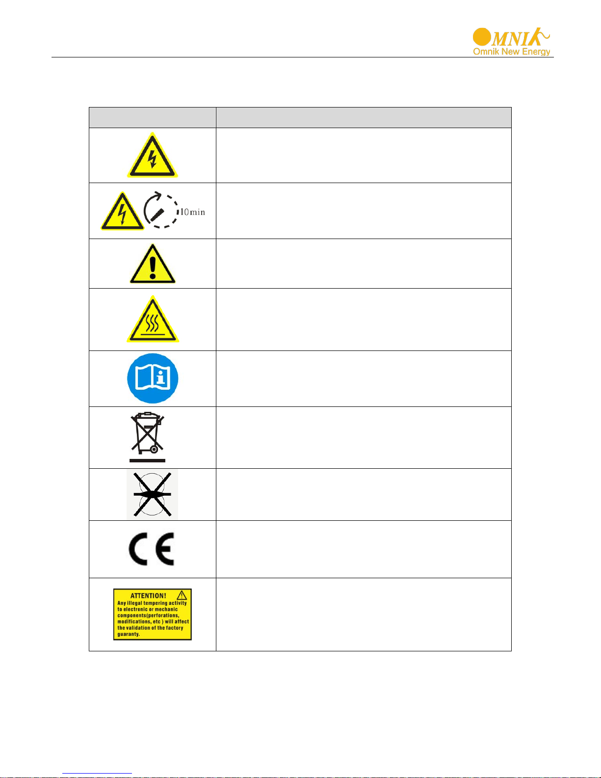
2.2 Explanations of Symbols on Invert er
Symbol Description
There might be residual currents in inverter because
of large capacitors. Wait 10 MINUTES
remove the front lid.
generators and public grid.
The components inside the inverter will release a log
of heat during operation, DO NOT touch aluminum
housing during operating.
Please go to Chapter 10 “Trouble Shooting” to remedy
the error.
residential waste
Please go to Chapter 9 “Recycling and Disposal” for
proper treatments.
This inverter does not use transformer for the isolation
function.
Equipment with the CE mark fulfils the basic
requirements of the Guideline Governing Low-Voltage
and Electromagnetic Compat ibi l i ty.
Any unauthorized perforations or modifications are
strictly forbidden, if any defect or damage
(device/person) is occurred, Omnik shall not take any
responsibility for it.
7
3. Product Information
3.1 Overview
• Industrial Layout
• Excellent Heat Elimination
• Effective Shield For DC/AC/Communication Connections
8

3.2 Major Characteristics
Omnik inverter has following characteristics which make Omnik inverter “High Efficiency,
High Reliability, High Cost Effective Ratio”
• Comply with multiple safety regulation of European, Asia Pacific and Oceania countries.
• Double MPPT Tracking, MPPT tracking accuracy up to 99.9%.
• Max. Efficiency 98.2%, European Efficiency 97.8%.
• Professional radiating design, protection Level IP65, work properly under severe
outdoor circumstances.
• Full solution of safety protection, DC switch integrated.
• Flexible input and output connections support RS485, Ethernet and USB
communication.
• Transformer less design and high power density, it is lighter and more convenient for
installation.
9
Input (DC)
Max DC Voltage
1000V
1000V
1000V
Power
Turn off DC Voltage
250V
250V
250V
Max. Short Circuit Current for each
MPPT
Max. inverter back feed current to
Output (AC)
Maximum output protection current
Night time Power Consumption
<3W
<3W
<3W
Efficiency
Safety and Protection
Array polarity reverse monitoring Output over/under voltage protection
Output over/under frequency protection
Output short circuit protection
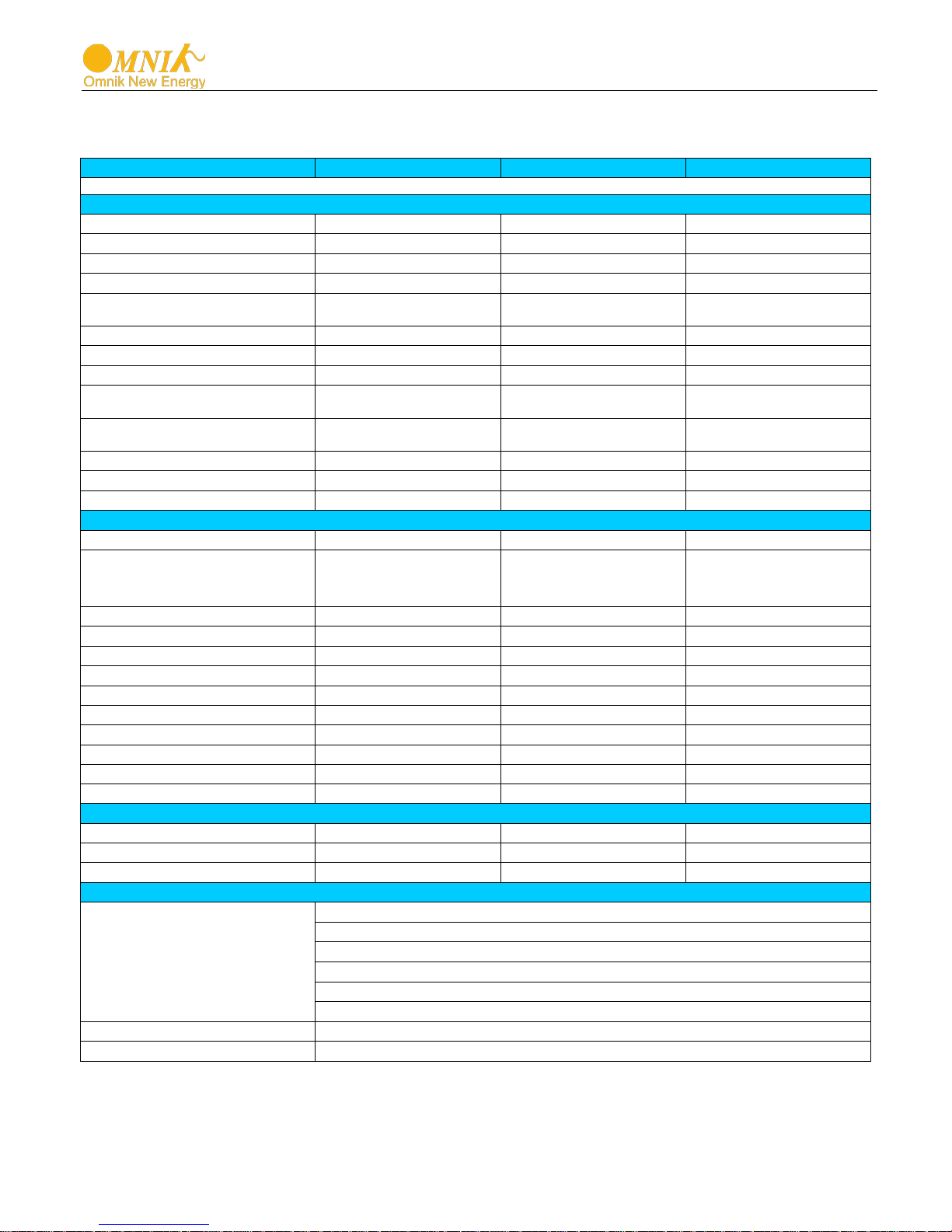
3.3 Technical Data
Type Omniksol-15k-TL2 Omniksol-17k-TL2 Omniksol-20k-TL2
Max. PV Module Power 18000W 20400W 24000W
Nominal DC Voltage 640V 640V 640V
Operating MPPT Voltage Range 250-800V 250-850V 250-850V
MPPT Voltage Range at Nominal
Start up DC Voltage 300V 300V 300V
Max. DC Current (A/B) 22A/22A 22A/22A 22A/22A
360-800V 440-850V 480-850V
25A/25A 25A/25A 25A/25A
the array [ A ]
Number of MPP trackers 2 2 2
Number of DC Connection A:3/B:3 A:3/B:3 A:3/B:3
DC Connection Type Amphenol connector Amphenol connector Amphenol connector
Nominal AC Power (cos phi = 1) 15000W 17000W 20000W
Nominal AC Voltage
Nominal Grid Frequency 50Hz/60Hz 50Hz/60Hz 50Hz/60Hz
Max. AC Current 23.0A 26.0A 29.0A
Maximum output fault current
Grid Voltage Range* 185-276V 185-276V 185-276V
Grid Frequency Range* 45-55Hz/55-65Hz 45-55Hz/55-65Hz 45-55Hz/55-65Hz
Power Factor 0.9i…1…0.9c 0.9i…1…0.9c 0.9i…1…0.9c
Total Harmonic Distortion (THD) <3% <3% <3%
AC Connection Type Terminal Blocks Terminal Blocks Terminal Blocks
Max. Efficiency 98.0% 98.0% 98.0%
Euro Efficiency 97.2% 97.2% 97.4%
MPPT Efficiency 99.9% 99.9% 99.9%
0 A / 0 A 0 A / 0 A 0 A / 0 A
3/N/PE; 220/380V
3/N/PE; 230/400V
3/N/PE; 240/415V
24.0A 27.0A 30.0A
25.0A 28.0A 31.0A
3/N/PE; 220/380V
3/N/PE; 230/400V
3/N/PE; 240/415V
3/N/PE; 220/380V
3/N/PE; 230/400V
3/N/PE; 240/415V
Array ground insulation resistance monitoring Output over current protection
Residual current monitoring Surge protection
Protection Functions
Protection Class I (According to IEC 62103)
Overvoltage Category PV II / Mains III (According to IEC 62109-1)
Array over voltage protection
Anti-island protection Over temperature protection
Array over current protection
10

Type
Omniksol-15k-TL2
Omniksol-17k-TL2
Omniksol-20k-TL2
Reference Standard
Safety Standard
EN 62109-1/-2 , IEC 62109-1/-2
EN 61000-6-1, EN 61000-6-2, EN 61000-6-3, EN 61000-6-4, E N 61000-3-11, EN
61000-3-12
IEC61683, IEC 60068, NRS 097-2-1, NB/T 32004
Physical Structure
General Data
Operating Temperature Range
Environmental Category Rating
Pollution class
EMC Standard
Grid Standard
Dimensions (WxHxD) 558x560x182mm
Weight 45kg
Environmental Protection Rating IP 65 (According to IEC 60529)
Cooling Concept Fan cooling
Mounting Information Wall bracket
Relative Humidity 0% to 100%
Max. Altitude (above sea level) 2000m
Noise Level <45dB
UV resistance
Isolation Type Transformerless
Display 5’ LCD Display
Data Communication Interfaces RS485 / WiFi / GPRS optional
Standard Warranty 5~25 years optional
*The AC voltage and frequency range may vary depending on specific country grid
VDE-AR-N-4105, VDE 0126-1-1, EN 50438, G59/3, IEC 62116, IEC 61727,
-20°C to +60°C(derating above 45℃)
Outdoor, suitable to wet locations
II
Yes
11
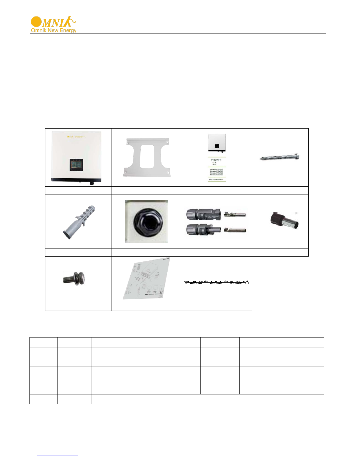
A B C
D
E F G
H
I J K
B
1
Wall mounting bracket
H
5
Cord end terminal
C
1
user manual
I
4
Screw (M4X12)
D
4
Screw(ST6x50)
J
1
Connection diagram
E
4
K
1
Removable front shield
F
1
AC cover
4. Packing checklist
4.1 Assembly parts
After you receive the Omnik inverter, please check if there is any damage on the carton,
and then check the inside completeness for any visible external damage on the inverter
or any accessories. Contact your dealer if anything is damaged or missing. we will be
glad to assist you if required.
Object Quantity Description Object Quantity Description
A 1
Omnik inverter
Expansion tube
G 6 DC connector
12

A
B
C
D
B C D
A
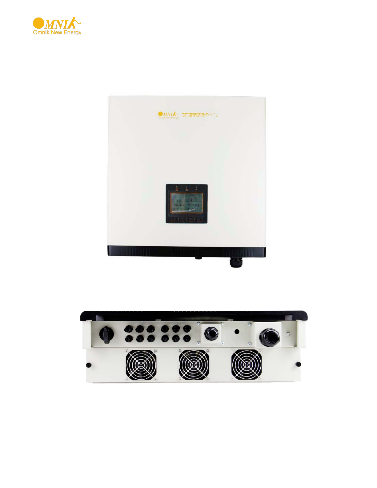
4.2 Product Appearance
• Front
Object Description
A Removable front cover
B
C
LED Light (Three)
Functional key(Four)
D LCD Display
• Bottom
Object Description
A DC switch
B Plug connectors for DC input.
C Communication interface
D Terminal for grid connection (AC output)
13
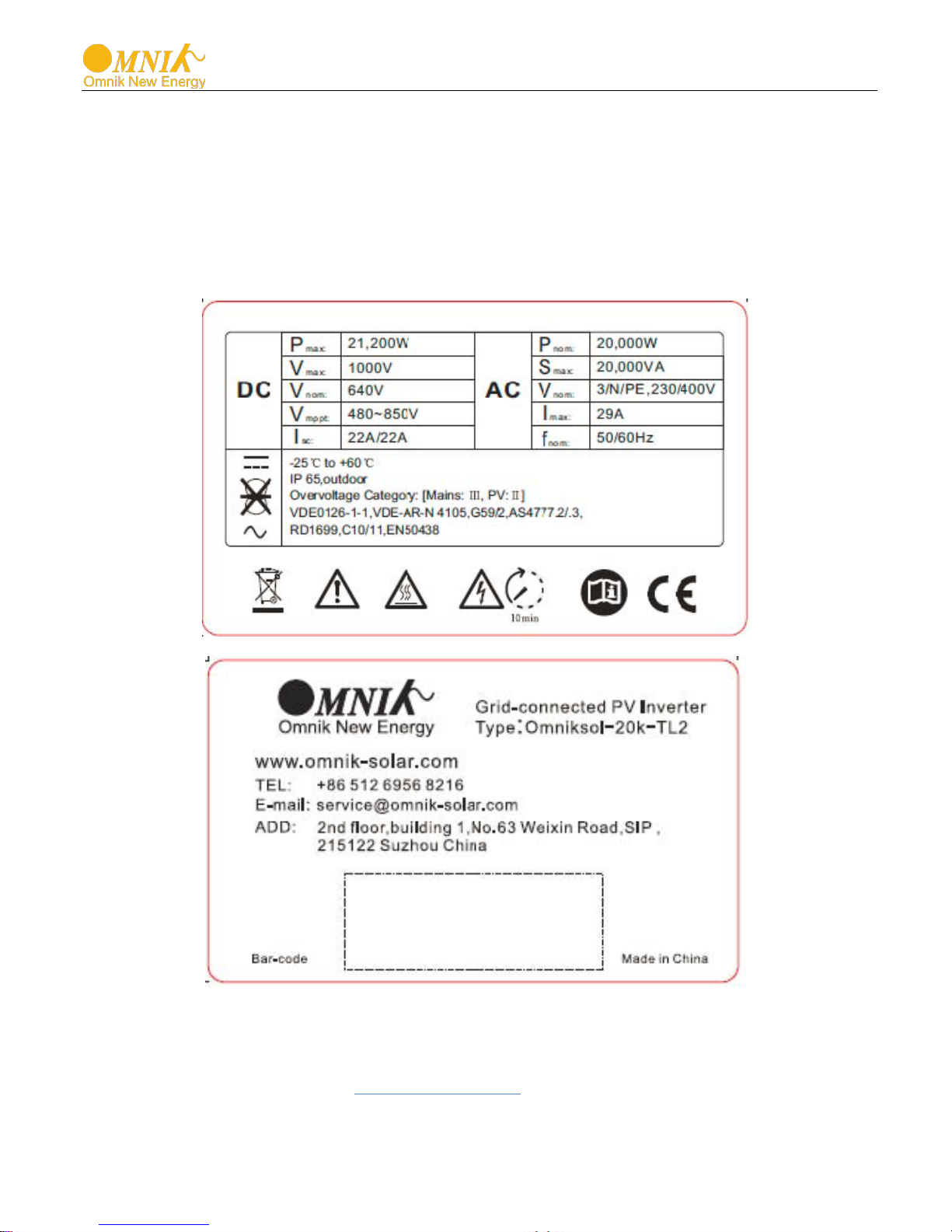
4.3 Product Identification
You can identify the inverter by the side nameplate. Information such as serial number
(SN.), type of the inverter, as well as inverter specifications are specified on the side
name plate. The name plate is on the middle part of the right side of the inverter
housing. And the following figure is the side name plate example as on Omniksol-20kTL2.
4.4 Further Inf ormation
If you have any further questions concerning the type of accessories or installation,
please check our website www.omnik-solar.com or contact our service hotline.
14
Model
weight
Dimension (L×W×D)
Omniksol-15K-TL2
45kg
Omniksol-17K-TL2
45kg
Omniksol-20K-TL2
45kg
DANGER
DANGER to life due to potential fire or electricity shock.
NOTICE
NOTICE due to the inappropriate or the harmonized
5. Installation
5.1 Safety
DO NOT install the inverter near any inflam m abl e or
explosive items.
This inverter will be directly connected with HIGH
VOLTAGE power generation device, the instal l ati on must
be performed by qualified personnel only in compliance with
national and local standards and regulations.
installation environment may jeopardize the life span
of the inverter.
Installation directly expose under intensive sunshine is not
recommended.
The installation site MUST have good ventilation condition.
5.2 dimensions, weight
558mm×560mm×182mm
558mm×560mm×182mm
558mm×560mm×182mm
15
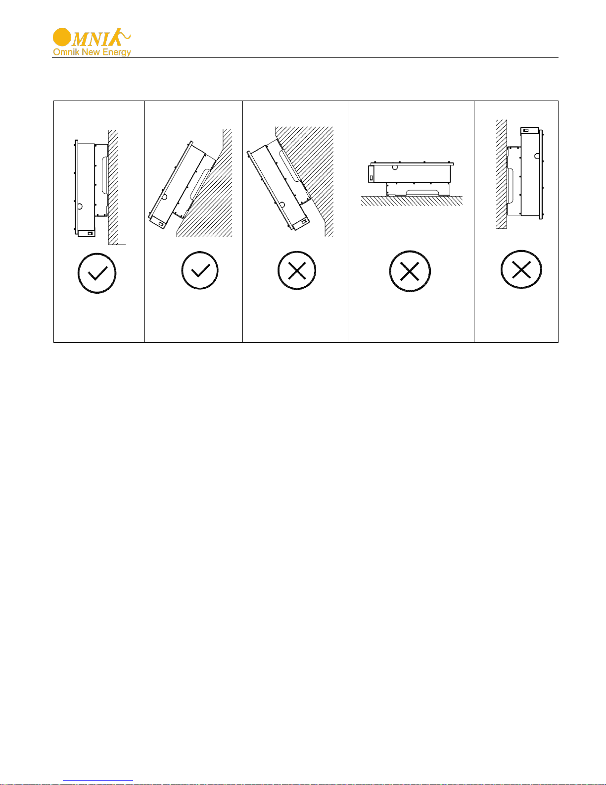
5.3 Mounting Instr uctions
• Omnik inverter is designed for indoors and outdoors installation
• Please mount the inverter in the direction as illustrated above
• Install the inverter in the vertical direction is recommended, with a max.15 degrees
backwards.
• For the convenience of checking the LCD display and possible maintenance
activities, please install the inverter at eye level.
• Make sure the wall you selected is strong enough to handle the screws and bear the
weight of the inverter
• Ensure the device is properly fixed to the wall
• It is not recommended that the inverter is exposed to the strong sunshine, because
the excess heating might lead to power reduction
• The ambient temperature of installation site should be between -25 °C and +60 °C
( between -13 °F and 140 °F )
• Make sure the ventilation of the installation spot, not sufficient ventilation may
reduce the performance of the electronic components inside the inverter and shorten
the life of the inverter
16

30cm
50cm
30cm
40cm
5.4 Safety Clearance
Observe the following minimum clearances to walls, other devices or objects to
guarantee sufficient heat dissipation and enough space for pulling the electronic solar
switch handle.
Direction Minimum clearance
Above 50 cm
Below 40 cm
Sides 30 cm
17
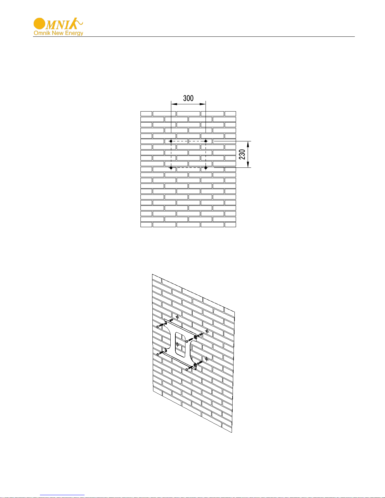
5.5 Mounting Procedure
1) Mark 4 positions of the drill holes on the wall according to the paper installation position
scale packed in the carton box.
2) First, according to the marks, drill 4 holes in the wall. Then, place four expansion tubes in
the holes using a rubber hammer. Next, wring 4 screws into the expansion tubes.
18
DANGER
DANGER to life due to potential fire or electricity shock. With
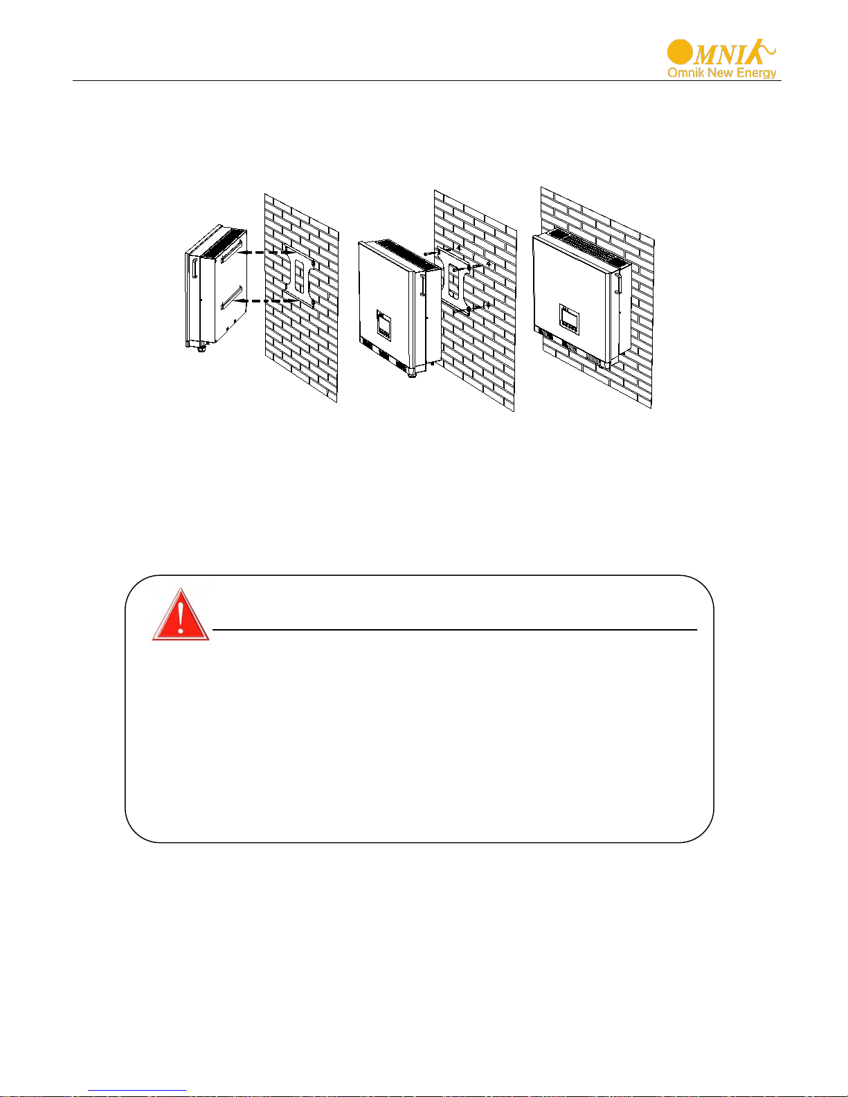
3) First check the 4 holes in the backside of the inverter. Then, lift the inverter carefully, align
the 4 holes in the inverter and the 4 scre ws in the wall, and finally attach the inverter to the
screws slightly.
4) Please carefully check the accessories and original carton to make sure every necessary
part is used and nothing is missing during installation.
6. Electri cal Con nectio n
6.1 Safety
the inverter powered, comply with all prevailing national
regulations on accidents prevention.
This inverter will be directly connected with HIGH VOLTAGE
power generation devi ce; the installation must be performed
by qualified personnel only in compliance with national and
local standards and regulations.
19
Length of cable
2.5 mm2
4 mm2
75m
120m
85m
136m
Omniksol-20k-TL2
100m
160m
DANGER
NEVER connect the ground lead of PV module to the
DANGER
DANGER to life due to potential fire or electricity shock.
NEVER connect or disconnect the connectors under load.
NOTICE
Electrical connections shall be carried out in
accordance with the applicable regulations, such as
conductor sections, fuses, PE connection.
6.2 DC Side Connection
inverter.
For Omniksol-15k-TL2, Omniksol-17k-TL2 and Omniksol-20k-TL2, there are 2 MPP
Tracker, and the DC characteristics of them are illustrated as the follow ing table.
Inverter Type
Omniksol-15k-TL2
Omniksol-17k-TL2 20400W 22/22A
Omniksol-20k-TL2 24000W 22/22A
In order to reduce the line loss of DC side (no more than 1% of Pin), Omnik suggest that
the length of DC cable for each cable section should not exceed the limit below.
Model
Omniksol-15k-TL2
Omniksol-17k-TL2
MPP
Tracker
2
Max. PV
Module Power
18000W
Max. DC
Voltage
1000V
Max. DC
Current
22/22A
20
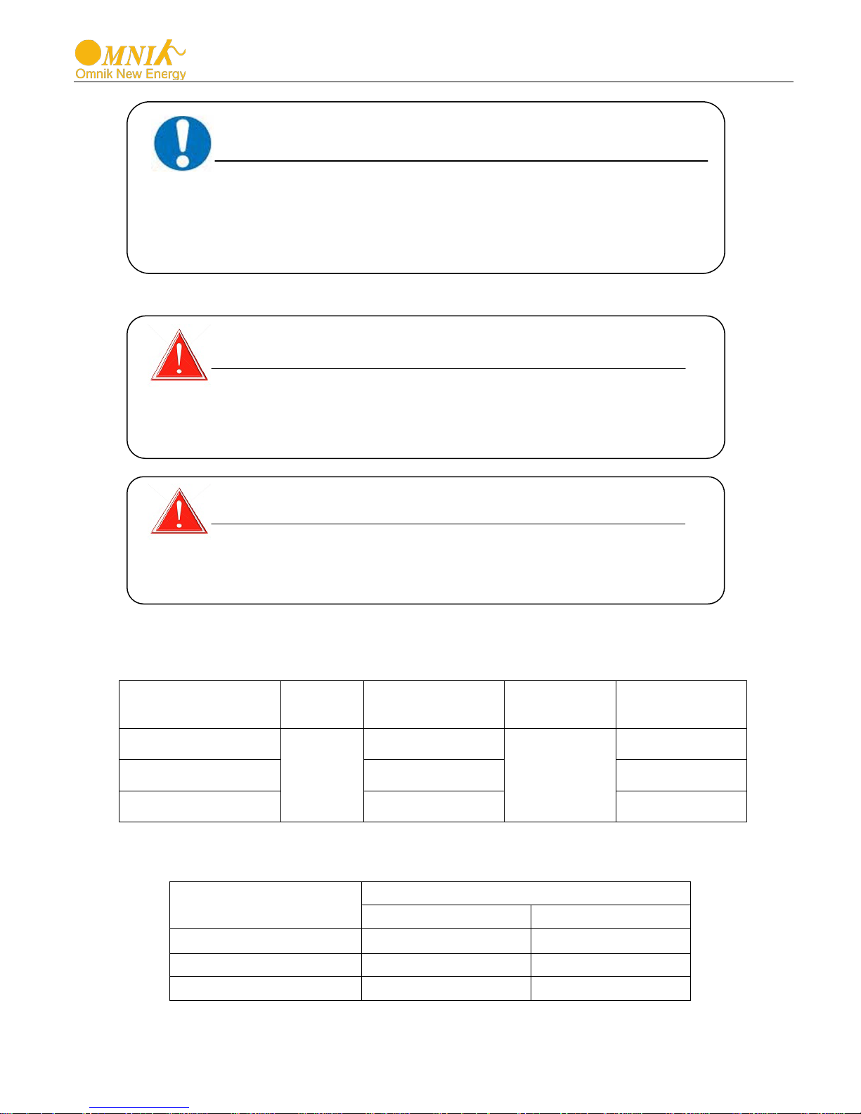
Connection procedure by MC4:
Connect the PV modules and inverter using MC4 connectors below. Connect the
positive and negative terminals from the PV modules to positive (+) terminals and
negative (-) terminals on Omniksol.
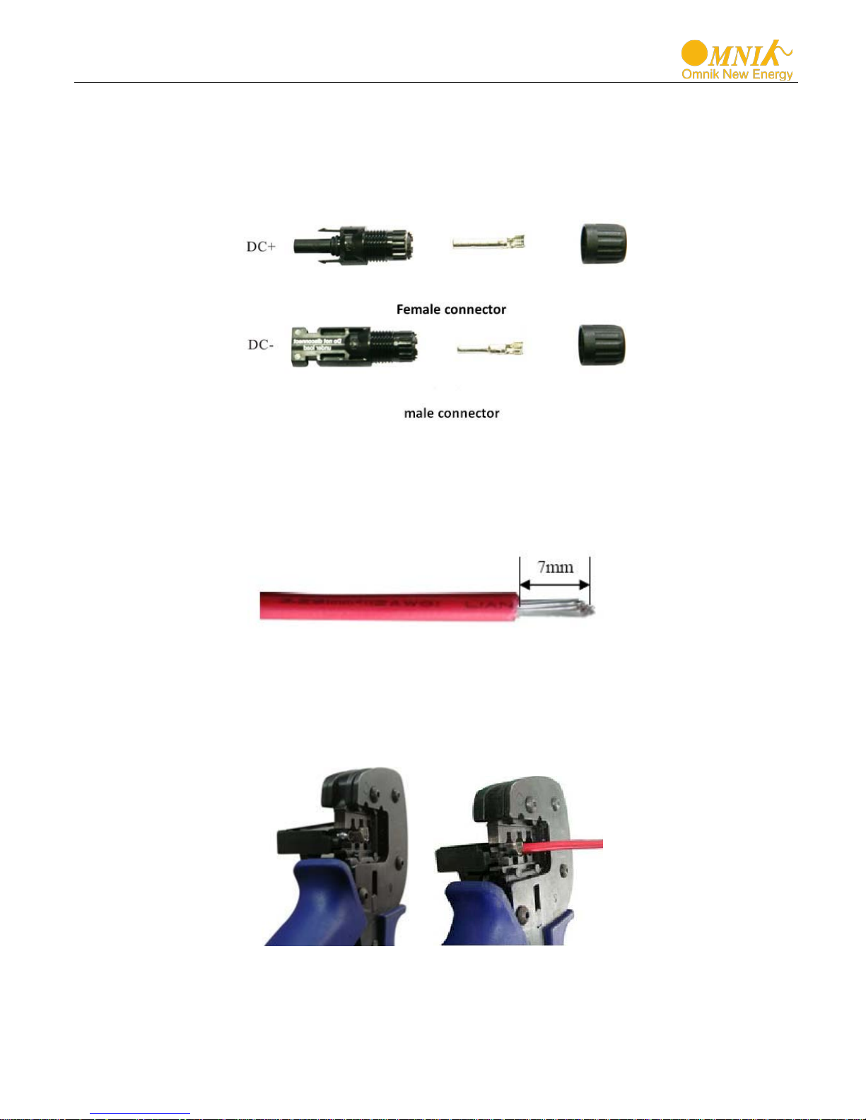
Connection Procedur e:
1) Switch off the DC breaker and secure against being switched back on inadvertently.
2) Strip the cable 7 mm.
3) Insert striped cable into contact barrel and insure all conductor strands are captured
in the contact barrel.
4) Crimp contact barrel by using a hex crimping die. Put the contact barrel with striped
cable in the corresponding crimping notch and crimp the contact.
5) Insert contact cable assembly into back of the male and female connector. A “click”
should be heard or felt when the contact cable assembly is seated correctly.
21

6) Wrest the cap by using the torque of 2.6~2.9NM.
7) After wrest the cap tightly, align the 2 half connectors and mate them together by
hand until a “click” is heared or felt.
8) When the separation of connector is necessary, use the specified wrench tool to
separate.Please make sure the wedge side of the fingers face the male connector
and push the tool down.Then separate the connector by hand. See below figure.
9) Please use sealing caps for tight sealing of unplugged PV connectors.
If using H4 connector, the operating procedure is similar as that of MC4 connector.
22

Length of cable
6 mm2
10 mm2
Omniksol-15k-TL2
21.7A
35m
59m
Omniksol-20k-TL2
29.0A
27m
44m
NOTICE
Use a residual current protective device (residual
NOTICE
Use 10-7AWG(6-10mm2) copper wire for all AC wiring
DANGER
DANGER to life due to potential fire or electricity shock.
NEVER connect or disconnect the connectors under load.
12mm
6.3 AC side connection
connections to Omnik inverter. Use only solid wire or
stranded wire.
operating current: 300mA).
In order to reduce the line loss of AC side (no more than 1% of Pout), Omnik suggest
that the len gth of AC cable from the inverter t o the distribution box should not exceed
the limit below.
Model Rated current
Omniksol-17k-TL2 24.6A 31m 52m
Connection Procedure
1) Strip the cable 12mm
23

2) Insert the striped cable into cord end terminal and insert the assembly into barrel.
3) Then the line will like the picture below.
4) Insert the finished 5 lines into AC cover assembly with the following sequence:
5) Open the plastic cover, use slot type screwdriver to press the shrapnel in the
indicated position, and then put the line in the right hole, please note the sequence
of the line shall in the right order: L1,L2,L3,N,PE
6) Cover the assembly, tightly screwed and then screw the cable gland
24

7. Display
7.1 LCD Panel
The display panel composed of three parts: lights, display and buttons. As shown in the
Figure.
25

NO.
Name
State
Description
light
Inverter connects to grid normal
dark
Inverter don’t connect to grid
light
Malfunction
dark
The machine is not the fault
flashing
Data is being transmitted
dark
No data transmission
A
B
C
A
B
C
D
7.2 Indicator
The inverter total has three indicators: running lights (green), Fault lights (red), and
Communication lights (yellow), as shown in Figure.
A Running lights
B Fault lights
C
Communication
lights
7.3 Button
The inverter total has four buttons, from the left, followed by UP button, DOWN button,
ESC button and ENTER button, as shown in figure.
Tab. Indicator Descriptio n
26

A B C D E F G
7.4 Display
Display interface is shown as Figure. Among them, red dashed box is a fixed display
area, the rest is menu display area. Menu display area is in response to key operation,
while fixed display area does not support control of keypad.
7.4.1 Fixed display area
Fixed display area is divided into seven by content, contains Instant power display block,
Models and auxiliary information display block, Generation display block, Temperature
and time display block, PV connection information display block, AC connection
information display block and Communication display block, Sequentially corresponds
to A, B, C, D, E, F and G blocks in figure above.
A:Instant power display block
Instant power display block provides two display modes, instant power values and
percentage.
B:Models and auxiliary information display block
Type information: rated power
Fans logo: indicates fan operation status
27

C:Generation display block
E-total records the total generating capacity of the inverter, E-Today records the day
generating capacity of inverter.
D:Temperature and time display block
Heat sink temperature is in the left side, the internal temperature is in the middle side
and the time is in the right side.
E:PV connection information display block
This mode provides the information of number of PV strings, PV voltage and PV current.
F:AC connection information display block
This mode provides the information of grid single / three phase, grid voltage and grid
current.
G:Communication display block
This modes provides the monitoring connection, includes RS485 communication, GPRS
communication and WiFi communication
7.4.2 Menu display area
Menu display area is divided to two display modes: menu mode and curve mode,
through the "UP" button and "DOWN" key to switch, the following sections will explain
these two modes.
1. work state interface
This interface provides current work status, current national safety regulation and grid
frequency information of current inverter, as shown in figure.
28

State
Description
wait
Initialization, waiting for the grid
run
Inverter has been connected to grid, and
is running normally
fault
Inverter malfunctions
upgrade
inverter is upgrading process
There are three main menus: Info、 Error 、Set. Each main menu consists of several
sub-menu items. Select the main menu item by "UP" button and "DOWN" button and
then enter a sub-menu item through “ENTER” button.
1) Info interface
The info interface displays serial number of inverter、type of inverter、information of
communication module and version of inverter.
a) Serial Number
29

b) Type of inverter
c) Information of communication module
30

d) Versi on o f inv er ter
2) Error interface
The error interface displays fault information, as shown in figure.
31

a
Language
i
Reset DC Coef *
q
Auto Test-F
b
Safety*
j
Time
r
AC Coef *
c
WiFi
k
Password*
s
DC Coef *
d
Energy
l
Volt Limit*
t
P(F)&Q(V)*
e
Fault
m
Freq Limit *
u
Start Time*
f
Set AC Coef*
n
Mppt Scan
v
10MinOverVolt*
g
Set DC Coef *
o
Protection*
h
Reset AC Coef *
p
Auto Test
3) Set interface
Setting menu is consist of twenty-two sub-items, as shown in the form,
Passwords is needed while setting those items with “ * ” .
a) Set Language
The inverter supports three languages, Chinese, English and Deutsch. Select the
language through “ UP” and “DOWN” button and press "ENTER" key, as shown in
figure.
32

b) Set Safety
Input the passwords first. Select the safety through “ UP” and “DOWN” button and press
"ENTER" key, as shown in figure.
c) WiFi reset
WiFi reset is to reset the WiFi AP address, as shown in figure。 Select “YES” through
“UP” and “DOWN” button and press “ENTER” button.
33

d) Clear generating capacity
Clear generating capacity means clear total generating capacity(E-Total) and clear day
generating capacity(E-Today). Select "Yes" through the "UP" and "DOWN" button and
press "ENTER" button.
e) Clear fault information
Select "Yes" through the "UP" and "DOWN" button and press "ENTER" button.
34

f) Set AC Coef
No need to set this item.
g) Set DC Coef
No need to set this item.
h) Reset AC Coef
No need to set this item.
i) Reset DC Coef
No need to set this item.
j) Set date and time
Press "UP" and "DOWN" button to adjust the "day", then press "ENTER" to adjust
"month" Similarly. So do “year”, ”hour”, ”minute” and “second”. Finally press the
"ENTER" key to finish the setting.
35

k) Set password
Input the passwords first. Press "UP" and "DOWN" button to adjust the first number.
Then press "ENTER" to adjust second number. After setting the sixth number, press the
"ENTER" key to finish the setting.
l) Set voltage limit
Input the passwords first. Press "UP" and "DOWN" button t o adjus t the first value. Then
press "ENTER" to adjust second value. After setting all the values, press the "ENTER"
key to finish the setting.
36

m) Set frequency limit
Input the passwords first. Press "UP" and "DOWN" button to adjust the first value. Then
press "ENTER" to adjust second value. After setting all the values, press the "ENTER"
key to finish the setting.
n) Mppt Scan
Press "UP" and "DOWN" button to ad just the first value. Then press "ENTER" to adjust
second value. Finally press the "ENTER" key to finish the setting.
37

o) Set protection
Input the passwords first. Press "UP" and "DOWN" button to adjust the first option. Then
press "ENTER" to adjust the second option. After setting all the options, press the
"ENTER" key to finish the setting.
p) Auto test
Only “CEI 0-21” can use this function.
38

q) Auto test-F
Only “CEI 0-21” can use this function.
.
r) AC Coef
No need to set this item.
s) DC Coef
No need to set this item.
39

t) Set P(f)&Q(v)
Input the passwords first. Press "UP" and "DOWN" button to adjust the value. Then
press "ENTER" to adjust the second value. After setting all the values, press the
"ENTER" key to finish the setting.
u) Set start time
Input the passwords first. Press "UP" and "DOWN" button to adjust the value. Then
press the "ENTER" key to finish the setting.
40

v) Set 10 minutes over voltage
Input the passwords first. Press "UP" and "DOWN" button to adjust the value. Then
press the "ENTER" key to finish the setting.
2. Curves interface
Curve interface draws day power curve, X-axis represents time in 1 hour, from the left,
the first is 1:00 to 2:00, and the far right represents the night 22:00. Y-axis represents
the power value, the full scale means rated power, as shown in figure.
41

Fac Failure: Fac Out of Range
Fac Failure :Fac Out of Range
Over Temperature in Inverter
Over Temperature in Inverter
Consistent Fault:Vac differs for M-S
Consistent Fault:Vac d i ffer s for M-S
7.5 State Information
State Display State information
Waiting Initialization & waiting
Wait
Connect Sec. Connect
Normal Normal Normal state
Fault
SPI Failure: Communication Fails
between M-S
SPI Failure: Communication Fails
between M-S
EEPROM R/W Fail EEPROM R/W Fail
Relay-Check Fail Relay-Check Fail
DC Injection High DC Injection High
The result of Auto Test Function is fail
The result of Auto Test Function is
fail
DC bus is too high DC bus is too high
The voltage reference inside is abnormal
The voltage reference inside is
abnormal
AC HCT Failure AC HCT Failure
GFCI Device Failure GFCI Device Failure
Device fault Device fault
M-S Version Unmatched M-S Version Unmatched
AC Voltage Out of Range AC Voltage Out of Range
Utility Loss Utility Loss
GFCI Failure GFCI Failure
PV Over Voltage PV Over Voltage
Isolation Fault Isolation Fault
Fan Lock Fan Lock
42

Consistent Fault:Fac differs for M-S
Consistent Fault:Fac differs for M-S
DC inj. differs for M-S
DC inj. differs for M-S
Consistent Fault:Fac, Vac Differs for M-
Consistent Fault:Fac , Vac Di ffers for
Ground I differs for M-S Ground I differs for M-S
S
M-S
High DC Bus High DC Bus
Flash Flashing Update inverter
About the further information for each fault, please reference to Chapter
“10.TROUBLESHOOTING”.
43

No.
Name
Quantity
A
PV data
1
B
GPRS
1
C
Rubber
1
No.
Name
A
14 pin connector
B
I-PEX interface
A B A B C
8. Communication Setting
8.1 GPRS Card
GPRS card is an optional device. If your inverter had installed the GPRS card, please
go to 8.3. Register on monitoring website.
After unpacking the box, please check the parts according to the below list. Contact the
manufacturer immediately when you find any damage, missing or wrong model.
collector
antenna
washer
Omnik provide 2 kinds of GPRS cards. One is a standard GPRS card and the other one
has a card slot.
Standard GPRS card
44

No.
Name
A
14 pin connector
B
SIM card slot
A C B
GPRS card with card slot
C I-PEX Interface
The serial number is shown as below.
8.2 Installati on of communication c ard
Warning: Before installing the GPRS card to inverter, you must turn off both the AC side and DC
side of inverter to make sure personal safety.
45

Unscrew the four screws on the interface panel with the screwdriver as shown in Picture above
and keep the screws aside.
The standard connector has two holes. Use the single-hole rubber washer to take place of the
double-hole rubber washer.
Insert the GPRS antenna through the gland and screw the hex nut with a torque of 2.0 N.m.
46

Connect the data line into the I-PEX interface.
While using the second kind of GP RS card, just insert the SIM card into the card slot. Then insert
the GPRS card into the inverter.
Install the communication box back to the inverter. While the installation is completed, Antenna can
be turned in 360 degrees.
47

8.3 Register on monitoring website
The PV monitoring system of Omnik is supported by: IE8, Firefox, Chrome, and Safari. Login the
website
requirements for registration; please fill in the information for register. After successful registration,
enter the mailbox and activity the account, then to complete the registration.
http://www.omnikportal.com, click register to enter the user registration page, follows the
48
Click and enter the register interface

Choose the account type
Remarks: please read the < Omnik service agreement > carefully, the enclosure is the cost list
for all the countries; please choose your operators End User means the final user
“*” you must fill it
49

50
Fill in the power station information

After the register, you may enter next chapter 8.4 Login Monitoring System.
Fill in the power station information
51

Input the
Power station list
8.4 Login monitori ng System
After the successful register and account activation, open the login interface as below. Input the
correct email and code. Enter the PV monitoring system. Then you can monitor and manage the power
station.
correct email
and code
Input the email and code
52
User interface

Not yet open
Back to user
Enter the sharing
Enter the configure
Add one case under your account
Reset
List of power station
interface
case
“company account”
interface
Navigation Bar
53

Change
Case info search
Power station info
Energy saving
Real-time power and generated energy switchover
Print current figure
case
Main interface of Power Station
54

Internal temperature
Latest data collecting time
Parameter options
Choose the aim inverter
Real Time Interface
History Interface
55

Alert Interface
56
System Setting Interface

No.
Name
Quantity
PV data
WiFi
Rubber
A B C
Add serial number
8.5 WiFi card
WiFi card is an optional device. If your inverter had installed the WiFi card, please go to 8.6.
Network Settings. If your inverter had not installed the WiFi card, please go to 8.2. Installation of
communication card first, then go to 8.6. Network Settings.
After unpacking the box, please check the parts according to the below list. Contact the
manufacturer immediately when you find any damage, missing or wrong model.
A
B
C
collector
antenna
washer
1
1
1
57

No.
Name
A
14 pin connector
B
Reset Button
C
I-PEX Interface
A B C
WiFi card is shown as below:
8.6 Netwoek Settings
1) Prepare a computer or device, e.g. tablet PC and smart phone that enables WiFi
2) Obtain an IP address automatically
Open Wireless Network Connection Properties, double click Internet Protocol Version
4(TCP/IPv4)
Select Obtain an IP address automatically, and click OK
58

3) Open wireless network connection and click View Wireless Networks
Select wireless network of the data logging module, no passwords required as default.
The network name consists of AP and the serial number of the product. Then click
Connect.
59

Connection successful
Notice: If AP_ (serial number of product) is not available in the wireless network list, there may be
problems in the connection or setting of data logging module. Please check if the WiFi had installed ok, and
inverter has been powered on.
60

Before troubleshooting, please inquire with your inverter installer whether you are allowed to
remove the cover of the inverter to trouble shoot the module. If not allowed, please contact
customer service.
4) Set parameters of WiFi module
(a) Open a web browser, and enter 10.10.100.254(the Default IP address of WiFi card,
you may set domain name access, please see the picture 6-14), then fill in username:
admin and password: admin, both of which are admin as default.
Recommended browsers: Internet Explorer 8+, Google Chrome 15+, Firefox 10+
Note:
①
If the IP address shows 0.0.0.0 (factory value) on your LCD (Picture5-4-1), it is not a correct
address. There are 2 c ases show 0.0.0.0:
Not connect router r i ghtly, you ne ed r eset to connect you router to make it right
Card loose in the inv er t er, please check your inverter, see chapt er 4: .WiFi Card Installation
②
The default username & password :admin, adm in, we sug ges t modify the username & passwor d:
Step: choose Account, input your username &password.
admin
admin
(b) In the configuration interface of WiFi module, you can view general information of the
module.
Follow the setup wizard to start quick setting.
61

Click Wizard to start
62
Click Start to continue

Click Refresh to search available wireless networks
63

Select the wireless network you need to connect, then click Next
Notice:
①
If the signal strength (RSSI) of the selected network is <10%, which means unstable connection,
please adjust the antenna of the router, or use a repeater to enhance the signal.
②
We recommend router setting:
Security setting: WPA2-personal
Encryption type: AES
64

Enter the password for the selected network, then click Next
Select Enable to obtain an IP address automatically, then click Next
Notice:
①
Turn off the firewall of the router
②
Make sure the DHCP function of the router is enable
65

If setting is complete, the above page will display. Click OK to restart.
If setting is complete, the above page will display.
After your WiFi card set ok and get IP address from your router for example: 192.168.16.8,
(You may see the IP addr es s fro m inverter)
66

Input: http://192.168.16.8/ will display the following page:
67

You may also add your domain name of WiFi card to easy access according below
picture , after you set ok, input http://wifi, you may also access the related page.
Now we finish the network setting, please go to 8.3. Register on monitoring website.
8.7 RS485 card
68

WARNING
This device SHALL NOT be disposed of in
residential waste.
RS485 card is an optional device. RS485 card has two RJ45 ports and one USB port. The USB
port is used to update the inverter. The RJ45 port is used to communicate with WiFi kit or GPRS kit.
WiFi/GPRS Kit
You can get more information in the user manual of WiFi/GPRS kit.
9. Recycling and Di sposal
To comply with European Directive 2012/19/EU on waste Electrical and Electronic Equipment
and its implementation as national law, electrical equipment that has reached the end of its life
must be collected separately and returned to an approved recycling facility. Any device that
you no longer required must be returned to your dealer or you must find an approved collection
and recycling facility in your area.
Ignoring this EU Directive may have severe affects on the environment and your health.
69

F00
GFCI Device Fault
Inverter GFCI Detector Issue
1.Restart to check
2.Re-Flash software
3.Replace part or inverter
F01
Island Fault
No Grid or Local Grid
Frequency Isn't Stable
Restart to check after local grid is
stable
Close the protection from the inverter
1.Correct the installation (Add Panels
More)
2.Re-Flash software
3.Replace part or inverter
F04
Consistency Fault
The Data That Be Master And
Slave CPU Detected Is
Inconsistency
1.Restart to check
2.Re-Flash software
3.Replace part or inverter
F05
Bus Volt Low
1.Test Value Wrongly
2.Software Issue
3.Hardware Broken
1.Restart to check
2.Re-Flash software
3.Replace part or inverter
F06
Bus Volt High
1.Test Value Wrongly
2.Software Issue
3.Hardware Broken
1.Restart to check
2.Re-Flash software
3.Replace part or inverter
F09
No Utility
No AC voltage
Measure AC voltage with a multi meter
Check the wires in AC cable
F10
Ground Current Fault
1.Poor grounding
2.It Often occurs in the rainy
day.
.Make inverter grounded well
2.Change it to another standard with
wider
protection range under authorization
F11
Bus Unbalance
1.Inverter Control Circuit
Problem
2.Values Of Two Rows Bus
Capacitance Differ Too Much
1.Restart to check
2.Re-Flash software
3.Replace part or inverter
F12
10min Over Volt
Mean Value Within 10min Is
Above 10% Of The Rated Grid
Voltage
Change it to another standard with
wider
protection range under authorization
F13
Over Temp Fault
The temperature of internal
device exceeds 80 ℃
It happens rarely and can be used
Normally
10. Troubleshooting
Fault
No.
F03 PV Volt Low DC voltage is below 150V
Fault Info On
Display
Possible Reasons Solutions
70

F15
PV Volt High
DC Voltage Is Too High Due To
Wrong Installation
1.Correct The Installation (Remove
Panels)
2.Re-Flash Software
3.Replace Part Or Inverter
F17
Grid Volt Fault
Grid Voltage Detection Within
A Period Is Anomalous
Change the grid voltage protection
range
F18
Isolation Fault
Impedance To Ground Between
Battery Positive and Negative
Is Less Than 2 MΩ
1.Remove this Fault
2.Change it to another standard with
wider
protection range under authorization
F19
Current DC Offset
A Phase Current Waveform
That Be Detected Is Larger
Deviation
Change it to another standard with
wider
protection range under authorization
F21
PV2 Over Current
The input current of PV2 is
over rated value. May be there
is something wrong with the
hardware
1.Restart the inverter
2.If the problem persists, please
replace the inverter.
F24
PV1 Over Current
The input current of PV1 is
over rated value. May be there
is something wrong with the
hardware
1.Restart the inverter
2.If the problem persists, please
replace the inverter.
F25
Relay Fault
General error in inverter start
time, there may be damage of
relay
If the problem persists, please
replace the inverter.
F27
Inv Over Current
The inverter current is over
rated value.
1.Restart the inverter to check
2.If it doesn't get back to normal
please replace inverter
F29
Grid Freq Fault
The grid frequency exceeds the
set range
Change it to another standard with
wider protection range under
authorization
71

Current ( Form of electricity supplied by Utility
Switch in the DC Circuit. Disconnects DC source from Inverter.
11. Abbreviation
LCD Liquid Crystal Display
LED Light Emitting Diode
MPPT Maximum Power Point Tracking
PV Photovoltaic
Vdc Voltage at the DC side
Vac Voltage at the AC side
Vmpp Voltage at the Maximum Power Point
Impp Amperage at Maximum Power Point
AC
Alternating
Company )
DC Direct Current ( Form of electricity generated by PV modules )
DC Switch
May be integrated or external to Inverter.
72

12. Contact
Omnik New Energy Co.,Ltd.(Headquarters)
Address: No.63 Weixin Road,SIP,Suzhou,China
Tel: +86-512-6956-8216
Fax: +86-512-6295-6682
E-mail: sales @omnik-solar.com
sevice@omnik-solar.com
Website: www.omniksolar.com
Omnik German branch
Address: Omnik Gmbh Forsthausstr.8A 65479 Raunheim
Tel: +49(0) 1799762654
Mobile: +49(176) 30743149
E-mail: jingjing.zhang@omnik-solar.com
Omnik UK Service Partner
Address: 3 More London Riverside SE1 2RE,London
Tel: +86 512 69568216 8833
E-mail:
OmnikItaly Srl
Address: Via Francesco Baracca, 500043 Ciampino(Roma)
Tel: +39 06 211.26. 522
Fax: +39 06 565.616.46
E-mail:
Website:
Omnik Netherlands Office
Address: Goudstraat 65,2718RD Zoetermeer, The Netherlands
Tel: +31 30265 7845
E-mail: lena.wang@omnik-solar.com
Frank.Liu@omnik-solar.com
info@omniksolar.it
www.omniksolar.it
73

74

GUARANTEE CARD
Agency retention
------------------------------------------------------------------------------------------------------------
的 User information 得
Product Model
Product ID
Purchase Date
Customer Name
的 Historical Warranty 的
Warranty date Troubleshooting Finished date Customer Signature
Client retention
75

的 User Information 得
Product Model
Product ID
Purchase Date
Customer Name
的 Historical Warranty 的
Warranty date Troubleshooting Finished date Customer Signature
--------------------------------------------------------------------------------------------------------------------------------------------------------------------------------
的 Warranty Terms 的
1. Please fill in this card carefully and read the following warranty terms carefully to
ensure that the product is effectively guaranteed.
① User keeps the card carefully when purchasing the product and asks the seller to seal
it.
② Provide the warranty card when repairing the machine in the warranty period.
③ The information in this warranty card is true; otherwise it will not be valid.
④ Warranty period is 5 years(standard) □10 years(selectable,effective after
sealing )During the warranty period, if the product fails, the quality of the
original device or the production problem, the company provides free maintenance and
parts replacement.
2. The following reasons cannot be used normally in the warranty period.
① Cause damage for not following the instructions.
② All man-made or accidental product damage
③ Without the company's approved repair, modification or product seal sticker damage.
④ Aging bruising and scratches on the surface of the product.
3. After the warranty expires, the user can still get the maintenance services provided by
the company, but the corresponding expenses shall be paid.
76
 Loading...