

Omnik Omniksol-3k-TL3-S, Omniksol-3k-TL3, Omniksol-1k-TL2-M, Omniksol-1.5k-TL2-M, Omniksol-3.68k-TL3 User Manual
...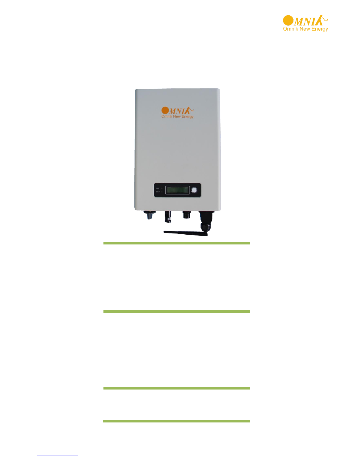
User Manual V1.1
User Manual
-Installation
-Operation
Omniksol-1k/1.5k-TL2-M
Omniksol-2k/2.5k/3k-TL3-S
Omniksol-3k/3.68k/4k-TL3
Omniksol-5k/6k-TL3
Omnik New Energy Co., Ltd.


Catalog
1. Notes on this manual .................................................................................................................... 3
1.1 Scope of Validation .................................................................................................................. 3
1.2 Symbols Used .......................................................................................................................... 3
1.3 Target Group ............................................................................................................................ 4
2. Preparation .................................................................................................................................... 5
2.1 Safety Instructions .................................................................................................................... 5
2.2 Explanations of Symbols on Inverter ........................................................................................ 6
3. Product Information...................................................................................................................... 7
3.1 Overview .................................................................................................................................. 7
3.2 Major Characteristics ................................................................................................................ 8
3.3 Datasheet ................................................................................................................................. 9
4. Packing checklist ........................................................................................................................ 17
4.1 Assembly parts ....................................................................................................................... 17
4.2 Product Appearance ............................................................................................................... 18
4.3 Product Identification .............................................................................................................. 19
4.4 Further Information ................................................................................................................. 20
5. Installation ................................................................................................................................... 21
5.1 Safety ..................................................................................................................................... 21
5.2 Mounting Instructions ............................................................................................................. 22
5.3 Safety Clearance .................................................................................................................... 23
5.4 Mounting Procedure ................................................................................................ ............... 24
5.5 Safety lock .............................................................................................................................. 27
6. Electrical Connection ................................................................................................................. 28
6.1 Safety ..................................................................................................................................... 28
6.2 AC Side Connection ................................................................................................ ............... 28
6.3 DC Side Connection ............................................................................................................... 33
7. Display ................................................................................................................................ ......... 40
7.1 LCD Panel .............................................................................................................................. 40
7.2 LCD Display ........................................................................................................................... 41
7.3 Instructions of Safety Standard selection when power-up ....................................................... 43
7.4 State Information .................................................................................................................... 44
1

8. Communication Setting .............................................................................................................. 45
8.1 GPRS Card ............................................................................................................................ 45
8.2 Installation of GPRS/WiFi card ............................................................................................... 46
8.3 Register on monitoring website .............................................................................................. 49
8.4 Login monitoring System ........................................................................................................ 52
8.5 WiFi card ................................................................................................................................ 57
8.6 Netwoek Settings ................................................................................................................... 58
8.7 Ethernet Card ......................................................................................................................... 67
8.8 Installation of Ethernet card .................................................................................................... 68
8.9 RS485 card ............................................................................................................................ 70
9. Recycling and Disposal .............................................................................................................. 75
10. Troubleshooting ......................................................................................................................... 76
11. Abbreviation ................................................................................................................................ 78
12. Contact ........................................................................................................................................ 79
2
CAUTION
CAUTION indicates a hazardous condition which, if not avoided,
can result in minor or moderate injury.
WARNING
WARNING indicates a hazardous situation which, if not
avoided, can result in death or serious injury or moderate injury.
DANGER
DANGER indicates a hazardous situation which, if not
avoided, will result in death or serious injury.
1. Notes on this manual
1.1 Scope of Validation
The main purpose of this User’s Manual is to provide instructions and detailed procedures
for installing, operating, maintaining, and troubleshooting the following four series of Omnik
Inverters:
Omniksol-1k/1.5k-TL2-M
Omniksol-2k/2.5k/3k-TL3-S
Omniksol-3k/3.68k/4k-TL3
Omniksol-5k/6k-TL3
Please keep this user manual all time available in case of emergency.
1.2 Symbols Used
3
NOTICE
Hereby qualified personnel means he/she has the valid license
from the local authority in:
• Installing electrical equipment and PV power systems
(up to 1000 V).
• Applying all applicable installation codes.
• Analyzing and reducing the hazards involved in
performing electrical work.
• Selecting and using Personal Protective Equipment
(PPE).
WARNING
Do not use this product unless it has been successfully installed
by qualified personnel in accordance with the instructions in
Chapter 5, “Installation”.
NOTICE
NOTICE indicates a situation that can result in property
damage, if not avoided.
1.3 Target Group
Chapter 1, 2, 3, 4, 7, 8, 9, 10, 11 and Chapter 12 are intended for anyone who is
intended to use Omnik Grid Tie Solar Inverter. Before any further action, the operators
must first read all safety regulations and be aware of the potential danger to operate
high-voltage devices. Operators must also have a complete understanding of this
device’s features and functions.
Chapter 5 and Chapter 6 are only for qualified personnel who are intended to install
Or uninstall the Omnik Grid Tie Solar Inverter.
4

Public utility only
The PV inverter designed to feed AC power directly into the
public utility power grid,do not connect AC output of the
device to any private AC equipment.
WARNING
The installation, service ,recycling and disposal of the
inverters must be performed by qualified personnel only in
compliance with national and local standards and
regulations. Please contact your dealer to get the
information of authorized repair facility for any maintenance
or repairmen.
Any unauthorized actions including modification of product
functionality of any form will affect the validation of warranty
service; Omnik may deny the obligation of warranty service
accordingly.
DANGER due to electrical shock and high voltage DO
NOT touch the operating component of the inverter, it might
result in burning or death. TO prevent risk of electric shock
during installation and maintenance, please make sure that
all AC and DC terminals are plugged out. DO NOT stay close
to the instruments while there is severe weather conditions
including storm, lighting etc.
2. Preparation
2.1 Safety Instructions
5

Symbol
Description
Dangerous electrical voltage
This device is directly connected to public grid, thus all
work to the inverter shall only be carried out by
qualified personnel.
DANGER to life due to high electrical voltage!
There might be residual currents in inverter because
of large capacitors. Wait 10 MINUTES before you
remove the front lid.
NOTICE, danger!
This device directly connected with electricity
generators and public grid.
Danger of hot surface
The components inside the inverter will release a log
of heat during operation, DO NOT touch aluminum
housing during operating.
An error has occurred
Please go to Chapter 10 “Trouble Shooting” to remedy the
error.
This device SHALL NOT be disposed of in
residential waste
Please go to Chapter 9 “Recycling and Disposal” for
proper treatments.
Without Transformer
This inverter does not use transformer for the isolation
function.
CAUTION
The PV inverter will become hot during operation; please
don’t touch the heat sink or peripheral surface during or
shortly after operation. Risk of damage due to improper
modifications. Never modify or manipulate the inverter or
other components of the system.
2.2 Explanations of Symbols on Inverter
6
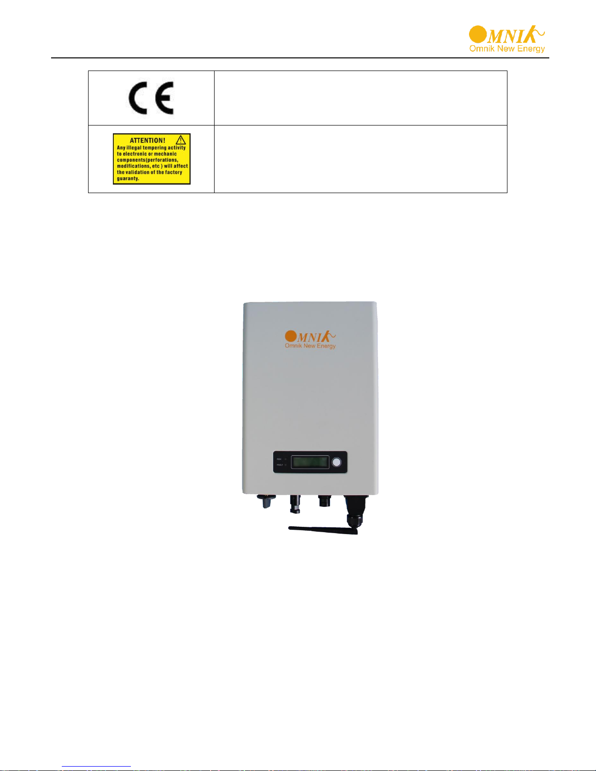
CE Mark
Equipment with the CE mark fulfils the basic
requirements of the Guideline Governing Low-Voltage
and Electromagnetic Compatibility.
No unauthorized perforations or modifications
Any unauthorized perforations or modifications are
strictly forbidden, if any defect or damage
(device/person) is occurred, Omnik shall not take any
responsibility for it.
3. Product Information
3.1 Overview
Industrial Layout (Sample)
、
7
Excellent Heat Elimination (Sample)
3.2 Major Characteristics
Omnik inverter has following characteristics which make Omnik inverter “High Efficiency,
High Reliability, High Cost Effective Ratio”
Wide DC input voltage and current ranges, enables more PV panels connected.
Wide MPP voltage range ensure high yield under various weather conditions.
High MPP tracking accuracy, ensure the minimum power loses during converting.
Complete set of protection methods.
Also, following protection methods are integrated in Omnik inverter:
Internal overvoltage
DC insulation monitoring
Ground fault protection
Grid monitoring
Ground fault current monitoring
DC current monitoring
Integrated DC switch
8

Type
Omniksol-1k-TL2-M
Omniksol-1.5k-TL2-M
Input(DC)
Max. PV Module Power [W]
1250
1750
Max. Input Power [W]
1200
1700
Max. DC Voltage [V]
500
500
Nominal DC Voltage [V]
360
360
Operating MPPT Voltage
Range [V]
60 - 400 60 - 400
MPPT Voltage Range at
Nominal Power [V]
155 - 400 155 - 400
Start up DC Voltage [V]
70
70
Turn off DC Voltage [V]
50
50
Max. DC Current[A]
10
10
Max. Short Circuit Current [A]
12
12
Number of MPP trackers 1 1
Number of DC Connection 1 1
DC Connection Type
Amphenol Connector
Amphenol Connector
Output(AC)
Max. AC Appaeent Power
[VA]
1000
1500
Nominal AC Power [W]
1000
1500
Nominal Grid Voltage [V]
220 / 230 / 240
220 / 230 / 240
Nominal Grid Frequency [Hz]
50 / 60
50 / 60
Max. AC Current [A]
5
7.5
Grid Voltage Range [V]*
185 - 276
185 - 276
Grid Frequency Range [Hz]*
45 - 55 / 55 - 65
45 - 55 / 55 - 65
Power Factor 0.9i - 0.9c
0.9i - 0.9c
Total Harmonic Distortion
(THD)
<3%
<3%
Night time Power
Consumption [W]
<1
<1
AC Connection Type
Plug-in connector
Plug-in connector
Efficiency
Max. Efficiency
96.5%
96.5%
Euro Efficiency
95.8%
96.0%
MPPT Efficiency
99.9%
99.9%
see next page
3.3 Datasheet
Datasheet of Omniksol-1k/1.5k-TL2-M
9

Safety and Protection
Protection Functions
Array ground insulation resistance monitoring Output over current protection Residual current monitoring
Array polarity reverse protection Output over/under voltage protection Surge protection
Array over voltage protection Output over/under frequency protection Anti-island protection
Array over current protection Output short circuit protection Over temperature protection
Protection Class
Ⅰ(According to IEC 62103)
Overvoltage Category
PV Ⅱ / Mains Ⅲ(According to IEC 62109-1)
Reference Standard
Safety Standard
IEC/EN 62109-1,IEC/EN 62109-2
EMC Standard
EN 61000-6-1,EN61000-6-3,EN 61000-6-2,EN61000-6-4,EN61000-3-2,EN 61000-3-3
Grid Standard
VDE-AR-N 4105,VDE 0126-1-1,C10/11,G83/2,UTE C 15-721-1,CEI 0-21,
EN50438,NB/T32004,IEC62116,IEC61727,IEC61683,IEC60068
Physical Structure
Dimensions (WxHxD) [mm]
210 * 290 * 90
Weight [kg]
5
Environmental Protection
Rating
IP 65(According to IEC 60529)
Cooling Concept
Natural convection
Mounting Information
Wall bracket
General Data
Operating Temperature
Range [℃]
-25 to +60(derating above 45℃)
Relative Humidity
0% to 100%,no condensation
Max. Altitude (above sea
level) [m]
2000
Noise Level [dB]
<40
Isolation Type
Transformerless
Display
2 LED,Backlight,2 * 16 Character LCD
Data Communication
Interfaces
RS485 / WiFi / GPRS optional
Guarantee
5 - 25 years optional
*The AC voltage and frequency range may vary depending on specific country grid
10

Type
Omniksol-2k-TL3-S
Omniksol-2.5k-TL3-S
Omniksol-3k-TL3-S
Input(DC)
Max. PV Module Power [W]
2400
3000
3600
Max. Input Power [W]
2200
2700
3300
Max. DC Voltage [V]
500
500
550
Nominal DC Voltage [V]
360
360
360
Operating MPPT Voltage
Range [V]
120 - 450
120 - 450
120 - 500
MPPT Voltage Range at
Nominal Power [V]
210 - 450
260 - 450
320 - 500
Start up DC Voltage [V]
150
150
150
Turn off DC Voltage [V]
120
120
120
Max. DC Current[A]
10
10
10
Max. Short Circuit Current [A]
14
14
14
Number of MPP trackers
1 1 1
Number of DC Connection
1 1 1
DC Connection Type
Amphenol Connector
Amphenol Connector
Amphenol Connector
Output(AC)
Max. AC Appaeent Power
[VA]
2200 2750 3300
Nominal AC Power [W]
2000
2500
3000
Nominal Grid Voltage [V]
220 / 230 / 240
220 / 230 / 240
220 / 230 / 240
Nominal Grid Frequency [Hz]
50 / 60
50 / 60
50 / 60
Max. AC Current [A]
10
12.5
15
Grid Voltage Range [V]*
185 - 276
185 - 276
185 - 276
Grid Frequency Range [Hz]*
45 - 55 / 55 - 65
45 - 55 / 55 - 65
45 - 55 / 55 - 65
Power Factor
0.9i - 0.9c
0.9i - 0.9c
0.9i - 0.9c
Total Harmonic Distortion
(THD)
<3%
<3% <3%
Night time Power
Consumption [W]
<1 <1 <1
AC Connection Type
Plug-in connector
Plug-in connector
Plug-in connector
Efficiency
Max. Efficiency
97.2%
97.2%
97.2%
Euro Efficiency
96.6%
96.6%
96.6%
MPPT Efficiency
99.9%
99.9%
99.9%
see next page
Datasheet of Omniksok-2k/2.5k/3k-TL3-S
11

Safety and Protection
Protection Functions
Array ground insulation resistance monitoring Output over current protection Residual current monitoring
Array polarity reverse protection Output over/under voltage protection Surge protection
Array over voltage protection Output over/under frequency protection Anti-island protection
Array over current protection Output short circuit protection Over temperature protection
Protection Class
Ⅰ(According to IEC 62103)
Overvoltage Category
PV Ⅱ / Mains Ⅲ(According to IEC 62109-1)
Reference Standard
Safety Standard
IEC/EN 62109-1,IEC/EN 62109-2
EMC Standard
EN 61000-6-1,EN61000-6-3,EN 61000-6-2,EN61000-6-4,EN61000-3-2,EN 61000-3-3
Grid Standard
VDE-AR-N 4105,VDE 0126-1-1,C10/11,G83/2,UTE C 15-721-1,CEI 0-21,
EN50438,NB/T32004,IEC62116,IEC61727,IEC61683,IEC60068
Physical Structure
Dimensions (WxHxD) [mm]
245 * 346 * 123
Weight [kg]
8
Environmental Protection
Rating
IP 65(According to IEC 60529)
Cooling Concept
Natural convection
Mounting Information
Wall bracket
General Data
Operating Temperature
Range [℃]
-25 to +60(derating above 45℃)
Relative Humidity
0% to 100%,no condensation
Max. Altitude (above sea
level) [m]
2000
Noise Level [dB]
<40
Isolation Type
Transformerless
Display
2 LED,Backlight,2 * 16 Character LCD
Data Communication
Interfaces
RS485 / WiFi / GPRS optional
Guarantee
5 - 25 years optional
*The AC voltage and frequency range may vary depending on specific country grid
12

Type
Omniksol-3k-TL3
Omniksol-3.68k-TL3
Omniksol-4k-TL3
Input(DC)
Max. PV Module Power [W]
3600
4400
4800
Max. Input Power [W]
1650/1650
2100/2100
2300/2300
Max. DC Voltage [V]
580
580
580
Nominal DC Voltage [V]
360
360
360
Operating MPPT Voltage
Range [V]
120 - 500
120 - 500
120 - 500
MPPT Voltage Range at
Nominal Power [V]
170 - 500
200 - 500
220 - 500
Start up DC Voltage [V]
150
150
150
Turn off DC Voltage [V]
120
120
120
Max. DC Current[A]
A:10 / B:10
A:10 / B:10
A:10 / B:10
Max. Short Circuit Current [A]
A:14 / B:14
A:14 / B:14
A:14 / B:14
Number of MPP trackers
A:1 / B:1
A:1 / B:1
A:1 / B:1
Number of DC Connection
A:1 / B:1
A:1 / B:1
A:1 / B:1
DC Connection Type
Amphenol Connector
Amphenol Connector
Amphenol Connector
Output(AC)
Max. AC Appaeent Power
[VA]
3300 3680 4400
Nominal AC Power [W]
3000
3680
4000
Nominal Grid Voltage [V]
220 / 230 / 240
220 / 230 / 240
220 / 230 / 240
Nominal Grid Frequency [Hz]
50 / 60
50 / 60
50 / 60
Max. AC Current [A]
15
16
20
Grid Voltage Range [V]*
185 - 276
185 - 276
185 - 276
Grid Frequency Range [Hz]*
45 - 55 / 55 - 65
45 - 55 / 55 - 65
45 - 55 / 55 - 65
Power Factor
0.9i - 0.9c
0.9i - 0.9c
0.9i - 0.9c
Total Harmonic Distortion
(THD)
<3%
<3% <3%
Night time Power
Consumption [W]
<1 <1 <1
AC Connection Type
Plug-in connector
Plug-in connector
Plug-in connector
Efficiency
Max. Efficiency
97.3%
97.3%
97.3%
Euro Efficiency
96.7%
96.7%
96.7%
MPPT Efficiency
99.9%
99.9%
99.9%
see next page
Datasheet of Omniksol-3k/3.68k/4k-TL3
13

Safety and Protection
Protection Functions
Array ground insulation resistance monitoring Output over current protection Residual current monitoring
Array polarity reverse protection Output over/under voltage protection Surge protection
Array over voltage protection Output over/under frequency protection Anti-island protection
Array over current protection Output short circuit protection Over temperature protection
Protection Class
Ⅰ(According to IEC 62103)
Overvoltage Category
PV Ⅱ / Mains Ⅲ(According to IEC 62109-1)
Reference Standard
Safety Standard
IEC/EN 62109-1,IEC/EN 62109-2
EMC Standard
EN 61000-6-1,EN61000-6-3,EN 61000-6-2,EN61000-6-4,EN61000-3-11,EN 61000-3-12
Grid Standard
VDE-AR-N 4105,VDE 0126-1-1,C10/11,G59/3,EN50438,NB/T32004,
IEC62116,IEC61727,IEC61683,IEC60068
Physical Structure
Dimensions (WxHxD) [mm]
288 * 380 * 130
Weight [kg]
11.5
Environmental Protection
Rating
IP 65(According to IEC 60529)
Cooling Concept
Natural convection
Mounting Information
Wall bracket
General Data
Operating Temperature Range
[℃]
-25 to +60(derating above 45℃)
Relative Humidity
0% to 100%,no condensation
Max. Altitude (above sea
level) [m]
2000
Noise Level [dB]
<40
Isolation Type
Transformerless
Display
2 LED,Backlight,2 * 16 Character LCD
Data Communication
Interfaces
RS485 / WiFi / GPRS optional
Guarantee
5 - 25 years optional
*The AC voltage and frequency range may vary depending on specific country grid
14

Type
Omniksol-5k-TL3
Omniksol-6k-TL3
Input(DC)
Max. PV Module Power [W]
6000
7200
Max. Input Power [W]
2800/2800
3300/3300
Max. DC Voltage [V]
580
580
Nominal DC Voltage [V]
360
360
Operating MPPT Voltage
Range [V]
120 - 500
120 - 500
MPPT Voltage Range at
Nominal Power [V]
270 - 500
320 - 500
Start up DC Voltage [V]
150
150
Turn off DC Voltage [V]
120
120
Max. DC Current[A]
A:10 / B:10
A:10 / B:10
Max. Short Circuit Current [A]
A:14 / B:14
A:14 / B:14
Number of MPP trackers
A:1 / B:1
A:1 / B:1
Number of DC Connection
A:1 / B:1
A:1 / B:1
DC Connection Type
Amphenol Connector
Amphenol Connector
Output(AC)
Max. AC Appaeent Power [VA]
5500
6600
Nominal AC Power [W]
5000
6000
Nominal Grid Voltage [V]
220 / 230 / 240
220 / 230 / 240
Nominal Grid Frequency [Hz]
50 / 60
50 / 60
Max. AC Current [A]
25
30
Grid Voltage Range [V]*
185 - 276
185 - 276
Grid Frequency Range [Hz]*
45 - 55 / 55 - 65
45 - 55 / 55 - 65
Power Factor 0.9i - 0.9c
0.9i - 0.9c
Total Harmonic Distortion
(THD)
<3% <3%
Night time Power Consumption
[W]
<1 <1
AC Connection Type
Terminal Blocks
Terminal Blocks
Efficiency
Max. Efficiency
98.1%
98.1%
Euro Efficiency
97.3%
97.3%
MPPT Efficiency
99.9%
99.9%
see next page
Datasheet of Omniksol- 5k&6k-TL3
15

Safety and Protection
Protection Functions
Array ground insulation resistance monitoring Output over current protection Residual current monitoring
Array polarity reverse protection Output over/under voltage protection Surge protection
Array over voltage protection Output over/under frequency protection Anti-island protection
Array over current protection Output short circuit protection Over temperature protection
Protection Class
Ⅰ(According to IEC 62103)
Overvoltage Category
PV Ⅱ / Mains Ⅲ(According to IEC 62109-1)
Reference Standard
Safety Standard
IEC/EN 62109-1,IEC/EN 62109-2
EMC Standard
EN 61000-6-1,EN61000-6-3,EN 61000-6-2,EN61000-6-4,EN61000-3-11,EN 61000-3-12
Grid Standard
G59/3,CEI 0-21,NB/T32004
Physical Structure
Dimensions (WxHxD) [mm]
343 * 425 * 136
Weight [kg]
16.8
Environmental Protection
Rating
IP 65(According to IEC 60529)
Cooling Concept
Natural convection
Mounting Information
Wall bracket
General Data
Operating Temperature Range
[℃]
-25 to +60(derating above 45℃)
Relative Humidity
0% to 100%,no condensation
Max. Altitude (above sea level)
[m]
2000
Noise Level [dB]
<40
Isolation Type
Transformerless
Display
2 LED,Backlight,2 * 16 Character LCD
Data Communication Interfaces
RS485 / WiFi / GPRS optional
Guarantee
5 - 25 years optional
*The AC voltage and frequency range may vary depending on specific country grid
16
A B C
D
E F G
H
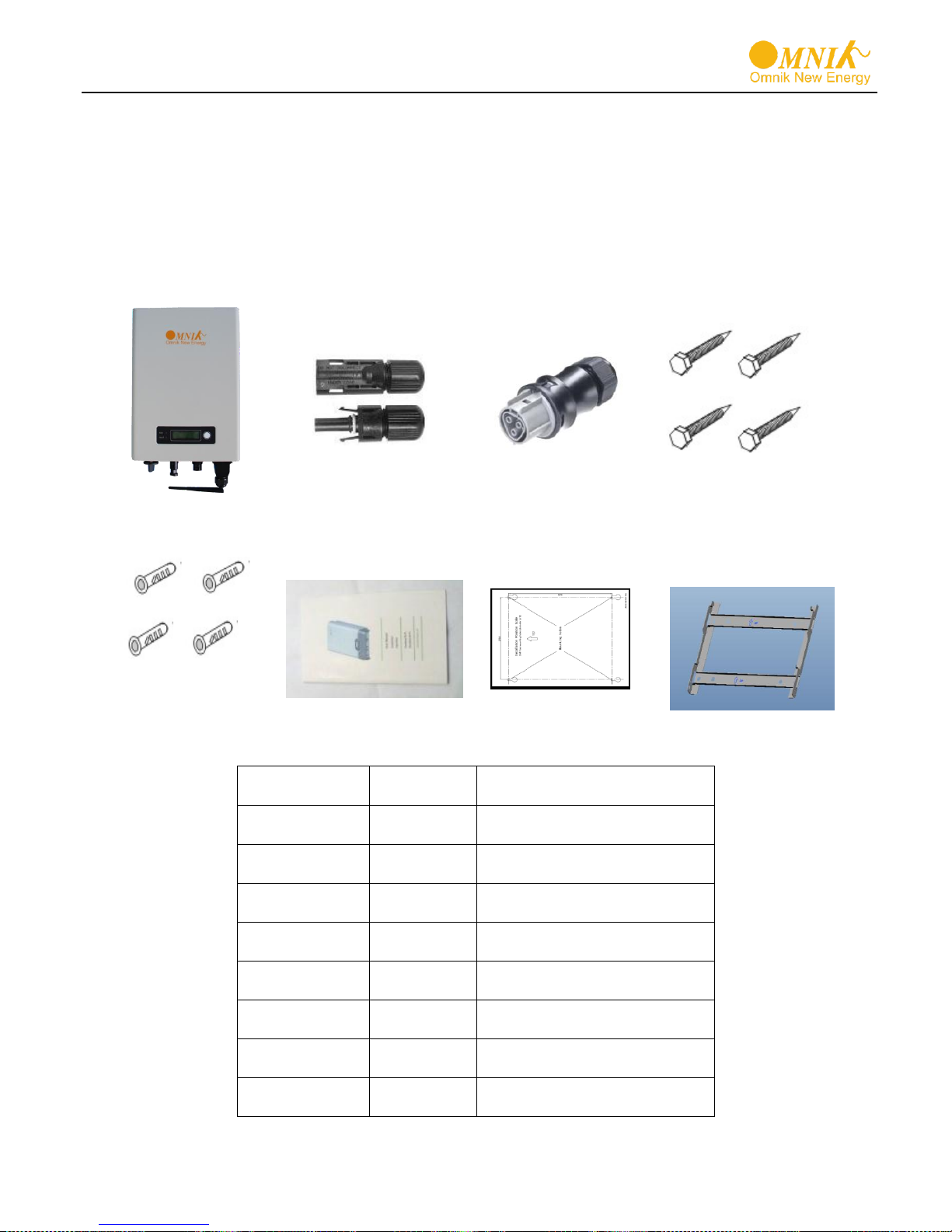
Object
Quantity
Description
A 1 Omnik inverter
B
1 pair
DC connector
C 1 AC connector
D 4 Screw (ST6×50)
E 4 Expansion tube
F 1 User manual
G
1
Installation position scale
H
1
Wall mounting bracket
4. Packing checklist
4.1 Assembly parts
After you receive the Omnik inverter, please check if there is any damage on the carton,
and then check the inside completeness for any visible external damage on the inverter or any
accessories. Contact your dealer if anything is damaged or missing.
17
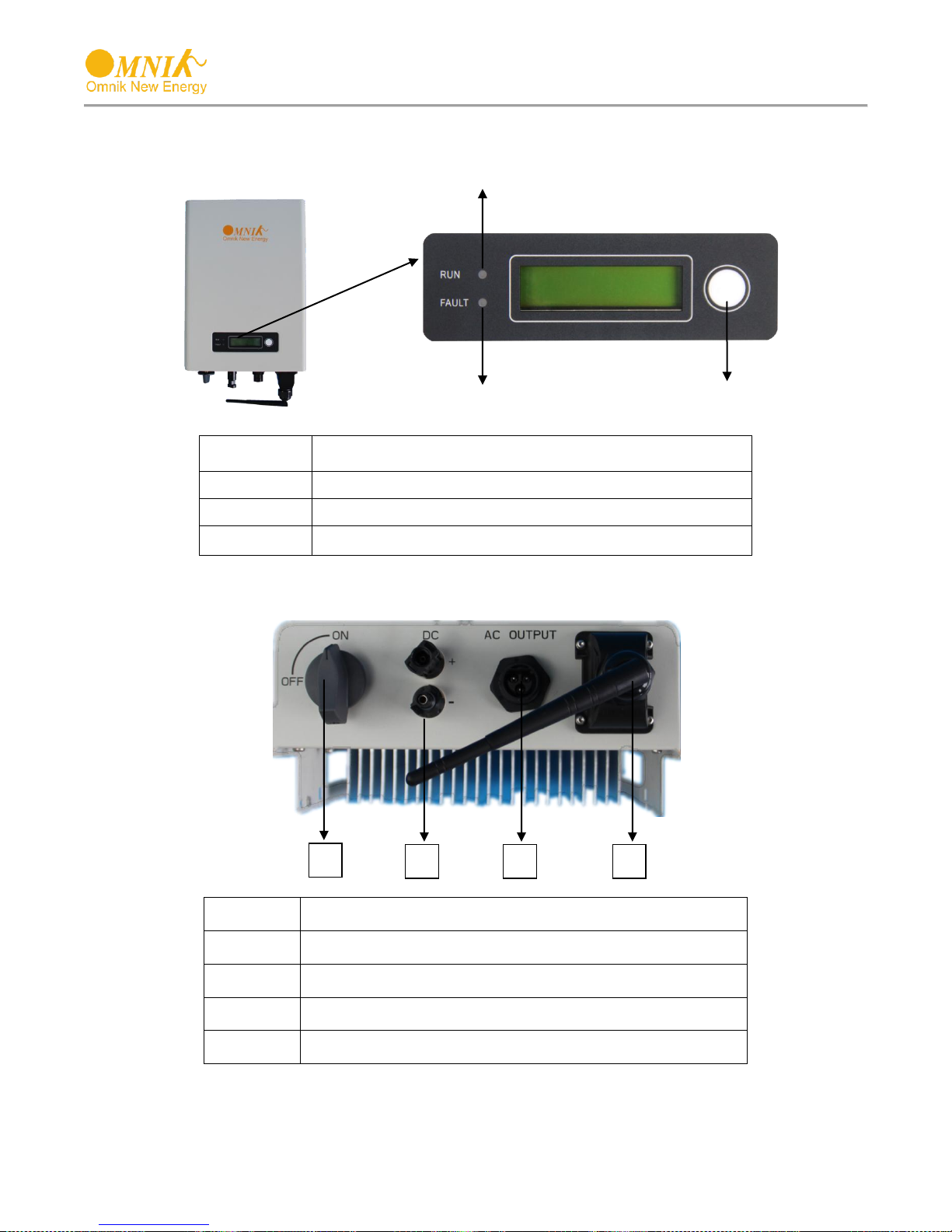
Object
Description
A
LED light(Green) – RUN
B
LED light(Red) – FAULT
C
Function key for displays and choice of language
Object
Description
A
DC switch
B
Plug connectors for DC input.
C
Terminal for grid connection (AC output)
D
WiFi/GPRS/RS485 interface
B D C
C
A
B
A
4.2 Product Appearance
Front
Bottom (style 1)
18

Object
Description
A
DC switch
B
Plug connectors for DC input.
C
WiFi/GPRS/RS485 interface
D
Terminal for grid connection (AC output)
B D C
A
Bottom (style 2)
NOTE: The order of different models of A/B/C/D modules may change. Please refer to the
actual product.
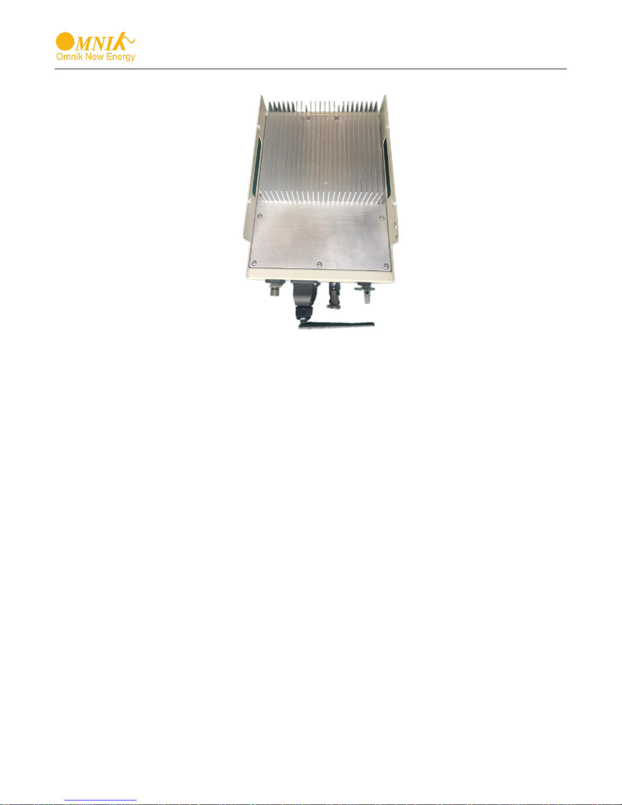
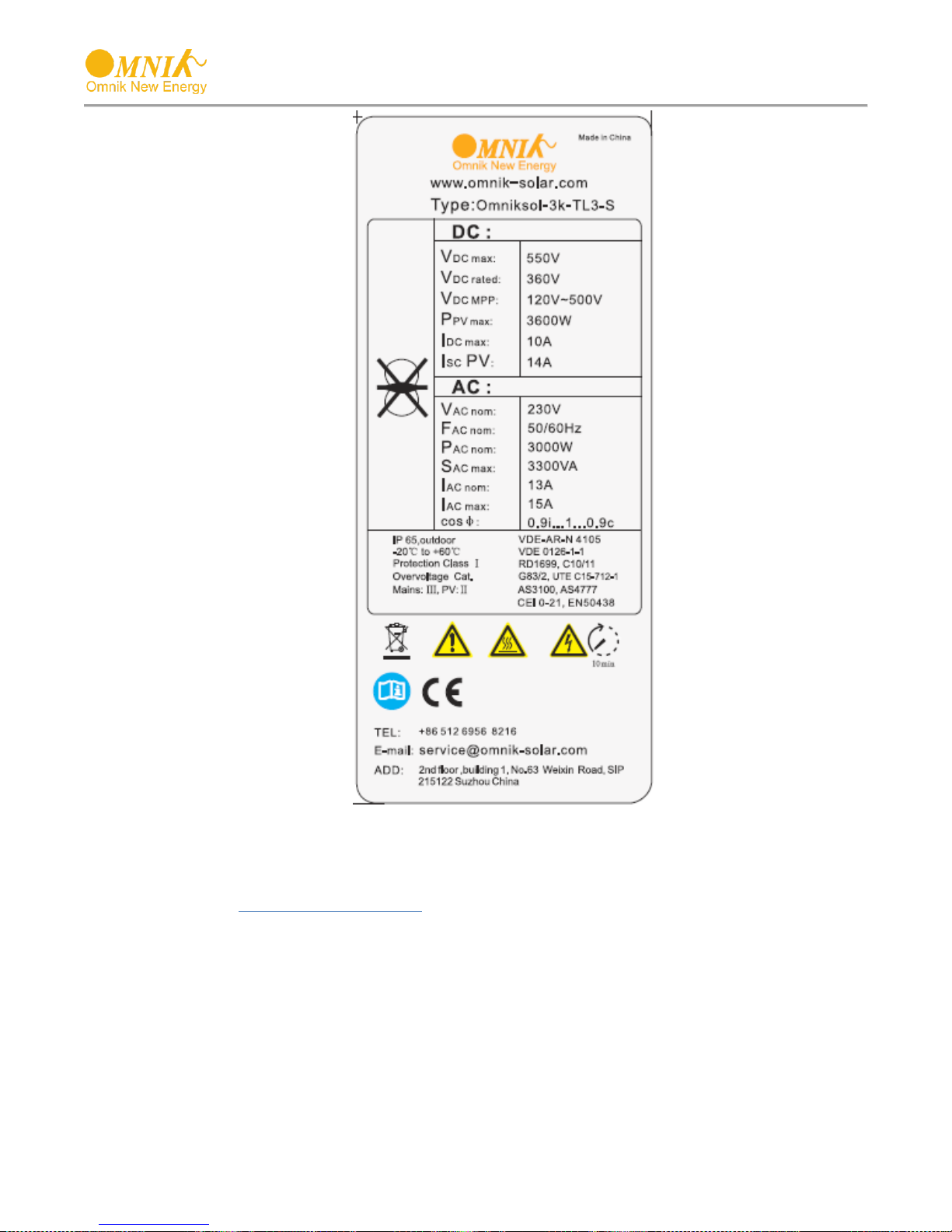
4.3 Product Identification
You can identify the inverter by the side nameplate. Information such as type of the inverter
and inverter specifications are specified on the side name plate. The name plate is on the
middle part of the right side of the inverter housing. And the following figure is the side name
plate example as on Omniksol-3k-TL3-S
19
4.4 Further Information
If you have any further questions concerning the type of accessories or installation, please
check our website www.omnik-solar.com or contact our service hotline.
20
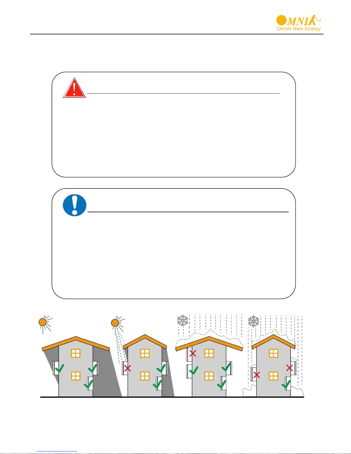
NOTICE
NOTICE due to the inappropriate or the harmonized
installation environment may jeopardize the life span
of the inverter.
Do not expose to direct sunlight to avoid power derating due
to increase in the internal temperature of the inverter.
Do not expose to rain and snow cover to enhance inverter life
time.
The installation site MUST have good ventilation condition.
DANGER
DANGER to life due to potential fire or electricity shock.
DO NOT install the inverter near any inflammable or
explosive items. This inverter will be directly connected with
HIGH VOLTAGE power generation device; the installation
must be performed by qualified personnel only in
compliance with national and local standards and
regulations.
5. Installation
5.1 Safety
21
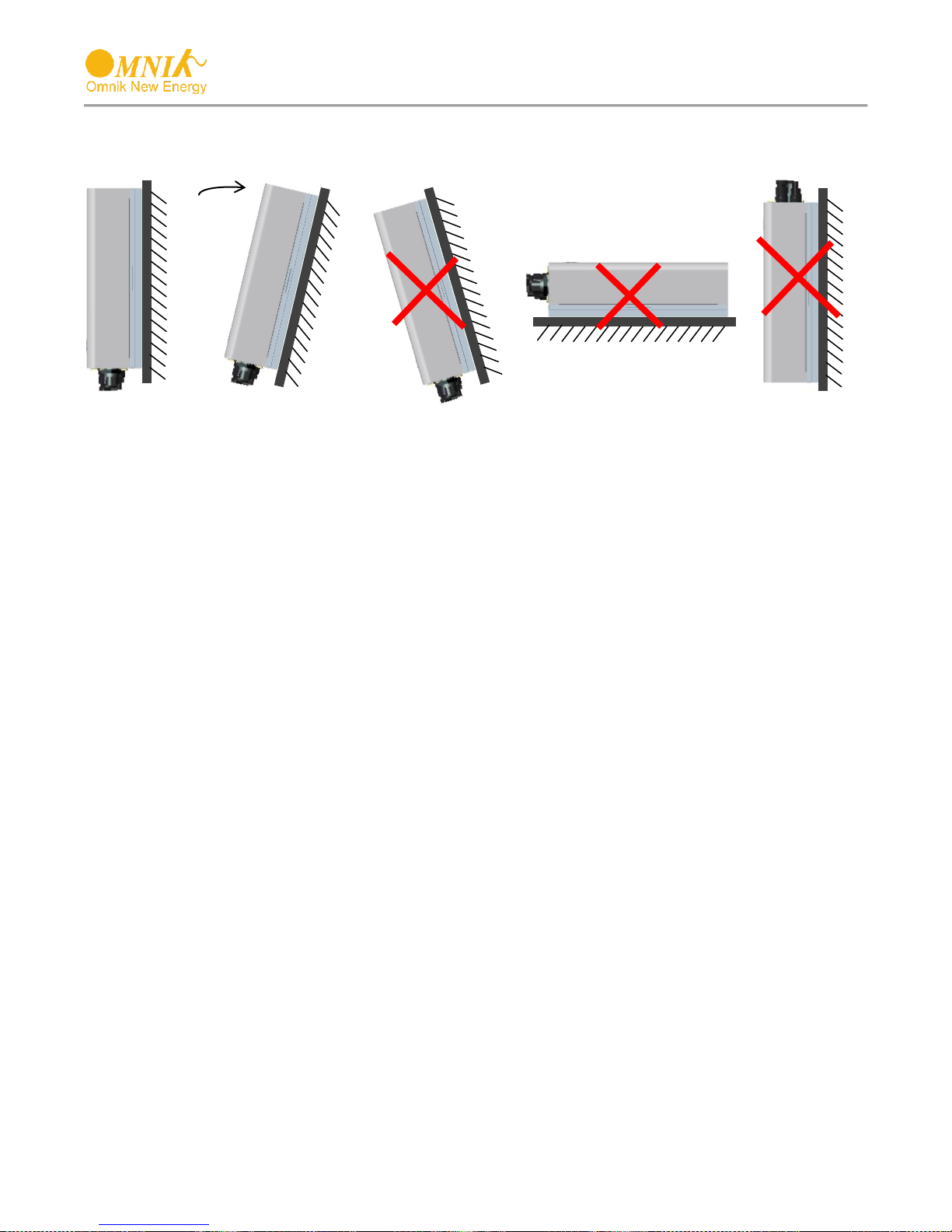
MMaaxx 1155°°
5.2 Mounting Instructions
Omnik inverter is designed for indoors and outdoors installation
Please mount the inverter in the direction as illustrated above
Install the inverter in the vertical direction is recommended, with a max.15 degrees
backwards.
For the convenience of checking the LCD display and possible maintenance activities,
please install the inverter at eye level.
Make sure the wall you selected is strong enough to handle the screws and bear the
weight of the inverter
Ensure the device is properly fixed to the wall
It is not recommended that the inverter is exposed to the strong sunshine, because the
excess heating might lead to power reduction
The ambient temperature of installation site should be between -25 °C and +60 °C
Make sure the ventilation of the installation spot, not sufficient ventilation may reduce the
performance of the electronic components inside the inverter and shorten the life of the
inverter
22
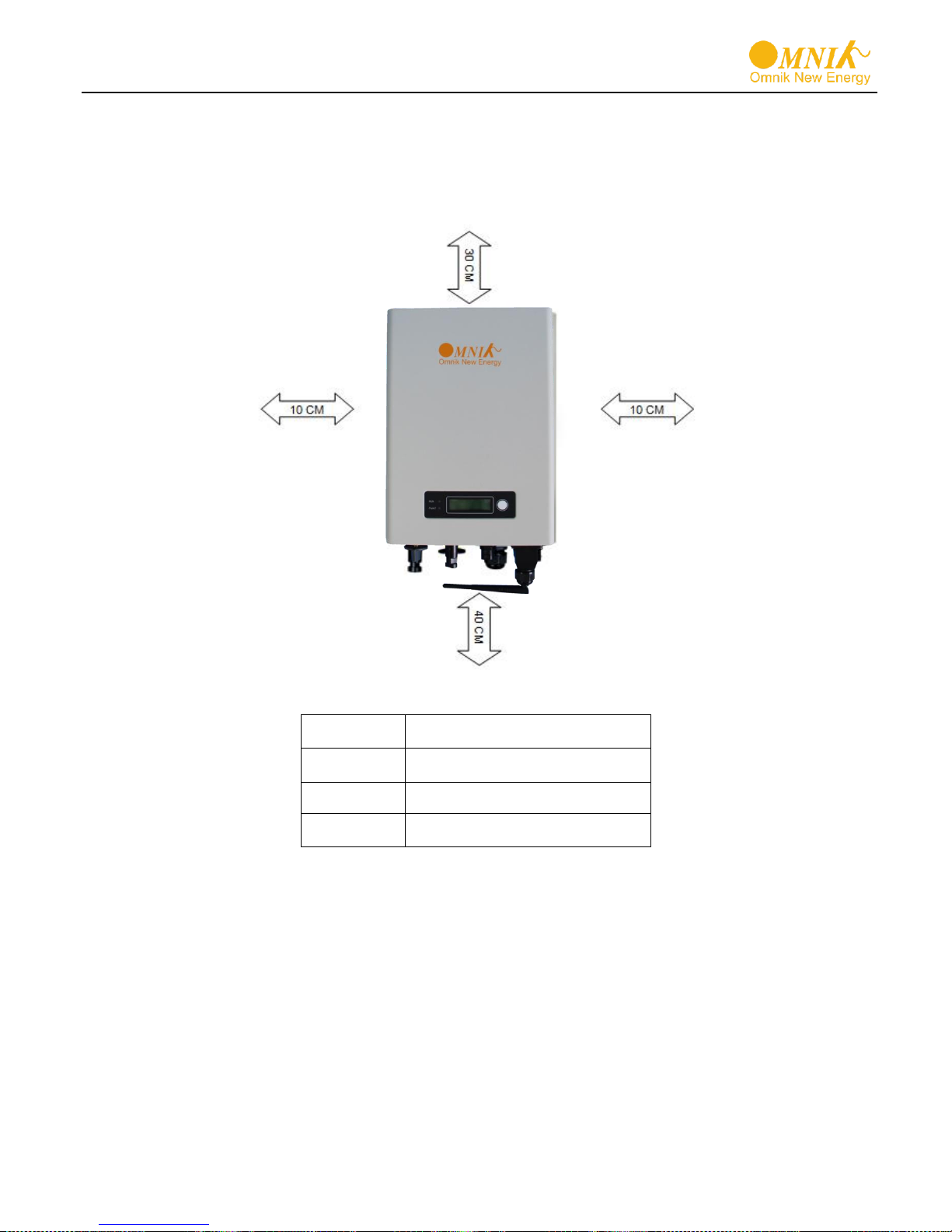
Direction
Minimum clearance
Above
30 cm
Below
40 cm
Sides
10 cm
5.3 Safety Clearance
Observe the following minimum clearances to walls, other devices or objects to guarantee
sufficient heat dissipation and enough space for pulling the electronic solar switch handle.
23

5.4 Mounting Procedure
5.4.1 Mark 2 positions of the drill holes on the wall according to the wall mounting bracket in
the carton box. (Application to model: Omniksol-1k/1.5k-TL2-M, for other models please start
from section 5.4.4 )
5.4.2 First, according to the marks, drill 2 holes in the wall. Then, place 2 expansion tubes in
the holes using a rubber hammer. Next, make 2 screws through the mounting holes in
the bracket, then tighten the screws into the expansion tubes. So far, the wall mounting
bracket is fixed already.
5.4.3 Align both sides of the radiator on the hooks of the back panel, move the inverter until
the hooks completely into the slot of the radiator.
24

Omniksol-2k/2.5k/3k-TL3-S
Omniksol-5k/6k-TL3
Omniksol-3k/3.68k/4k-TL3
5.4.4 Mark 4 positions of the drill holes on the wall according to the wall mounting bracket in
the carton box. (Application to models: Omniksol-2k/2.5k/3k-TL3-S; Omniksol3k/3.68k/4k-TL3 and Omniksol-5k/6k-TL3)
25

5.4.5 First, according to the marks, drill 4 holes in the wall. Then, place 4 expansion tubes in
the holes using a rubber hammer. Next, make 4 screws through the mounting holes in
the bracket, then tighten the screws into the expansion tubes. So far, the wall mounting
bracket is fixed already.
5.4.6 Align both sides of the radiator on the hooks of the back panel, move the inverter until
the hooks completely into the slot of the radiator.
26

A.Shackle Diameter
5~7 mm
B.Vertical Clearance
8~15 mm
C.Horizontal Clearance
12~20 mm
Stainless, solid hanger and secured lock cylinder
NOTICE
For further maintenance and possible repair, please keep the key
of the padlock in a safe place.
Padlock
C
B
A
5.5 Safety lock
After the inverter is hanging up on the bracket, lock up the device and the bracket together
at the Lower Left Corner of the inverter (as the picture showed below).
Recommended padlock dimension:
27

DANGER
DANGER to life due to potential fire or electricity shock.
NEVER connect or disconnect the connectors under load.
NOTICE
Electrical connections shall be carried out in accordance with
the applicable regulations, such as conductor sections, fuses,
PE connection.
DANGER
DANGER to life due to potential fire or electricity shock. With
the inverter powered, comply with all prevailing national
regulations on accidents prevention. This inverter will be
directly connected with HIGH VOLTAGE power generation
device; the installation must be performed by qualified
personnel only in compliance with national and local
standards and regulations.
6 Electrical Connection
6.1 Safety
6.2 AC Side Connection
6.2.1 Integrated RCD and RCM
The inverter is equipped with integrated RCD (Residual Current Protective Device) and
RCM(Residual Current Operated Monitor). The current sensor will detect the volume of the
leakage current and compare it with the pre-set value, if the leakage current exceeds the
permitted range, the RCD will disconnect the inverter from the AC load.
28

Model
Rated current
Length of cable
2.5 mm2
4 mm2
Omniksol-1k-TL2-M
4.3A
37m
59m
Omniksol-1.5k-TL2-M
6.5A
25m
40m
Model
Rated current
Length of cable
4 mm2
6 mm2
Omniksol-2k-TL3-S
10A
30m
/
Omniksol-2.5k-TL3-S
12.5A
24m
/
Omniksol-3k-TL3-S
15A
20m
30m
Model
Rated current
Length of cable
4 mm2
6 mm2
Omniksol-3k-TL3
13A
20m
30m
NOTICE
Use 14-12AWG (2.5 – 4 mm2) copper wire for all AC wiring
connections to Omniksol1k/1.5k-TL2-M
use 12-10AWG (4 – 6 mm2) copper wire for all AC wiring
connections to Omniksol-2k/2.5k/3k-TL3-S
Use 12-10AWG (4 – 6 mm2) copper wire for all AC wiring
connections to Omniksol-3k/3.68k/4k-TL3
Use 10-8AWG (6 – 10mm2) copper wire for all AC wiring
connections to Omniksol-5k/6k-TL3
The above cables use only solid wire or stranded wire.
6.2.2 Assembly Instructions
In order to reduce the line loss of AC side (no more than 1% of Pout), Omnik suggest that the
length of AC cable from the inverter to the distribution box should not exceed the limit below.
(for Omniksol-5k/6k-TL3 please start from section 6.2.2.1)
29

Omniksol-3.68k-TL3
16A
16m
24m
Omniksol-4k-TL3
17.4A
15m
22m
Model
Rated current
Length of cable
6 mm2
10 mm2
Omniksol-5k-TL3
21.7A
18m
30m
Omniksol-6k-TL3
26A
15m
25m
1) Remove length y of N, L conductor 35mm (1.38’’)/PE conductor 40mm (1.57’’) sheath of AC
cable terminal, length x about 14mm (0.55’’) of the inner wrapper, then dress the conductor
terminals with ferrules or tin soldering.
2) Check that all parts of AC connector are present. Then slide hex nut onto the cable and
insert the cable end through clamp ring.
3) Insert the stripped N, L and PE conductor terminal to the appointed holes, use a cross
screwdriver to tighten it with tightening torque 1Nm.
4) Insert the connector to clamp ring with two click sound and then tighten the hex nut with
tightening torque 4Nm.
30

5) Finally push the straight plug to the AC terminal on inverter,then rotate the locker according
to the direction instructed by the marks on the locker.
6) If you need to separate the connectors, please use a screwdriver to press the lock tongue,
rotate the locker according to the direction instructed by the marks on the locker, and then
pull down the plug.
31

Model
Rated current
Length of cable
6 mm2
10 mm2
Omniksol-5k-TL3
21.7A
18m
30m
Omniksol-6k-TL3
26A
15m
25m
12mm
6.2.2.1 Omniksol-5k/6k-TL3 Assembly Instructions
In order to reduce the line loss of AC side (no more than 1% of Pout), Omnik suggest that the
length of AC cable from the inverter to the distribution box should not exceed the limit below.
1) Strip the cable 12mm
2) Insert the striped cable into cord end terminal and insert the assembly into barrel.
32
3) Then the line will like the picture below.
4) Insert the finished 3 lines into AC cover assembly with the following sequence:
5) Open the plastic cover, use slot type screwdriver to press the shrapnel in the indicated
position, and then put the line in the right hole, please note the sequence of the line shall
in the right order: N,L,PE

Inverter Type
MPP
Tracker
Max. DC
Power
Max. DC
Voltage
Max. DC
Current
Omniksol-1k-TL2-M
1
1250W
500V
10A
Omniksol-1.5k-TL2-M
1750W
500V
10A
DANGER
NEVER connect the ground lead of PV module to the
inverter.
DANGER
DANGER to life due to potential fire or electricity shock.
NEVER connect or disconnect the connectors under load.
6) Cover the assembly, tightly screwed and then screw the cable gland.
6.3 DC Side Connection
6.3.1 For Omniksol-1k/1.5k-TL2-M and Omniksol-2k/2.5k/3k-TL3-S, there is only one MPP
Tracker, and the DC characteristics of the mare illustrated as the following table.
33

Inverter Type
MPP
Tracker
Max. DC
Power
Max. DC
Voltage
Max. DC
Current
Omniksol-2k-TL3-S
1
2400W
500V
10A
Omniksol-2.5k-TL3-S
3000W
500V
10A
Omniksol-3k-TL3-S
3600W
550V
10A
Model
Length of cable
2.5 mm2
4 mm2
Omniksol-1k-TL2-M
20m
30m
Omniksol-1.5k-TL2-M
30m
48m
Model
Length of cable
2.5 mm2
4 mm2
Omniksol-2k-TL3-S
40m
64m
Omniksol-2.5k-TL3-S
50m
80m
Omniksol-3k-TL3-S
60m
96m
Inverter Type
MPP
Tracker
Max. DC
Power
Max. DC
Voltage
Max. DC
Current
Omniksol-3k-TL3
2
3600W
580V
10A /10A
Omniksol-3.68k-TL3
4400W
580V
10A /10A
Omniksol-4k-TL3
4800W
580V
10A /10A
Inverter Type
MPP
Tracker
Max. DC
Power
Max. DC
Voltage
Max. DC
Current
Omniksol-5k-TL3
2
6000W
580V
10A /10A
Omniksol-6k-TL3
7200W
580V
10A /10A
In order to reduce the line loss of DC side (no more than 1% of Pin), Omnik suggest that
the length of DC cable for each cable section should not exceed the limit below.
6.3.2 For Omniksol-3k/3.68k/4k-TL3 and Omniksol-5k/6k-TL3, there are two MPP
Trackers, and the DC characteristics of the mare illustrated as the following table.
34

Model
Length of cable
2.5 mm2
4 mm2
Omniksol-3k-TL3
30m
48m
Omniksol-3.68k-TL3
34m
54m
Omniksol-4k-TL3
40m
64m
Model
Length of cable
2.5 mm2
4 mm2
Omniksol-5k-TL3
50m
80m
Omniksol-6k-TL3
60m
96m
In order to reduce the line loss of DC side (no more than 1% of Pin), Omnik suggest that
the length of DC cable for each cable section should not exceed the limit below.
6.3.3 MC4 Assembly instructions
If, during self assembly, parts and tools other than those stated by MC are used or
if the preparation and assembly instructions described here are disregarded then neither
safety nor compliance with the technical data can be guaranteed.
For protection against electric shock, PV-connectors must be isolated from the
power supply while being assembled or disassembled.
The end product must provide protection from electric shock.
The use of PVC cables is not recommended.
Unplugging under load: PV plug connections must not be unplugged while under
load. They can be placed in a no load state by switching off the DC/AC converter or
breaking the DC circuit interrupter. Plugging and unplugging while under voltage is
permitted.
It is unadvisable to use non-tinned cables of type H07RN-F, since with oxidized
copper wires the contact resistances of the crimp connection may exceed the permitted
limits.
Disconnected connectors should be protected from dirt and water with sealing
caps.
Plugged parts are watertight IP67. They can’t be used permanently under water.
Do not lay the MC-PV connectors on the roof surface.
See the MC catalogue 2 Solar line for technical data and assembled parts.
35

Touch
protection,
mated/unmated
IP67/IP2X
Rated
current
17A(1,5mm2/14AWG)
22A(2,5mm2/ 12AWG)
30A(4mm2,6mm2/ 10AWG)
Ambient
temperature
range
-40℃...90℃ (IEC/CEI)
-40℃ ...75℃(UL)
-40℃ ...70℃(UL/AWG14)
Rated
voltage
1000V (IEC/CEI)
600V (UL)
Upper limiting
temperature
105°C (IEC/CEI)
Safety class
II
(ill.1) Crimping tool incl. locator and built-in
crimping insert.
Type: PV-ES-CZM-18100
PV-ES-CZM-19100
(ill.2) Interchangeable crimping
inserts incl. hexagonal screwdriver A/F 2,5.
Type: PV-ES-CZM-18100
PV-ES-CZM-19100
(ill.3) Open-end spanner PV-MS 1 set = 2 pieces
Order No. 32.6024
(ill.4) PV-WZ-AD/GWD socket wrench insert to
tighten, Order No. 32.6006
PV-Female cable coupler PV-Male cable coupler
PV-KBT4 PV-KST4
Tools required
36

(ill.5) PV-SSE-AD4 socket wrench insert to
secure PV-SSE-AD4, Order No. 32.6026
(ill.6) Open-end spanner A/F 15 mm
(ill.7) Torque screwdriver A/F 12 mm
(ill.8) Test plug PV-PST
Order No.: 32.6028
Cable preparation
(ill.9) Important: Cables with class 2, 5 or 6
construction can be connected. It is advantageous to use tinned conductors. It is unadvisable to
use non-tinned cables of type H07RN-F, since
with oxidized copper wires the contact resistances
of the crimp connection may exceed the permitted
limits.
Check dimension b according to the following
table:
(ill.10) Strip cable insulation. L = 6-7, 5 mm. Take
care not to cut individual strands.
Recommended tool:
Stripping pliers PV-AZM, Order No.32.6027
Crimping
(ill.11) Notes to the operation of the crimping
pliers, see¬MA251-def (www.multicontact.com)
37

(ill.12) Push the crimped contact into the socket
resp. plug insulator until it engages. Pull lightly on
the lead to check that the metal part has
engaged.
Assembly control
(ill.13) Insert the test pin with the corresponding
side into the socket or plug to the end position. If
the contact is correctly assembled, the white
marking on the test pin
must be still visible.
(ill.14) Screw on the cable gland, hand-tight, with
the tools PV-MS. Or
Screw on the cable gland, with the tools PV-WZAD/GWD and PV-SSE-AD4
In any case:
The tightening torque must be adapted to the
solar cables used in each specific case. Typical
values lie in a range between 2,5 Nm to 3 Nm.
Plugging and unplugging the cable coupler
without safety lock clip PV-SSH4
Plugging
(ill.15)
Plug the coupling together until they engage.
Check correct engagement by pulling on the
coupling.
Unplugging
(ill.16)
Compress the two snap-in springs (X) by hand or
with the PV-MS tool and separate the coupling.
Plugging and unplugging the cable coupler
without safety lock clip PV-SSH4
38

Refer to cable manufactures specification for minimum bending radius.
39

Object
Description
A
LED light(Green) – RUN
B
LED light(Red) – FAULT
C
Function key for displays and choice of language
NOTICE
Omnik inverter is not an aligned measuring instrument
for current, voltage or power consumption. A slight
deviation of a few percent points is intrinsic to the
system; the results from the inverter cannot be used for
grid balance calculations. An aligned meter will be
required to make calculations for the utility company.
7 Display
7.1 LCD Panel
The LCD panel is integrated in the front lid of the inverter, so it is easy for user to check
and set the data. In addition, the user can press the function key to illuminate the LCD screen.
40

execution sequence
name
LCD example
1
Day total energy/kWh
E-Today = xx.x kWh
2
Total energy/kWh
E-Total = xxxxx kWh
3
PV Voltage/V
Vpv = xxx.x V
4
PV Current/A
Ipv = xx.x A
5
Grid voltage/V
Vac = xxx.x V
6
Grid current/A
Iac = xx.x A
7
Grid frequency/Hz
Frequency = xx.x Hz
8
Models
Omniksol-3k-TL3-S
9
Standard
Italy
10
Version
Version
11
Temperature
Temperature
12
Language
Language :English
13
S/N and IP address
SN/IP
14
Time setting
Date: 20xx-xx-xx
Time : xx:xx:xx
15
Grid setting
Set V/F Value
16
Protect setting
Protect :xx
17
Coefficient setting
Coefficient
18
Self Test(for Italy)
Self Test
19
P(f)and Q(v)
P(f)&Q(v)
20
Error Record
Error Record
7.2 LCD Display
The display content consists of 2 lines. The bottom line (Line 2) always displays the output
power (Pac = xxxx W). The top line (Line 1) shows current state information by default, and by
pressing function key it will display different operating information as the following flow chart
and table.
* Item 9 and 15 - 20 needs passwords. Contact your dealer or Omnik if you need to set them.
41

Line 1
Description
State information
Current state information: all possible content shows in the following table,
reference to 7.4 for further information
E-today
The energy generated today in kilo watt hours (kWh)
E-total
The energy generated since starting up the inverter (kWh)
Vpv
The present voltage of the solar generator
Ipv
The present current of the solar generator
Vac
The grid voltage
Iac
The present grid current
Frequency
The grid frequency
Model
The model of the inverter
Standard
Choose standard for different country, reference to 7.3 for further information
Version
Long press to check the firmware version
Temperature
Long press to check the temperature of the inverter
Language
Long press to set language
SN/IP
Long press to check S/N and IP address of the inverter
Date and Time
Long press to set date and time
Grid setting
Long press to set V/F value
Protect setting
Long press to change protect settings
Coefficient setting
Only used in factory
Self Test(for Italy)
Long press to start self-test
P(f)and Q(v)
Long press to set P(f)and Q(v) value
Error Record
Long press to check error record
Short press the page can be performed. Long press to enter the page and setup.
42

Function button
7.3 Instructions of Safety Standard selection when power-up
1. Attentions before the operation:
Only perform this operation when the accumulative generated electricity is less than 1kWh.
2. Operation steps are as following:
a) Power on the inverter with AC side connected.
b) Press the Function button until the first line of LCD displays “ Standard ” ,for example
“Italy”.
c) Hold the button for 5 seconds or more until the first line of LCD displays “Set”. Change
the standard by pressing the Function button one at a time.
d) When the LCD displays your desired Safety Standard, hold the Function button for 5
seconds or more until the first line of LCD shows ”Set OK”.
e) Cut down the AC power of the inverter and wait for 10 minutes .Then power on the
inverter with AC side connected again .The safety standard has been changed now.
43

State
Display
State information
Wait
Waiting
Initialization & waiting
Reconnects
Reconnect
Checking’s
Checking
Normal
Normal
Normal state
Fault
F00
GFCI Device Fault
F01
Island Fault
F03
PV Volt Low
F04
Consistency Fault
F05
Bus Volt Low
F06
Bus Volt High
F09
No Utility
F10
Ground Current Fault
F11
Bus Unbalance
F12
10min Over Volt
F13
Over Temp Fault
F15
PV Volt High
F17
Grid Volt Fault
F18
Isolation Fault
F19
Current DC Offset
F21
PV2 Over Current
F24
PV1 Over Current
F25
Relay Fault
F27
Inv Over Current
F29
Grid Freq Fault
Flash
F/W Updating
Update
7.4 State Information
About the further information for each fault, please reference toChapter“10.TROUBLESHOOTING”.
44

No.
Name
Quantity
A
PV data
collector
1
B
GPRS
antenna
1
C
Rubber
washer
1
No.
Name
A
14 pin connector
B
I-PEX interface
A B A B C
8 Communication Setting
8.1 GPRS Card
GPRS card is an optional device. If your inverter had installed the GPRS card, please
go to 8.3. Register on monitoring website.
After unpacking the box, please check the parts according to the below list. Contact the
manufacturer immediately when you find any damage, missing or wrong model.
Omnik provide 2 kinds of GPRS cards. One is a standard GPRS card and the other one
has a card slot.
45

No.
Name
A
14 pin connector
B
SIM card slot
C
I-PEX Interface
A C B
The serial number is shown as below.
8.2 Installation of GPRS/WiFi card
Warning: Before installing the GPRS card to inverter, you must turn off both the AC side
and DC side of inverter to make sure personal safety.
46

Unscrew the four screws on the interface panel with the screwdriver as shown in Picture
above and keep the screws aside.
The standard connector has two holes. Use the single-hole rubber washer to take place of
the double-hole rubber washer.
Insert the GPRS antenna through the gland and screw the hex nut with a torque of 2.0
N.m.
47

Connect the data line into the I-PEX interface.
While using the second kind of GPRS card, just insert the SIM card into the card slot.
Then insert the GPRS card into the inverter.
Install the communication box back to the inverter. While the installation is completed,
Antenna can be turned in 360 degrees.
48

8.3 Register on monitoring website
The PV monitoring system of Omnik is supported by: IE8, Firefox, Chrome, and Safari.
Login the website http://www.omnikportal.com, click register to enter the user registration
page, follows the requirements for registration; please fill in the information for register. After
successful registration, enter the mailbox and activity the account, then to complete the
registration.
Click and enter the register interface
Choose the account type
49

Remarks: please read the < Omnik service agreement > carefully, the enclosure is the
cost list for all the countries; please choose your operators End User means the final
user
“*” you must fill it
50
Fill in the power station information
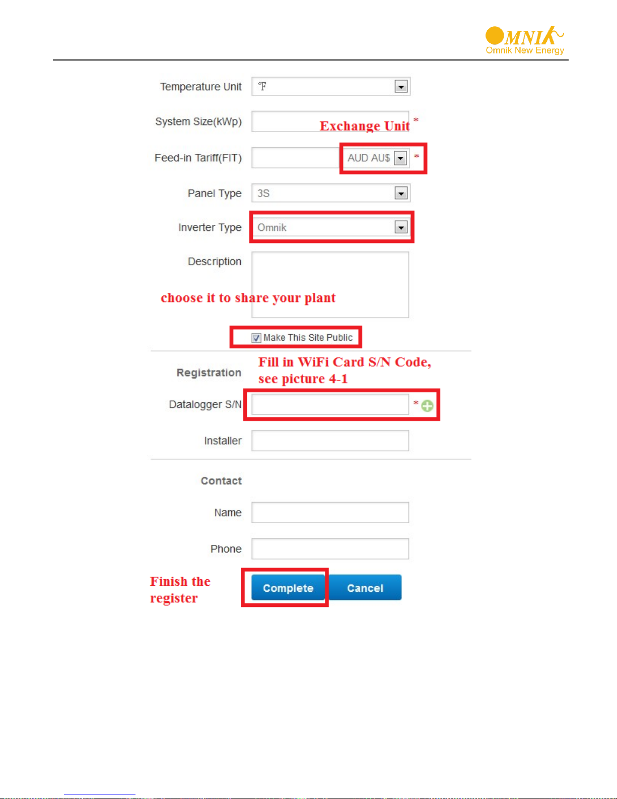
After the register, you may enter next chapter 8.4 Login Monitoring System.
Fill in the power station information
51

Input the
correct email
and code
Power station list
8.4 Login monitoring System
After the successful register and account activation, open the login interface as below.
Input the correct email and code. Enter the PV monitoring system. Then you can monitor and
manage the power station.
Input the email and code
52
User interface

Not yet open
Back to user
interface
Enter the sharing
case
Enter the configure
“company account”
interface
Add one case under your account
Reset
List of power station
Navigation Bar
53

Change
case
Case info search
Power station info
Energy saving
Real-time power and generated energy switchover
Print current figure
Main interface of Power Station
54

Internal temperature
Latest data collecting time
Parameter options
Choose the aim inverter
Real Time Interface
History Interface
55

Alert Interface
56
System Setting Interface

No.
Name
Quantity
A
PV data
collector
1
B
WiFi
antenna
1
C
Rubber
washer
1
A B C
Add serial number
8.5 WiFi card
WiFi card is an optional device. If your inverter had installed the WiFi card, please go to
8.6. Network Settings. If your inverter had not installed the WiFi card, please go to 8.2.
Installation of GPRS/WiFi card first, then go to 8.6. Network Settings.
After unpacking the box, please check the parts according to the below list. Contact the
manufacturer immediately when you find any damage, missing or wrong model.
57

No.
Name
A
14 pin connector
B
Reset Button
C
I-PEX Interface
A
B
C
WiFi card is shown as below:
Serial Number
8.6 Netwoek Settings
1) Prepare a computer or device, e.g. tablet PC and smart phone that enables WiFi
2) Obtain an IP address automatically
Open Wireless Network Connection Properties, double click Internet Protocol
Version 4(TCP/IPv4)
Select Obtain an IP address automatically, and click OK
58

3) Open wireless network connection and click View Wireless Networks
Select wireless network of the data logging module, no passwords required as default.
The network name consists of AP and the serial number of the product. Then click
Connect.
59

Connection successful
Notice: If AP_ (serial number of product) is not available in the wireless network list, there may be
problems in the connection or setting of data logging module. Please check if the WiFi had installed ok, and
inverter has been powered on.
Before troubleshooting, please inquire with your inverter installer whether you are allowed to
remove the cover of the inverter to trouble shoot the module. If not allowed, please contact
customer service.
4) Set parameters of WiFi module
(a) Open a web browser, and enter 10.10.100.254(the Default IP address of WiFi card,
you may set domain name access, please see the picture 6-14), then fill in username:
admin and password: admin, both of which are admin as default.
Recommended browsers: Internet Explorer 8+, Google Chrome 15+, Firefox 10+
Note:
①
If the IP address shows 0.0.0.0 (factory value) on your LCD (Picture5-4-1), it is not a correct address.
There are 2 cases show 0.0.0.0:
Not connect router rightly, you need reset to connect you router to make it right
Card loose in the inverter, please check your inverter, see chapter 4:.WiFi Card Installation
②
The default username & password :admin, admin, we suggest modify the username & password:
Step: choose Account, input your username &password.
60

admin
admin
(b) In the configuration interface of WiFi module, you can view general information of
the module.
Follow the setup wizard to start quick setting.
Click Wizard to start
61

Click Start to continue
Click Refresh to search available wireless networks
62

Select the wireless network you need to connect, then click Next
Notice:
①
If the signal strength (RSSI) of the selected network is <10%, which means unstable connection,
please adjust the antenna of the router, or use a repeater to enhance the signal.
②
We recommend router setting:
Security setting: WPA2-personal
Encryption type: AES
63

Enter the password for the selected network, then click Next
Select Enable to obtain an IP address automatically, then click Next
Notice:
①
Turn off the firewall of the router
②
Make sure the DHCP function of the router is enable
64

If setting is complete, the above page will display. Click OK to restart.
If setting is complete, the above page will display.
After your WiFi card set ok and get IP address from your router for example: 192.168.16.8,
(You may see the IP address from inverter)
Input: http://192.168.16.8/ will display the following page:
65

You may also add your domain name of WiFi card to easy access according below
picture , after you set ok, input http://wifi, you may also access the related page.
66

No.
Name
Quantity
A
PV data
collector
1
Now we finish the network setting, please go to 8.3. Register on monitoring website.
8.7 Ethernet Card
Ethernet card is an optional device. If your inverter had installed the Ethernet card,
please go to 8.3. Register on monitoring website. If your inverter had not installed the
WiFi card, please go to 8.8. Installation of Ethernet card first.
After unpacking the box, please check the parts according to the below list. Contact the
manufacturer immediately when you find any damage, missing or wrong model.
67

No.
Name
A
RJ45 connector
B
14 pin connector
C
Reset button
A C B
The Ethernet card is shown as below.
The serial number is shown as below.
8.8 Installation of Ethernet card
Warning: Before installing the Ethernet card to inverter, you must turn off both the AC side
and DC side of inverter to make sure personal safety.
Unscrew the four screws on the interface panel with the screwdriver as shown in Picture
above and keep the screws aside.
68

Wear the Ethernet cable into the waterproof terminals, and waterproof terminals and the
cover plate is installed.
Insert the Ethernet card into the inverter.
Connect the Ethernet cable to the Ethernet card.
69

CON 2
CON 1
CON 3
SD Card Slot
14 pin
connector
1 2 3 1 2 3 1
2
CON 1
CON 2
CON 3
Strengthen waterproof case closely back to the inverter. Then connect the other side of
the Ethernet cable to the router LAN port
8.9 RS485 card
RS485 card is used for external communication device. There are 3 connectors in the
RS485 card. The definition of the connectors is shown in the table.
70

Connector
No.
Name
Description
Connection
CON1
1
A1
RS485+ Signal
Wi-Fi/GPRS Kit
2
B1
RS485- Signal
3
GND
RS485 GND
CON2
1
A2
RS485+ Signal
CHIT DIN Meter
(DDSU 666)
2
B2
RS485- Signal
3
GND
RS485 GND
CON3
1
OP
Relay Operation
Alarm
2
NO
Relay Normal Open
RJ45
KIT
1 - 2 - 3 - 4
A1 5 B1
6 - 7
GND
8
GND
Line sequence of T568B
1. orange with white
2. orange
3. green with white
4. blue
5. blue with white
6. green
7. brown with white
8. brown
RJ45 plug
8.9.1 CON 1
CON 1 is used to communicate with Wi-Fi Kit and GPRS Kit. The connector of Kit is shown
as below.
The definition of the connector is shown in the table.
More details can be obtained in the user manual of GPRS / Wi-Fi Kit.
71

8.9.2 CON 2
CON 2 is only used to communicate with CHIT DIN Meter (DDSU 666). It can be applied
for solar projects of self-consumption without power export to the grid. It can ensure that the
power generated by solar system will not export to grid at anytime.
There are 2 types of meters. The first type of meter is connected into the power grid as
shown below.
72

No.
Meter CON
1
L(*Grid side)
2
L(Inverter side)
3 N 4 N 5 - 6 - 7
A
8
B
The definition of the connector is shown in the table.
The second type of meter is used with CT as shown below.
73

No.
Meter CON
1 L 2 L 3 N 4
N
5
CT(*White)
6
CT(*Black)
7 A 8
B
The definition of the connector is shown in the table.
More details can be obtained in the user manual of CHIT DIN Meter (DDSU 666).
CON 3
CON 3 is used to control the alarm LED. It is a pair of Normally open contacts.
The load capacity of the Relay is 230 V/0.5 A.
74

WARNING
This device SHALL NOT be disposed of in
residential waste.
9 Recycling and Disposal
To comply with European Directive 2012/19/EU on waste Electrical and Electronic
Equipment and its implementation as national law, electrical equipment that has
reached the end of its life must be collected separately and returned to an approved
recycling facility. Any device that you no longer required must be returned to your dealer
or you must find an approved collection and recycling facility in your area.
Ignoring this EU Directive may have severe affects on the environment and your health.
75

Fault No.
Fault Info On Display
Possible Reasons
Solutions
F00
GFCI Device Fault
Inverter GFCI Detector Issue
1.Restart to check
2.Re-Flash software
3.Replace part or inverter
F01
Island Fault
No Grid or Local Grid
Frequency Isn't Stable
Restart to check after local grid is stable
Close the protection from the inverter
F03
PV Volt Low
DC voltage is below 150V
1.Correct the installation (Add Panels
More)
2.Re-Flash software
3.Replace part or inverter
F04
Consistency Fault
The Data That Be Master And
Slave CPU Detected Is
Inconsistency
1.Restart to check
2.Re-Flash software
3.Replace part or inverter
F05
Bus Volt Low
1.Test Value Wrongly
2.Software Issue
3.Hardware Broken
1.Restart to check
2.Re-Flash software
3.Replace part or inverter
F06
Bus Volt High
1.Test Value Wrongly
2.Software Issue
3.Hardware Broken
1.Restart to check
2.Re-Flash software
3.Replace part or inverter
F09
No Utility
No AC voltage
Measure AC voltage with a multi meter
Check the wires in AC cable
F10
Ground Current Fault
1.Poor grounding
2.It Often occurs in the rainy
day.
.Make inverter grounded well
2.Change it to another standard with
wider
protection range under authorization
F11
Bus Unbalance
1.Inverter Control Circuit
Problem
2.Values Of Two Rows Bus
Capacitance Differ Too Much
1.Restart to check
2.Re-Flash software
3.Replace part or inverter
F12
10min Over Volt
Mean Value Within 10min Is
Above 10% Of The Rated Grid
Voltage
Change it to another standard with wider
protection range under authorization
F13
Over Temp Fault
The temperature of internal
device exceeds 80 ℃
It happens rarely and can be used
Normally
10 Troubleshooting
76

F15
PV Volt High
DC Voltage Is Too High Due To
Wrong Installation
1.Correct The Installation (Remove
Panels)
2.Re-Flash Software
3.Replace Part Or Inverter
F17
Grid Volt Fault
Grid Voltage Detection Within
A Period Is Anomalous
Change the grid voltage protection range
F18
Isolation Fault
Impedance To Ground Between
Battery Positive and Negative
Is Less Than 2 MΩ
1.Remove this Fault
2.Change it to another standard with
wider
protection range under authorization
F19
Current DC Offset
A Phase Current Waveform
That Be Detected Is Larger
Deviation
Change it to another standard with wider
protection range under authorization
F21
PV2 Over Current
The input current of PV2 is over
rated value. May be there is
something wrong with the
hardware
1.Restart the inverter
2.If the problem persists, please
replace the inverter.
F24
PV1 Over Current
The input current of PV1 is over
rated value. May be there is
something wrong with the
hardware
1.Restart the inverter
2.If the problem persists, please
replace the inverter.
F25
Relay Fault
General error in inverter start
time, there may be damage of
relay
If the problem persists, please
replace the inverter.
F27
Inv Over Current
The inverter current is over
rated value.
1.Restart the inverter to check
2.If it doesn't get back to normal
please replace inverter
F29
Grid Freq Fault
The grid frequency exceeds the
set range
Change it to another standard with
wider protection range under
authorization
77

LCD
Liquid Crystal Display
LED
Light Emitting Diode
MPPT
Maximum Power Point Tracking
PV
Photovoltaic
Vdc
Voltage at the DC side
Vac
Voltage at the AC side
Vmpp
Voltage at the Maximum Power Point
Impp
Amperage at Maximum Power Point
AC
Alternating Current ( Form of electricity supplied by Utility
Company )
DC
Direct Current ( Form of electricity generated by PV modules )
DC Switch
Switch in the DC Circuit. Disconnects DC source from Inverter.
May be integrated or external to Inverter.
11 Abbreviation
78

12 Contact
Omnik New Energy Co., Ltd. (Headquarters)
Address: Third Floor, Building 3, No.63 Weixin Road, SIP, Suzhou, China
Tel: +86-512-6956-8216
Fax: +86-512-6295-6682
E-mail: Sales@omnik-solar.com Service@omnik-solar.com
Website: www.omnik-solar.com
Omnik New Energy B.V
Address: De Liesbosch 82-A 3439 LC Nieuwegein
Tel: +31 30265 7845
Mob: 0031 628868628
Email: Service@omnik-solar.com
Website: nl.omnik-solar.com
Authorized Service Partner
Omnik UK Service Center
Address: Office 7, 2 London Bridge Walk, London, United Kingdom, SE1 2SX
Tel: +44 (0) 20171531108
E-mail: Sales@omniksolar.co.uk
Website: www.omniksolar.co.uk
Omnik Italy & Mediterranean Service Center
Address: Via degli Olmetti, 40/C - 00060 Formello(RM) P.IVA: 14540251007
Tel: +39 06 81157477
Fax: +39 06 62204313
E-mail: info@omniksolar.eu
Website: www.omniksolar.eu
Benelux Service Center
Address: Nokweg 3B 2451 AL Leimuiden, The Netherlands
Tel: +31 (0)85 06 43 068
Email: info@omnikservice.nl
Website: www.omnikservice.nl
79

Product Model
Product ID
Purchase Date
Customer Name
Warranty date
Troubleshooting
Finished date
Customer Signature
Product Model
Product ID
GUARANTEE CARD
Agency retention
------------------------------------------------------------------------------------------------------------
的 User information 得
的 Historical Warranty 的
的 User Information 得
80
Client retention

Purchase Date
Customer Name
Warranty date
Troubleshooting
Finished date
Customer Signature
的 Historical Warranty 的
--------------------------------------------------------------------------------------------------------------------------------------------------------------------------------
的 Warranty Terms 的
1. Please fill in this card carefully and read the following warranty terms carefully to
ensure that the product is effectively guaranteed.
① User keeps the card carefully when purchasing the product and asks the seller to
seal it.
② Provide the warranty card when repairing the machine in the warranty period.
③ The information in this warranty card is true; otherwise it will not be valid.
④ Warranty period is 5 years(standard) □10 years(selectable,effective after
sealing )During the warranty period, if the product fails, the quality of the
original device or the production problem, the company provides free maintenance and
parts replacement.
2. The following reasons cannot be used normally in the warranty period.
① Cause damage for not following the instructions.
② All man-made or accidental product damage
③ Without the company's approved repair, modification or product seal sticker damage.
④ Aging bruising and scratches on the surface of the product.
3. After the warranty expires, the user can still get the maintenance services provided by
the company, but the corresponding expenses shall be paid.
81
 Loading...