

OmniCure AC7 Quick Start Manual
: Quick Start Guide
Never look at operating LED! The light could severely damage the cornea and
retina of the eye if the light is observed directly. Eye shielding must be used at all times as well
ails.
optical window is not placed directly on
In addition to the UV LED Head, you will require the following components:
You will also require a PLC controller unless you are using an existing controller. These may
y be purchased from Excelitas Technologies
do not over tighten the connector
The following is a generic procedure, illustrated with the comm
described above; please refer to specific documentation related to your power supply
After securing the power cable to the power supply, it is recommended to “tie
brackets or process rigging as a
2260 Argentia Road Mississauga ON L5N 6H7
Safety Precautions Booklet 035
http://www.excelitas.com/Pages/Product/OmniCure
connect the PLC loop
system has been properly installed and the UV LED Head is
securely mounted with the optical window in the desired orientation.
Verify that the power supply unit’s AC supply cord is connected to a properly grounded
wer supply has a circuit breaker, switch it to the “ON” position.
Turn the main power switch of the power supply to the “ON” position and check the fan
flash
green indicating UV LED Head is ready for use. It is recommended to wait for 1
minute from “cold state” to “ready state” before applying UV power to the Head. For
Section
After turning on UV power, the system will reach a fully stable operating temperature
the UV LED Head can become very hot, avoid
the UV LED Head has cooled down (approx. 5 min) or use protective gloves.
The peak wavelength of the UV LED Head is 365nm or 395nm +/
For all models, adjusting the UV LED Head intensity can be
Input voltage vs. desired intensity; 5V = 100% and 1V = 20%. A minimum voltage of 1V is required
0% intensity when the input
1V. If the input voltage is below this, the light source will turn off.
Ensure the UV LED Head indicator is illuminated to a steady green before applying UV power to the
a steady
the indicator will revert back to a steady green indicating UV is off.
The UV LED Head is capable of responding to PLC control signals in less than 0.2 seconds.
Excelitas Canada Inc.
Toll Free: 1
-
800-668-8752
Section
OmniCure® AC7 Series
SETUP / Unpack
• Carefully unpack the unit and accessories from shipping carton.
• When removing the LED Head, ensure that the
a surface to avoid any damage.
1.1 System Requirements
Power supply
Power cable
be sourced separately or ma
1.2 Connecting the Power Supply and PLC Controller
Note: All connectors are via screw style fastener --
screws.
Note:
on components
Warning – Refer to
prior to use. User Guide 035-00540R:
AC7300.aspx
-00636R for all safety precautions
-AC7150-
4. If using an Excelitas PLC Controller
pass-through port
1.3 Powering Up and Powering Down
1. Ensure that the AC7-
2.
AC outlet.
3. If the po
4.
for airflow.
5. The LED indicator on the UV LED Head will
steady
more information about the indicators, see
Understanding the LED Indicators
green during “boot-up” and change to a
-back connector to the PLC
0, “
and controller.
Tip:
off” the female connector cable on to the mounting
form of strain relief.
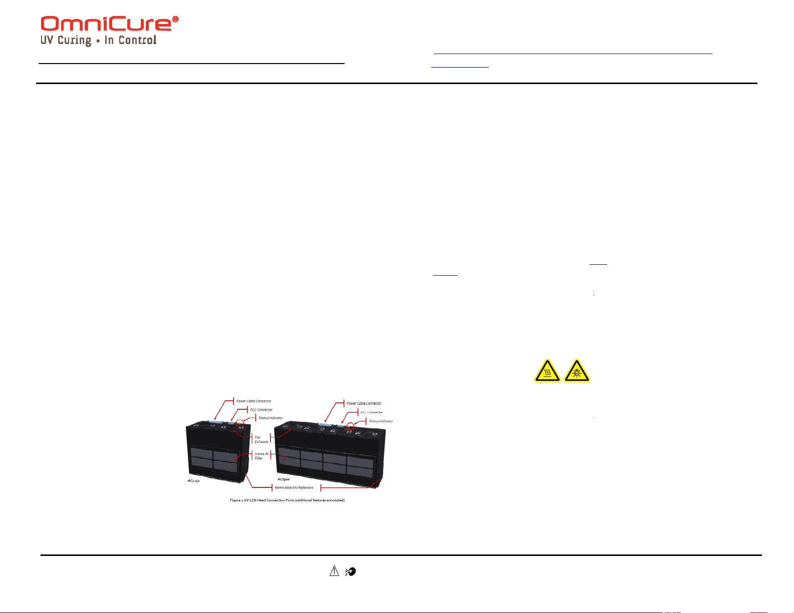
1. Attach the male end of the
2. Attach the male end of the
3. Make sure the power
power cable to the power
supply unit, and connect
1.
the female end of the
power cable to the UV LED
Head
PLC cable to the UV LED
Head (see
Figure
1).
supply unit is turned off.
2.
WARNING:
as clothing to protect exposed skin. Refer to user guide for more det
Side 1
in 2-3 minutes. Caution –
-
handling until
1.4 Using the LED Head
the PLC interface. Refer to Section 6 for Pin-Outs.
for light source operation.
Note: The light source will maintain a 2
head.
The UV LED Head indicator will illuminate to
amber indicating UV is on. When UV is off,
- 5nm, depending on model.
actuated by an external controller via
voltage is in the range of ~0.5
Tel: 1-905-821-2600
www.excelitas.com/omnicure

: Quick Start Guide
eater than 50
UV LED ON with 48V input voltage out of requirement
perating hours is < 9000
perating hours = between 9,000 and
perating hours is >10000
Make sure the AC power cord is securely plugged into a functional AC outlet and
Make sure that the circuit breaker on the power supply unit is not tripped. If so
Make sure all cable connections (power supply to UV LED Head) are secure.
Ensure that the power supply is switched on and the green LED indicator on the
Make sure the door lock electrical loopback on the PLC is install
If the system powers up but experiences a thermal fault during operation:
Ensure UV Head is installed with adequate clearance around intake and exhaust
clean with compressed air or replace with a new filter
2260 Argentia Road Mississauga ON L5N 6H7
Safety Precautions Booklet 035
http://www.excelitas.com/Pages/Product/OmniCure
AC7300.aspx
Ensure that the voltage levels on pins 2 and 3 of the PLC interface match the logic
Check the visual indicator for signs of a fault.
Attempt to clear the fault by toggling the voltage high on pin 14 of the PLC
interface or by pressing the “Clear Fault” button on the PLC controller.
system exhibits a fault condition with a slow
Make sure the input voltage is at least 46V (input voltage to the Head for the
purposes of powering the head is typically 48V
range input voltage will be indicated on the visible indicator on the UV LED
Clean the optical window of the UV LED Head as described in Section 9.3,
level of the UV LED Head is set to the correct level, using
If problems persist beyond these troubleshooting points, please contact Excelitas
Technologies Service Department (refer to Section 1
(refer to user guide for complete details)
and Electromagnetic Compatibility
has been tested and found to comply with product safety and
electromagnetic compatibility requirements. For a complete list of tests and f
representat
http://www.excelitas.com/Pages/Product/OmniCure.aspx
Council Directive 2014/35/EU
Council Directive 2014/30
Council Directive 2012/19/EU
Council Directive 2011/65/EU
RoHS
Excelitas Canada Inc.
Toll Free: 1
-
800-668-8752
OmniCure® AC7 Series
1.5 Understanding the LED Indicators
LED Indicator Condition
Steady green System Ready; no critical faults
Steady amber UV LED turned ON
Critical fault
Steady red
(~1x/second)
Slow flashing green
(~1x/second)
Slow flashing red Major or critical fault
Slow flashing amber
Fast flashing green Warranty status - o
Fast flashing amber
Fast flashing red Warranty status - o
Table 1 LED Indicator Status (UV LED Head)
1.6 Symptoms and Possible Causes
If the system fails to power up:
•
into the AC inlet on the power supply unit.
•
reset breaker.
•
•
front panel is lit.
•
•
ports.
• Ensure intake air filter is not clogged or obstructed.
• If filter is clogged, either
insert.
If the system powers up but does not emit UV:
• Temperature Fault
• LED Fault
• System Error
POST and Initialization
Input voltage is less than 46V or gr
is still functional.
Warranty status - o
10,0000
Warning – Refer to
prior to use. User Guide 035-00540R:
-00636R for all safety precautions
-AC7150-
V. Unit
ed properly.
• Check that the door lock loop is intact.
•
required to enable the LEDs.
•
If a fault condition has been detected:
•
If the
• Power-cycle the UV Head to clear.
If the light intensity is too low:
•
• Out-of-
Head with a slow flashing green.
•
“Cleaning the LED Head”.
• Verify that the intensity
the PLC Controller.
REGULATORY
Product Safety
The OmniCure AC7 Series
,
details, please contact your OmniCure
CE Marking
WEEE Directive China
•
•
•
•
-flashing red:
(46-50V DC)).
2, “Contact Information”).
or certification
ive or visit:
Low Voltage Directive
/EU EMC Directive
WEEE Directive
RoHS
RoHS FCC
Side 2
Tel: 1-905-821-2600
www.excelitas.com/omnicure
 Loading...