

Page 1
Technical Manual
Desktop & 19'' Rack Models
Version 4.00 Rev 0.03
Page 2

Introduction
This manual is to assist you with your support and servicing of Total Recall units. The manual will
be updated from time to time.
If you find any discrepancy, problems or you have something that you think should be in the
manual please Email us and we will include it in the next revision. This is a working document
which will continue to evolve. It is only with your help and feedback that we will make this a truly
helpful tool.
Thanks for your Help
Total Recall Technical Support Team.
V4.00 Rev0.03 July 05
Page 3

Table of Contents
1 WARRANTY 5
1.1 K
EEPING RECORDS OF SOLD TR UNITS / ACCESSORY 5
1.2 WHEN YOU CLAIM WARRANTY REPAIR 5
1.3 BEFORE YOU CONTACT US 5
1.4 WARRANTY STATEMENT 5
1.5 RETURNING FAULTY PRODUCT. 6
2 MAINTENANCE 6
3 OPENING TOTAL RECALL ENCLOSURE 7
3.1 DESKTOP MODEL 7
3.2 R
ACK MODEL 8
4 INTERNAL LAYOUT 9
4.1 D
ESKTOP MODEL 9
4.1.1 Lid Assembly 9
4.1.2 Base Assembly 9
4.2 19” RACK MOUNT MODEL 10
4.2.1 Top View 10
4.2.2 Bottom View 10
4.3 INTERNAL CABLE CONNECTION PC104 CM786 11
4.4 CABLE CONNECTION FOR PC104 CM786 12
5 REMOVING PARTS (DESKTOP) 13
5.1 REMOVE HARD DISK DRIVE 13
5.2 REMOVE THE CD-R / DVD DRIVE 14
5.3 REMOVE THE POWER SUPPLY 15
5.4 REMOVE THE MID-BOARD 16
5.5 R
EMOVE THE PC104 SMALL COMPUTER 17
5.6 REMOVE DSP CARDS 18
5.7 R
5.8 R
EMOVE LOWER DSP 19
EMOVE LCD SCREEN 20
6 REMOVING PARTS ( RACK MOUNT UNIT ) 22
6.1 REMOVE PC104 SMALL COMPUTER BOARD 22
6.2 R
EMOVE OR ADDING DSP BOARD 23
6.3 REMOVE TFT LCD & KEYPAD HOUSING 24
6.3.1 Removing TFT LCD 26
6.3.2 Refitting TFT LCD 27
6.4 R
EMOVE FAN & SPEAKER MOUNTING 27
6.5 REMOVE THE MIDBOARD 30
6.6 R
6.7 R
EMOVE THE HARD DISK DRIVE 30
EMOVE THE DVD / CD DRIVE 31
7 IDENTIFICATION OF TOTAL RECALL (DESKTOP MODEL) 32
7.1 LINE INPUT CONNECTORS 33
7.2 R
EMOTE ACCESS PORTS 34
Page 4

7.2.1 COM Port 1 for Modem 34
7.2.2 Network Port 34
7.3 DSP CONFIGURATION SETTINGS ( DESKTOP ONLY ) 35
8 IDENTIFICATION OF TOTAL RECALL (RACK MOUNT MODEL) 36
8.1 L
8.2 DSP
INE INPUT CONNECTORS 37
CONFIGURATION SETTINGS (RACK MOUNT MODEL) 38
8.3 CHANNEL NUMBERING 39
8.4 REMOTE ACCESS PORTS 41
8.4.1 COM Port 1 for Modem 41
8.4.2 Network Port 41
8.5 POWER SUPPLY OPTIONS 42
9 CABLE PIN ASSIGNMENTS 43
9.1 MODEM CABLE 43
9.2 NETWORK CROSSOVER CABLE 44
9.3 LCD & BACKLIGHTS 45
9.4 POWER CABLE SOCKET 46
9.5 ON/OFF SWITCH 46
10 SERIAL NUMBERS OF PARTS 47
10.1 TR SERIAL NUMBER LABEL 47
10.2 DSP SERIAL NUMBERS 47
10.3 MID-BOARD SERIAL NUMBERS 48
10.4 PC104 SMALL COMPUTER SERIAL NUMBER 48
10.5 POWER SUPPLY SERIAL NUMBER 49
10.6 FAN SERIAL NUMBER 50
10.7 DVD / CD-R SERIAL NUMBER 50
10.8 HARD DISK DRIVE SERIAL NUMBER 51
10.9 LCD SERIAL NUMBER 51
11 CONNECTING TOTAL RECALL 52
11.1 S
IGNAL SOURCES 52
11.2 START RECORDING - TRIGGER MECHANISM 52
11.2.1 VOX Trigger 52
11.2.2 Off-Hook 52
11.2.3 No line connected to a Channel 53
11.3 LINE INTERFACE CONNECTORS 53
12 CONNECTING TO THE TELEPHONE NETWORK TO RECORD CALLS 54
12.1 CONNECTING TO ANALOGUE TRUNK OR ANALOGUE EXTENSION LINES 54
12.2 C
ONNECTING TO A DIGITAL HANDSET USING HANDSET ADAPTERS/LOGGER PATCHES 56
12.4 CONNECTING TO A DIGITAL EXTENSION LINE 57
13 CLI & DTMF CAPTURE 58
14 CONNECTING TO 2-WAY RADIO 59
14.1 2
WAY RADIO MIXER ERROR! BOOKMARK NOT DEFINED.
15 4 CHANNEL DSP JUMPER SETTINGS 60
16 8 CHANNEL DSP JUMPER SETTINGS 61
V4.00 Rev0.03 July 05 2
Page 5

17 UPGRADING TOTAL RECALL TO HIGHER CHANNEL CAPACITIES 63
17.1 DESKTOP MODEL 63
17.2 19” RACK MOUNT MODEL 63
17.3 REQUIREMENTS 64
17.4 D
17.5 O
ISCONNECT POWER AND TELEPHONE LINES 64
PENING THE TOTAL RECALL CASE 64
17.6 FITTING THE ADDITIONAL DSP CIRCUIT BOARD 64
17.7 REASSEMBLY OF THE TOTAL RECALL 64
17.8 SOFTWARE ISSUES 64
18 NETWORK TCP/IP 65
18.1 ACCESSING TOTAL RECALL FROM REMOTE MANAGER THROUGH A FIREWALL 65
18.2 WHAT IF THE REMOTE PC IS BEHIND A LOCAL FIREWALL? 68
18.3 REMOTE MANAGER WILL NOT LIVE MONITOR 69
19 TOTAL RECALL WILL NOT BOOT 74
20 HELPFUL TOTAL RECALL KEYSTROKES 77
21 LCD SCREEN MESSAGES 77
22 SOUNDS AND NOISES 79
22.1 CONTINUOUS NOISE 79
23 PASSWORDS 79
24 DVD / CD DRIVE CLEANING 79
25 ARCHIVING PROBLEMS 79
25.1 KEYPAD LOCKUP WHEN ARCHIVING 79
25.2 AFTER ARCHIVE THE % ON THE HDD DID NOT CHANGE 80
25.3 TOTAL RECALL WILL NOT ARCHIVE TO CD. 80
25.3.1 “Loading CD” Message 80
25.4 “THIS CD COULD NOT BE LOADED” MESSAGE 80
25.4.1 “This CD has No free space” Message 80
25.4.2 “This CD may be damaged” Message 80
25.4.3 Tests to perform to determine CD-R drive problems: 81
25.4.4 Total Recall will not Search a CD. 81
26 RECORDING PROBLEMS 81
26.1 PROBLEM RECORDING WITH OFF HOOK 81
26.1.1 Continuous Recording 82
26.1.2 Call cut into Multiple Records of Varied length 82
26.1.3 Call cut into Multiple Records of Equal length 83
26.1.4 False recording on an adjacent channel. 83
26.1.5 Recording with Logger Patch 83
26.2 SEARCH AND REPLAY 84
26.2.1 Search Results 84
26.2.2 Testing the Speaker 84
26.2.3 Call Finished in Middle of Conversation 85
26.2.4 Remote Party very quiet 85
26.3 DTMF 85
V4.00 Rev0.03 July 05 3
Page 6

26.4 CLI 86
27 STANDARD BIOS SETUP 87
28 SPECIFICATIONS 88
29 SOFTWARE LICENCE AGREEMENT 90
V4.00 Rev0.03 July 05 4
Page 7

1 Warranty
To speed up the process of fault-finding and repair process detailed information about the faulty Total
Recall unit must be obtained from the customer and supplied to Tech Support with your enquiry.
1.1 Keeping Records of sold TR units / Accessory
As a reseller Arunta Comsec Pty Ltd requires you to keep records of units sold. These records will
contain no less than:
1: Date of Installation.
2: Item Sold.
2: Serial Number of the item and serial number of Total Recall if item is a spare part.
3: Channel configuration (if applicable).
4: Updates (software version & channel upgrades).
1.2 When you claim Warranty Repair
When you make a claim for warranty repair or replacement you will be asked to supply information
about the faulty product:
1: Date of Installation.
2: Serial Number of the item.
3: Nature of the fault.
4: Software version currently installed.
An RMA (Return Material Authorization) will be issued for the faulty product; this will be sent to
you by Fax, Email or with the new replacement parts. The faulty parts must be returned with a copy of
the RMA form to Arunta, Silverwater office as per the instruction on the bottom of the RMA form.
1.3 Before you contact us
It is always good practice to ensure that a unit has the latest software installed prior to contacting us
(except in cases where smoke has identified the fault). Quite often you will find that the new software
may have an enhancement that improves the performance of Total Recall. Generally the questions that
we will ask will be based on the latest software.
1.4 Warranty Statement
Normally you would contact your place of purchase or the distributor in your country for service (in
USA, Omnicron Electronics, www.omnicronelectronics.com
) for service. All Total Recall products
are covered by a 12-month depot warranty from date of original shipment. In the event that a
V4.00 Rev0.03 July 05 5
Page 8

Warranty claim is to be handled by the manufacturer, your request must be communicated to Arunta
in writing. A Return Merchandise Authority (RMA) form will be sent to you for appropriate
completion and return before shipment of warranty replacement goods. The RMA form should be
enclosed with return of faulty goods. Arunta will process no warranty claim without the prior
authorisation of the Technical Services Manager. Dead on Arrival (DOA) units will be replaced
immediately following authorization.
Should product become faulty or otherwise malfunction, Arunta will repair or replace the product at
its discretion. All component parts will be supplied by Arunta and shipped to the Reseller via courier
service.
If a ‘part’ of the product is replaced under warranty, that ‘part’ must be retained by the Reseller for a
period of 12 months during which time, Arunta may, at its discretion, request the inspection of the
faulty part(s) or, in certain circumstances, the return to base of the faulty ‘part’. If the Reseller is
unable to produce faulty parts for which warranty replacements have been provided, then the Reseller
will be required to pay to Arunta the value of the replacement parts, as determined by Arunta.
All Total Recall serial numbers and parts serial numbers will be logged by Arunta, effective the date
of shipment.
Further details are available in the Total Recall Product Warranty document.
1.5 Returning Faulty Product.
If product needs to be returned to Arunta at any time, a Return Merchandise Authorisation (RMA)
number must first be obtained from Arunta. Returned products will not be processed if an RMA
number is not first obtained. The cost of returning any Total Recall product to Arunta is the
responsibility of the Reseller.
2 Maintenance
Total Recall needs regular maintenance to ensure its performance is maintained. As with any
computing device Total Recall has a fan that provides airflow across the processor to keep it cool and
a filter to ensure that the air is clean. Every month the filter will need to be washed in warm soapy
water and then rinsed thoroughly and allowed to dry completely prior to being replaced. New filters
are available.
V4.00 Rev0.03 July 05 6
Page 9
3 Opening Total Recall Enclosure
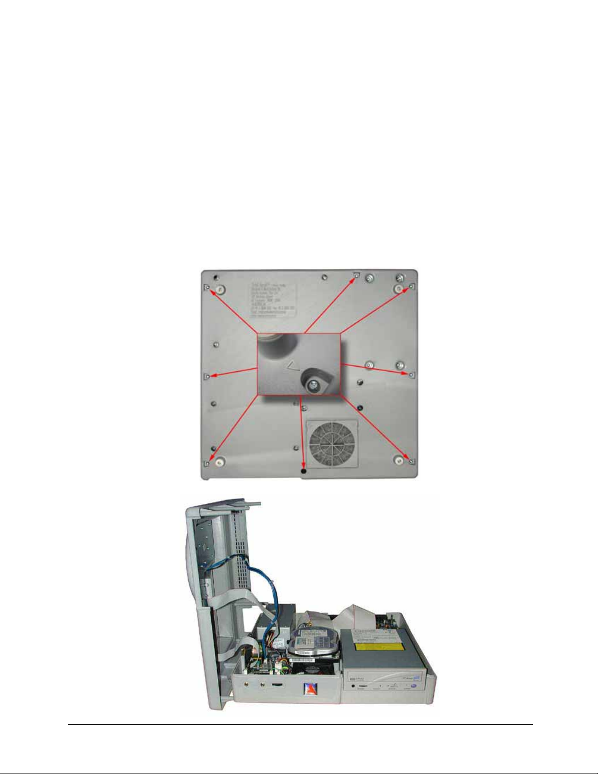
3.1 Desktop Model
To open the Total Recall ABS enclosure invert the unit onto a clean and clear flat surface. Take
general precautions to prevent damage to the LCD display from objects underneath.
Unscrew the eight (8) M3 x 8mm pan head screws located in the recesses marked with an >.
Holding both halves of the case together return the case to the normal position.
Slowly lift upwards the top half of the Total Recall case until the internal studs inside the top case are
clear of the lower case. The right hand side can now be rotated 180 degrees to the left so that the
inverted top half lies next to the bottom half. Do not attempt to move the top half any further until the
interconnecting cables have been disconnected.
V4.00 Rev0.03 July 05 7
Page 10
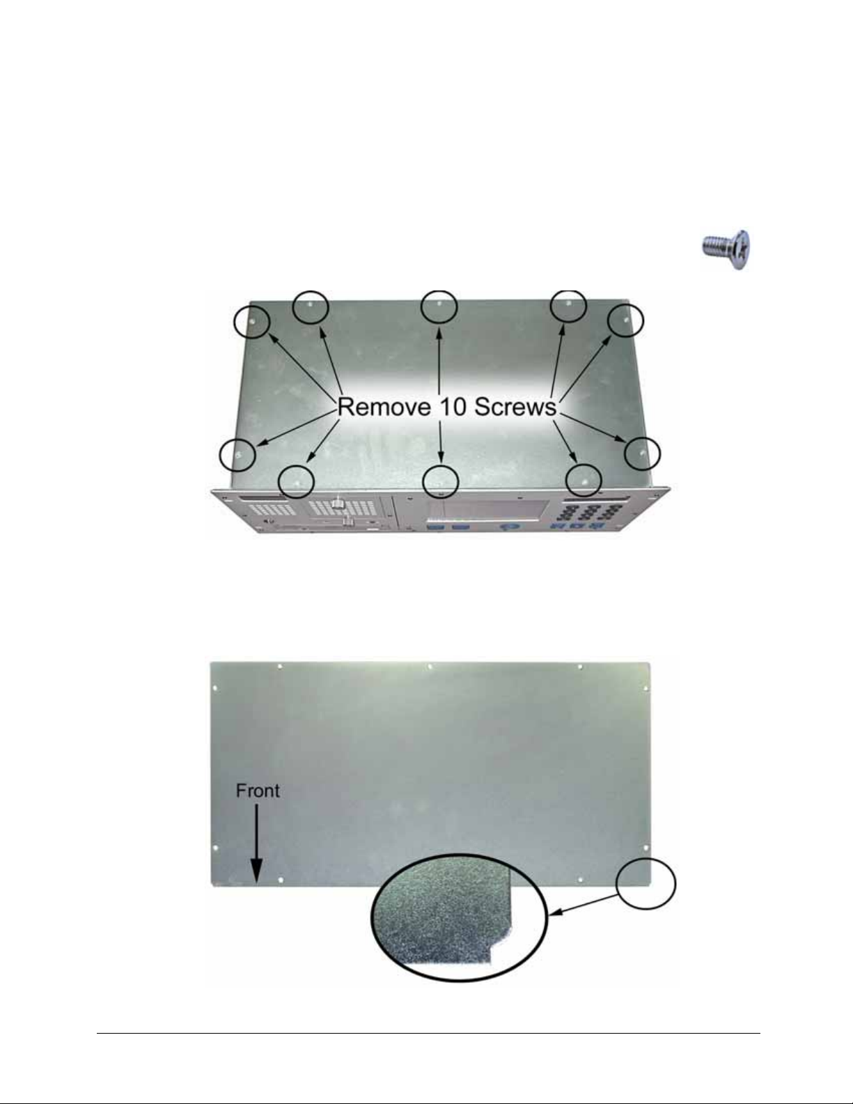
3.2 Rack Model
To open the Total Recall metal enclosure, there are two covers one on the top and one on the bottom.
To remove either cover there are ten (10) Phillips head screws that secure these covers as indicated in
the diagram below.
When replacing the Top or Bottom Cover Plate ensure that the corners, with the small cut-outs are
facing the front of the unit.
Total Recall Top & Bottom Cover Plate
V4.00 Rev0.03 July 05 8
Page 11
4 Internal Layout
4.1 Desktop Model
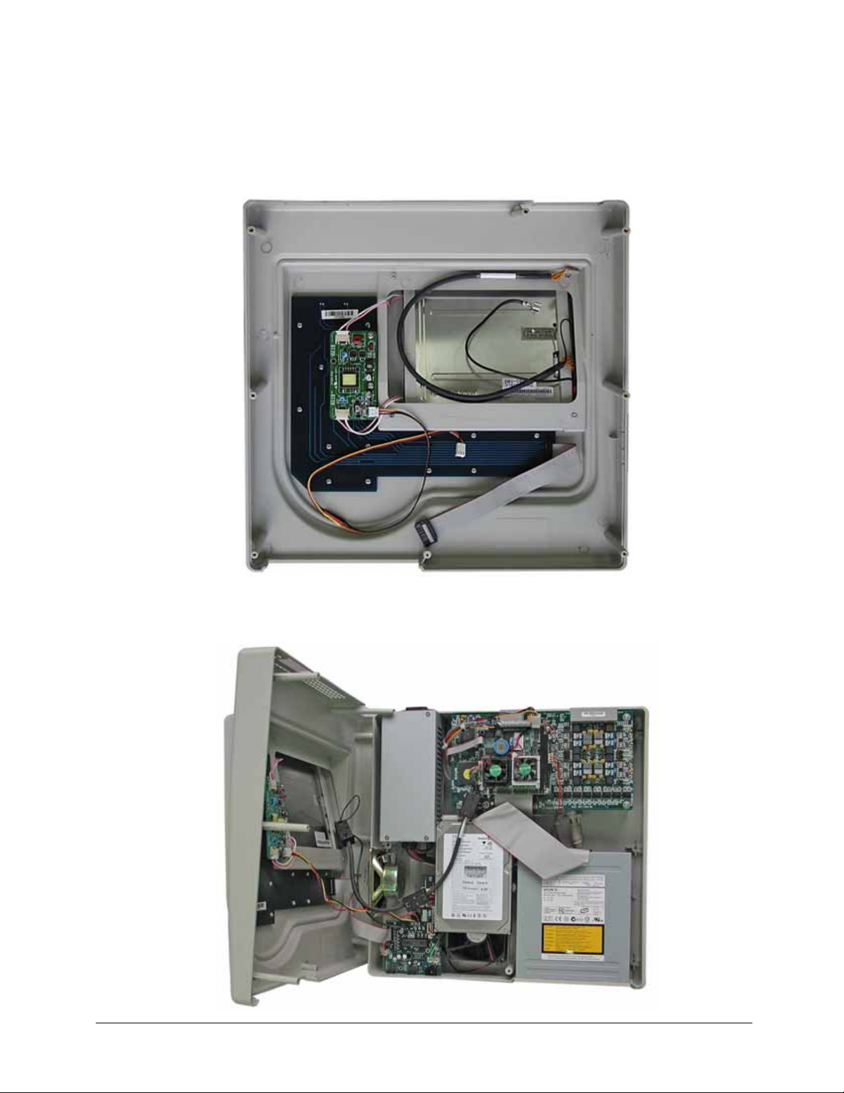
4.1.1 Lid Assembly
4.1.2 Base Assembly
V4.00 Rev0.03 July 05 9
Page 12
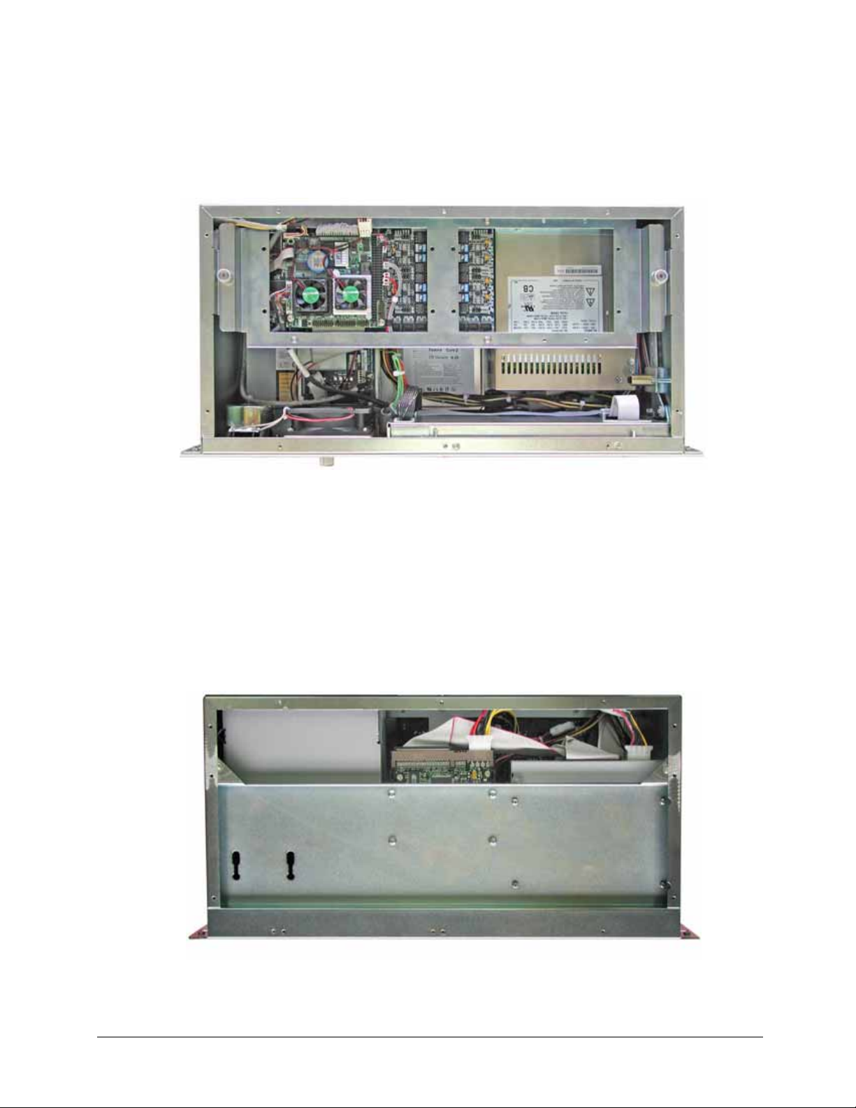
4.2 19” Rack Mount Model
4.2.1 Top View
4.2.2 Bottom View
V4.00 Rev0.03 July 05 10
Page 13
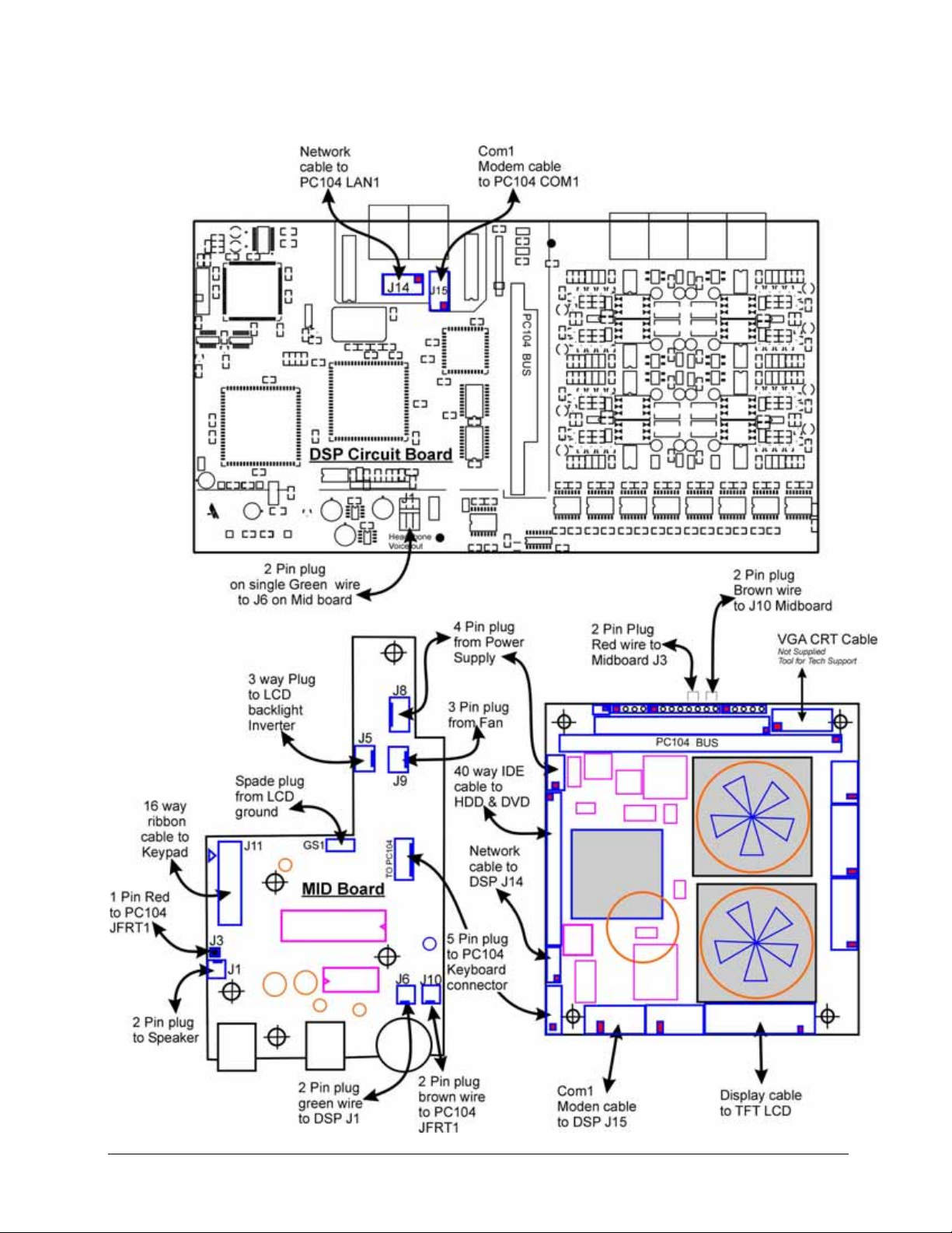
4.3 Internal Cable Connection PC104 CM786
V4.00 Rev0.03 July 05 11
Page 14
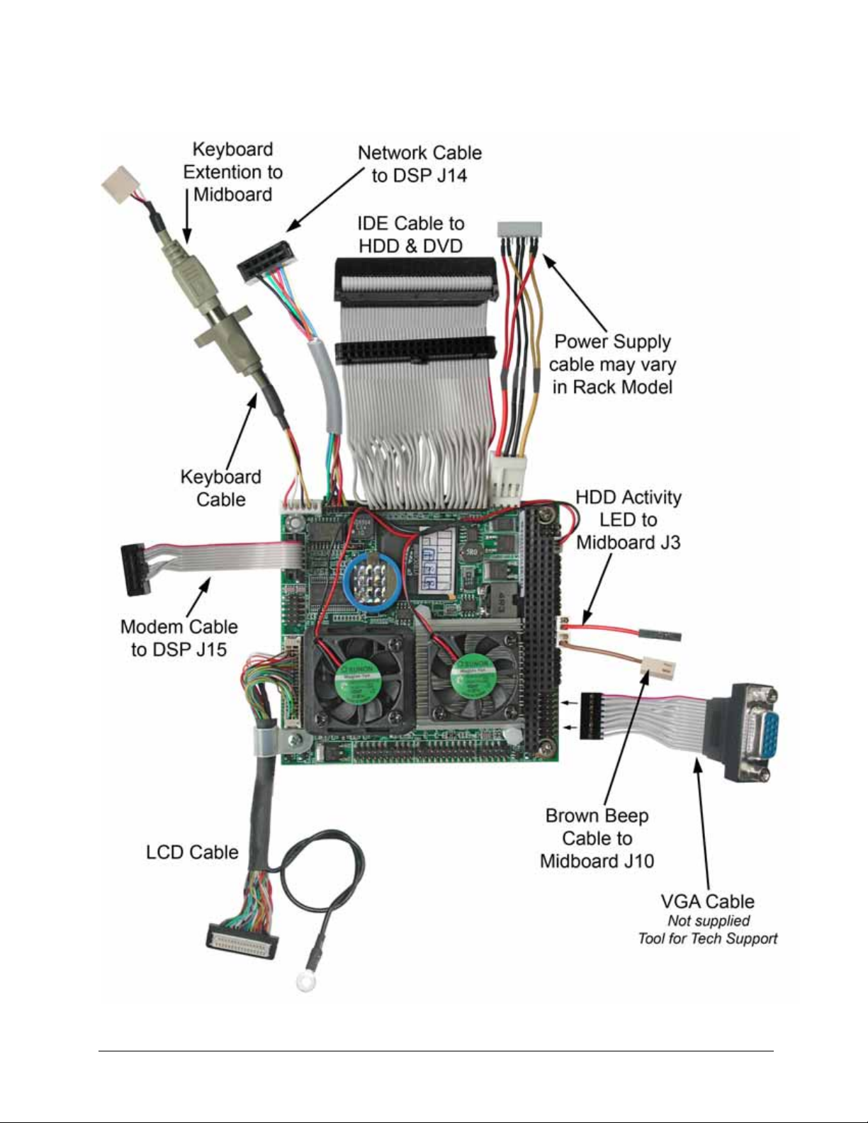
4.4 Cable Connection for PC104 CM786
V4.00 Rev0.03 July 05 12
Page 15
5 Removing Parts (Desktop)
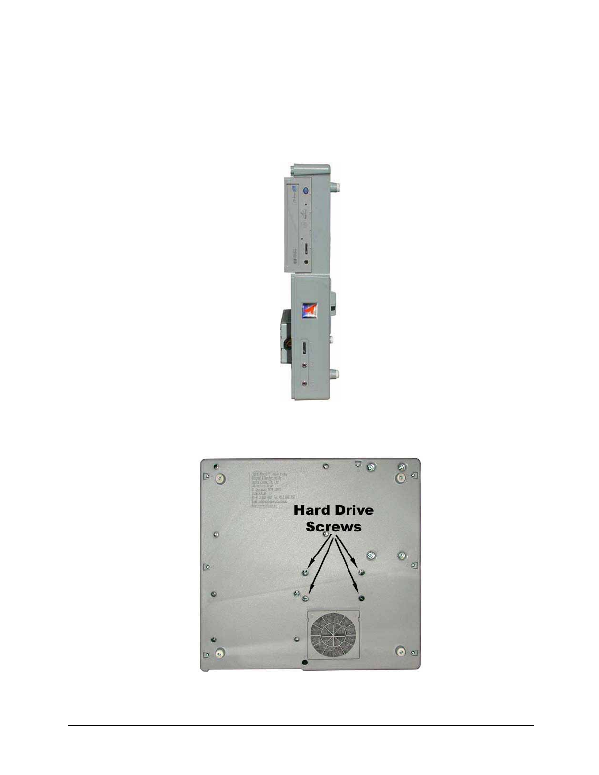
5.1 Remove Hard Disk Drive
After opening the TR case (Section 2 above) disconnect the Top shell from the base and stand the
base on its left side.
Unscrew 4 screws from Hard Disk Drive. see attached diagram. Hold HDD while unscrewing.
Holding the HDD, lay the TR base flat on to the bench and disconnect the IDE ribbon cable and the
power plug.
V4.00 Rev0.03 July 05 13
Page 16
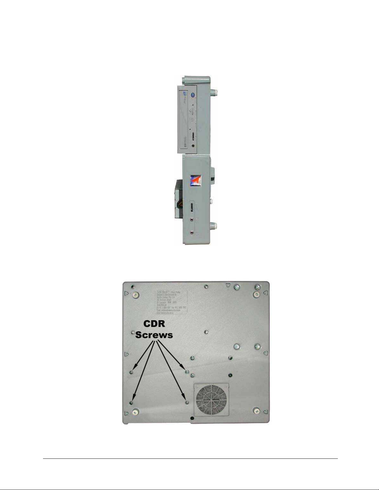
5.2 Remove the CD-R / DVD Drive
After opening the TR case (Section 3 above) disconnect the Top shell from the base and stand the
base on its left side.
Unscrew 4 screws (M4 x 8 mm Phillips head) from DVD / CD drive. See attached diagram. Hold
DVD / CD drive while unscrewing the screws.
Holding the DVD / CD drive, lay the TR base flat on to the bench and disconnect the IDE ribbon
cable and the power plug.
V4.00 Rev0.03 July 05 14
Page 17

5.3 Remove the Power Supply
After opening the TR case (Section 3 previously) disconnect the Top shell from the base and stand
the base upside down.
Unscrew 4 screws (M4 x 8 mm Phillips head) from the Power Supply. See attached diagram.
Holding the Power Supply lay the TR base flat on to the bench.
Disconnect the power plug from the HDD and the CDR.
Disconnect the power plug from the mid-board J3.
Disconnect the power plug from the PC104 fly lead.
Remove the Power Supply.
V4.00 Rev0.03 July 05 15
Page 18
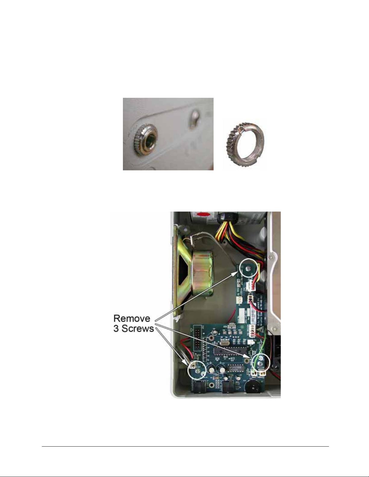
5.4 Remove the Mid-board
To remove the Mid-board first undo the 2 knurled nuts on the front of the TR unit.
Then unscrew the 3 Phillips head screws as shown.
To fit a new Midboard see the cable connection diagram in Section 4.3.
V4.00 Rev0.03 July 05 16
Page 19
5.5 Remove the PC104 Small Computer
The PC104 CM786 small computer board is located on top of the DSP card.
To remove first remove the four (4) screws at each corner.
Grip the PC104 card on both sides of the PC104 connector, gently ease the card from front to back
until the card releases from the DSP connector.
Then carefully remove the cables.
Note: The cable assignment can be found in Section 4.3 & 4.4
Caution: When reassembling the PC104 do NOT lay the IDE ribbon cables across the CPU
cooling fans. Run the IDE cable under the PC104 to allow free air circulation.
V4.00 Rev0.03 July 05 17
Page 20
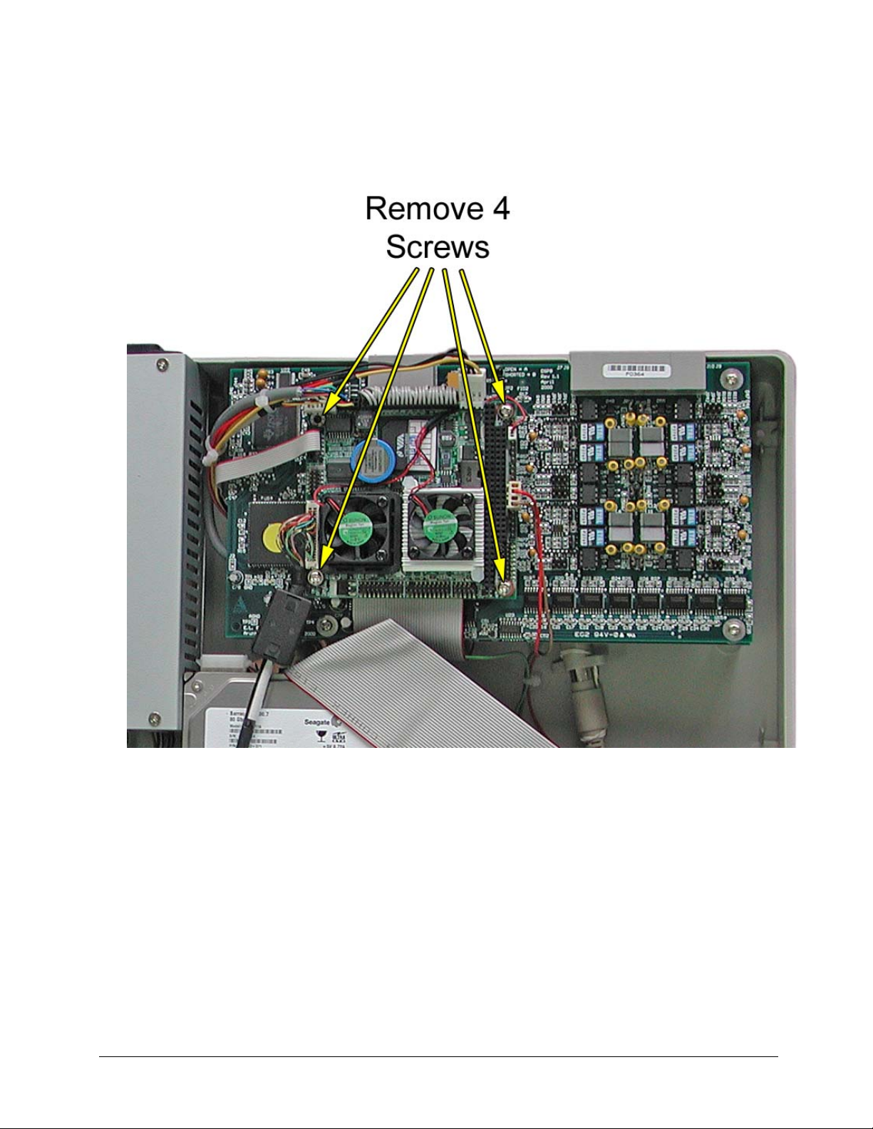
5.6 Remove DSP cards
First the PC104 small computer board must be removed. See Section 5.5 above.
To remove the top DSP card (if fitted) unscrew 4 Phillips head screws as shown.
Grip the DSP card on both sides of the PC104 connector, gently ease the card from front to back
until the card releases from the PC104 connector.
Caution: Protect the PC104 connector pins on the under side of the DSP card.
V4.00 Rev0.03 July 05 18
Page 21
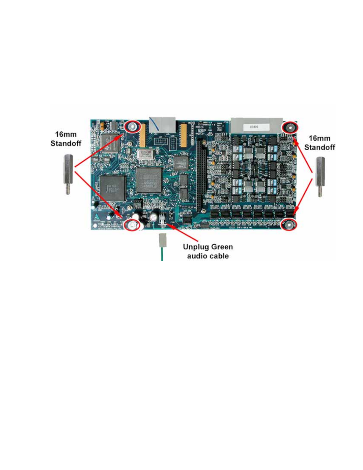
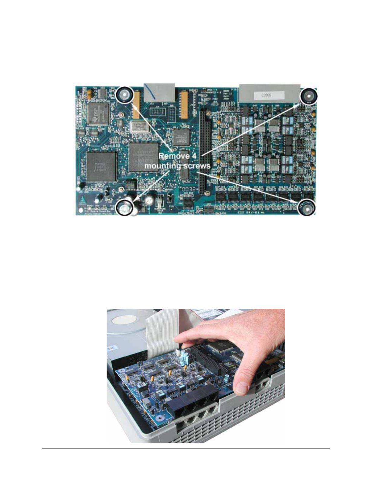
5.7 Remove Lower DSP
First remove the PC104 small computer board from the DSP as per instructions in Section 5.5
Remove the top DSP, if fitted as per instructions in Section 5.6.
Then unscrew 4 hexagon Standoffs that secure the DSP assembly to the TR base.
V4.00 Rev0.03 July 05 19
Page 22
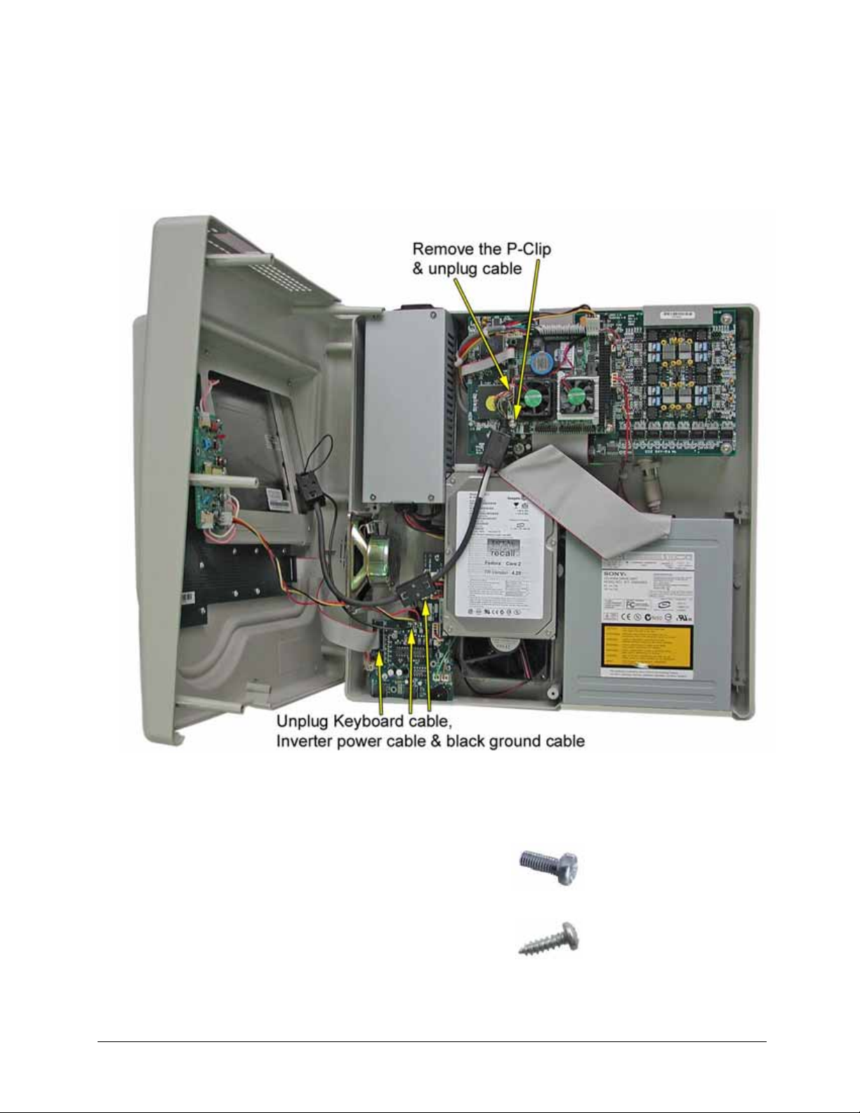
5.8 Remove LCD Screen
After opening the enclosure see Section 3.1 unscrew the P-Clip holding the LCD cable to the
PC104, and unplug the cable.
Remove the top enclosure from the base and lay on a flat surface.
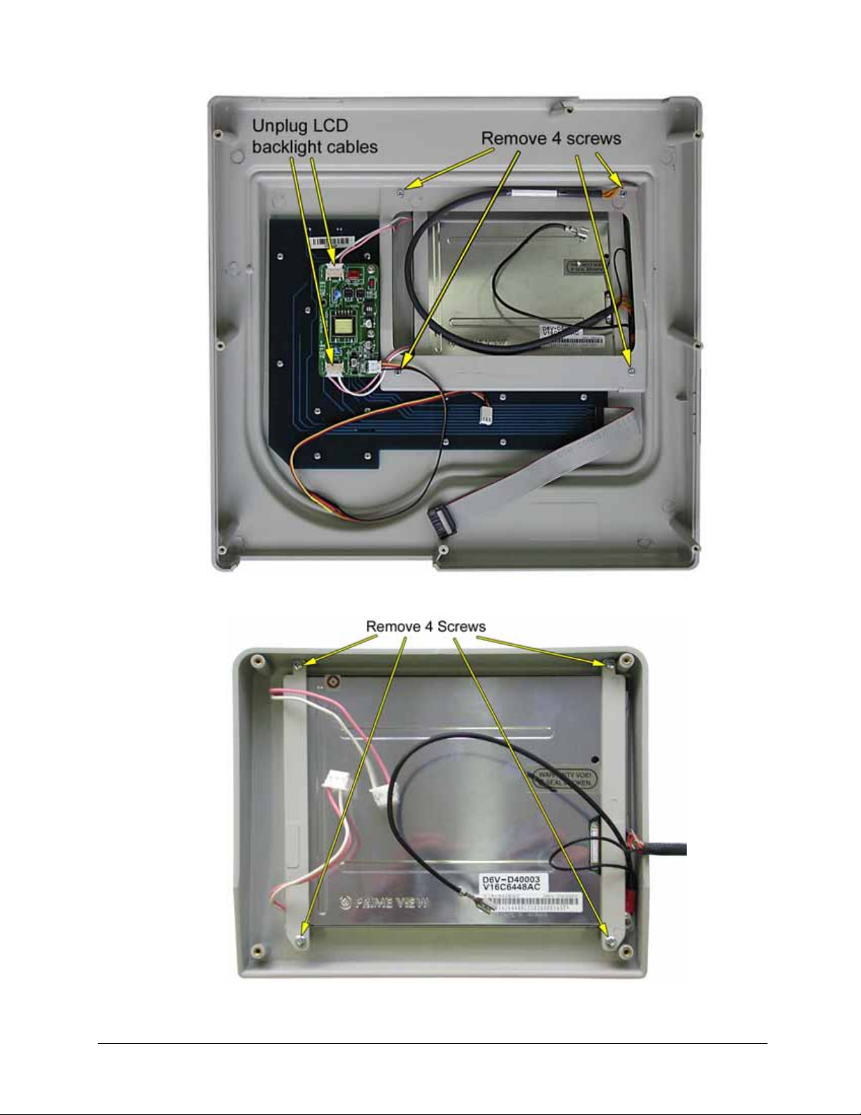
Unplug the two LCD backlight cables (pink & white). See photo below.
Remove the 4 screws that secure the LCD housing.
Carefully lift the top enclosure from the LCD housing.
Remove the 4 screws from the LCD mounting straps.
Lift the LCD from the mounting.
Note: When reassembling the LCD ensure the correct screws are used.
V4.00 Rev0.03 July 05 20
Page 23
LCD Housing
V4.00 Rev0.03 July 05 21
Page 24
6 Removing Parts ( Rack Mount Unit )
To open the Rack enclosure see Section 3.2
6.1 Remove PC104 Small Computer Board
Remove 4 mounting screws from the four corners of the PC104.
Grip the PC104 across the PC104 Bus connector and gently ease it back and forward to release it
from the DSP Bus connector.
Carefully unplug all the cables from the PC104 board.
1: Grey 40 way IDE cable.
2: Power cable 4 way (red, black, black, red).
3: Network cable 7 wire multi colour.
4: Keyboard Cable 4 wire (red, white, black, yellow).
5: Com1 Cable (Modem) 10 way grey ribbon cable.
6: LCD cable multi strand multi colour.
7: Brown Beep cable.
8: Red HDD activity LED cable.
When reconnecting cables see Section 4.3 & 4.4.
V4.00 Rev0.03 July 05 22
Page 25
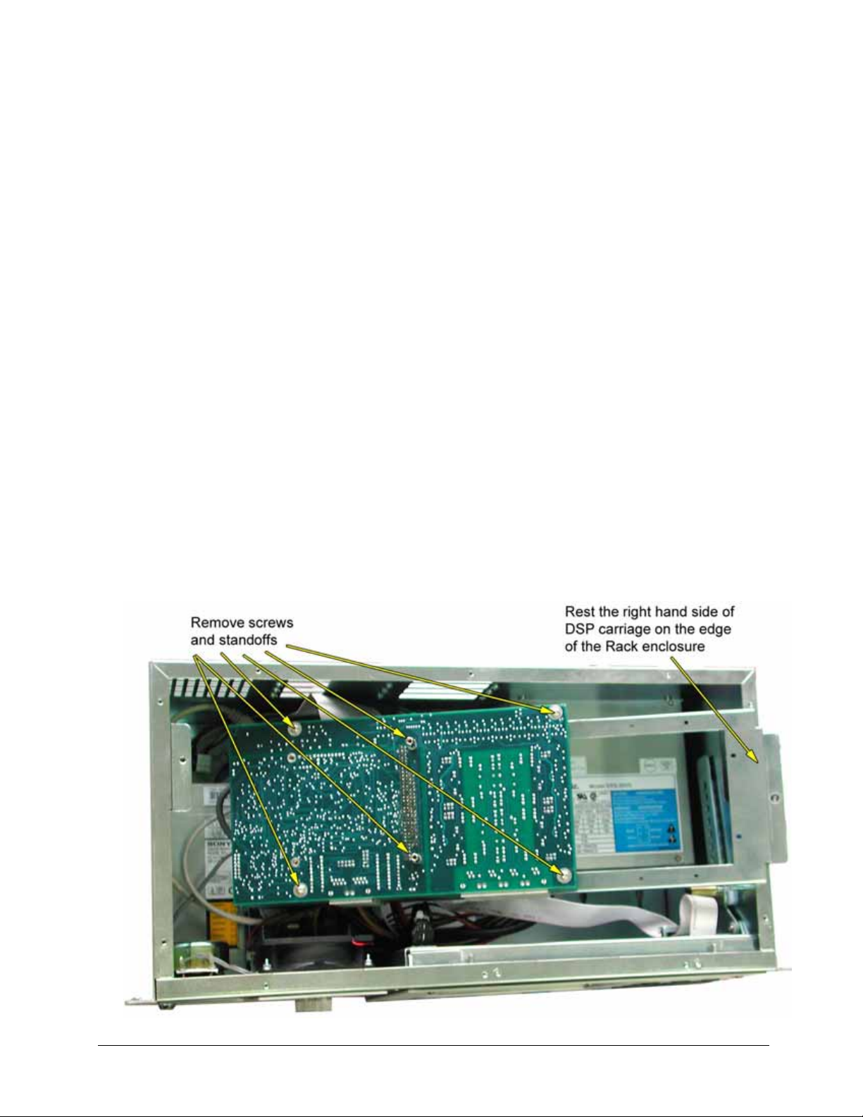
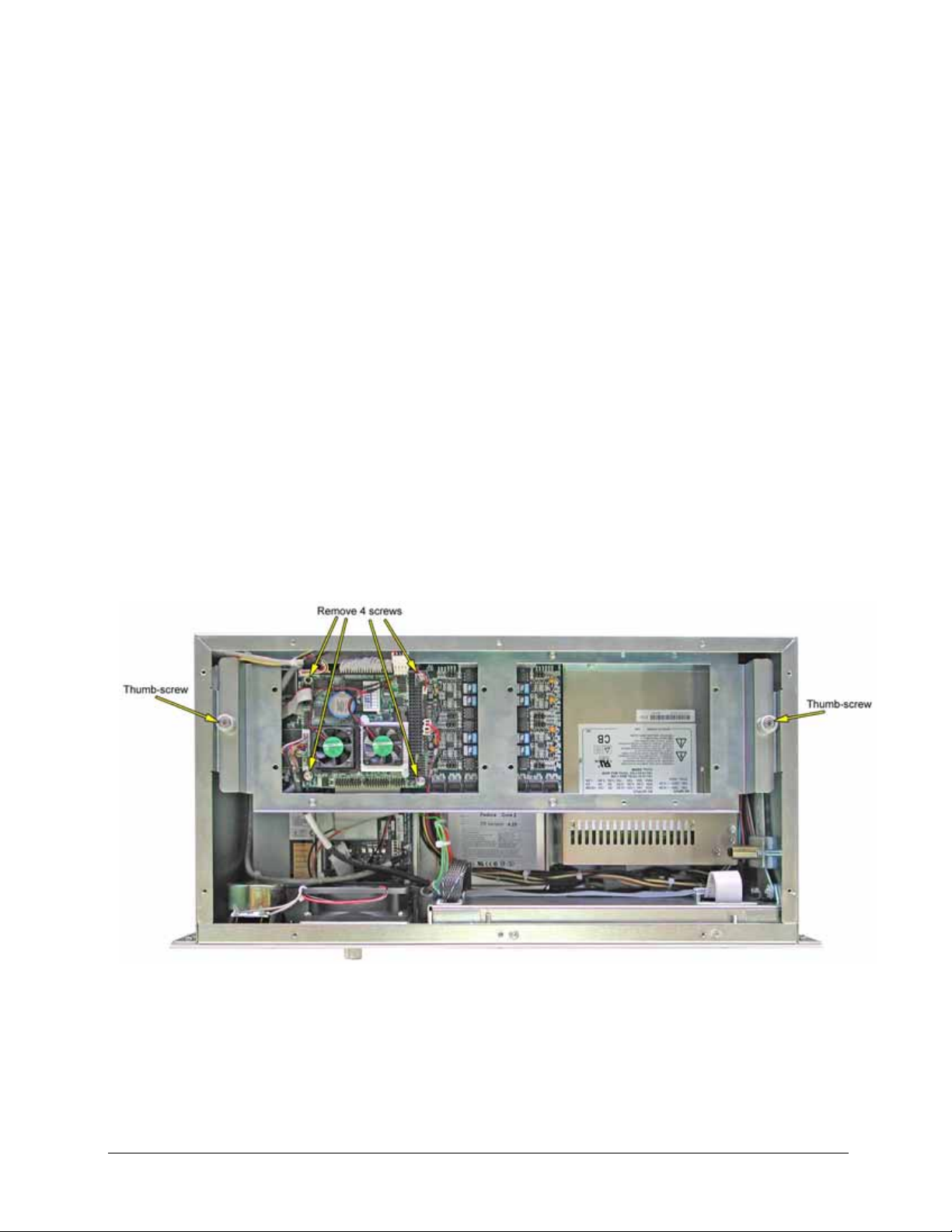
6.2 Remove or Adding DSP Board
The DSP board are all housed under a suspended carriage which is held in place by a thumb screw
on either side. See photo above.
Depending of the configuration of the unit 4, 8, 12, 16, 20, 24, 28, 32 channel there may be 1, 2, 3,
or 4 DSP cards fitted. If there is only one and it is to be removed the PC104 will need to be
removed first.
If there are more than one DSP and another DSP is to be added or removed there is no need to
remove the PC104.
To add or remove a DSP first remove the cover plate from the underside of the Rack Mount unit.
Then unplug the IDE cable from the DVD drive and the HDD.
Then unscrew the two thumb-screws that hold the DSP carriage.
Gently lift the carriage assembly and rotate it towards you to expose the underside of the DSP
boards. Using some soft foam or bubble wrap under the carriage assembly to protect the PC104
lay it down into the enclosure resting the right hand side of the carriage on the edge of the Rack
enclosure.
Now DSPs can be added or removed.
Remove screws and standoffs grip the DSP on either side of the PC104 Bus connector and gently
ease it back and forward to release it from the other PC104 Bus connector.
V4.00 Rev0.03 July 05 23
Page 26
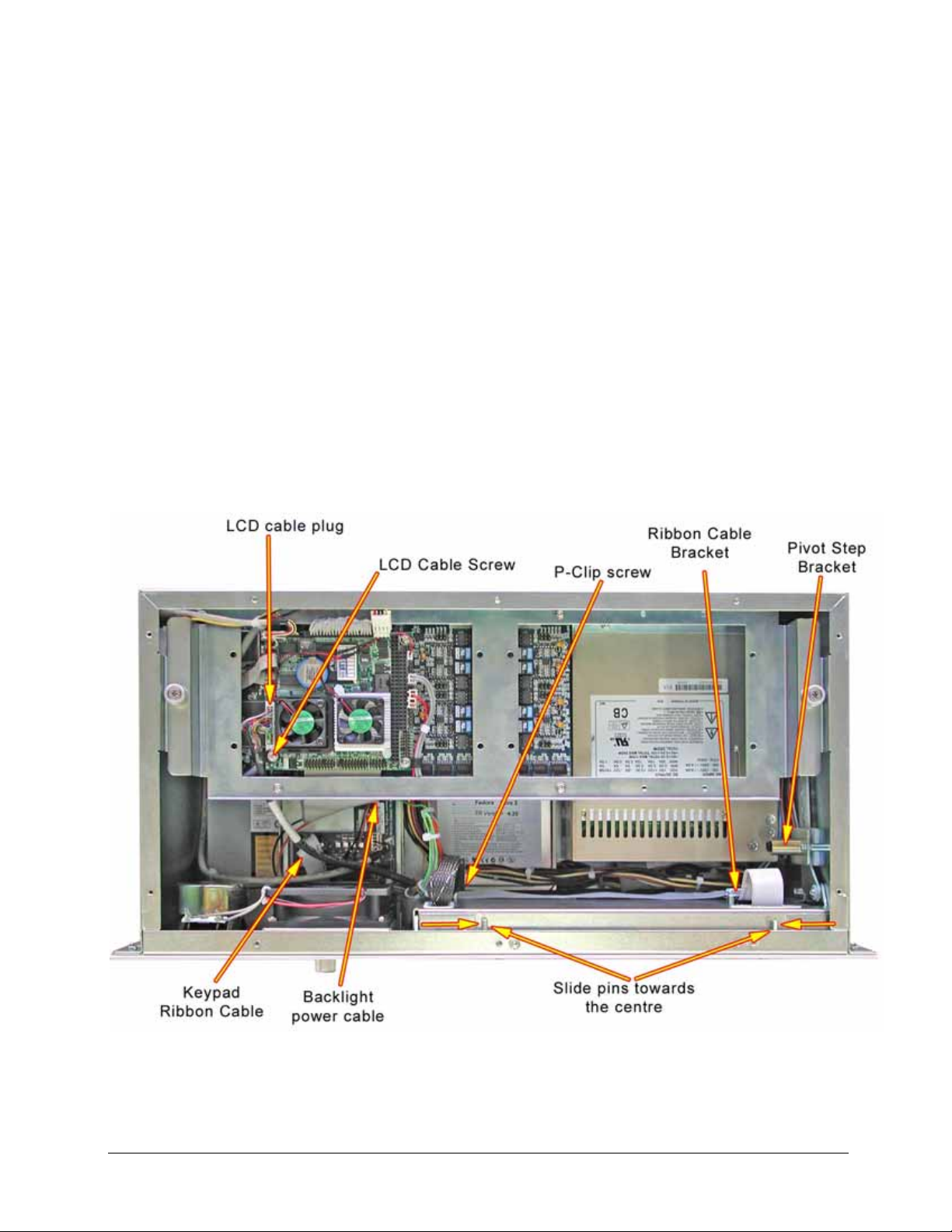
6.3 Remove TFT LCD & Keypad Housing
To open the Rack enclosure see Section 3.2
To remove the LCD and Keypad Housing:
1: Remove LCD cable retaining screw and unplug cable plug from the PC104.
2: Unplug LCD Backlight power cable and the Keypad ribbon cable from the Midboard.
3: Remove the P-Clip screw and the Ribbon cable bracket.
4: Remove the Pivot Step Bracket by removing the two screws.
5: Pivot open the LCD housing a small amount and then slide the two Pins towards the centre
about 10mm until the LCD housing releases from the Rack enclosure.
V4.00 Rev0.03 July 05 24
Page 27
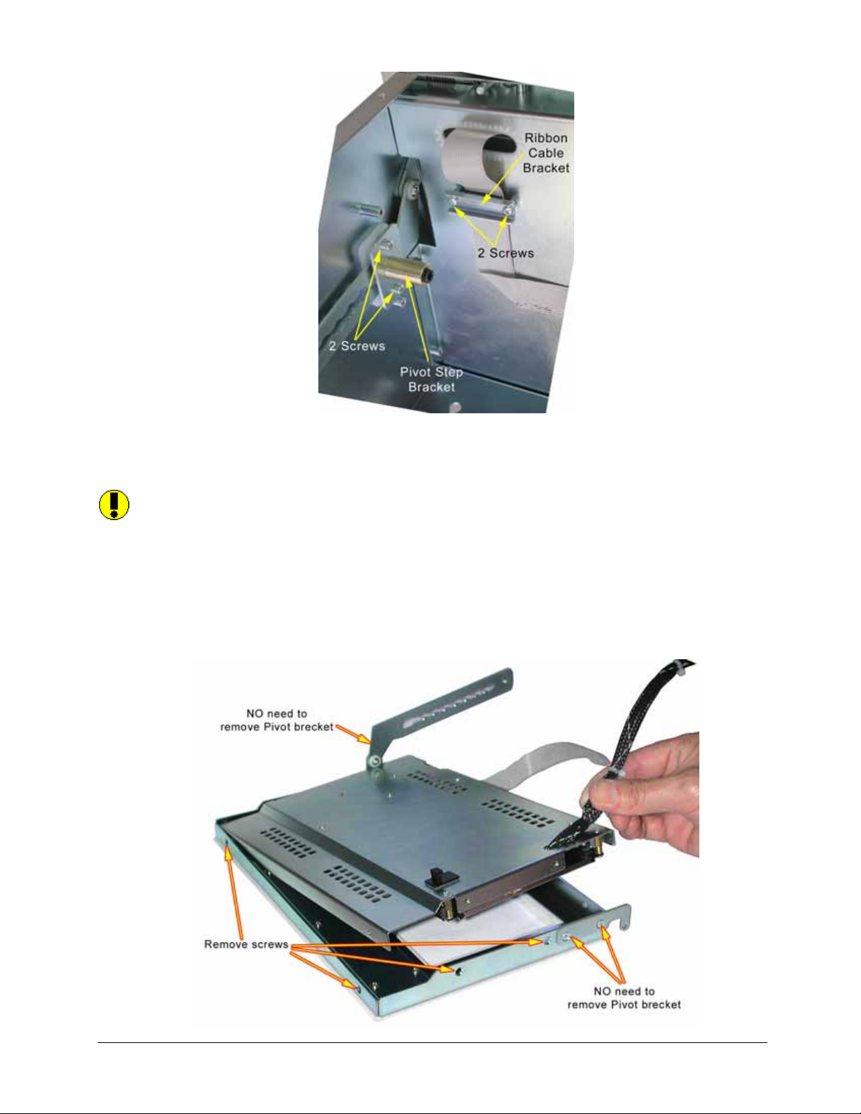
6: Gently ease the LCD cables and ribbon cables through the apertures and lay the LCD housing
face down onto a soft nonabrasive surface.
Note: There is NO need to remove the Face Plate or the two pivot brackets to get access to
the LCD or the Keypad.
7: Remove 9 Countersunk Screws from the edge of the LCD Housing, 3 on the top edge and two
on the other three edges.
8: Holding the LCD cable gently ease the back plate up away from the Keypad plate.
V4.00 Rev0.03 July 05 25
Page 28
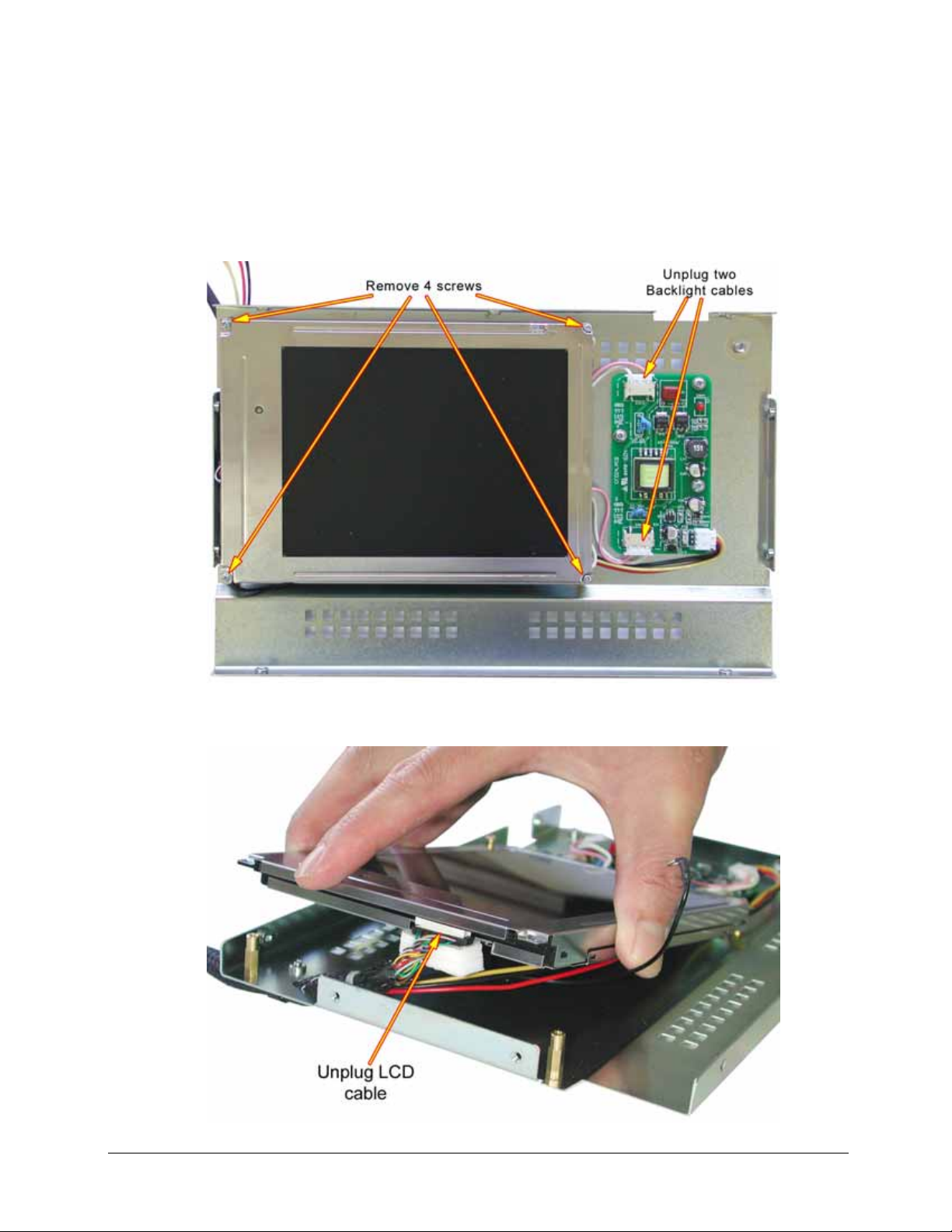
6.3.1 Removing TFT LCD
Lay LCD / Keypad back plate on a flat surface with the LCD face up.
Unplug two (2) LCD backlight cable plugs from the Inverter.
Remove four (4) 2mm screws from each corner of the LCD.
Lift LCD so you can get access to the LCD cable plug, and gently ease the plug from the socket.
V4.00 Rev0.03 July 05 26
Page 29

6.3.2 Refitting TFT LCD
When refitting the LCD care must be taken to ensure that the fine wires of the LCD cable near the
plug are kept well inside the metal rim of the housing, to prevent damage to the wires.
Fit the Earth lug under the retaining screw and on top of the LCD bezel.
6.4 Remove Fan & Speaker Mounting
First remove the Top cover plate of the Rack enclosure see Section 3.2
Lay the TR Rack Enclosure on it back. & Remove the front face plate by;
Using a Hexagon (Alan Head) drive remove 13 screws from the face panel.
Note: There is no need to remove the six screws from the face plate of the LCD / Keypad Pivot
panel.
Remove the Filter Cover.
V4.00 Rev0.03 July 05 27
Page 30

Remove 4 Countersunk screws from the Fan / Speaker Housing.
Unplug Red, Brown and Green cables from the PC104.
Remove screw from P-clip holding the LCD cable. Unplug the LCD cable.
V4.00 Rev0.03 July 05 28
Page 31

Press clip and unplug Power Switch plug.
Unscrew the two Thumb Screws from the PC104 / DSP cradle and tilt the cradle on its side to gain
access to the Midboard.
Unplug the Keypad Extension cable plug see photo below..
Unplug the Keypad Ribbon Cable from the Midboard.
Unplug The LCD Backlight Power cable from the Midboard.
Unplug the Midboard Power Cable from the Midboard.
V4.00 Rev0.03 July 05 29
Page 32

The Fan / Speaker Hosing can now be slid out from the front of the Rack Enclosure.
6.5 Remove the Midboard
The Midboard is mounted to the Fan / Speaker Housing, to remove the Midboard see Section 6.4
above.
6.6 Remove the Hard Disk Drive
To remove the Hard Disk Drive first remove the Top and Bottom enclosure covers, see Section 3.2
Unplug the IDE cable and the Power cable from the HDD.
Stand the Rack Enclosure on one end, holding the HDD remove the 4 screws.(6-32 Pan head x ½”)
V4.00 Rev0.03 July 05 30
Page 33

6.7 Remove the DVD / CD drive
To remove the DVD or CD Drive first remove the Top and Bottom enclosure covers, see Section 3.2
Unplug the IDE cable and the Power cable from the DVD / CD Drive.
Stand the Rack Enclosure on one end, holding the DVD / CD Drive remove the 4 screws.(M3 Pan
head x 6mm)
V4.00 Rev0.03 July 05 31
Page 34

7 Identification of Total Recall (Desktop model)
V4.00 Rev0.03 July 05 32
Page 35

7.1 Line Input Connectors
4 channel DSP are BLACK 8 channel DSP are GREY
The recorder will be configured as either a 4, 8, 12 or 16-port unit. The connectors for the
telephone line interface are standard RJ11C / RJ12 / RJ14 (6P 6C) telephone sockets.
(They get called different names in different countries).
The 2-wire analogue line interface:
4 Channel DSP (BLACK coloured RJ connectors viewed from the outside): 2 wire connection
uses pins 3 & 4, (the centre 2 pins) See diagram
Each connector has only one (1) x 2 wire input.
8 Channel DSP (GREY coloured RJ connectors viewed from the outside); 2 wire connections,
Line 1 is pins 3 & 4 (centre 2 pins), Line 2 is pins 2 & 5 See diagram
8 channel DSP boards each connector has two (2) x 2 wire inputs.
V4.00 Rev0.03 July 05 33
Page 36

7.2 Remote Access Ports
7.2.1 COM Port 1 for Modem
Com 1 serial port (RS-232) using a standard RJ45 socket (8P 8C) for connection to a Modem for
remote access. A Modem to Total Recall cable is supplied with each Total Recall unit. The Pin
assignments for this cable can be found in Section 9.1.
The Modem that is recommend for use with Total Recall is a V92 56K external serial modem.
The faster the modem the better. The modems will negotiate the optimum speed that they
can communicate at.
You cannot use an internal modem with Total Recall.
Total Recall will support all external modems supported by Linux which is almost all of them.
For more details on modem compatibility read http://www.tldp.org/HOWTO/Modem-HOWTO-2.html
Do NOT use a Null Modem cable with crossed wires the cable should be straight through.
7.2.2 Network Port
The Network port is an IEEE802.3U compatible 10/100 Base-T interface using a standard RJ45
socket (8P 8C) for connection to a Net Switch, Hub or other network device, for remote access. A
Network Crossover cable is supplied with each Total Recall unit. The Pin assignments for this
cable can be found in Section 9.2.
V4.00 Rev0.03 July 05 34
Page 37

7.3 DSP Configuration Settings ( Desktop only )
To set the configuration for the DSP there are two Shorting Link Jumpers, JP1 and JP2. These are
used to tell the system which is the first set of channels and which is the second set of channels.
The lower DSP is DSP 1. NO Jumper Link on either JP1 or JP2.
The top DSP is DSP 2. Jumper Link on JP1 only.
DSP 1 with NO Jumper Link fitted is the DSP that has the Green audio cable connected.
V4.00 Rev0.03 July 05 35
Page 38

8 Identification of Total Recall (Rack Mount model)
Rear view Rack Mount fitted with Dual Hot-swap Power Supply
V4.00 Rev0.03 July 05 36
Page 39

8.1 Line Input Connectors
4 channel DSP are BLACK 8 channel DSP are GREY
The recorder will be configured as either a 4, 8, 12 or 16-port unit. The connectors for the
telephone line interface are standard RJ11C / RJ12 / RJ14 (6P 6C) telephone sockets.
(They get called different names in different countries).
The 2-wire analogue line interface:
4 Channel DSP (BLACK coloured RJ connectors viewed from the outside): 2 wire connection
uses pins 3 & 4, (the centre 2 pins) See diagram
Each connector has only one (1) x 2 wire input.
8 Channel DSP (GREY coloured RJ connectors viewed from the outside); 2 wire connections,
Line 1 is pins 3 & 4 (centre 2 pins), Line 2 is pins 2 & 5 See diagram
8 channel DSP boards each connector has two (2) x 2 wire inputs.
V4.00 Rev0.03 July 05 37
Page 40

8.2 DSP Configuration Settings (Rack Mount model)
To set the configuration for the DSP there are two Shorting Link Jumpers, JP1 and JP2. These are
used to tell the system which is the first set of channels and which is the second set of channels etc.
The Top DSP is DSP 1. NO Jumper Link on either JP1 or JP2.
The next DSP is DSP 2. Jumper Link on JP1 only.
The next DSP is DSP 3. Jumper Link on JP2 only.
The next DSP is DSP 4. Jumper Link on JP1 & JP2.
DSP 1 with NO Jumper Link fitted is the DSP that has the Green audio cable connected.
V4.00 Rev0.03 July 05 38
Page 41

8.3 Channel Numbering
Each input socket is numbered with an embossed figure in the plastic case. There is a maximum of
8 sockets so the configuration for the different TR units are:
----------------------------------------------------------------------------------------------------------------------4 channel: 1 = line 1 ┐
2 = line 2 │ 4 channel DSP
3 = line 3 │
4 = line 4 ┘
----------------------------------------------------------------------------------------------------------------------8 channel 1 = line 1 & 2 ┐
2 = line 3 & 4 │ 8 channel DSP
3 = line 5 & 6 │
4 = line 7 & 8 ┘
----------------------------------------------------------------------------------------------------------------------12 channel 1 = line 1 & 2 ┐
2 = line 3 & 4 │ 8 channel DSP
3 = line 5 & 6 │
4 = line 7 & 8 ┘
5 = line 9 ┐
6 = line 10 │ 4 channel DSP
7 = line 11 │
8 = line 12 ┘
----------------------------------------------------------------------------------------------------------------------16 channel 1 = line 1 & 2 ┐
2 = line 3 & 4 │ 8 channel DSP
3 = line 5 & 6 │
4 = line 7 & 8 ┘
5 = line 9 & 10 ┐
6 = line 11 & 12 │ 8 channel DSP
7 = line 13 & 14 │
8 = line 15 & 16 ┘
----------------------------------------------------------------------------------------------------------------------20 channel 1 = line 1 & 2 ┐
2 = line 3 & 4 │ 8 channel DSP
3 = line 5 & 6 │
4 = line 7 & 8 ┘
5 = line 9 & 10 ┐
6 = line 11 & 12 │ 8 channel DSP
7 = line 13 & 14 │
8 = line 15 & 16 ┘
9 = line 17 ┐
10 = line 18 │ 4 channel DSP
11 = line 19 │
12 = line 20 ┘
-----------------------------------------------------------------------------------------------------------------------
V4.00 Rev0.03 July 05 39
Page 42

24 channel 1 = line 1 & 2 ┐
2 = line 3 & 4 │ 8 channel DSP
3 = line 5 & 6 │
4 = line 7 & 8 ┘
5 = line 9 & 10 ┐
6 = line 11 & 12 │ 8 channel DSP
7 = line 13 & 14 │
8 = line 15 & 16 ┘
9 = line 17 & 18 ┐
10 = line 19 & 20 │ 8 channel DSP
11 = line 21 & 22 │
12 = line 23 & 24 ┘
----------------------------------------------------------------------------------------------------------------------28 channel 1 = line 1 & 2 ┐
2 = line 3 & 4 │ 8 channel DSP
3 = line 5 & 6 │
4 = line 7 & 8 ┘
5 = line 9 & 10 ┐
6 = line 11 & 12 │ 8 channel DSP
7 = line 13 & 14 │
8 = line 15 & 16 ┘
9 = line 17 & 18 ┐
10 = line 19 & 20 │ 8 channel DSP
11 = line 21 & 22 │
12 = line 23 & 24 ┘
13 = line 25 ┐
14 = line 26 │ 4 channel DSP
15 = line 27 │
16 = line 28 ┘
----------------------------------------------------------------------------------------------------------------------32 channel 1 = line 1 & 2 ┐
2 = line 3 & 4 │ 8 channel DSP
3 = line 5 & 6 │
4 = line 7 & 8 ┘
5 = line 9 & 10 ┐
6 = line 11 & 12 │ 8 channel DSP
7 = line 13 & 14 │
8 = line 15 & 16 ┘
9 = line 17 & 18 ┐
10 = line 19 & 20 │ 8 channel DSP
11 = line 21 & 22 │
12 = line 23 & 24 ┘
13 = line 25 & 26 ┐
14 = line 27 & 28 │ 8 channel DSP
15 = line 29 & 30 │
16 = line 31 & 32 ┘
V4.00 Rev0.03 July 05 40
Page 43

8.4 Remote Access Ports
8.4.1 COM Port 1 for Modem
Com 1 serial port (RS-232) using a standard RJ45 socket (8P 8C) for connection to a Modem for
remote access. A Modem to Total Recall cable is supplied with each Total Recall unit. The Pin
assignments for this cable can be found in Section 9.1.
The Modem that is recommend for use with Total Recall is a V92 56K external serial modem.
The faster the modem the better. The modems will negotiate the optimum speed that they
can communicate at.
You cannot use an internal modem with Total Recall.
Total Recall will support all external modems supported by Linux which is almost all of them.
For more details on modem compatibility read http://www.tldp.org/HOWTO/Modem-HOWTO-2.html
Do NOT use a Null Modem cable with crossed wires the cable should be straight through.
8.4.2 Network Port
The Network port is an IEEE802.3U compatible 10/100 Base-T interface using a standard RJ45
socket (8P 8C) for connection to a Net Switch, Hub or other network device, for remote access. A
Network Crossover cable is supplied with each Total Recall unit. The Pin assignments for this
cable can be found in Section 9.2.
V4.00 Rev0.03 July 05 41
Page 44

8.5 Power Supply Options
Total Recall 19”Rack Mount is available with 2 power supply options.
1: Standard ATX PC power supply auto sensing 90VAC to 260VAC, 50Hz > 60Hz 250 watts.
2: Dual Hot Swap power supply 110VAC switch-able 240VAC, 50Hz > 60Hz 300 watts total.
V4.00 Rev0.03 July 05 42
Page 45

9 Cable Pin Assignments
9.1 Modem cable
The pin numbering of the RJ45 plug: with the cable towards you and the gold connectors facing up
pin 1 is on the left and pin 8 is on the right.
DB9 female plug is standard they are numbered on the plug.
V4.00 Rev0.03 July 05 43
Page 46

9.2 Network Crossover Cable
V4.00 Rev0.03 July 05 44
Page 47

9.3 LCD & Backlights
The LCD used in Total Recall is a TFT colour 640 x 480 display. It will display 262,144 colours.
Do NOT change or adjust the Dip Switches or the Trim Pot on the back of the LCD
any changes will cause the LCD to malfunction and void any warranty.
The Inverter that drives the LCD Backlight requires power supplied from the TR Midboard.
Caution The voltage generated by the inverter for the backlight is 380 Vrms.
Contact with these voltages could be harmful.
V4.00 Rev0.03 July 05 45
Page 48

9.4 Power Cable Socket
IEC 90-250VAC power cable socket.
9.5 On/Off Switch
Switches Total Recall On or Off.
V4.00 Rev0.03 July 05 46
Page 49

10 Serial Numbers of parts
10.1 TR Serial Number Label
10.2 DSP Serial Numbers
4 Channel DSP Serial Numbers
8 Channel DSP Serial Number
V4.00 Rev0.03 July 05 47
Page 50

10.3 Mid-Board Serial Numbers
OR
10.4 PC104 Small Computer Serial Number
PC104 CM786 Serial Number
V4.00 Rev0.03 July 05 48
Page 51

10.5 Power Supply Serial Number
Desktop Power Supply
Rack Mount Standard ATX PC Power Supply
V4.00 Rev0.03 July 05 49
Page 52

Rack Mount Hot-Swap Power Supply
10.6 Fan Serial Number
10.7 DVD / CD-R Serial Number
V4.00 Rev0.03 July 05 50
Page 53

10.8 Hard Disk Drive Serial Number
10.9 LCD Serial Number
V4.00 Rev0.03 July 05 51
Page 54

11 Connecting Total Recall
11.1 Signal Sources
Total Recall requires 2-wire analogue inputs.
A digital line signal will first need to be converted to analogue before connecting to the Total Recall.
Total Recall can be installed to record from any one of six possible signal sources:
An analogue trunk (exchange / PSTN) line.
An analogue PABX extension line.
A telephone handset, either analogue or digital (via handset splitter / Logger Patch).
A digital extension line, using D/A (Digital to Analogue) converters.
A digital trunk line, using D/A converters.
A radio or other audio signal presented as a two-wire analogue interface with an average signal
strength greater than –40dBm. This can be balanced or unbalanced input.
11.2 Start Recording - Trigger Mechanism
This is the setting that starts recording on a channel. The trigger can be VOX (voice or audio signal),
or Off-Hook (a change in voltage level of the phone line).
11.2.1 VOX Trigger
VOX is a trigger method of starting a recording when there is not sufficient change in voltage to start
the recording. There are six VOX settings with a range from –40dBm to –20dBm.
VOX 6: High signal and low sensitivity (─20dBm). VOX 6 would pick up loud conversations,
but may not pick up soft/normal conversations. This may be the first option to try if there is noise on
the line giving false triggering and phantom records.
VOX 5: High signal and low sensitivity (─24dBm).
VOX 4: This is the default setting. (─28dBm).
VOX 3: Lower signal higher sensitivity (─32dBm).
VOX 2: Lower signal higher sensitivity (─36dBm). VOX 2 would pick up a very soft voice,
but VOX 2 may trigger the recorder from a noisy line.
VOX 1: Lowest signal and high sensitivity (─40dBm). VOX 1 would pick up a very soft voice,
but VOX 1 also trigger the recorder from a noisy line.
11.2.2 Off-Hook
This is the recommended setting for normal recording from a telephone line. If you are recording
telephone calls, we recommend that the Trigger settings for each channel remain at the default during
the initial configuration set-up.
V4.00 Rev0.03 July 05 52
Page 55

The Off-Hook function is triggered by a voltage change on the phone line. The approximate voltages
of a trunk line are:
ON Hook voltage = 48VDC
Off Hook voltage = 7VDC
The voltage trigger mask for Total Recall is:
Stop record (On Hook) =Higher than.35V
Start record (Off Hook) = Lower than 20V
These settings may vary from board to board and channel to channel due to component
tolerance in the Off-Hook circuitry.
A drop in voltage (lifting the hand set Off-Hook) will normally provide sufficient voltage change to
be detected by the recorder, and activate recording. Replacing the handset would normally stop the
recording. If there is insufficient voltage on the line, the Off-Hook function will not work, and
therefore a VOX trigger would need to be selected. When using Handset Splitter (Logger Patch) the
voltage is too low for Total Recall to detect, so Off-Hook cannot be used when recording via handset
splitter.
If a channel is set to Off-Hook and no line is connected to the channel (no voltage), the
channel will commence recording and can only be disabled by setting the channel to OFF or VOX.
11.2.3 No line connected to a Channel
If there is no line connected to a channel it should be set to OFF ; ( Options Menu > Line > Line
Settings ) No recording is possible from a channel that has been set to OFF. This will stop phantom
calls being generated from cross talk or from static with 2-way radio. It is recommended that all
unused channels are set to OFF.
11.3 Line Interface Connectors
The recorder will be configured as a 4, 8, 12 or 16 port for the Desktop Unit and 4, 8, 12, 16, 20, 24,
28,or 32 port for the 19” Rack Mount Unit. The connectors for the Input Line interface are standard
RJ11C / RJ12 telephone sockets (6P 4C).
The 2-wire analogue line interface:
4 Channel DSP (BLACK coloured RJ connectors viewed from the back): 2 wire connection uses pins
3 & 4, (the centre 2 pins). See diagram below.
Each connector has only 1 x 2 wire input.
V4.00 Rev0.03 July 05 53
Page 56

8 Channel DSP (GREY coloured RJ connectors viewed from the back); 2 wire connections, Line 1 is
pins 3 & 4 (centre 2 pins), Line 2 is pins 2 & 5. See diagram below.
On an 8 channel board each connector has 2 x 2 wire inputs.
12 Connecting to the Telephone Network to Record Calls
The Total Recall line interface is two-wire analogue. The connector terminations on the rear panel of
the recorder are standard RJ11C / RJ12 telephone sockets.
The line interface on the recorder is a terminating point and not a pass-through point and, therefore, it
is not possible to connect the recorder in series with a telephone handset. This termination point is a
parallel tap (Bridge Device) to an extension line, a trunk line or a digital handset, depending on the
application.
Most PABX / PBX installations have MDF (Main Distribution Frame) or distribution frame fitted
between the incoming trunk lines and the customer equipment. The trunk lines are terminated to the
MDF, and then connected through to the PABX. Similarly, there is normally a distribution frame on
the extension (office) side of the PABX. From this frame, the telephone cabling is routed through the
office/work area to individual telephones, or telephone connection points.
12.1 Connecting to Analogue Trunk or Analogue Extension Lines
Total Recall can be connected to the trunk side or the extension side of the PABX, depending on line
characteristics.
The main difference is that an extension side connection will enable the recording of internal
(extension to extension) calls. In this case, the extension number dialled will be recorded as a search
field, providing the handset generates a DTMF dialling tone.
V4.00 Rev0.03 July 05 54
Page 57

If the number of extensions exceeds the number of trunks, and the requirement is only to record
external calls and not internal office calls, then the recorder can be connected to the MDF or
distribution frame on the trunk side. Connecting on the trunk side will also ensure CLI capture if it is
activated on the trunk line.
For extension side recording, each line is dedicated to a specific channel, and will always record to the
same channel unless the line is disconnected or physically changed to another port.
For trunk side recording, the next call in or out will generally pick up the next available trunk line
/channel on the recorder, so extension calls are not channel specific.
If the recorder is connected trunk side on an analogue line and an operator / receptionist answers the
incoming call, the recorder will record the operator’s comments, and also the continuing conversation
of the call if it is transferred. However, in this scenario, the recorder will not know the agent’s
extension number.
In the example above, the recorder is connected to a distribution frame within the communications or
PABX room. Only three of the five available extensions will be recorded.
V4.00 Rev0.03 July 05 55
Page 58

In the example above, Total Recall is connected directly to analogue trunk lines. All call activity,
incoming and outgoing, will be recorded.
12.2 Connecting to a Digital Handset using Handset Adapters/Logger Patches
Many PABX / extension installations are digital. It is common to have digital signalling on the
extension side, with analogue trunk lines installed.
It is important to know the configuration of the PABX system before installing a voice logger. Total
Recall will not record a digital line signal directly into the recorder, so digital to analogue conversion
must be done prior to the line interface on the recorder.
Total Recall does not provide D /A conversion. A third party product would be required for this
function.
Unlike standard two-wire analogue, most digital PABXs generate their own signalling protocol, and
therefore recording from digital lines or handsets can be different for each application.
Most digital handsets have analogue audio signalling in the handpiece, with the speaker (earpiece) and
microphone (mouthpiece) connected to the recorder. A Handset Adapter (Logger Patch) can be used
to parallel tap this audio signal from the handpiece, and wire directly back to the recorder. It is
possible to find a signal level difference between the speaker and microphone of the hand set (side
tone) and therefore, in a recorded conversation, the ‘B’ party may be heard more loudly than the ‘A’
party. (This is a limitation of recording via handset adapters and not a recorder limitation.)
Combinations of PABX and digital handsets can also produce variable signal levels.
It is not possible to capture incoming call (CLI) data on the recorder when using handset
adapters, as the recorder connection is to the handpiece rather than to the incoming line. Also, with
V4.00 Rev0.03 July 05 56
Page 59

some handsets, standard DTMF signalling tones are not transmitted but are transmitted by the PABX
and thus will not be captured by the recorder.
Handset adapters / logger patches are generally available from local suppliers. Your PABX supplier
should be able to advise on a suitable handset adapter, compatible with the line signalling and wiring
of the handsets installed.
The diagram below
shows a representation of how handset adapters may be used to enable recording
direct from digital handsets.
12.3 Connecting to a Digital Extension Line
It is possible to connect (tap) directly to a digital extension line by using a Digital to Analogue (D/A)
converter.
D/A converters are normally switch and protocol-specific, often using PABX protocol-specific
interface cards in a rack mount configuration, with 1 or 2 connections per line card.
A D/A converter will monitor activity on the line, and reformat the digitised information on the line
into a standard analogue format required by most recorders. The D/A converter will passively capture
both sides of a conversation and send the audio signal to the recorder only when a conversation is
present.
D/A converters will capture CLI information provided it is available on the line at the point of
connection. D/A converters need to be installed in the Comms / PABX room, in close proximity to the
PABX. There is normally a distance limitation between the D/A converter and the recorder. As with
handset adapters, D/A converters are generally available from local suppliers.
V4.00 Rev0.03 July 05 57
Page 60

Total Recall does not provide this D/A conversion facility.
13 CLI & DTMF Capture
The CLI data will only be captured if it is embedded in the incoming call data. The Total Recall unit
is always looking for CLI information. If it is detected it will record and display this. CLI will not be
available from a logger patch or analogue extension.
The recorder is designed to detect DTMF tones and display the Dialled Number in the Number Field
of the call record. If DTMF is not present at the point of recording, then the DTMF number will not be
displayed. DTMF may not be available from a logger patch or analogue extension.
V4.00 Rev0.03 July 05 58
Page 61

14 Connecting to 2-way Radio
If connecting to a 2-way radio, Transmit (Tx) and Receive (Rx) signals are required to be mixed at the
output port of the radio, then one connection point will be required for Total Recall. If the Tx and Rx
are not mixed, then two recorder ports will be required and, on replay, the user will only hear one side
of the conversation at a time (either the Transmit or Receive).
Total Recall does not provide a facility for combining Tx and Rx signals. 2-way Radio Tx & Rx
mixers are available from Arunta Comsec Pty Ltd.
V4.00 Rev0.03 July 05 59
Page 62

15 4 channel DSP Jumper Settings
Ch 1:
JP10 Always ON
JP9 To Disable OFF-Hook (move to JP13)
JP11 Off-Hook setting 1
JP12 Off-Hook setting 2
JP5 AGC
Ch 2:
JP15 Always ON
JP14 To Disable OFF-Hook (move to JP22)
JP20 Off-Hook setting 1
JP21 Off-Hook setting 2
JP4 AGC
Off-Hook settings
Setting 1 ON only
Setting 2 ON only
Setting 1 & 2 ON
Setting 1 & 2 OFF
AGC Settings
ON +10dB
OFF +30dB
Ch 3:
JP17 Always ON
JP16 To Disable OFF-Hook (move to JP25)
JP23 Off-Hook setting 1
JP24 Off-Hook setting 2
JP7 AGC
Ch 4:
JP19 Always ON
JP18 To Disable OFF-Hook (move to JP28)
JP26 Off-Hook setting 1
JP27 Off-Hook setting 2
JP6 AGC
V4.00 Rev0.03 July 05 60
Page 63

16 8 Channel DSP Jumper Settings
Ch 1:
JP12 Always ON
JP15 Short to disable OFF-Hook
JP13 Off-Hook setting 1
JP14 Off-Hook setting 2
JP4 AGC
Ch 2:
JP16 Always ON
JP19 Short to disable OFF-Hook
JP17 Off-Hook setting 1
JP18 Off-Hook setting 2
JP3 AGC
Ch 3:
JP20 Always ON
JP23 Short to disable OFF-Hook
JP21 Off-Hook setting 1
JP22 Off-Hook setting 2
JP6 AGC
Ch 4:
JP24 Always ON
JP27 Short to disable OFF-Hook
JP25 Off-Hook setting 1
JP26 Off-Hook setting 2
JP5 AGC
Off-Hook settings
Setting 1 ON only
Setting 2 ON only
Setting 1 & 2 ON
Setting 1 & 2 OFF
AGC Settings
ON +10dB
OFF +30dB (Default)
Ch 5:
JP28 Always ON
JP31 Short to disable OFF-Hook
JP29 Off-Hook setting 1
JP30 Off-Hook setting 2
JP8 AGC
Ch 6:
JP32 Always ON
JP35 Short to disable OFF-Hook
JP33 Off-Hook setting 1
JP34 Off-Hook setting 2
JP7 AGC
Ch 7:
JP36 Always ON
JP39 Short to disable OFF-Hook
JP37 Off-Hook setting 1
JP38 Off-Hook setting 2
JP10 AGC
Ch 8:
JP40 Always ON
JP43 Short to disable OFF-Hook
JP42 Off-Hook setting 1
JP41 Off-Hook setting 2
JP9 AGC
V4.00 Rev0.03 July 05 61
Page 64

8 channel DSP
V4.00 Rev0.03 July 05 62
Page 65

17 Upgrading Total Recall to Higher Channel Capacities
17.1 Desktop Model
The 4, 8, and 12 channel versions of the Desktop Model can be upgraded to a higher channel capacity
by the addition of a 4-channel (Part Number TR-U4) or 8-channel (Part Number TR-U8) DSP card.
Total Recall Desktop Model can accommodate 2 DSP cards only so the upgrade may necessitate the
removal of an existing DSP card(s). Table 1 identifies the possible permutations:
Current Version Upgrade To Remove Add
TR-04 TR-08 1 x TR-U4
TR-04 TR-08S 1 x TR-U4 1 x TR-U8
TR-04 TR-12 1 x TR-U8
TR-04 TR-16 1 x TR-U4 2 x TR-U8
TR-08 TR-12 1 x TRU4 1 x TRU8
TR-08 TR-16 2 x TR-U4 2 x TR-U8
TR-08S TR-12 1 x TR-U4
TR-08S TR-16 1 x TR-U8
TR-12 TR-16 1 x TR-U4 1 x TR-U8
17.2 19” Rack Mount Model
The 4, 8, 12, 16, 20, 24, 28 and 32 channel versions of the Rack Mount Model can be upgraded to a
higher channel capacity by the addition of a 4-channel (Part Number TR-U4) or 8-channel (Part
Number TR-U8) DSP card. Total Recall Rack Mount Model can accommodate 4 DSP cards only so
the upgrade may necessitate the removal of an existing DSP card(s).
Any combination of 4 and 8 channel DSP cards up to 32 channels and a maximum of 4 DSP
cards can be configured for the Rack Mount Model. The Jumper settings to designate DSP ‘A’,
‘B’, ‘C’, and ‘D’ can be found in Section 8.3.
V4.00 Rev0.03 July 05 63
Page 66

17.3 Requirements
• Copy of this procedure.
• Additional DSP circuit board.
• A clear and clean flat surface at least 750mm wide by 370mm deep.
• Anti-static workstation (ideal).
• Screwdriver Philips or Posi suitable for M3 pan head screws.
• Four (4) off M3 x 8mm pan head screws.
17.4 Disconnect power and telephone lines
Shut down Total Recall program, and switch off the unit.
Switch off the 110/240VAC supply at the power outlet and then remove the plug.
Withdraw the IEC power cord connector from the back of the Total Recall enclosure.
Mark the telephone lines so that they can be replaced in the same locations. Remove the telephone
line RJ11C / RJ12 plugs from the back of the Total Recall Unit.
17.5 Opening the Total Recall Case
Instructions to open the Desktop Model see Section 3.1
Instructions to open the Rack Mount Model see Section 3.2
17.6 Fitting the additional DSP circuit board
For the Desktop Model see Section 5.6.
For the 19” Rack Mount Model see Section 6.2.
17.7 Reassembly of the Total Recall
The reassembly of the Total Recall case is the reverse of the previous procedure.
TR-U8 (8-channel DSP Card) is installed exactly the same way as the 4 channel board.
17.8 Software Issues
There are no software issues that require consideration. Software will automatically recognise the
configuration of Total Recall.
V4.00 Rev0.03 July 05 64
Page 67

18 Network TCP/IP
18.1 Accessing Total Recall from Remote Manager through a Firewall
While it is not possible to describe solutions for all different network setups it is hoped that from this
simple example, a network administrator will be able to learn how to provide access to a Total Recall
unit through a firewall.
Consider the following example:
Here Total Recall is connected on an Internal Network with an IP Address range of 192.168.3.xxx.
The Total Recall has the address 192.168.3.109. There is a firewall which provides access to the
internet. This allows other company servers to be accessed using a Public IP Address in this case
203.10.10.10. The Firewall has the Internal address 192.168.3.252.
PC’s on the Internal Network should be able to access the Total Recall units directly via the LAN.
A Remote PC would like to be able to connect to the Total Recall over the internet from home.
The network administrator should follow the following steps:
• Configure the Total Recall’s IP Address and set the firewalls internal address as its gateway.
V4.00 Rev0.03 July 05 65
Page 68

• Install Remote Manager on one of the Internal Network PC’s.
• Add the Total Recall to Remote Manager as shown in the diagram.
• Use the Remote Manager application to modify the Total Recall’s host name as shown in the
diagram below.
To connect to the TR externally through some firewalls you must connect using a host name
rather than an IP Address. Remote Manager PCs on the Internal Network can connect using IP address
rather than host name.
V4.00 Rev0.03 July 05 66
Page 69

As a small aside at this point the system administrator could add the Total Recalls IP Address
into the internal DNS server so that Remote Manager clients running on the Internal Network
could access Total Recall using the name ‘totalrecall1’ instead of having to remember the IP
address. However that is not necessary for our particular example.
• Configure the Firewall by forwarding the following ports:
Forward port 10010 to the Total Recall’s address 192.168.3.109 (NB: 10010 is the configured
Port Base in our example).
Note that this is a TCP connection.
In addition if you want to transfer files to your local folders, or email files from the Total
Recall you will need to port forward FTP (port 21) to this address as well:
• A remote PC must be able to resolve the name ‘totalrecall1’ to the Firewalls externally visible
IP Address.
One simple way to do this is to edit the hosts file… eg: On windows 2000 or windows XP modify
the file ‘C:\WINNT\system32\drivers\etc\hosts’ to contain the line
‘203.10.10.10 totalrecall1’
You can ensure that this is correct by typing: ‘ping totalrecall1’ at a DOS command prompt.
• Install Remote Manager on the Remote PC machine.
V4.00 Rev0.03 July 05 67
Page 70

Add the Total Recall making sure you use the hostname not the IP Address as shown in the
following diagram:
The Remote PC’s Remote Manager should now be able to access the Total Recall on the Internal
Network.
18.2 What if the Remote PC is behind a local firewall?
If your you still can’t connect its likely that the Remote PC’s ISP is running a local firewall which
blocks outgoing sockets.
At this time Remote Manager doesn’t support the use of a configurable proxy server or SOCKS on the
client side.
Many ISP’s block all ports except port 80, so one thing to try is set the base port of the Total Recall to
80 and attempt to connect.
If the Total Recall is behind a firewall you will need to port forward port 80 as described
previously in this document.
If this still doesn’t work… its time to move to setup a VPN.
V4.00 Rev0.03 July 05 68
Page 71

18.3 Remote Manager will not Live Monitor
PROBLEM:
I don’t hear any sound when I attempt to remotely monitor or remotely playback a call from
Remote Manager, however I can playback a call from Remote Manager on a local CD / DVD or in
a local folder.
NOTE:
This procedure should only be used after consultation with the network administrator for your
network. The following steps are written for Windows XP. They will need to be modified for other
operating system versions.
RESOLUTION
STEP 1:
Open the DOS command prompt Window and type the command ‘ipconfig’
STEP 2.
For Remote Manager to work correctly there should be one and only one IP address. If there are
two IP addresses monitoring and playback will not work correctly. The diagram below shows the
situation where two IP addresses are configured.
V4.00 Rev0.03 July 05 69
Page 72

STEP 3:
If two IP addresses are shown (as in the diagram above) then you need to remove one of the IP
Addresses in the following way:
Run Network connections by going to ‘Start > All Programs > Accessories > Communications >
Network Connections’ as shown in the diagram below.
V4.00 Rev0.03 July 05 70
Page 73

STEP 4:
Double click on Local Area Connection to bring up the following dialog box:
V4.00 Rev0.03 July 05 71
Page 74

STEP 5:
Click the Properties button to give the following dialog box.
STEP 6:
Select Internet Protocol(TCP/IP) and press the properties button to bring up the following dialog
box:
V4.00 Rev0.03 July 05 72
Page 75

STEP 7:
Press the advanced button to bring up the following dialog box:
STEP 8:
Select the unwanted IP Address and press the remove button. The remaining IP address should be
an IP Address which is on the same network as the Total Recall. For example if the Total Recall is
configured as 192.168.3.39 then use 192.168.3.38 as the main IP address for the PC. If in doubt
which one to remove talk to your network administrator.
Press OK… and check that the PC only has one IP Address configured. This can be done by
running ‘ipconfig’ in the command prompt as described in steps 1 and 2 of this document.
The diagram below shows the desired output. Note: Only one IP Address is shown
Confirm that remote monitoring and playback now work by running Remote Manager.
V4.00 Rev0.03 July 05 73
Page 76

19 Total Recall Will Not Boot
If Total Recall will not boot there may be a number of causes.
1: Power; Mains Supply
Total Recall Power Supply
Internal Power cables
2: Hard Disk Drive, (IDE cable, power cable, corrupt software, etc.)
3: BIOS
4: DSP line interface card
5: LCD
There will be varying symptoms and causes for each of these conditions.
1: Power:
Symptom: No Boot, No Power LED, No LCD Backlight.
Causes: No power from the wall socket / power source, IEC cord faulty or not plugged
in, Faulty Total Recall Power Supply, internal cables not plugged in.
Test: Try another appliance in the wall socket. Try a different IEC power cord. Check
all internal cables are plugged in to their correct socket. Test with a voltmeter / multimeter the
output DC voltage from the internal power supply.
Test: Check the voltage from the power Supply at the Midboard power connector.
Red to Black = 4.78VDC to 5.35VDC
Yellow to Black = 11.80VDC to 12.35VDC
If the voltage is out side of these ranges the Power Supply will need to be replaced.
Fix: Check fuse (Desktop only)
It is possible that the fuse holder may have become loose during transit or the fuse is
blown. Disconnect the power cord, remove the fuse holder at the rear of the unit (Refer
Section 3) and check that the fuse is OK. Power-up again.
2: Hard Disk Drive:
Symptom: No Boot, BIOS loads but will not load Linux, Linux loads but Total Recall
software will not load..
Causes: On going research.
Test:
Fix:
3: BIOS:
Symptom: Power LED ON, HDD LED ON, Start Beep, LCD vertical and horizontal
strips, will not boot, no key press beep.
Cause: Possible Power Surge or spike. On going research.
V4.00 Rev0.03 July 05 74
Page 77

Test: Plug a VGA CRT cable into the PC104 see Section 4.4. Connect standard PS2
101 Keyboard to the PS2 Keyboard cable from the PC104. Boot the Total Recall unit and
observe the onscreen results. Possible error messages are, CRC error, Checksum error.
Fix: Re-Boot the unit and at the first screen with text Press the DELETE key to open
the BIOS. When the BIOS menus open goto LOAD DEFAULTS and press Enter. Then go to
Save and Exit and allow the unit to boot. The unit can boot with both the CRT and the LCD
connected and will display on both.
4: DSP:
Symptom:
Cause: On going research.
Test:
Fix:
5: LCD:
Symptom: No Backlight, Backlight on but no display / text.
Cause: On going research.
Test:
Fix: The LCD Keeps Scrolling
After switching on the Total Recall unit check the following start-up procedure:
Turn the volume control thumbwheel all the way to the right. (Do not force it or use too much
pressure)
After about 50 seconds the Total Recall splash screen will show.
Then an information text screen will show.
Then the Logging Menu will be displayed.
If the LCD screen keeps scrolling after about 2 minuets press the <Select> or the <Menu> key if there
is a beep heard then there could be a problem with:
1: The LCD display screen or
2: The Midboard or
3: The PC104.
The time on start-up maybe more than is quoted above if the Total Recall has had an incorrect
shut-down. This could extend longer depending on how many call are stored on the HDD.
If after 10 minutes there is no beep and no HDD activity power off the TR unit and wait about 30
seconds and then restart. If there is no activity after about 10 minutes you will need to attach a CRT
monitor to see the Boot up process.
Refer Section 15 for instructions.
V4.00 Rev0.03 July 05 75
Page 78

LCD Scrolling
If after start-up the LCD is scrolling and a key is pressed and a beep is heard it is most likely that the
LCD is faulty.
Other causes:
TR Midboard or
PC104 small computer board.
V4.00 Rev0.03 July 05 76
Page 79

20 Helpful Total Recall keystrokes
These are keys that will help when operating TR with a full size keyboard.
[Esc] = Shutdown Total Recall
The standard TR keys also have equivalents on a PC keyboard:
Menu = [ + ]
Select = [ Enter ]
Up = [Arrow Up]
Down = [Arrow Down]
0..9 = [ 0 ] .. [ 9 ] on the alpha keypad.
¸ = [¸ ]
<< = [ R ]
Stop = [ T ]
> = [ Y ]
>> = [ U ]
>>> = [ I ]
21 LCD Screen Messages
Date The date the call was placed or received.
Time The start time of the call.
Len The length or duration of the call, in seconds.
Number The inbound or outbound call number.
> < The direction of the call is displayed if either CLI or DTMF
has been captured.
CH# The channel number associated with the call.
ST The status of the call (see below).
The possible messages in the status column are as follows:
* = The call is tagged.
C = The call is current.
(i.e. it is happening at this time).
X = The call has been damaged.
A = The call has been archived.
M = Monitoring this live call.
If a call is being replayed the status column will indicate the following:
> = Playing
>> = Fast Forward
>>> = Skipping Forward
<< = Rewinding
|| = Paused
V4.00 Rev0.03 July 05 77
Page 80

V4.00 Rev0.03 July 05 78
Page 81

22 Sounds and Noises
22.1 Continuous Noise
There is a loud and continuous tone sounded after pressing keys.
One of the keys may be stuck down against the casing. Just move the keys about to release it.
23 Passwords
If the password has been forgotten or misplaced contact your Total Recall representative for
assistance.
The old password cannot be recovered, software can only be over-written to reset the
passwords to the default “0000”.
24 DVD / CD Drive Cleaning
There are CD / DVD drive Laser Lens cleaning kits available from retail outlets. These may clean the
Laser but they require you to press the Play button to start the cleaning process. Total Recall does not
have such a process.
If the cleaning CD is put into Total Recall the CD will spin but the Laser will not be lined up with the
cleaning brush.
Workaround:
Remove the CD / DVD drive from the Total Recall and install it in a PC then the cleaning process can
take place.
25 Archiving Problems
25.1 Keypad lockup when Archiving
I have selected Archive from the Search Menu. Now my keyboard has locked-up and the recorder
does not seem to be working.
The archive process takes time. Writing to a CD is a time-consuming process. During the archive
process, the <MENU> and <SELECT> keys will be disabled and you will have no access to other
functions of the recorder.
DO NOT SWITCH OFF THE POWER. Although you have no access to the recorder, it will still be
recording on active channels, and it will still be archiving calls to the CD. It is recommended to start
the archive process during times of low-usage, or when you do not need to gain further access to the
recorder for a period of time.
V4.00 Rev0.03 July 05 79
Page 82

25.2 After Archive the % on the HDD did not change
I have archived calls to a CD but the “% Used” indicator on the Logging Menu remains at the same
level.
The Archive “Do you want to remove the calls you archive?” option will archive calls to CD and
either delete them from the hard drive (Yes) or keep them on the hard drive (No). If you choose to
keep the archived calls on the hard drive the “% Used” indicator will not change. If you choose to
delete the archived calls from the hard drive, after archive then the “% Used” indicator will
decrement.
25.3 Total Recall will not Archive to CD.
25.3.1 “Loading CD” Message
The message on the screen “Loading CD” remains forever without archiving.
Possible Cause:
1: The Total Recall Database is corrupt. Calls show ‘0.00 length’ and marked with an ‘X’.
Fix: From the OPTIONS menu > SYSTEM MAINTAINCE click on DATABASE REBUILD.
2: The Total Recall has had an incorrect (dirty) shutdown or power fail. After restart TR will not
Archive or read a previously archived CD.
25.4 “This CD could Not be loaded” Message
The message on the screen “This CD could Not be loaded” without archiving.
Possible Cause:
1: There is No CD in the draw.
2: The CD may be faulty.
3: The CD may be damaged.
4: The CD-R drive may be faulty.
25.4.1 “This CD has No free space” Message
The message on the screen “This CD has No free space” remains forever without archiving.
Possible Cause:
1: The CD is full.
25.4.2 “This CD may be damaged” Message
The message on the screen “This CD may be damaged” without archiving.
V4.00 Rev0.03 July 05 80
Page 83

Possible Cause:
1: The Archive process took to long to finalize and closed the archive session.
2: The CD if faulty.
3: The CD is damaged.
25.4.3 Tests to perform to determine CD-R drive problems:
1: Using a previously Archived CD try and read back the information.
2: Try a new CD disk.
3: Try a different brand CD.
4: Try cleaning the CD laser using a CD drive cleaning CD kit. (see Cleaning the CD drive
above.)
25.4.4 Total Recall will not Search a CD.
The message on the screen “Loading CD” remains forever without doing a search.
Tests to perform to determine the problem:
1: Using a previously Archived CD try and read back the information.
2: Try a new CD disk.
3: Try a different brand CD.
4: Try cleaning the CD laser using a CD drive cleaning CD kit. (see Cleaning the CD drive
above.)
26 Recording Problems
26.1 Problem Recording with Off Hook
The Total Recall is connected to an analogue extension on a PABX and Off Hook will work on some
channels but keep recording on others.
Reason: The On Hook voltage is too low.
Measure the Off Hook voltage and the On Hook voltage and compare them with the figures below.
What to Try: The Off Hook jumpers are set at time of manufacture for each channel to comply with
the voltage mask below. For channels that have continuous recording problems try removing any
fitted jumper shorting links. With the jumpers off (removed ) this is the lowest voltage setting. The
Jumpers can be found in Sections 12 & 13.
Do NOT remove other jumper links.
V4.00 Rev0.03 July 05 81
Page 84

The Off-Hook function is triggered by a voltage change on the phone line. The approximate voltages
of a trunk line are:
ON Hook voltage = 48VDC
Off Hook voltage = 7VDC
The voltage trigger mask for Total Recall is:
Stop record (On Hook) =Higher than.40V
Start record (Off Hook) = Lower than 20V
These settings may vary due to component tolerance in the Off-Hook circuitry.
A drop in voltage (lifting the hand set Off-Hook) will normally provide sufficient voltage change to
be detected by the recorder, and activate recording. Replacing the handset would normally stop the
recording. If there is insufficient voltage on the line, the Off-Hook function will not work, and
therefore a VOX trigger would need to be selected. When using Handset Splitter (Logger Patch) the
voltage is to low for the Total Recall to detect, so Off-Hook cannot be used when recording via
handset splitter.
If a channel is set to Off-Hook and no line is connected to the channel (No voltage), the
channel will commence recording and can only be disabled by setting the channel to OFF or VOX.
26.1.1 Continuous Recording
The channels are maybe set to Off-Hook. Enter the Options Menu and change the Line Trigger setting
from Off-Hook to VOX 4 or Off.
26.1.2 Call cut into Multiple Records of Varied length
During the process of recording a call, the call appears to be cut into multiple records, each of a varied
length.
Check the VOX level settings of the channel(s) concerned. It is possible that the VOX level threshold
is too sensitive in detecting silence on the line. For example, “VOX 6” detects a high signal with
associated low sensitivity, so if the voice at either end is not loud enough or is not talking
continuously, the recorder may detect a period of silence and cut the call.
At the same time, check the VOX Timeout setting in the Options Menu. If the VOX level threshold is
too low, the calls will be cut based on the VOX Timeout setting. A combination of changing the
Trigger setting to VOX 4 or lower and also increasing the VOX Timeout setting should eliminate the
problem of cut calls.
V4.00 Rev0.03 July 05 82
Page 85

26.1.3 Call cut into Multiple Records of Equal length
During the process of recording a call, the call appears to be cut into multiple records, each of a equal
length.
Check the Maximum call length setting in the Options Menu (Call button). If a call recording reaches
the maximum length setting, the recording will be stopped and then restarted as a new (continuation)
record, with no loss of recording in between the stop and restart.
To avoid cutting the call into multiple records, increase the Maximum call length setting. The default
is 1 hour.
26.1.4 False recording on an adjacent channel.
1: If flat cable has been used to connect to the Total Recall this can induce cross-talk. Twisted
cable must be used.
2: If the channel that is recording the phantom calls has no line connected and no voltage this
may be the cause. Set this channel to Off in the Options menu > Line > Line Settings.
3: If there is a line connected and the line voltage is very low and the Ring signal is causing a
phantom call on the adjacent channel a filter may help.
The following series resonant circuit needs to go in parallel with the line.
This circuit provides a 1200 ohm shunt @ 20Hz (assuming no losses in the capacitor or inductor). It
will not effect the circuit at normal audio frequencies giving a 2.2k ohm shunt impedance at 300Hz
and a 21k ohm shunt impedance at 3.4kHz (normal line impedance at these frequencies is 600 ohm).
This circuit will have the effect of reducing the cross-talk ring signal by a factor of 50.
Note the polarity of the two capacitors.
R = Resistor 1200 ohm 1watt.
C1 = Capacitor 120 uF 120 Volt (Electrolytic Polar capacitor)
C2 = Capacitor 120 uF 120 Volt (Electrolytic Polar capacitor)
L = Line Inductor 1 Henry
26.1.5 Recording with Logger Patch
When recording with a Logger Patch I get lots of phantom calls of short duration.
V4.00 Rev0.03 July 05 83
Page 86

Reason: Some PABX systems with the handset On Hook (on the cradle, hang-up) their
microphone is still active and will always supply a signal to the Total Recall, some being strong
enough to start a recording.
Fix: Read the instruction sheet that came with the Logger Patch or refer to Volume Nº3.
There are jumper settings the will disable the connection to the microphone of the hand-set. This will
record from the Speaker / earpiece and with the side tone both sides of the conversation will be
recorded.
The near side party will be softer than the far side party. This is because it is relying on the side
tone.
26.2 Search and Replay
26.2.1 Search Results
Total Recall search function takes into consideration a call record that is not identified as IN or OUT.
An incoming call is a call that CLI has been detected and recorded into that call file.
An outgoing call is a call that DTMF has been detected and recorded into that call file.
If a call for some reason did not detect CLI or DTMF the call has no number in this field so Total
Recall cannot determine if the call is Incoming or Outgoing.
When a search is done for Incoming calls the result will display all Incoming call and calls that TR
cannot determine if they are IN or OUT.
26.2.2 Testing the Speaker
Turn Volume knob on the Total Recall up all the way to the right (Do Not Force It).
When any of the keys on the TR unit are pressed do you hear any beep sound?
When trying to replay a call do you hear any sound?
Open the TR case by unscrewing the 8 screws on the underside. (Refer drawing Section 3)
Check speaker plug is connected, gray wire to J2 on the left of the Mid-Board.
Check green wire is connected to J6 of the Mid-Board and to the DSP.
V4.00 Rev0.03 July 05 84
Page 87

Check brown wire is connected to J11 of the Mid-Board and BZ1 on the PC104.
26.2.3 Call Finished in Middle of Conversation
The call I am replaying finishes in the middle of the call, and I know that there was an extended
conversation.
This call has most likely been “cut” as determined by the Maximum call length setting.
Check the channel number of the call in the Search Menu, then search for the next call on the same
channel number and you will find the remainder of the call. The second part of the call should be
indicated by a (cont...) entry in the number field that indicates a continued call.
26.2.4 Remote Party very quiet
When making a telephone call, I can hear the remote party very clearly but when I play back the call,
it is hard to hear the remote party.
This is associated with the AGC (Auto Gain Control) built into the recorder.
The recorder is designed to “record” all the sounds heard on the line, both Transmit (Tx) and Receive
(Rx). This includes background noise, line noise and ambient noise.
The recorder “records all audio noise”, and cannot distinguish between “background” and
“foreground” noise. This problem may be compounded if the recording is made via Handset Splitter
(Logger Patch). In this case, the “background noise” fed back through the microphone of the handset
is combined with the Receive (Rx) signal from the “Remote Party”, and therefore what appears to be a
clear voice to the listener may sound soft or hard to hear upon replay.
This is a function of the AGC, which “averages out” all the audio signals detected during the
recording.
If on the other hand, there is no background noise, then the “Remote Party” will sound very clear and
loud upon replay.
26.3 DTMF
I am dialling a number and I can hear the tones on my phone, but no DTMF number appears in the
Logging Menu next to the (C) Current Call.
If recording via a handset splitter (Logger Patch), it may not be possible for the recorder to detect
DTMF tones. If your phone system transmits a proprietary signal to the PABX, and the PABX
converts this signal to DTMF tones, then the recorder cannot detect the DTMF as it is not present at
the point of recording.
The recorder is designed to detect DTMF tones on dialling and display the “Dialled Number” in the
Number Field of the call record. If DTMF is not present at the point of recording, then the DTMF
number will not be displayed.
V4.00 Rev0.03 July 05 85
Page 88

26.4 CLI
The CLI data will only be captured if it is embedded in the incoming call data. Total Recall is always
ready to receive CLI (CLIPA)
V4.00 Rev0.03 July 05 86
Page 89

27 Standard BIOS Setup
Phoenix - AwardBIOS V6.00 PG CM786 Rev 1.4
Standard CMOS Setup Integrated Peripherals
Primary Master Auto On Chip IDE Channel 0 Enabled
Primary slave Auto On Chip IDE Channel 1 Enabled
Secondary Master None IDE Perfetch Mode Disabled
Secondary slave None Primary Master PIO Auto
Drive A None Primary Slave PIO Auto
Drive B None Secondary Master PIO Auto
Video EGA/VGA Secondary Slave PIO Auto
Halt On All Errore Primary Master UDMA Disabled
Panel Type 640*480 TFT Primary Slave UDMA Disabled
Boot Device Selected CRT+LCD Secondary Master UDMA Disabled
Secondary Slave UDMA Disabled
Advanced BIOS Features
Virus Warning Disabled On Chip USB Enabled
CPU Internal Cache Enabled USB Legacy Support Disabled
External Cache Enabled IDE HDD Block Mode Disabled
CPU 12 Cache ECC Checking Enabled Onboard LAN Boot ROM Disabled
Processor Number Feature Enabled Onboard LAN Enabled
Quick Power On Self-Test Enabled Onboard FDC Controller Disabled
First Boot Device HDD-0 Onboard Serial Port 1 3F8/IRQ4
Second Boot Device CDROM Onboard Serial Port 2 2F8/IRQ3
Third Boot Device Disabled UART 2 Mode Standard
Boot Other Device Enabled Onboard Parallel Port Disabled
Swap Floppy Drive Disabled Onboard Parallel Mode Normal
Boot Up Floppy Seek Disable Onboard Legacy Audio Disabled
Boot Up NumLock Status On
Gate A20 Option Fast
Typematic Rate Setting Disabled Power Management Press Enter
Security Option Setup PM Control By APM Yes
OS Select For DRAM > 64mb Non-OS2 Video Off Option Suspend -> Off
Video Bios shadow Enabled Video Off Method V/H SYNC+Blank
C8000-CBFFF Shadow Enabled Modem use IRQ NA
CC000-DC000 Shadow Disabled Soft – Off by PWRBTN Instant off
Small Logo (EPA) show Enabled Wake Up Events Press Enter
EEPROM Write Protect Enabled
Advanced Chipset Features
SDRAM Cycle Length 3 Reset Configuration Data Disabled
Bank Interleave Disabled Resources controlled By Auto (ESCD)
Memory Hole Disabled PCI /VGA Palette Snoop Disabled
P2C/C2p Concurrency Enabled
System BIOS Cacheable Enabled
Video RAM Cacheable Enabled (Not Configurable)
Frame Buffer Size 8M
AGP Aperture Size 64M
AGP Driving Control Auto Auto Detect DIMM / PCI Clk Enabled
OnChip Sound Auto Spread Spectrum Disabled
CPU to PCI Write Buffer Enabled
PCI Dynamic Bursting Enabled
PCI Master 0 WS Write Disabled
PCI Master 0 WS Read Disabled
PCI Delay Transaction Disabled
PCI #2 Access #1 Retry Enabled
ISA Bus Clock PCICLK/4
AGP Master 1 WS Write Disabled
AGP Master 1 WS Read Disabled
Init Display First PCI Slot
Power Management Setup
PNP/PCI Configuration
PNP OS Installed No
PC Health Status
Frequency / Voltage Control
V4.00 Rev0.03 July 05 87
Page 90

28 Specifications
Number of Channels: 4, 8, 12 or 16 Desktop Unit
4, 8, 12, 16, 20, 24, 28 or 32 Rack Mount Unit
(Channel upgrades available 4 or 8ch)
Security: Password (2 levels)
Coding Method: 8kbps High Quality Vector Quantisation providing over 10,000 hours
on-line database of recordings.
Line Impedance (AC): (Aus & USA) 6 K ohm
(NZ) 12 K ohm
(EUR) 67 K ohm
Line Impedance (DC): (Aus /NZ/Europe) 1M ohm
(USA) 10M ohm
Frequency Response: 300-3400 Hz, +/- 0.5dBm.
Signal to Noise: -34dBm.
Cross-talk: -60dBm.
Record (PIP) Tone: 1.4kHz. Channel and Level selectable.
(Off, 33dBm, 27dBm, 21dBm)
Recording Triggers: Off-Hook, VOX (adjustable), OFF, VOX 6 20dBm, VOX 5 24dBm,
VOX 4 28dBm, VOX 3 32dBm, VOX 2 36dBm, VOX 1, 40dBm
CPU Type: PC104 Celeron 400Mhz
SDRAM: 256Mb
Internal Storage: Hard Disk Drive.
Call Data capacity: 37Mb
DVD Drive: IDE (uses DVD+RW media for Archive.)
Display: 130mm x 97mm Colour TFT with twin CCFL backlit LCD
Power Requirements: 90VAC - 260VAC, 50Hz - 75Hz
50 Watts Maximum
Max Line Voltage: Tip to Ring; 250VDC
Tip to Ring ; 150VAC rms
Tip to Ground; 1500VDC
Tip to Ground ; 1000VAC rms
Analogue Ports: 4, 8, 12, 16.
RJ11C/RJ12/RJ14 (PSTN) line interface ports.
4-channel DSP interface uses pins 3/4
8-channel DSP interface uses pins 3/4 and 2/5
Line Out Jack: 3.5mm stereo phono
V4.00 Rev0.03 July 05 88
Page 91

Headphone Jack: 3.5mm stereo phono
Client Software: Remote Manager (Windows 95/98/NT/ME/2000/XP)
System Software: Field upgradeable via CD Media
Operating System: Linux Fedora Core 2
Desktop Unit Size : 365 x 375 x 165 mm.
14½ x 14¾ x 6½”.
Desktop Unit Weight: 6 kg net
13 lb net
Rack Mount Size: 480 x 230 x 220 mm (5U)
19” x 9” x 8½”
Rack Mount Weight: 10 kg net
22 lb net
Desktop Enclosure: UL 94V-0 ABS plastic
Rack Mount Enclosure: Zinc Passivated steel with Powder-Coated face panel.
Standard EIA 19” Rack configuration (5U)
Specifications subject to change without notice.
V4.00 Rev0.03 July 05 89
Page 92

29 Software Licence Agreement
END-USER LICENCE AGREEMENT FOR ARUNTA SOFTWARE – Total Recall &
Remote Recall.
IMPORTANT-READ CAREFULLY: This Arunta Software Licence Agreement (“ASLA”) is
a legal agreement between you (either an individual or a single entity) and Arunta Comsec Pty
Ltd for the Arunta software product identified above, which includes computer software and
associated media and printed materials, and may include “online” or electronic documentation
(“SOFTWARE PRODUCT” or “SOFTWARE”). By installing, copying, or otherwise using
the SOFTWARE PRODUCT, you agree to be bound by the terms of this ASLA. If you do not
agree to the terms of this ASLA, promptly return the unused SOFTWARE PRODUCT to the
place from which you obtained it.
SOFTWARE PRODUCT LICENCE
The SOFTWARE PRODUCT is protected by copyright laws and international copyright
treaties, as well as other intellectual property laws and treaties. The SOFTWARE PRODUCT
is licensed, not sold.
GRANT OF LICENCE
This ASLA grants you the following rights:
The software and hardware described in this document are furnished under a licence agreement
and may be used only in accordance with the terms of the agreement. The software that
accompanies all Arunta products is the property of Arunta Comsec Pty Ltd (ACN 051 658569),
and is protected by copyright law. While Arunta continues to own the software, you will have
certain limited rights to use the software after your acceptance of this licence. Except as may
be modified by a license addendum which accompanies this licence, your rights and
obligations with respect to the use of this software are as follows:
DESCRIPTION OF OTHER RIGHTS AND LIMITATIONS
Limitations on Reverse Engineering, Decompilation, and Disassembly: You may not reverse
engineer, decompile, or disassemble the SOFTWARE PRODUCT, except and only to the
V4.00 Rev0.03 July 05 90
Page 93

extent that such activity is expressly permitted by applicable law not withstanding this
limitation.
Termination: Without prejudice to any other rights, Arunta may terminate this ASLA if you
fail to comply with the terms and conditions of this ASLA. In such event, you must destroy all
copies of the SOFTWARE PRODUCT and all of its component parts.
UPGRADES
If the SOFTWARE PRODUCT is an upgrade of an Arunta product, you now may use that
upgraded product only in accordance with this ASLA.
COPYRIGHT
All titles and copyrights in and to the SOFTWARE PRODUCT (including but not limited to
any images, photographs, animations, video, audio, music, text, and applets, incorporated into
the SOFTWARE PRODUCT), the accompanying printed materials, and any copies of the
SOFTWARE PRODUCT, are owned by Arunta or its suppliers. The SOFTWARE PRODUCT
is protected by copyright laws and international treaty provisions.
NO LIABILITY FOR CONSEQUENTIAL DAMAGES
To the maximum extent permitted by applicable law, in no event shall Arunta or its suppliers
be liable for any special, incidental, indirect, or consequential damages whatsoever (including,
without limitation, damages for loss of business profits, business interruption, loss of business
information, or any other pecuniary loss) arising out of the use of or inability to use the
software product, even if Arunta has been advised of the possibility of such damages.
MISCELLANEOUS
The developer, Arunta Comsec Pty Ltd has adopted a policy to continue the development of
Total Recall and Remote Manager and therefore there may be variations between the
documentation and the operating system at any one time.
Should you have any questions concerning this ASLA, or if you desire to contact Arunta for
any reason, please contact the Arunta reseller serving your country, or write to Arunta Comsec
Pty Ltd, Unit 5 / 7 Millennium Court Silverwater NSW 2128, Australia.
V4.00 Rev0.03 July 05 91
 Loading...