

Page 1

Omnicomm Terminals
Pro 2.0
Pro 2.0 WiFi
Optim 2.0
Light 2.0
+7 (495) 108-0423
68/70, build. 1, Butirskiy Val, Moscow, Russia, 127055
WWW.OMNICOMM-WORLD.COM
Installation manual
V
ersion 2.27.16
Page 2
TABLE OF CONTENTS
LIST OF ACRONYMS AND DEFINITIONS ................................................................................................................5
1 GENERAL INFORMATION ........................................................................................................... 6
2 SAFETY MEASURES .................................................................................................................... 6
3 PREPARING FOR INSTALLATION ............................................................................................... 6
3.1 Verication of product completeness .........................................................................................6
3.2 Installation of SIM card in Omnicomm2.0 Terminals .............................................................6
3.3 Installing a second SIM card and SD-card into the Omnicomm
Optim 2.0 Terminal .............................................................................................................................7
4 OMNICOMM TERMINAL CONNECTION ................................................................................... 8
4.1 Connection to the power supply circuit and the ignition key ............................................8
4.1.1 Connection to the power circuit of the vehicles, not equipped
with a “ground switch” .............................................................................................................8
4.1.2 Connecting to the power supply of the vehicle after “ground switch” ..................9
4.1.3 Connecting to the power supply of the vehicle before “ground switch” ..............9
4.2 Connecting the speed sensor to Omnicomm Pro 2.0
AND Pro 2.0 WiFi Terminals ...........................................................................................................9
4.3 Connecting TACHOMETER TO OMNICOMM Pro 2.0, Pro 2.0 WiFi,
and Optim 2.0 Terminals ................................................................................................................ 10
4.4 Connection of fuel level sensors ................................................................................................. 10
4.4.1 Connecting LLS fuel level sensor to Omnicomm Pro 2.0
AND Pro 2.0 WiFi Terminal ................................................................................................ 10
4.4.2 Connection of LLS fuel level sensors to Omnicomm Optim 2.0 Terminal ......... 11
4.4.3 Connection of LLS fuel level sensor to Omnicomm Light 2.0 Terminal .............11
4.5 Connection of the Panic button .................................................................................................11
4.6 Connection of voice communication equipment to Omnicomm Pro 2.0,
Pro 2.0 WiFi and Optim 2.0 Terminals .....................................................................................11
4.7 Connection to CAN bus of the vehicle ..................................................................................... 11
4.8 Connection of iButton reader to the Omnicomm PROFI2.0, Pro 2.0 WiFi
and Optim 2.0 Terminals ................................................................................................................ 12
4.9 Connection of an acoustic radiator to the Omnicomm Pro 2.0,
Pro 2.0 WiFi and Optim 2.0 Terminals .....................................................................................12
4.10 Connection of the GSM answer-call button to Omnicomm Pro 2.0,
Pro 2.0 WiFi and Optim 2.0 Terminals .....................................................................................12
Page 3

4.11 Connection of standard fuel sensor of the vehicle to the universal input .................. 13
4.12 Congure the received data regarding the amount of fuel in the tank
from the CAN bus of the vehicle ................................................................................................. 13
4.13 Connection of the temperature sensors 1Wire to Omnicomm Pro 2.0,
Pro 2.0 WiFi and Optim 2.0 Terminals .....................................................................................14
4.14 Connecting additional equipment to the universal inputs .............................................. 14
4.14.1 Connection of sensors with analog output .............................................................. 14
4.14.2 Connection of sensors with potential or impulse output.................................... 14
4.15 Connecting additional equipment to controlled outputs ................................................ 15
4.16 Geofencing ......................................................................................................................................... 16
4.17 Connecting additional equipment to RS-485 and RS-232 interfaces ........................... 16
4.18 Fuse installation ................................................................................................................................ 16
4.19 Requirements for the laying of connection cables .............................................................. 17
4.
19.1 General guidelines for connecting cables ................................................................. 17
4.
19.2 Guidelines for laying cables ............................................................................................ 17
4.20 Connect the cables to the connectors of the OmnicommPro 2.0
and Pro 2.0 WiFi Terminal ............................................................................................................ 17
4.20.1 Connection of cables to the connectors of Omnicomm Pro 2.0
and Pro 2.0 WiFi Terminals using goers .................................................................17
4.20.2 Connecting cables to the connectors of Omnicomm Pro 2.0
and Pro 2.0 WiFi Terminal using rubber cable inputs .......................................... 18
4.21 Connect the cables to the connectors of Omnicomm Optim 2.0 Terminal ................ 19
4.22 Connect the cables to the connectors of Omnicomm Light 2.0 Terminal ................... 19
5 REQUIRED OPERATIONAL SETTINGS FOR OMNICOMM2.0 TERMINALS ........................ 19
5.1 Terminal conguration using Omnicomm Congurator ................................................... 19
6 INSTALLATION AND DISMANTLING ......................................................................................20
6.1 Installation of the Omnicomm Terminal .................................................................................. 20
6.2 Installation of GLONASS/GPS antennas ................................................................................... 20
6.3 Installation of GSM antenna ......................................................................................................... 21
6.4 Installation of WiFi antenna for Omnicomm Pro 2.0 WiFi Terminal..............................22
6.5 Panic button installation ............................................................................................................... 22
6.6 Installation of back-up battery .................................................................................................... 22
6.7 Installing voice communication kit for Omnicomm Pro 2.0
and Pro 2.0 WiFi Terminals .......................................................................................................... 22
6.8 Installation of the iButton reader for the Omnicomm Pro 2.0
AND Omnicomm Pro 2.0 WiFi Terminal .................................................................................23
6.9 Installation of acoustic radiator for the Omnicomm Pro 2.0
and Pro 2.0 WiFi Terminal ............................................................................................................ 24
Page 4
6.9.1 Attaching acoustic radiator with screws (self-driving screws)
on the open surface ..............................................................................................................24
6.9.2 Attaching acoustic radiator with glue on the open surface ................................... 25
7 DELIVERY OF ASSEMBLED AND ADJUSTED PRODUCT......................................................26
7.1 Sealing of Omnicomm Pro 2.0 and Pro 2.0 WiFi Terminal ............................................. 26
7.1.1 Installing OF PROTECTIVE cover for Omnicomm Pro 2.0
and Pro 2.0 WiFi Terminal .................................................................................................. 26
7.1.2 Installing protective rotary seals on the protective cover ......................................27
7.2 Sealing of Omnicomm Optim 2.0 Terminal ............................................................................ 27
7.3 Sealing of Omnicomm Light 2.0 Terminal ............................................................................... 28
7.4 Issuance of the installation certicate ......................................................................................28
APPENDIX A. General and mounting dimensions of the Omnicomm2.0 Terminals ...............29
APPENDIX B. Connector pin assignments for the Omnicomm 2.0 Terminals ...........................30
APPENDIX C. List of required equipment ......................................................................................... 34
APPENDIX D. Description of operating principles for universal inputs
of Omnicomm2.0 Terminals ....................................................................................... 35
APPENDIX E. Recommendations for the selection of sensors to connect
to universal inputs of Omnicomm 2.0 Terminals .................................................... 38
APPENDIX F. Examples of settings when using dierent methods
to connect to universal inputs of Omnicomm2.0 Terminals ................................ 40
APPENDIX G. Connection diagrams for Omnicomm Pro 2.0, Pro 2.0 WiFi,
Optim 2.0 and Light 2.0 ............................................................................................... 44
APPENDIX H. Conguring Omnicomm Pro and Pro 2.0 Terminals
for installation at fuel stations ................................................................................... 66
Page 5

LIST OF ACRONYMS AND DEFINITIONS
GLONASS is the global navigation satellite system of the Russian Federation.
PC
– personal computer.
SW– software.
VH– vehicle.
GPS (Global Positioning System) – the global navigation satellite system of the United
States.
GSM (Groupe Spécial Mobile) – the global digital standard for cellular communication.
GPRS (General Packet Radio Service) – add-on for GSM mobile technology, which
provides for batch data transfer. GPRS allows network provider user to exchange data
with other devices in the GSM network and with external networks, including the
Internet.
Home network – the territory within which it is possible to use the services of an
operator, without resorting to roaming services.
Roaming– the procedure for granting cellular communication services for subscribers
outside the subscriber's home network coverage area through the use of network
resources of another mobile operator. When the terminal works in roaming, the data
exchange is performed only to communication server #1. To transfer the data to two
communication servers select “Home parameters in roaming”.
Communication Server – the server that collects and stores data from on-board
equipment of vehicles, as well as data transfer to Omnicomm Online.
iButton– a set of devices that ensures driver identication.
Page 6

1 GENERAL INFORMATION
These instructions establish rules and procedures for the installation, commissioning and adjustment of
Omnicomm Terminals. A detailed description of the device and the operating standards are provided in
“UM Omnicomm 2.0 Terminals”.
List and order of all necessary works for installation of the product:
1. Checking the completeness of the product (Section 3.1)
2. SIM card installation (Section 3.2)
3. Installation of product components (Section 6)
4. Wiring for connection of product parts to vehicle (Section 4.19)
5. Fuse installation (Section 4.18)
6. Omnicomm Terminal Connection (Section 4)
7. Conguring the product with Omnicomm Congurator (Section 5.1)
8. Sealing (Section 7.1)
A list of the necessary equipment and tools for conguration is provided in Appendix B (Table 1).
2 SAFETY MEASURES
Installation work may only be conducted by personnel holding a current valid certicate conrming
the required training with the Omnicomm company.
During commissioning works, it is obligatory to comply with the safety requirements specied in the
operating documentation of the vehicle manufacturer, which will be used for installation of the product, as
well as with the regulatory requirements for this specic type of technology.
3 PREPARING FOR INSTALLATION
3.1 VERIFICATION OF PRODUCT COMPLETENESS
1) Open the package. Verify the completeness of the product according to the technical
documentation.
If the product does not conform to the completeness of the documentation, the discrepancy shall be
rectied on the premises of the supplier.
2) Conduct a visual inspection of the product. Ensure that the product is not damaged.
In case of damage to the product, have the product replaced by the provider.
3.2 INSTALLATION OF SIM CARD IN OMNICOMM2.0 TERMINALS
Omnicomm Optim 2.0 Terminals support two SIM cards.
Before installing the SIM card, disable the PIN code request at start-up. To do this, insert the card in
any cell phone and disable the PIN code request, according to the operating instructions of the
phone.
Page 7
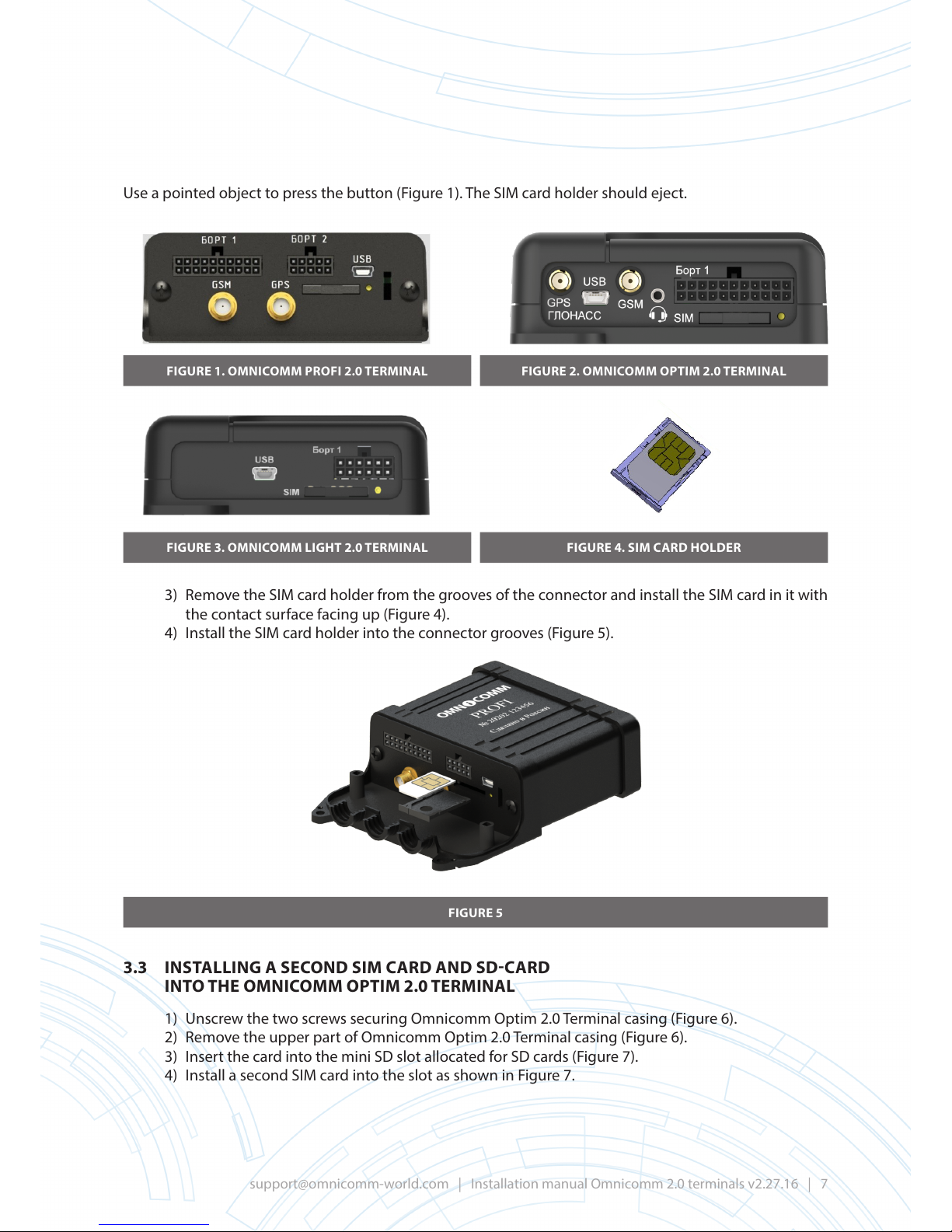
Use a pointed object to press the button (Figure 1). The SIM card holder should eject.
FIGURE 1. OMNICOMM PROFI 2.0 TERMINAL
FIGURE 3. OMNICOMM LIGHT 2.0 TERMINAL
FIGURE 2. OMNICOMM OPTIM 2.0 TERMINAL
FIGURE 4. SIM CARD HOLDER
3) Remove the SIM card holder from the grooves of the connector and install the SIM card in it with
the contact surface facing up (Figure 4).
4) Install the SIM card holder into the connector grooves (Figure 5).
FIGURE 5
3.3 INSTALLING A SECOND SIM CARD AND SD-CARD
INTO THE OMNICOMM OPTIM 2.0 TERMINAL
1) Unscrew the two screws securing Omnicomm Optim 2.0 Terminal casing (Figure 6).
2) Remove the upper part of Omnicomm Optim 2.0 Terminal casing (Figure 6).
3) Insert the card into the mini SD slot allocated for SD cards (Figure 7).
4) Install a second SIM card into the slot as shown in Figure 7.
Page 8
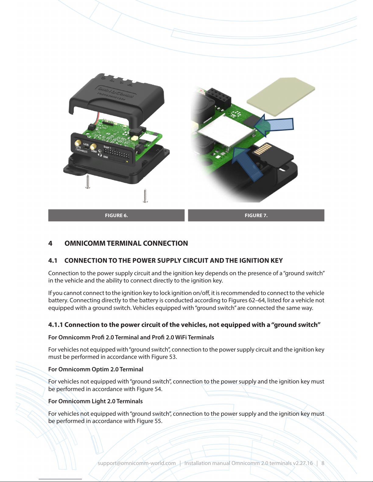
FIGURE 6. FIGURE 7.
4 OMNICOMM TERMINAL CONNECTION
4.1 CONNECTION TO THE POWER SUPPLY CIRCUIT AND THE IGNITION KEY
Connection to the power supply circuit and the ignition key depends on the presence of a “ground switch”
in the vehicle and the ability to connect directly to the ignition key.
If you cannot connect to the ignition key to lock ignition on/o, it is recommended to connect to the vehicle
battery. Connecting directly to the battery is conducted according to Figures 62–64, listed for a vehicle not
equipped with a ground switch. Vehicles equipped with “ground switch” are connected the same way.
4.1.1 Connection to the power circuit of the vehicles, not equipped with a “ground switch”
For Omnicomm Pro 2.0 Terminal and Pro 2.0 WiFi Terminals
For vehicles not equipped with “ground switch”, connection to the power supply circuit and the ignition key
must be performed in accordance with Figure 53.
For Omnicomm Optim 2.0 Terminal
For vehicles not equipped with “ground switch”, connection to the power supply and the ignition key must
be performed in accordance with Figure 54.
For Omnicomm Light 2.0 Terminals
For vehicles not equipped with “ground switch”, connection to the power supply and the ignition key must
be performed in accordance with Figure 55.
Page 9

4.1.2 Connecting to the power supply of the vehicle after “ground switch”
For Omnicomm Pro 2.0 and Pro 2.0 WiFi Terminals
For vehicles equipped with “ground switch”, connection must be performed in accordance with Figure 56.
For Omnicomm Optim 2.0 Terminals
For vehicles equipped with “ground switch”, connection must be performed in accordance with Figure 57.
For Omnicomm Light 2.0 Terminals
For vehicles equipped with “ground switch”, connection to the power supply and the ignition key must be
performed in accordance with Figure 58.
4.1.3 Connecting to the power supply of the vehicle before “ground switch”
For Omnicomm Pro 2.0, Pro 2.0 WiFi and Optim 2.0 Terminals
For vehicles equipped with “ground switch” when connecting before the “ground switch” to the battery
terminals, depending on the type of LLS sensor:
• When using LLS 20160 fuel level sensors, connection before “ground switch” must be performed
in accordance with Figures 59 and 60.
• For one LS 20230 fuel level sensor and BIS 20240 spark protection unit, connection to Omnicomm
Terminal must be performed via BR-15 galvanic isolator, in accordance with Figures 65 and 68.
• For two LS 20230 fuel level sensors and BIS 20240 spark protection unit, connection to Omnicomm
Pro 2.0 Terminal must be performed via BR-15 galvanic isolator, in accordance with Figure 67.
• For two LS 20230 fuel level sensors and one BIS 20240 spark protection unit and KTZ SplitterSplitter,
connection to Omnicomm Pro 2.0 Terminal must be performed via BR-15 galvanic isolator, in
accordance with Figure 66.
For Omnicomm Light 2.0 Terminals
For vehicles, equipped with “ground switch” when connecting before the “ground switch” to the battery
terminals, connection must be established in accordance with Figure 61.
4.2 CONNECTING THE SPEED SENSOR TO OMNICOMM PROFI 2.0
AND PROFI 2.0 WIFI TERMINALS
The connection is established based upon the type of speed sensor.
1) Connection to tachograph
Connection to tachograph must be established in accordance with the wiring connection diagram (Figure 77).
Connect only to the specied output terminals of the tachograph, which are chosen based upon the
contact diagram (as a rule, D3 or B7).
You can connect to the wires that lead from the output terminals of the tachograph to other on-board
devices.
2) Connecting to cable speedometer
Vehicles with cable speedometers are equipped with transmission boxes with a exible cable that can be
connected to the speedometer.
Page 10
For connecting to vehicles with cable speedometers, a transit speed sensor is used (VAZ vehicle 2110 10
imp/imp 6).
Determine which side of the exible cable, M18 thread is located on (i.e. on the gearbox/on the back side
of the speedometer).
Unscrew the exible cable and install transit speed sensor in the gap.
Connection of transit speed sensor must be performed according to Figure 79.
For some brands of URAL cars, installation of transit sensors may trigger failure of windshield wipers.
If this occurs, we recommend that you purchase a special adapter for “URAL” cars, manufactured by
Omnicomm, and install the sensor on the vehicle transmission.
3) Connection to the impulse speed sensor
Connection to impulse speed sensor is conducted in accordance with Figure 80.
4.3 CONNECTING TACHOMETER TO OMNICOMM PROFI 2.0,
PROFI 2.0 WIFI, AND OPTIM 2.0 TERMINALS
The location for connection of the tachometer must be a point in the electrical circuit of the vehicle in
which the frequency of the impulse signal is proportional to the engine speed.
The recommended circuit connection to tachometer is shown in Figure 81.
4.4 CONNECTION OF FUEL LEVEL SENSORS
4.4.1 Connecting LLS fuel level sensor to Omnicomm Pro 2.0
AND Pro 2.0 WiFi Terminal
Omnicomm Pro 2.0 Terminal supports connection of 1 to 6 LLS fuel level sensors or one LLS-AF fuel level
sensor with a frequency-modulated signal.
Connection of one LLS 30160/20160 fuel level sensor is conducted in accordance with Figure 69.
Connection of two or more LLS 30160/20160 fuel level sensors must be conducted in accordance with
Figure 71.
Connection of one LLS 20230 fuel level sensor and a BIS 20240 spark protection unit is conducted in
accordance with Figure 65.
Connection of two LLS 20230 fuel level sensors must be conducted in accordance with Figure 66 and 67,
depending on the number of BIS 20240 spark protection units utilised.
Connection of third and fourth LLS 20230 fuel level sensors must be conducted according to Figure 67.
Before connecting, perform capacity calibration test and set the following congurations for LLS fuel level
sensors (see “Datаsheet LLS 20160/LLS 20230”):
1) Enable the “Network” mode of operation.
2) Set the network addresses from 1 to 6.
LLS network addresses should be set strictly according to the procedure (for example, if you connect one
sensor, set the network address as “1”, for two sensors - set the network addresses as “1” and “2”, etc.).
Page 11

3) Set data transfer rate to 19200 bits/s.
Connection of LLS-AF fuel level sensor
Connection of LLS-AF 20310 fuel level sensor is conducted in accordance with Figure 72.
4.4.2 Connection of LLS fuel level sensors to Omnicomm Optim 2.0 Terminal
Omnicomm Optim 2.0 Terminal supports connection of 1 to 6 LLS fuel level sensors.
Connection of LLS 20160, LLS 30160 fuel level sensor is conducted in accordance with Figure 70.
Connection of LLS-AF fuel level sensor
Connection of LLS-AF 20310 fuel level sensor is conducted in accordance with Figure 72.
4.4.3 Connection of LLS fuel level sensor to Omnicomm Light 2.0 Terminal
Omnicomm Light 2.0 Terminal supports connection of one LLS fuel level sensors.
Connection of LLS 20160, LLS 30160 fuel level sensor is conducted in accordance with Figure 70.
Connection of LLS-AF fuel level sensor
Connection of LLS-AF 20310 fuel level sensor is conducted in accordance with Figure 73.
4.5 CONNECTION OF THE PANIC BUTTON
Connection of panic button proceeds according to the colours of the wires and the diagram for Omnicomm
Pro 2.0, Omnicomm Optim 2.0 and Omnicomm Light 2.0 Terminals (Figure 72).
Connect the black wire of the panic button with white-red wire connector for “SIDE 1” (for Omnicomm Pro
2.0 and Omnicomm Optim 2.0 Terminals) or with a black, or black and white, wire connector for “SIDE 1” (for
Omnicomm Light 2.0 Terminal).
4.6 CONNECTION OF VOICE COMMUNICATION EQUIPMENT
TO OMNICOMM PROFI 2.0, PROFI 2.0 WIFI AND OPTIM 2.0 TERMINALS
Connection of voice communication kit to Omnicomm Pro 2.0 and Pro 2.0 WiFi is conducted in accordance
with Figure 75.
Wiring of 2.5 mm mini-jack connector for connecting active speakers and microphone to the Omnicomm
Optim 2.0 Terminal is shown in Figure 76.
4.7 CONNECTION TO CAN BUS OF THE VEHICLE
Connection to CAN bus of the vehicle by using a wireless CAN reader (CAN-crocodile).
When utilising a CANcliQ reader (Figure 8) manufactured by Squarell, connection to the Omnicomm Pro
2.0 and Omnicomm Optim 2.0 Terminals is conducted in accordance with Figure 87.
Page 12
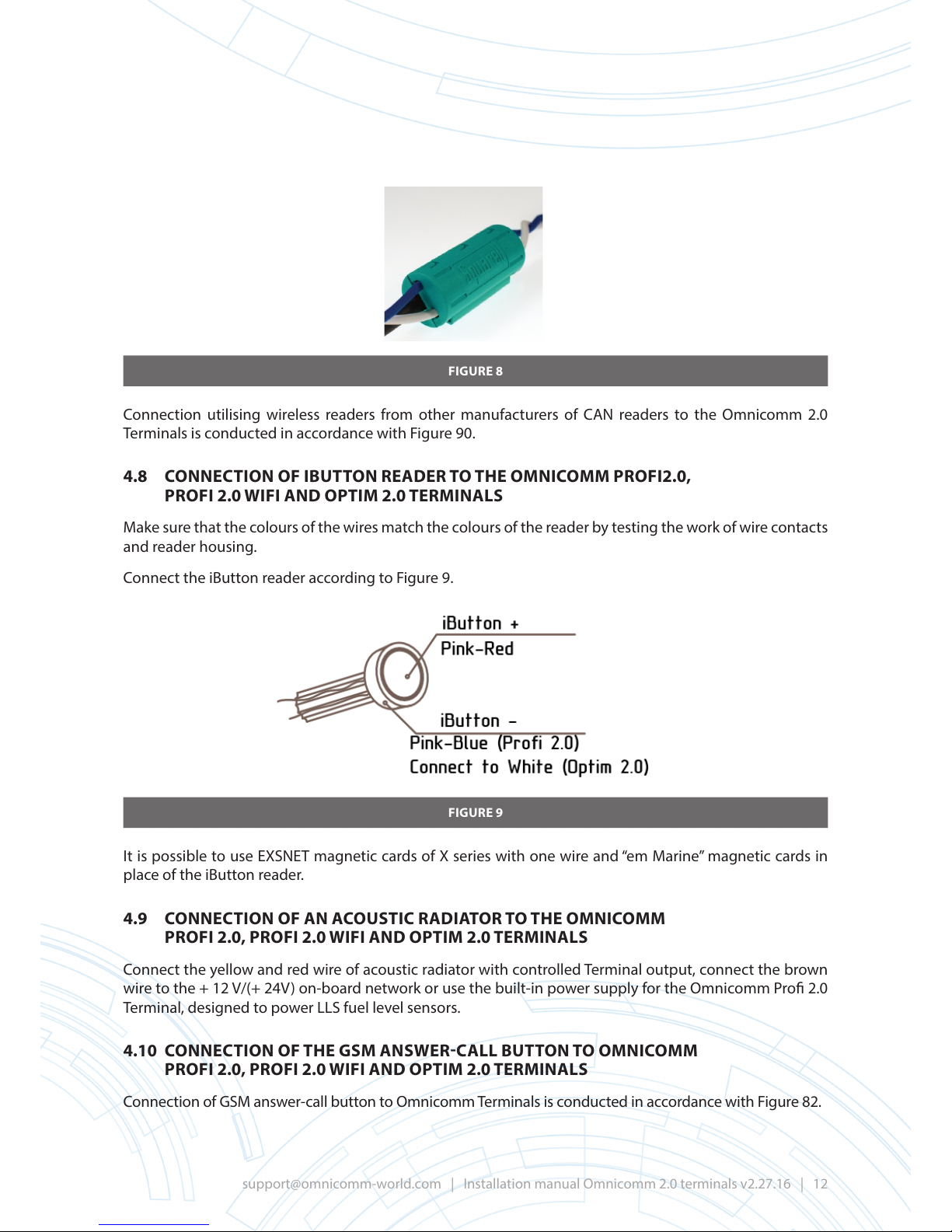
FIGURE 8
Connection utilising wireless readers from other manufacturers of CAN readers to the Omnicomm 2.0
Terminals is conducted in accordance with Figure 90.
4.8 CONNECTION OF IBUTTON READER TO THE OMNICOMM PROFI2.0,
PROFI 2.0 WIFI AND OPTIM 2.0 TERMINALS
Make sure that the colours of the wires match the colours of the reader by testing the work of wire contacts
and reader housing.
Connect the iButton reader according to Figure 9.
FIGURE 9
It is possible to use EXSNET magnetic cards of X series with one wire and “em Marine” magnetic cards in
place of the iButton reader.
4.9 CONNECTION OF AN ACOUSTIC RADIATOR TO THE OMNICOMM
PROFI 2.0, PROFI 2.0 WIFI AND OPTIM 2.0 TERMINALS
Connect the yellow and red wire of acoustic radiator with controlled Terminal output, connect the brown
wire to the + 12 V/(+ 24V) on-board network or use the built-in power supply for the Omnicomm Pro 2.0
Terminal, designed to power LLS fuel level sensors.
4.10 CONNECTION OF THE GSM ANSWER-CALL BUTTON TO OMNICOMM
PROFI 2.0, PROFI 2.0 WIFI AND OPTIM 2.0 TERMINALS
Connection of GSM answer-call button to Omnicomm Terminals is conducted in accordance with Figure 82.
Page 13

4.11 CONNECTION OF STANDARD
FUEL SENSOR OF THE VEHICLE
TO THE UNIVERSAL INPUT
Measure the voltage of the fuel sensor; if its power supply is of impulse type, the signal at the output of the
sensor will also be an impulse one with an amplitude of the voltage corresponding to the level of fuel in
the tank. To convert impulses at the sensor output to DC voltage, it is necessary to connect to the Terminal
via a PAM signal converter (Figure 82).
Measure the voltage from the fuel sensor with a full and empty tank. If the tank has a basic shape, removal
of intermediary points or the entire calibration table is not required.
Connect the output of the fuel sensor to the universal input No.1 of the Terminal. Select “Vehicle Sensor”
fuel sensor setting in Omnicomm Congurator and press the “Save Settings” button. After applying the
settings, the program will congure universal input No.1 into analog mode of operation with preset values
of the maximum and minimum measured quantity.
Install the empty-tank voltage value obtained from the sensor that corresponds to the minimum value of
the measured quantity, and with full tank - the voltage value, corresponding to the maximum value of the
measured quantity, then press “Save Settings”.
Check the display of the current values of the input voltage and the measured value in the settings of the
universal input.
Check the fuel sensor values displayed in the “Monitoring” tab to verify that they are in accordance with the
current value of the measured quantity.
When connecting the standard fuel sensor to the universal input of the Terminal, set operating mode
with the ignition o to “Collect data when shaking”. Otherwise, the fuel graph will be displayed
incorrectly.
After exporting the XML le and importing the vehicle in Omnicomm Online, in the vehicle prole,
the value of 4095 Cohn must be assigned to the value of the fuel volume in the tank in litres. If the fuel
tank has a complex shape, a calibration table of the tank must be created in Omnicomm Online.
4.12 CONFIGURE THE RECEIV
ED DATA REGARDING THE AMOUNT OF FUEL
IN THE TANK FROM THE CAN BUS OF THE VEHICLE
Connect and set the receiving parameters of the equipment of the vehicle from CAN bus J193 and congure
fuel sensor “CAN sensor”.
Check the fuel sensor display values in the “Monitoring” tab, the values of which must be between
0–4095.
When reading the fuel tank level with the CAN bus, set the operating mode of the Terminal when
the ignition is o to “Collect data when shaking”. Otherwise, the fuel graph will be displayed
incorrectly.
Page 14

After exporting the XML le and importing the vehicle in Omnicomm Online, in the vehicle prole, the value of
4095
Cohn must be assigned to the value of the fuel volume in the tank in litres. If the fuel tank has a complex
shape, a calibration table of the tank must be created in Omnicomm Online.
4.13 CONNECTION OF THE TEMPERATURE SENSORS 1WIRE TO OMNICOMM
PROFI 2.0, PROFI 2.0 WIFI AND OPTIM 2.0 TERMINALS
Connection of the temperature
sensor to the Omnicomm Pro 2.0, Optim 2.0 Terminals is conducted in
accordance with Figure 84. Omnicomm Pro 2.0 and Optim 2.0 Terminals support connection of up to 10
temperature sensors on a single-wire (hub) power circuit. You may simultaneously use the interface 1Wire
to connect temperature sensors and the iButton reader. The maximum line length of 1wire is 100 m.
4.14 CONNECTING ADDITIONAL EQUIPMENT TO THE UNIVERSAL INPUTS
Omnicomm Pro 2.0 and Pro 2.0 WiFi Terminals support connection of up to six devices as optional
equipment.
Omnicomm Optim 2.0 Terminals support connection of up to four devices as optional equipment.
Omnicomm Light 2.0 Terminals support connection of two devices as optional equipment.
To control additional equipment when connecting to a universal input, it is recommended that you use the
available signals, for example, from the control elements, or install additional sensors (see “UM Omnicomm
2.0 Terminal”).
For third-party sensors, it is necessary to establish connection according to user manual of the sensor.
4.14.1 Connection of sensors with analog output
Sensor types:
• with standardised current output
• with standardised voltage output
• LLS-AF 20310 fuel level sensor
Measured values: temperature, pressure, humidity, etc.
Connection of the sensor with standardised current output is conducted in accordance with Figure 94.
This wiring diagram only applies to vehicles with on-board network voltage of 24 V.
For sensors that can be powered by a voltage of 10 V, connect the sensor to the standardised voltage
output according to Figure 93.
Do not connect: standard engine temperature sensors, high-voltage sensors, non-linear signal sensors, and
power supply sources without shunt resistance.
Connection of DT14V temperature sensor is conducted in accordance with Figure 92.
4.14.2 Connection of sensors with potential or impulse output
Possible types of sensors include: contact and proximity discrete sensors
Connection of proximity sensors (capacitive, inductive, optical or magnetic type) and “open collect”
sensors with N-P-N outputs is conducted in accordance with Figure 96.
Page 15

Connection
of contact sensor is conducted in accordance with Figure 95. Regular hardware control
elements (i.e. actuation buttons/end switches/sensors that are triggered by increased pressure or
temperature, etc.) or additionally installed sensors may act as contact sensors. It is recommended that
you rst search for an opportunity to connect to a standard device and only install an additional sensor
in the absence of such.
4.15 CONNECTING ADDITIONAL EQUIPMENT TO CONTROLLED OUTPUTS
Connection of additional equipment to controlled outputs 1 and 2 of the Omnicomm Pro 2.0 and
Omnicomm Optim 2.0 Terminals is conducted in accordance with Figure 77.
Connection of additional equipment to controlled output 1 of the Omnicomm Light 2.0 Terminal is
conducted in accordance with Figure 77.
Current consumption of additional equipment must be no more than 300 mA.
Omnicomm 2.0 Terminals (excluding Smart 2.0) provide for up to three operation rules for every controlled
output.
The rules are set per event or per combination of events and states.
Open the tab “Outputs” in the screen “Settings”:
“Rule priority” - set the rule priority. When a few rules trigger, the one with the highest priority is fullled.
Select “Events”:
Geofence entry;
Geofence exit.
Select “States”:
Ignition on;
Ignition o;
GPS;
No GPS;
In geofence
• Excess of the indicated speed threshold;
In the section “Output operation mode”:
Number of cycles “closed-open” – specify the number of output on/os.
Possible options:
permanently – the output is permanently on (accessible only for states);
from 1 to 9 (relevant for events only, because for the states, if the condition is held, the cycles will be
repeated innitely).
Selecting the number of cycles, specify:
“Delay before closing, s” – specify the time before the output is on. Possible values: from 0.1 to 9.9 s.
Page 16
“Closing duration, s” – specify the time during which the output must be switched on. Possible values: from
0.1 to 9.9 s.
“Opening duration, s” – specify the time before a recurrent output switching on. Possible values: from 0.0 to 29.9 s.
Example 1. The following values are set:
State – “In geofence”,
Number of cycles “closed-open” - 5.
If the VH is inside the geofence, the output will go on-o 5 times. Switching the output on-o (5 times) will
be repeated until the VH leaves the geofence.
Example 2. The following values are set:
State – “Out of geofences”, “GPS”,
Number of cycles “closed-open” – “Permanently”.
If the VH
is outside the geofence and GPS-module data are valid, the output will be on until the VH enters
the geofence or GPS data terminate.
4.16 GEOFENCING
Omnicomm 2.0 Terminals (excluding Smart 2.0) provide for geofencing to switch on controlled outputs.
Open the tab “Geofences” in the screen “Settings”:
“Number of points to conrm location inside/outside geofence” – specify the number of sequentially
determined VH coordinates required to track the VH location inside or outside the geofence. The period of
coordinate determining is 1 sec. Possible values: from 1 to 10.
To add a geofence, press the button “Import” and select the xml-le with geofence settings.
Maximum number of geofences is 6. Maximum number of angular points is 24.
4.17 CONNECTING ADDITIONAL EQUIPMENT TO RS-485 AND RS-232 INTERFACES
Connection of additional equipment (CAN-Log, PP-01 passenger ow sensors, DV-1 driver display,
JPEG camera, receiving data from information bus J1708 of the vehicle, reception and transmission of
navigational information in accordance with NMEA standard) is established to the RS-485 and RS-232
interfaces. If necessary, it is recommended that you use RS-232/RS-485 converter.
Connection of optional equipment, such as the RS-232 interface to the Omnicomm Optim 2.0, Pro 2.0
and Pro 2.0 WiFi Terminals, is conducted in accordance with Figure 85, when utilising the RS-232/RS-485
converter, Figure 86.
Connection of additional equipment, such as the RS-485 interface to the Omnicomm Optim 2.0, Pro 2.0
and Pro 2.0 WiFi Terminals, is conducted in accordance with Figure 88, and when utilising the RS-232/RS-
485 converter, Figure 89.
4.18 FUSE INSTALLATION
Fuses are designed to protect the on-board network of the vehicle from electrical system short-circuits in
cases of breakdown of product wiring.
Connect the product wires to the fuse holders and in close proximity to the signal sources (Figures 53–55).
Page 17
4.
19 REQUIREMENTS FOR THE LAYING OF CONNECTION CABLES
4.19.1 General guidelines for connecting cables
Remove 8–10 mm of the insulation from the ends of the wires in order to strip the wires.
Twist each end of the wire to avoid the separation of wire bres.
Insert the ends of the wires into the coupling sleeve that is supplied with the product or purchased
separately.
Crimp the coupling sleeve with pliers or a special tool.
Cable connector pin assignments are provided in Appendix G.
4.19.2 Guidelines for laying cables
During installation, you must use included cables manufactured by Omnicomm that are supplied with the
product or purchased separately.
The cable must not be placed near heated parts of the machinery or components of the vehicle that may
melt the insulation of the wiring.
The cable must not be placed near any moving parts of the vehicle.
4.20 CONNECT THE CABLES TO THE CONNECTORS
OF THE OMNICOMMPROFI 2.0 AND PROFI 2.0 WIFI TERMINAL
Connection of the cables to the connectors of the Omnicomm Pro 2.0 Terminal can be conducted by two
methods: by utilising a goer or supplied rubber clamps. When connecting cables with goer, protection
level of IP51 is guaranteed; when using rubber cable outputs - IP41 protection level.
4.2
0.1 Connection of cables to the connectors of Omnicomm Pro 2.0
and Pro 2.0 WiFi Terminals using goers
Cut three pieces of goer to the required length. Goers are not included and are sold separately.
Place the wires of the cable, connected to “SIDE 2”, into one piece of goer.
Place at rst the GSM antenna cable into another piece of goer, and then 10 wires of the cable, attached
to “SIDE 1” connectors.
At rst, place the GPS antenna cable into the third piece of goer, and then the remaining 10 wires of the
cable, attached to “SIDE 1” connectors.
Place the goer in the allocated slots and lock it the clamps (Figure 10 and 11).
Page 18
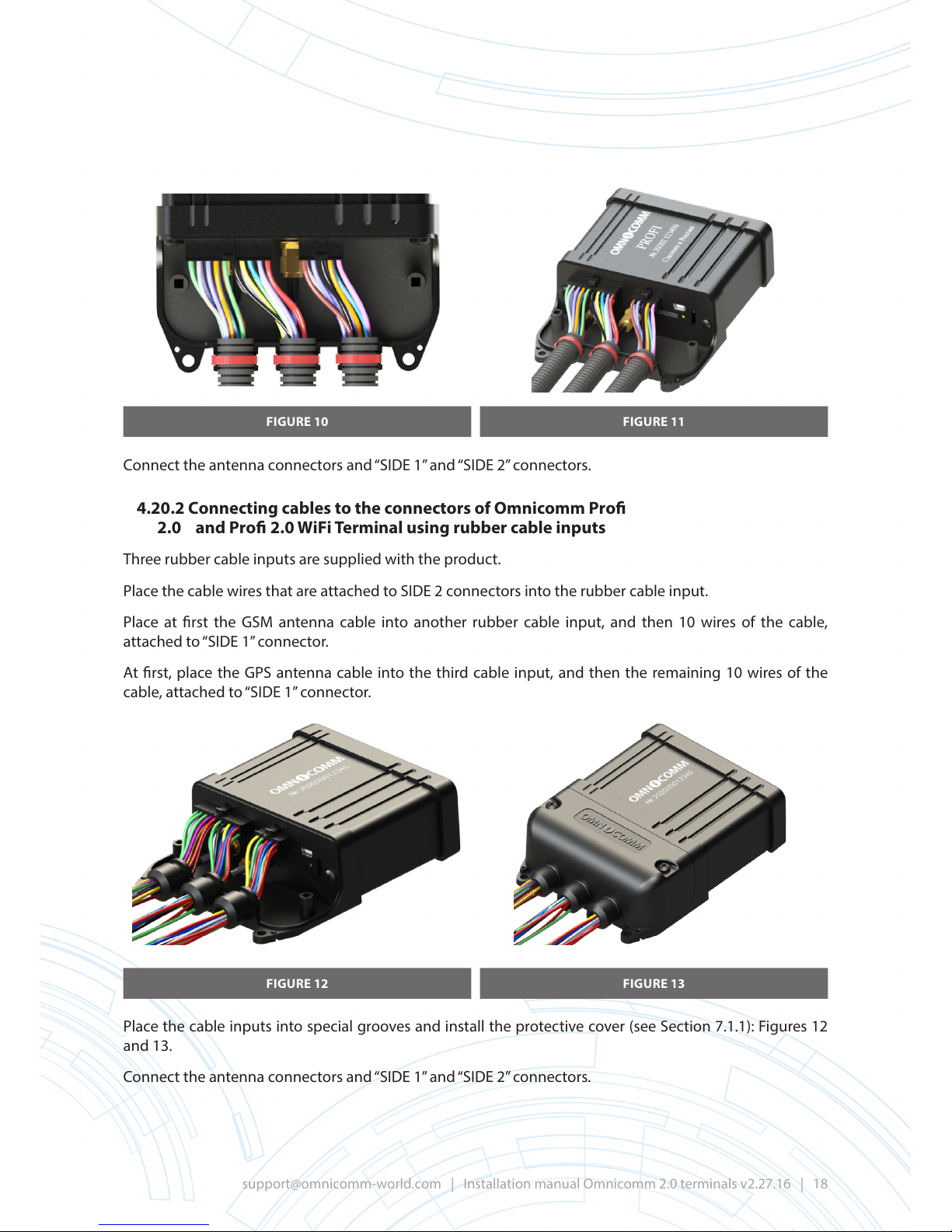
FIGURE 10 FIGURE 11
Connect the antenna connectors and “SIDE 1” and
“SIDE 2” connectors.
4.20.2 Connecting cables to the connectors of Omnicomm Pro
2.0 and Pro 2.0 WiFi Terminal using rubber cable inputs
Three rubber cable inputs are supplied with the product.
Place the cable wires that are attached to SIDE 2 connectors into the rubber cable input.
Place at rst the GSM antenna cable into another rubber cable input, and then 10 wires of the cable,
attached to “SIDE 1” connector.
At rst, place the GPS antenna cable into the third cable input, and then the remaining 10 wires of the
cable, attached to “SIDE 1” connector.
FIGURE 12 FIGURE 13
Place the cable inputs into special grooves and install the protective cover (see Section 7.1.1): Figures 12
and 13.
Connect the antenna connectors and “SIDE 1” and “SIDE 2” connectors.
Page 19

4.2
1 CONNECT THE CABLES TO THE CONNECTORS OF OMNICOMM OPTIM 2.0 TERMINAL
Connect the antenna connectors and “SIDE 1” connectors (Figure 14).
FIGURE 14
4.2
2 CONNECT THE CABLES TO THE CONNECTORS OF OMNICOMM LIGHT 2.0 TERMINAL
Connect the antenna connectors and “SIDE 1” connectors (Figure 15).
FIGURE 15
5 REQUIRED OPERATIONAL SETTINGS FOR OMNICOMM2.0 TERMINALS
5.1 TERMINAL CONFIGURATION USING OMNICOMM CONFIGURATOR
Connect the PC to the Omnicomm Terminal in accordance With Figure 91. Power supply to the Omnicomm
Pro 2.0 and Pro 2.0 WiFi Terminal is conducted via the USB interface. To power the Omnicomm Optim 2.0
Terminal, you must be connected to the vehicle on-board network or to power supply unit.
The Omnicomm Terminal conguration settings are conducted in accordance with the Omnicomm
Congurator User Manual.
Page 20
6 INSTALLATION AND DISMANTLING
6.1 INSTALLATION OF THE OMNICOMM TERMINAL
1) The Omnicomm Terminal should be mounted inside the vehicle cabin or in specially designed
boxes of electrical equipment on the vehicle, protected from precipitation.
2) Omnicomm Terminal must be installed on a smooth surface. It is possible to install it on both
vertical and horizontal surfaces.
3) In order to maximise the eectiveness of the built-in GSM and GLONASS / GPS antennas of the
Omnicomm Light 2.0 Terminal, it is recommended to x the position of the Terminal such that it is
as close as possible to horizontal, in a location with an eective radio span of the sky.
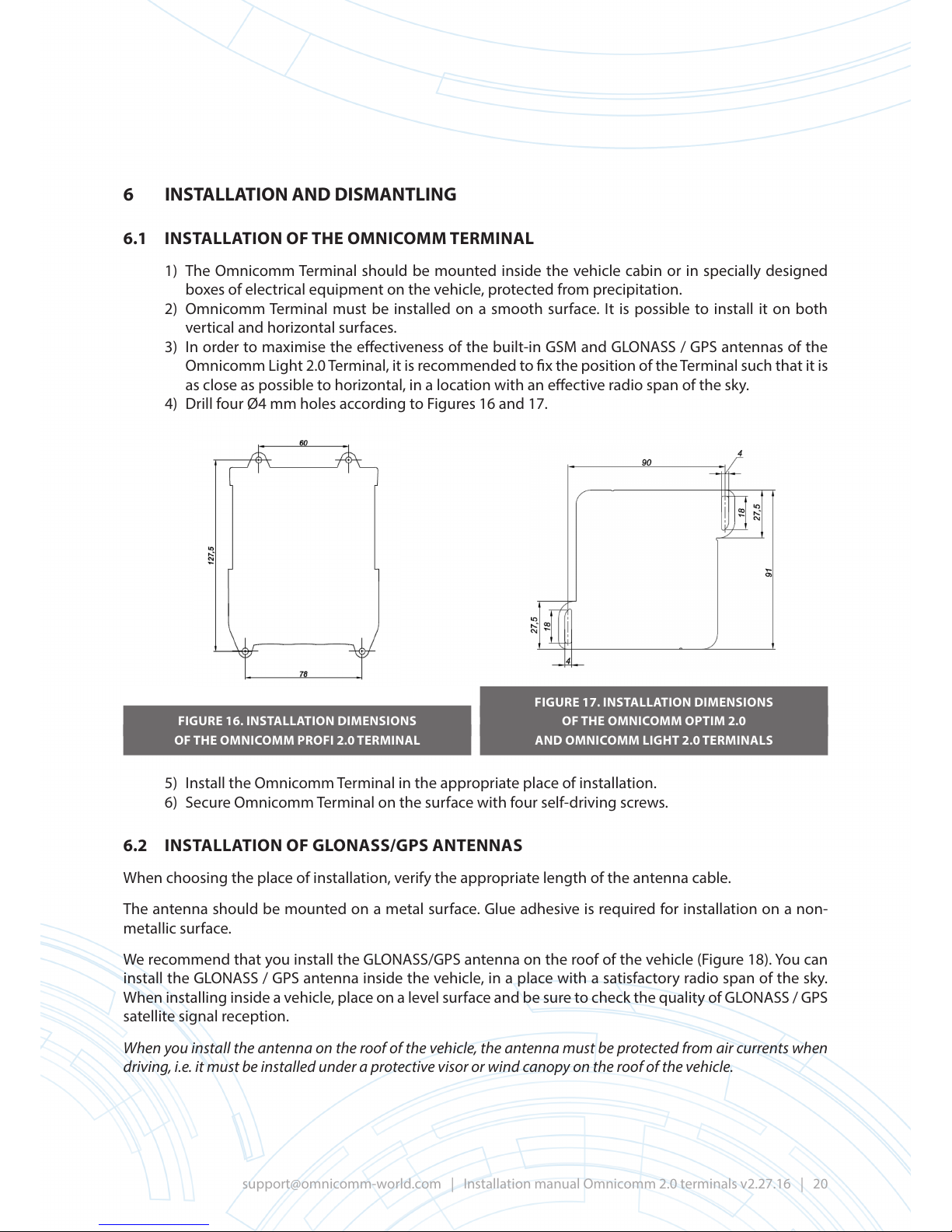
4) Drill four Ø4 mm holes according to Figures 16 and 17.
FIGURE 16. INSTALLATION DIMENSIONS
OF THE OMNICOMM PROFI 2.0 TERMINAL
FIGURE 17. INSTALLATION DIMENSIONS
OF THE OMNICOMM OPTIM 2.0
AND OMNICOMM LIGHT 2.0 TERMINALS
5) Install the Omnicomm Terminal in the appropriate place of installation.
6) Secure Omnicomm Terminal on the surface with four self-driving screws.
6.2 INSTALLATION OF GLONASS/GPS ANTENNAS
When choosing the place of installation, verify the appropriate length of the antenna cable.
The antenna should be mounted on a metal surface. Glue adhesive is required for installation on a non-
metallic surface.
We recommend that you install the GLONASS/GPS antenna on the roof of the vehicle (Figure 18). You can
install the GLONASS / GPS antenna inside the vehicle, in a place with a satisfactory radio span of the sky.
When installing inside a vehicle, place on a level surface and be sure to check the quality of GLONASS / GPS
satellite signal reception.
When you install the antenna on the roof of the vehicle, the antenna must be protected from air currents when
driving, i.e. it must be installed under a protective visor or wind canopy on the roof of the vehicle.
Page 21
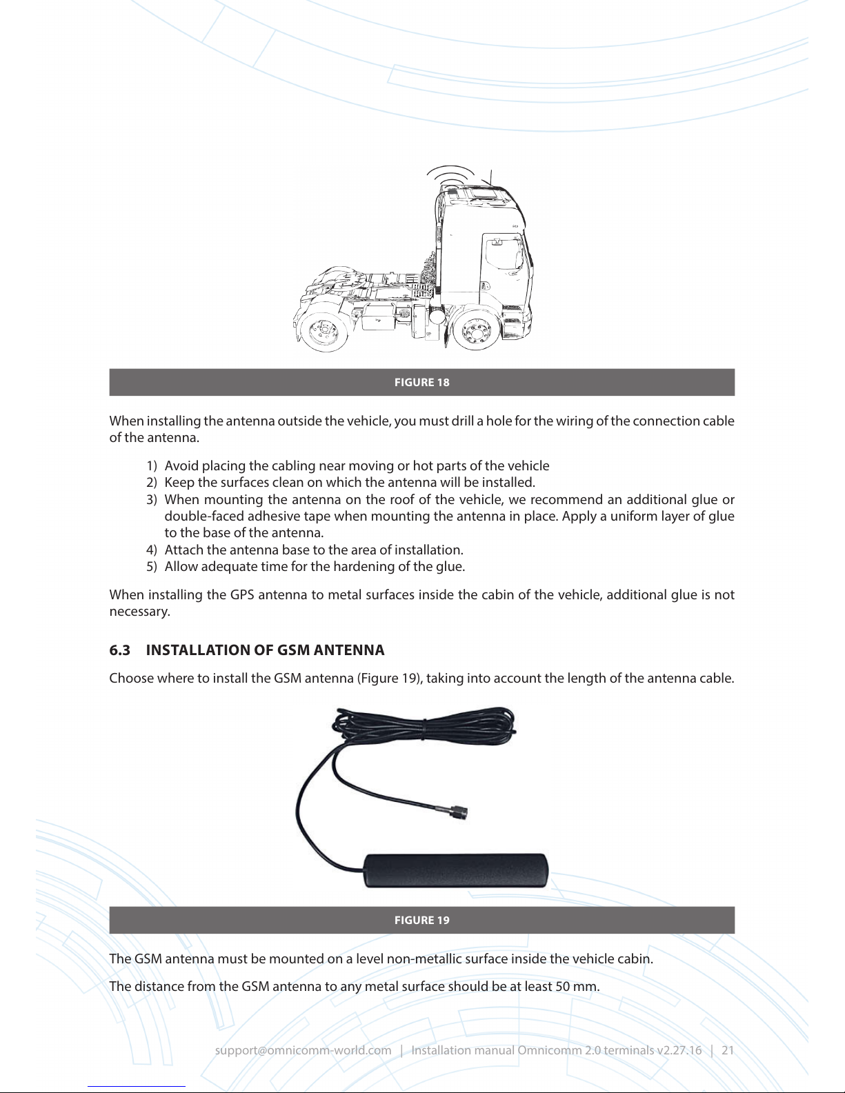
FIGURE 18
When installing the antenna outside the vehicle, you must drill a hole for the wiring of the connection cable
of the antenna.
1) Avoid placing the cabling near moving or hot parts of the vehicle
2) Keep the surfaces clean on which the antenna will be installed.
3) When mounting the antenna on the roof of the vehicle, we recommend an additional glue or
double-faced adhesive tape when mounting the antenna in place. Apply a uniform layer of glue
to the base of the antenna.
4) Attach the antenna base to the area of installation.
5) Allow adequate time for the hardening of the glue.
When installing the GPS antenna to metal surfaces inside the cabin of the vehicle, additional glue is not
necessary.
6.3 INSTALLATION OF GSM ANTENNA
Choose where to install the GSM antenna (Figure 19), taking into account the length of the antenna cable.
FIGURE 19
The GSM antenna must be mounted on a level non-metallic surface inside the vehicle cabin.
The distance from the GSM antenna to any metal surface should be at least 50 mm.
Page 22

Recommended installation location for GSM antenna include: vehicle windscreen or inside the plastic front
panel of the vehicle.
Clean the surface of installation area of grease.
Remove the protective lm from the double-faced adhesive tape on the surface of the GSM antenna.
Attach the adhesive side of the GSM antenna to the installation site.
Allow for the necessary time for the hardening of glue around the GSM antenna.
6.4 INSTALLATION OF WIFI ANTENNA FOR OMNICOMM PROFI 2.0 WIFI TERMINAL
Select the place of installation for the WiFi antenna taking into consideration the antenna cable length.
The WiFi antenna should be mounted inside the vehicle cabin on a smooth, at, non-metallic surface.
The distance from the WiFi antenna to any metal surface must be at least 50 mm.
Recommended installation location for WiFi antenna include: vehicle windscreen or inside the plastic front
panel of the vehicle.
Clean the surface of installation area of grease.
Remove the protective lm from the double-faced adhesive tape on the surface of the WiFi antenna.
Attach the adhesive side of the WiFi antenna to the installation site.
Allow for the necessary time for the hardening of glue around the WiFi antenna.
6.5 PANIC BUT TON INSTALLATI ON
The panic button should be installed at the front panel of the vehicle, or in any convenient location within
the vehicle cabin.
At the installation site, drill a Ø12 mm hole.
Set the panic button in the prepared hole, securing it with a ring and a locking washer.
It is permitted to install a third-party panic button (without locking an actuation position).
6.6 INSTALLATION OF BACK-UP BATTERY
The backup battery must be installed in the cabin of the vehicle. It is recommended that you install it in a
hidden location, under the dashboard.
Make clamps from the perforated metal tape that was supplied with the backup battery cable.
Secure the batteries with clamps under the dashboard using self-driving screws or bolts.
6.7 INSTALLING VOICE COMMUNICATION KIT FOR OMNICOMM PROFI 2.0
AND PROFI 2.0 WIFI TERMINALS
1) On installation site, drill two Ø 2.5 mm holes (Figure 20).
2) Drill the 30 x 12 mm rectangular opening using a cutting tool or drill (Figure 20).
3) Install the adapter of push-to-talk switch into the prepared hole (Figure 21).
Page 23
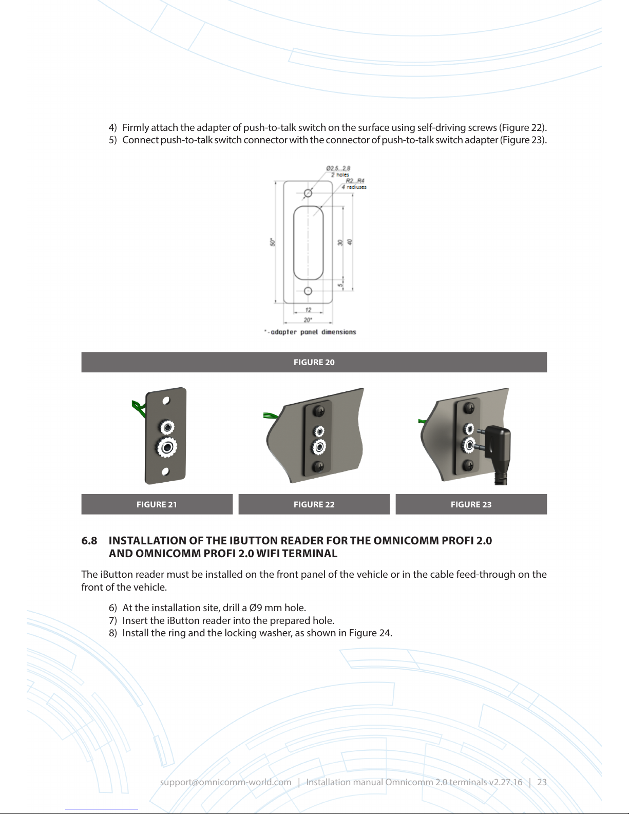
4) Firmly attach the adapter of push-to-talk switch on the sur face using self-driving screws (Figure 22).
5) Connect push-to-talk switch connector with the connector of push-to-talk switch adapter (Figure 23).
FIGURE 20
FIGURE 21 FIGURE 22 FIGURE 23
6.8 INSTALLATION OF THE IBUTTON READER FOR THE OMNICOMM PROFI 2.0
AND OMNICOMM PROFI 2.0 WIFI TERMINAL
The iButton reader must be installed on the front panel of the vehicle or in the cable feed-through on the
front of the vehicle.
6) At the installation site, drill a Ø9 mm hole.
7) Insert the iButton reader into the prepared hole.
8) Install the ring and the locking washer, as shown in Figure 24.
Page 24
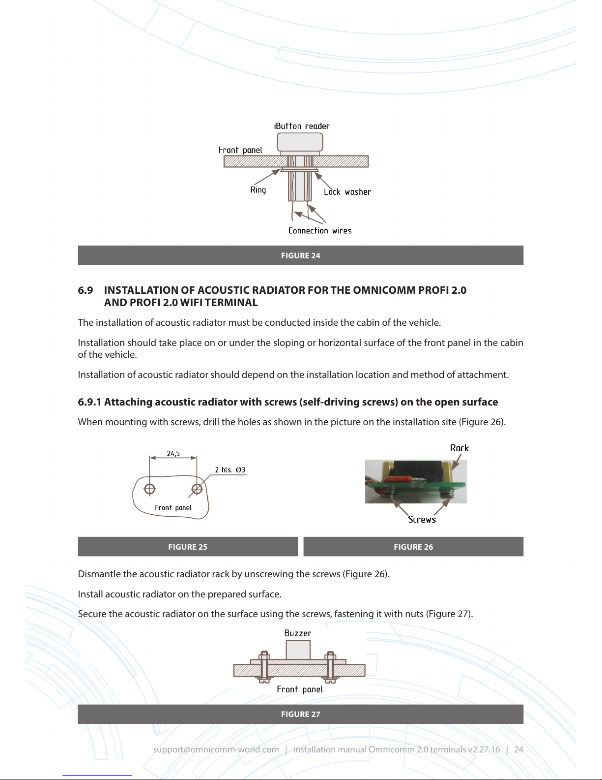
FIGURE 24
6.9 INSTALLATION OF ACOUSTIC RADIATOR FOR THE OMNICOMM PROFI 2.0
AND PROFI 2.0 WIFI TERMINAL
The installation of acoustic radiator must be conducted inside the cabin of the vehicle.
Installation should take place on or under the sloping or horizontal surface of the front panel in the cabin
of the vehicle.
Installation of acoustic radiator should depend on the installation location and method of attachment.
6.9.1 Attaching acoustic radiator with screws (self-driving screws) on the open surface
When mounting with screws, drill the holes as shown in the picture on the installation site (Figure 26).
FIGURE 25 FIGURE 26
Dismantle the acoustic radiator rack by unscrewing the screws (Figure 26).
Install acoustic radiator on the prepared surface.
Secure the acoustic radiator on the surface using the screws, fastening it with nuts (Figure 27).
FIGURE 27
Page 25
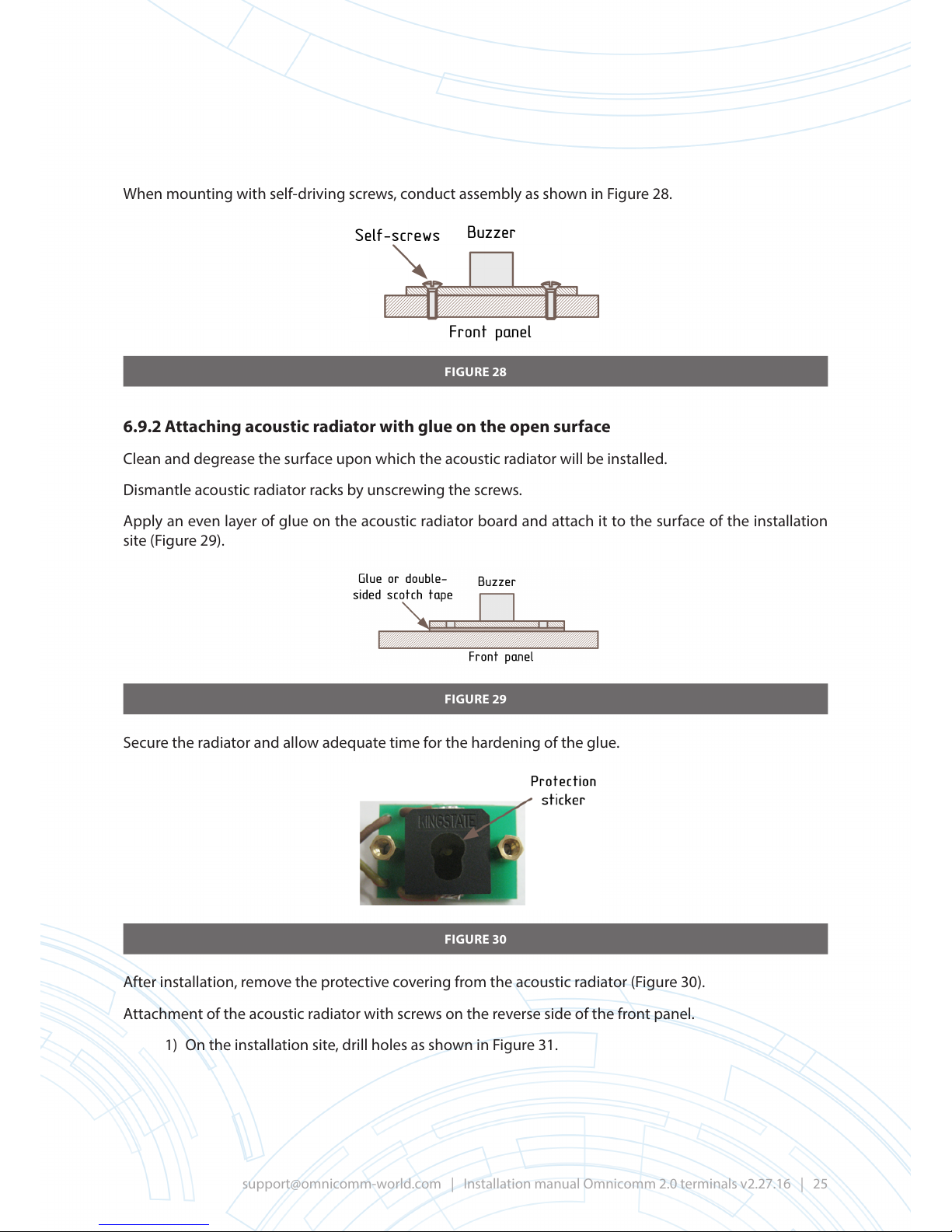
When mounting with self-driving screws, conduct assembly as shown in Figure 28.
FIGURE 28
6.9.2 Attaching acoustic radiator with glue on the open surface
Clean and degrease the surface upon which the acoustic radiator will be installed.
Dismantle acoustic radiator racks by unscrewing the screws.
Apply an even layer of glue on the acoustic radiator board and attach it to the surface of the installation
site (Figure 29).
FIGURE 29
Secure the radiator and allow adequate time for the hardening of the glue.
FIGURE 30
After installation, remove the protective covering from the acoustic radiator (Figure 30).
Attachment of the acoustic radiator with screws on the reverse side of the front panel.
1) On the installation site, drill holes as shown in Figure 31.
Page 26
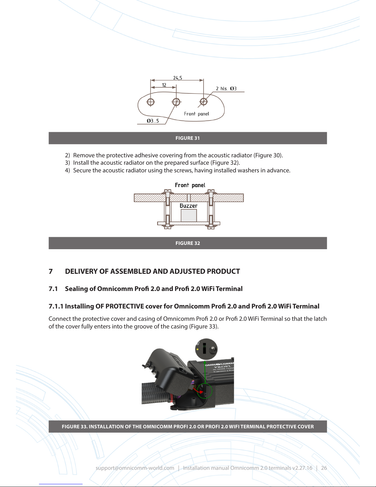
FIGURE 31
2) Remove the protective adhesive covering from the acoustic radiator (Figure 30).
3) Install the acoustic radiator on the prepared surface (Figure 32).
4) Secure the acoustic radiator using the screws, having installed washers in advance.
FIGURE 32
7 DELIVERY OF ASSEMBLED AND ADJUSTED PRODUCT
7.1 Sealing of Omnicomm Pro 2.0 and Pro 2.0 WiFi Terminal
7.1.1 Installing OF PROTECTIVE cover for Omnicomm Pro 2.0 and Pro 2.0 WiFi Terminal
Connect the protective cover and casing of Omnicomm Pro 2.0 or Pro 2.0 WiFi Terminal so that the latch
of the cover fully enters into the groove of the casing (Figure 33).
FIGURE 33. INSTALLATION OF THE OMNICOMM PROFI 2.0 OR PROFI 2.0 WIFI TERMINAL PROTECTIVE COVER
Page 27
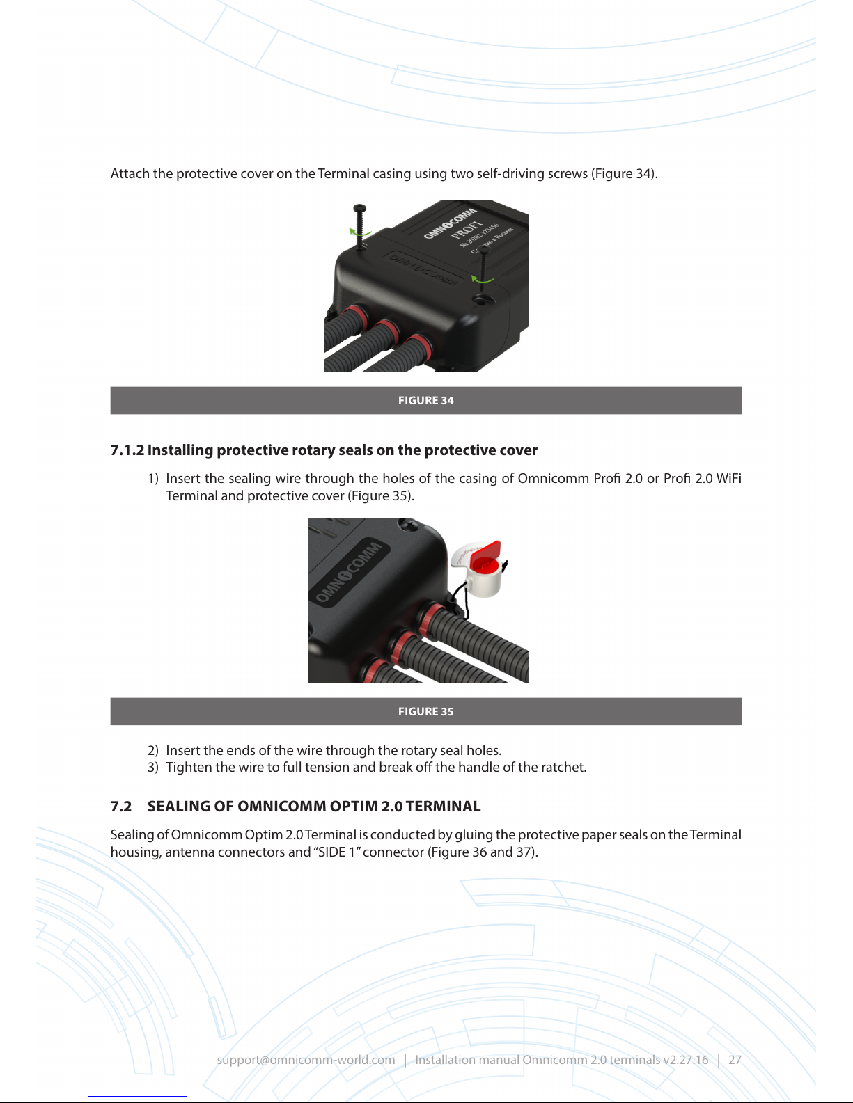
Attach the protective cover on the Terminal casing using two self-driving screws (Figure 34).
FIGURE 34
7.1.2 Installing protective rotary seals on the protective cover
1) Insert the sealing wire through the holes of the casing of Omnicomm Pro 2.0 or Pro 2.0 WiFi
Terminal and protective cover (Figure 35).
FIGURE 35
2) Insert the ends of the wire through the rotary seal holes.
3) Tighten the wire to full tension and break o the handle of the ratchet.
7.2 SEALING OF OMNICOMM OPTIM 2.0 TERMINAL
Sealing of Omnicomm Optim 2.0 Terminal is conducted by gluing the protective paper seals on the Terminal
housing, antenna connectors and “SIDE 1” connector (Figure 36 and 37).
Page 28
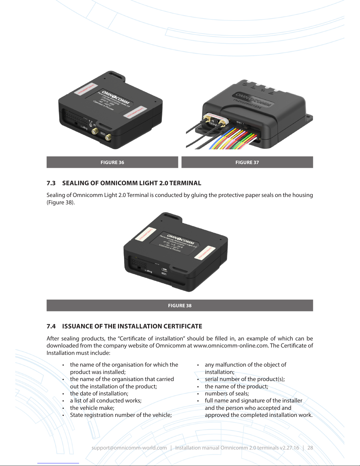
FIGURE 36 FIGURE 37
7.3 SEALING OF OMNICOMM LIGHT 2.0 TERMINAL
Sealing of Omnicomm Light 2.0 Terminal is conducted by gluing the protective paper seals on the housing
(Figure 38).
FIGURE 38
7.4 ISSUANCE OF THE INSTALLATION CERTIFICATE
After sealing products, the “Certicate of installation” should be lled in, an example of which can be
downloaded from the company website of Omnicomm at www.omnicomm-online.com. The Certicate of
Installation must include:
• the name of the organisation for which the
product was installed;
• the name of the organisation that carried
out the installation of the product;
• the date of installation;
• a list of all conducted works;
• the vehicle make;
• State registration number of the vehicle;
• any malfunction of the object of
installation;
• serial number of the product(s);
• the name of the product;
• numbers of seals;
• full name and signature of the installer
and the person who accepted and
approved the completed installation work.
Page 29
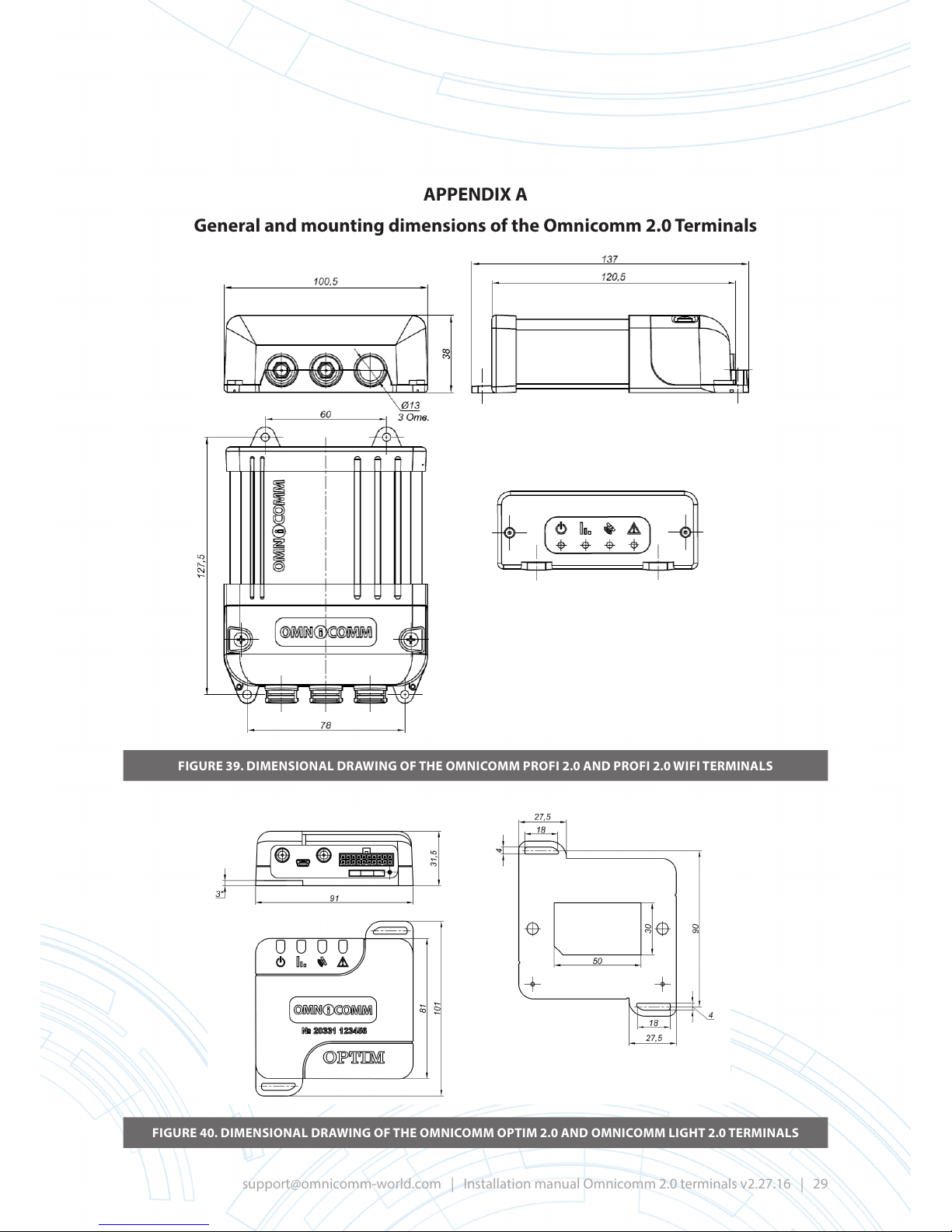
APPENDIX A
General and mounting dimensions of the Omnicomm2.0 Terminals
FIGURE 39. DIMENSIONAL DRAWING OF THE OMNICOMM PROFI 2.0 AND PROFI 2.0 WIFI TERMINALS
FIGURE 40. DIMENSIONAL DRAWING OF THE OMNICOMM OPTIM 2.0 AND OMNICOMM LIGHT 2.0 TERMINALS
Page 30
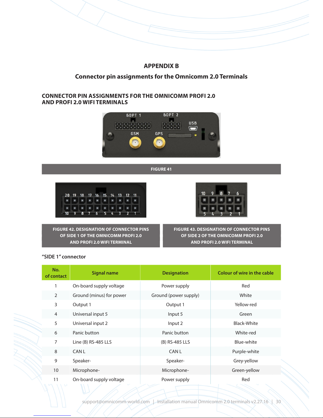
APPENDIX B
Connector pin assignments for the Omnicomm 2.0 Terminals
CONNECTOR PIN ASSIGNMENTS FOR THE OMNICOMM PROFI 2.0
AND PROFI 2.0 WIFI TERMINALS
FIGURE 41
FIGURE 42. DESIGNATION OF CONNECTOR PINS
OF SIDE 1 OF THE OMNICOMM PROFI 2.0
AND PROFI 2.0 WIFI TERMINAL
FIGURE 43. DESIGNATION OF CONNECTOR PINS
OF SIDE 2 OF THE OMNICOMM PROFI 2.0
AND PROFI 2.0 WIFI TERMINAL
“SIDE 1” connector
No.
of contact
Signal name Designation Colour of wire in the cable
1 On-board supply voltage Power supply Red
2 Ground (minus) for power Ground (power supply) White
3 Output 1 Output 1 Yellow-red
4 Universal input 5 Input 5 Green
5 Universal input 2 Input 2 Black-White
6 Panic button Panic button White-red
7 Line (B) RS-485 LLS (B) RS-485 LLS Blue-white
8 CAN L CAN L Purple-white
9 Speaker- Speaker- Grey-yellow
10 Microphone- Microphone- Green-yellow
11 On-board supply voltage Power supply Red
Page 31
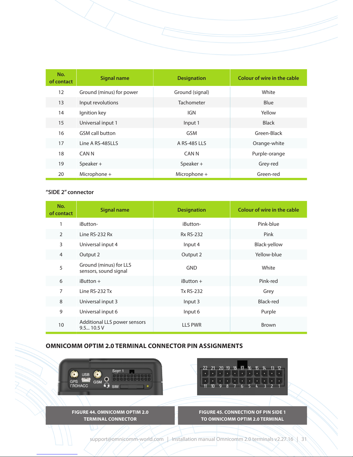
No.
of contact
Signal name Designation Colour of wire in the cable
12 Ground (minus) for power Ground (signal) White
13 Input revolutions Tachometer Blue
14 Ignition key IGN Yellow
15 Universal input 1 Input 1 Black
16 GSM call button GSM Green-Black
17 Line A RS-485LLS A RS-485 LLS Orange-white
18 CAN N CAN N Purple-orange
19 Speaker + Speaker + Grey-red
20 Microphone + Microphone + Green-red
“SIDE 2” connector
No.
of contact
Signal name Designation Colour of wire in the cable
1 iButton- iButton- Pink-blue
2 Line RS-232 Rx Rx RS-232 Pink
3 Universal input 4 Input 4 Black-yellow
4 Output 2 Output 2 Yellow-blue
5
Ground (minus) for LLS
sensors, sound signal
GND White
6 iButton + iButton + Pink-red
7 Line RS-232 Tx Tx RS-232 Grey
8 Universal input 3 Input 3 Black-red
9 Universal input 6 Input 6 Purple
10
Additional LLS power sensors
9.5... 10.5 V
LLS PWR Brown
OMNICOMM OPTIM 2.0 TERMINAL CONNECTOR PIN ASSIGNMENTS
FIGURE 44. OMNICOMM OPTIM 2.0
TERMINAL CONNECTOR
FIGURE 45. CONNECTION OF PIN SIDE 1
TO OMNICOMM OPTIM 2.0 TERMINAL
Page 32
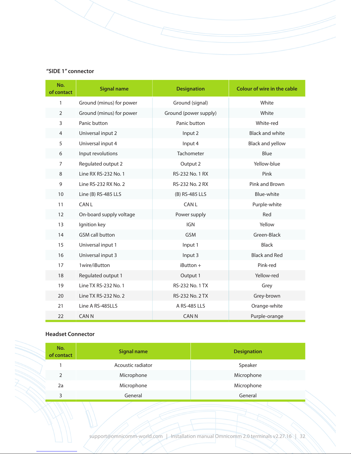
“SIDE 1” connector
No.
of contact
Signal name Designation Colour of wire in the cable
1 Ground (minus) for power Ground (signal) White
2 Ground (minus) for power Ground (power supply) White
3 Panic button Panic button White-red
4 Universal input 2 Input 2 Black and white
5 Universal input 4 Input 4 Black and yellow
6 Input revolutions Tachometer Blue
7 Regulated output 2 Output 2 Yellow-blue
8 Line RX RS-232 No. 1 RS-232 No. 1 RX Pink
9 Line RS-232 RX No. 2 RS-232 No. 2 RX Pink and Brown
10 Line (B) RS-485 LLS (B) RS-485 LLS Blue-white
11 CAN L CAN L Purple-white
12 On-board supply voltage Power supply Red
13 Ignition key IGN Yellow
14 GSM call button GSM Green-Black
15 Universal input 1 Input 1 Black
16 Universal input 3 Input 3 Black and Red
17 1wire/iButton iButton + Pink-red
18 Regulated output 1 Output 1 Yellow-red
19 Line TX RS-232 No. 1 RS-232 No. 1 TX Grey
20 Line TX RS-232 No. 2 RS-232 No. 2 TX Grey-brown
21 Line A RS-485LLS A RS-485 LLS Orange-white
22 CAN N CAN N Purple-orange
Headset Connector
No.
of contact
Signal name Designation
1 Acoustic radiator Speaker
2 Microphone Microphone
2a Microphone Microphone
3 General General
Page 33
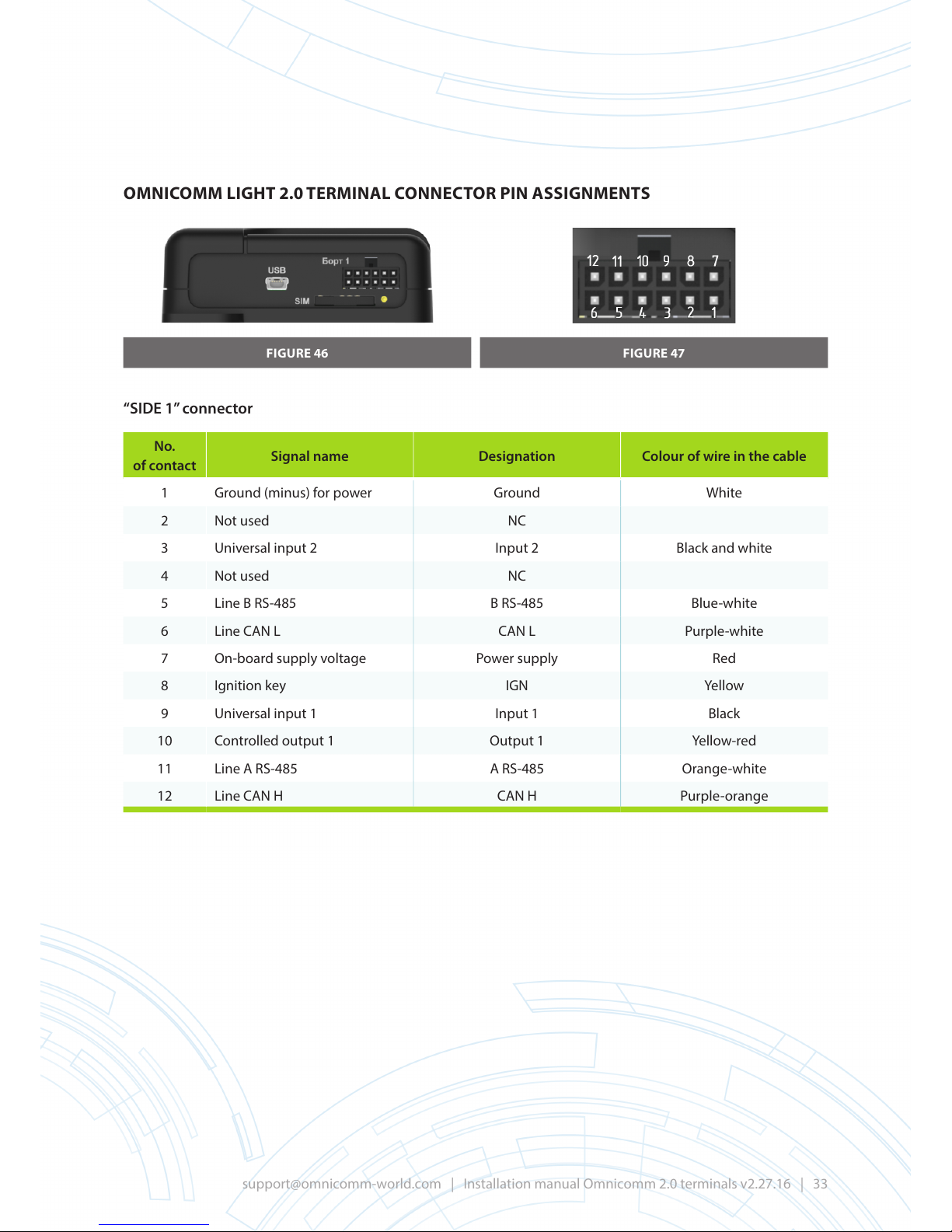
OMNICOMM LIGHT 2.0 TERMINAL CONNECTOR PIN ASSIGNMENTS
FIGURE 46 FIGURE 47
“SIDE 1” connector
No.
of contact
Signal name Designation Colour of wire in the cable
1 Ground (minus) for power Ground White
2 Not used NC
3 Universal input 2 Input 2 Black and white
4 Not used NC
5 Line B RS-485 B RS-485 Blue-white
6 Line CAN L CAN L Purple-white
7 On-board supply voltage Power supply Red
8 Ignition key IGN Yellow
9 Universal input 1 Input 1 Black
10 Controlled output 1 Output 1 Yellow-red
11 Line A RS-485 A RS-485 Orange-white
12 Line CAN H CAN H Purple-orange
Page 34
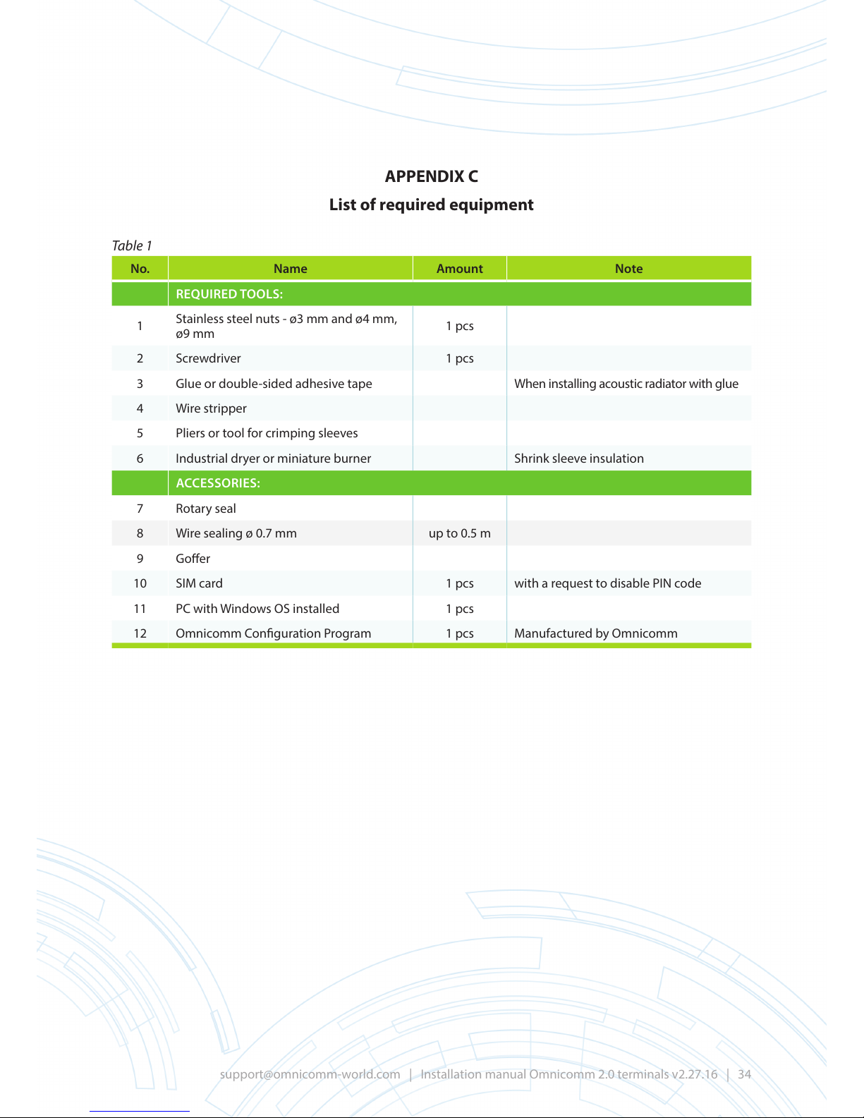
APPENDIX C
List of required equipment
Table 1
No. Name Amount Note
REQUIRED TOOLS:
1
Stainless steel nuts - ø3 mm and ø4 mm,
ø9 mm
1 pcs
2 Screwdriver 1 pcs
3 Glue or double-sided adhesive tape When installing acoustic radiator with glue
4 Wire stripper
5 Pliers or tool for crimping sleeves
6 Industrial dryer or miniature burner Shrink sleeve insulation
ACCESSORIES:
7 Rotary seal
8 Wire sealing ø 0.7 mm up to 0.5 m
9 Goer
10 SIM card 1 pcs with a request to disable PIN code
11 PC with Windows OS installed 1 pcs
12 Omnicomm Conguration Program 1 pcs Manufactured by Omnicomm
Page 35

APPENDIX D
Description of operating principles for universal inputs of Omnicomm2.0 Terminals
Universal inputs can be connected to one of three types of sensors:
• with analog output voltage signal;
• with impulse (frequency) output signal;
• with potential signal.
Analog voltage output signal is a signal in which the measurement sensor is proportional to the voltage
at its output. The higher the voltage, the greater the measured value (which is called directly proportional
to the signal) or the lower the voltage, the greater the measured value (the inversely proportional signal).
The Omnicomm Terminal can work with either directly proportional, or inversely proportional, to the signal.
The analog sensors can be classied as sensors that have no output signal voltage and current signal (the
most common signals being 4–20 mA and 0–20 mA). To connect the sensor to the Omnicomm Terminal,
you need to install a bypass resistor and measure the voltage drop on the Terminal (i.e. the signal current is
converted into a voltage signal perceived by the Omnicomm Terminal).
Analog voltage signal is measured by Omnicomm Terminal and is converted into a physical quantity
measured by sensor. Conversion is performed according to a linear law given by two points when
conguring the Omnicomm Terminal.
FIGURE 48. ASSIGNING THE LAW OF CONVERTING VOLTAGE INTO THE VALUE
OF THE MEASURED PHYSICAL QUANTITY
The average measured value obtained during the period of data collection and converted based on the
linear law is transmitted to Omnicomm Online.
Note: The Omnicomm Terminal collects data and transfers it to Omnicomm Online once during a given
period of time. Data collection period is specied during conguration of Omnicomm Congurator with
the parameter that carries the same title.
Impulse (or frequency) signal is a signal in which the result of measurement is modulated by frequency,
i.e. the greater the result of the measurement, the greater the number of impulses per unit time. For
impulse signal type, Omnicomm Terminal adds together the number of impulses (along the front, i.e. along
the front of the increasing signal) for the data collection period, multiplies the amount by the calibration
coecient of the impulse input and transmits the result to Omnicomm Online. Multiplication by calibration
coecient is needed to convert the number of impulses into the value of the physical quantity, measured
by sensors (for example, converting the number of impulses into engine rotation speed).
Page 36
The impulse signal is also used to count the number of events that occur more frequently than the specied
interval for collecting data. For example, if the task is to count the number of incoming public transport
passengers, the Terminal will sum up the number of times the door sensor was triggered and transmit
to Omnicomm Online the number of the passengers who entered (or exited) for each data collection
interval. In such a case, the calibration coecient must be preset as 1, because one triggering of the sensor
corresponds to one passenger.
Potential signal is a signal that indicates the occurrence of any event taking place less frequently than
the data collection period. It is necessary to capture the fact that the event occurred, but the exact time of
its occurrence is not important (the accuracy of time determination within the data collection period will
suce). These events can include switching certain equipment on, lowering of an operating part of the
vehicle, opening of a door, etc. A value from the sensor that has a potential signal is logical: on (logical unit)
or o (logical zero). This status can be recorded for a long time, i.e. longer than the data collection period.
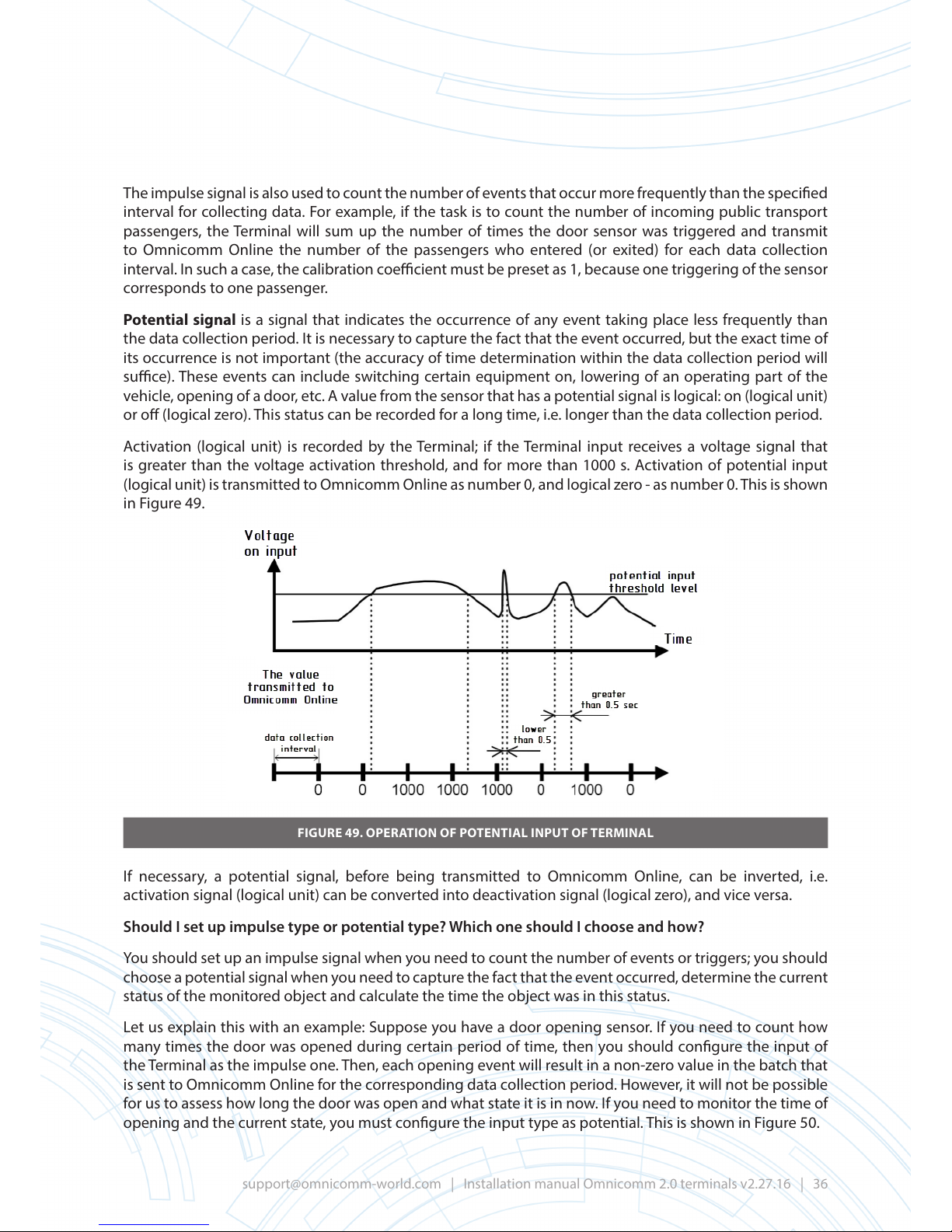
Activation (logical unit) is recorded by the Terminal; if the Terminal input receives a voltage signal that
is greater than the voltage activation threshold, and for more than 1000 s. Activation of potential input
(logical unit) is transmitted to Omnicomm Online as number 0, and logical zero - as number 0. This is shown
in Figure 49.
FIGURE 49. OPERATION OF POTENTIAL INPUT OF TERMINAL
If necessary, a potential signal, before being transmitted to Omnicomm Online, can be inverted, i.e.
activation signal (logical unit) can be converted into deactivation signal (logical zero), and vice versa.
Should I set up impulse type or potential type? Which one should I choose and how?
You should set up an impulse signal when you need to count the number of events or triggers; you should
choose a potential signal when you need to capture the fact that the event occurred, determine the current
status of the monitored object and calculate the time the object was in this status.
Let us explain this with an example: Suppose you have a door opening sensor. If you need to count how
many times the door was opened during certain period of time, then you should congure the input of
the Terminal as the impulse one. Then, each opening event will result in a non-zero value in the batch that
is sent to Omnicomm Online for the corresponding data collection period. However, it will not be possible
for us to assess how long the door was open and what state it is in now. If you need to monitor the time of
opening and the current state, you must congure the input type as potential. This is shown in Figure 50.
Page 37
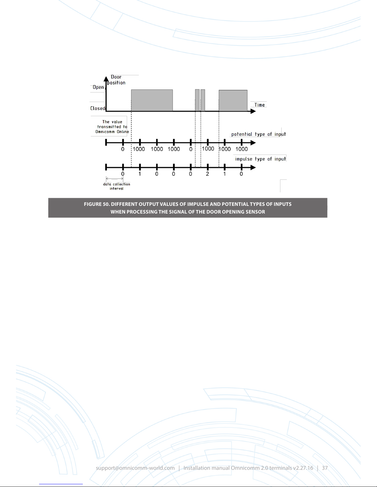
FIGURE 50. DIFFERENT OUTPUT VALUES OF IMPULSE AND POTENTIAL TYPES OF INPUTS
WHEN PROCESSING THE SIGNAL OF THE DOOR OPENING SENSOR
Page 38

APPENDIX E
Recommendations for the selection of sensors to connect to universal inputs
of Omnicomm 2.0 Terminals
Types of physical quantities, measured by sensors, types of sensors that are suitable for such measurement
and input types are listed in Table 2.
Table 2
Measured value Sensors/sensor types Input type
Consumption of fuel, reagents,
fertilisers, etc.
Instantaneous ow meters with impulse
transmitters
Impulse
(Frequency-modulated
signal, the frequency of
which is proportional
to the measured or
recorded value)
Monitoring of additional engine
frequency or any other additional
equipment working from power take-
o drive
Proximity sensor that determines the
frequency of rotation of the shaft (pinion,
drive gear etc.)
Fuel level in the additional fuel tank or
in the tank with hydraulic uid
Sensor of physical quantities, fuel level
sensor
LLS-AF in frequency output mode
Counting frequent (more frequent than
the collection period) events:
lifting/lowering of excavator bucket,
counting the number of passengers in
public transport, unloading/loading
goods from/to a conveyor, etc.
Contact Switches, Proximity Sensors that
are triggered by each event
Fuel level in the additional fuel tank or
in the tank with hydraulic uid
Sensor of physical quantities, LLS-AF fuel
level sensor in the analog or frequency
output mode (connection method
recommended for LLS-AF)
Analog
(Voltage or current
signal, value of which
is proportional or
inversely proportional
to the measured value)
Temperature, pressure, humidity, etc.
Sensors of temperature, pressure,
humidity, etc. or analog converters with
output voltage or current signal
Turning on or o of additional
equipment (engine, burner,
attachments)
Proximity sensors, physical value sensor
(for example, pressure) or other signal
sources
Potential (Signal for
turning something on,
accompanied by the
emergence of certain
voltage (potential)
on a wire)
Counting of rare events (less frequent
than period of data collection):
passenger getting in a taxi, truck body
lifting, lowering of a plough, etc.
Contact Switches, Proximity Sensors
Please remember that before installing a new sensor, we recommend that you examine the vehicle and
check if any other sensor or signal that can provide you with information on the correct physical quantities
that were already installed there.
Analog temperature and pressure sensors are selected primarily based on their installation capabilities.
The design of the sensor should allow for its installation, and the measured value must be in the range of
the sensor. The sensor also must have a current or voltage output signal. If the sensor has resistance output
signal or output signal of another type, it must be used together with suitable normalising transducer.
Note: “normalising transducer” is an umbrella term for a group of devices that converts one output signal
into another, usually into a uniform current or voltage signal. They may have such additional functions as
Page 39

signal linearisation, compensation for additional factors, protection, galvanic isolation, etc., and therefore
may have dierent names.
Proximity impulse sensors with N-P-N output transistor and “open collector” output are typically used.
Sensors can have various operational principles, but the most common sensors are based on four principles:
• Capacitive: are triggered when brought into the zone of sensor sensitivity of the certain matter
(metal, plastic, glass, liquid, etc.). Their working range reaches up to 30 mm. Can be falsely
triggered by dust, dirt, rain, etc., and therefore are usually used in clean conditions and indoors.
• Induction: are triggered when brought into the metal zone. Available with up to 30 mm working
range. More protected from false positives, but do not work with non-metallic objects.
• With hall eect or reed relay: are triggered when brought into magnet working range.
• Optical: are triggered by interruption of optical path. Some also work from reected ux (in this
case, emitter and receiver are in the same casing) or from ux radiator (emitter and receiver are
made separately and may be positioned at a signicant distance from each other).
Contact sensors (e.g. buttons, end switches, relays, max level sensors, maximum pressure sensors, bimetallic
temperature switches, etc.) or proximity sensors with N-P-N transistor may act as potential sensors. These
contact and proximity sensors commute power voltage or ground, and thus lead to changes in voltage at
the potential input of the Terminal. Analog sensors, described above, can also act as potential sensors.
Page 40
APPENDIX F
Examples of settings when using dierent methods
to connect to universal inputs of Omnicomm2.0 Terminals
Example 1. Omnicomm analog temperature sensor
Purpose: to measure the temperature
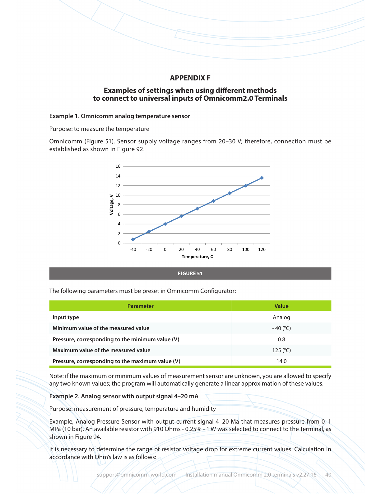
Omnicomm (Figure 51). Sensor supply voltage ranges from 20–30 V; therefore, connection must be
established as shown in Figure 92.
FIGURE 51
The following parameters must be preset in Omnicomm Congurator:
Parameter Value
Input type Analog
Minimum value of the measured value - 40 (°С)
Pressure, corresponding to the minimum value (V) 0.8
Maximum value of the measured value 125 (°С)
Pressure, corresponding to the maximum value (V) 14.0
Note: if the maximum or minimum values of measurement sensor are unknown, you are allowed to specify
any two known values; the program will automatically generate a linear approximation of these values.
Example 2. Analog sensor with output signal 4–20 mA
Purpose: measurement of pressure, temperature and humidity
Example, Analog Pressure Sensor with output current signal 4–20 Ma that measures pressure from 0–1
MPa (10 bar). An available resistor with 910 Ohms - 0.25% - 1 W was selected to connect to the Terminal, as
shown in Figure 94.
It is necessary to determine the range of resistor voltage drop for extreme current values. Calculation in
accordance with Ohm’s law is as follows:
Page 41
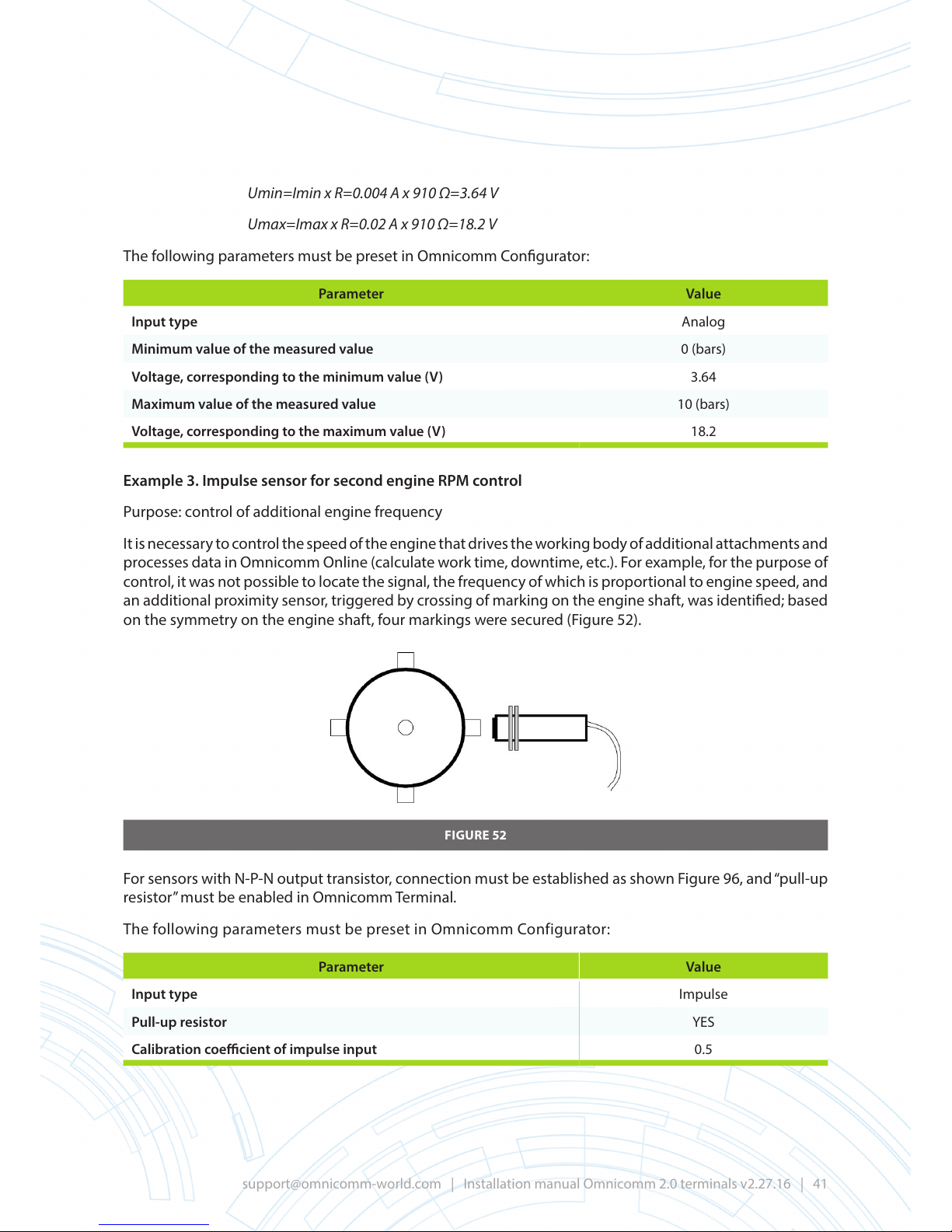
Umin=Imin x R=0.004А x 910Ω=3.64V
Umax=Imax x R=0.02А x 910Ω=18.2V
The following parameters must be preset in Omnicomm Congurator:
Parameter Value
Input type Analog
Minimum value of the measured value 0 (bars)
Voltage, corresponding to the minimum value (V) 3.64
Maximum value of the measured value 10 (bars)
Voltage, corresponding to the maximum value (V) 18.2
Example 3. Impulse sensor for second engine RPM control
Purpose: control of additional engine frequency
It is necessary to control the speed of the engine that drives the working body of additional attachments and
processes data in Omnicomm Online (calculate work time, downtime, etc.). For example, for the purpose of
control, it was not possible to locate the signal, the frequency of which is proportional to engine speed, and
an additional proximity sensor, triggered by crossing of marking on the engine shaft, was identied; based
on the symmetry on the engine shaft, four markings were secured (Figure 52).
FIGURE 52
For sensors with N-P-N output transistor, connection must be established as shown Figure 96, and “pull-up
resistor” must be enabled in Omnicomm Terminal.
The following parameters must be preset in Omnicomm Configurator:
Parameter Value
Input type Impulse
Pull-up resistor YES
Calibration coecient of impulse input 0.5
Page 42

Method of calculation of calibration coecient. It is necessary to convert the number of impulses into shaft
speed (in revolutions/min). Data collection timer is 30 s.
• four impulses come per shaft rotation, i.e., to determine the number of turns, it is necessary to
multiply the number of impulses by 0.25.
• The Terminal sums the number of impulses for the period of «data collection timer» - in our case,
for ½ minute (30 s) - and in order to obtain the number of revolutions per minute, it is necessary
to multiply the number of revolutions for data collection timer by two.
• the resulting input calibration coecient: 0.25 x 2 = 0.5
Example 4. Potential sensor for lifting control of dump truck body (option 1)
Purpose: control of lifting the body of a dump truck.
Let us consider the option of using a contact sensor (similarly, a proximity sensor of any operational type
may be connected), bearing in mind that the sensor contacts disconnect, when the dump truck body is
lifted.
The sensor is connected according to Figure 95.
The following parameters must be preset in Omnicomm Congurator:
Parameter Value
Input type Potential
Voltage threshold for actuation (V) 4.5
Pull-up resistor YES
Inversion of potential signal NO
Explanation:
• With closed contact of the sensor, voltage, close to 0 V (“ground” voltage), occurs at the input
of the Omnicomm Terminal. When contact is broken, voltage with a value, close to the supply
voltage value, is delivered via actuated pull-up resistance. Therefore, you must set the threshold
for switching between zero and the value of the supplied voltage, for example, leave the default
value at 4.5 V.
• The sensor contacts are opened when lifting the body.
With closed contacts, at Omnicomm Terminal input, voltage of approximately 0 V (Terminal input
is grounded) is less than the value of “Voltage threshold for actuation” and is recognised as the
deactivation signal (logical “0”).
When sensor contacts are broken, voltage is supplied to Terminal input via a pull-up resistor;
the value of the voltage is greater than the value of “Voltage threshold for actuation” and is
recognised as the activation signal (logical “1”). Consequently, it is not required to invert the
signal. If sensor contacts are closed when lifting the body, it would be necessary to actuate the
inversion of the signal.
Example 5. Potential body dump truck lifting control sensor (option 2)
Purpose: control of lifting the body of a dump truck.
For control measure, pressure sensor with analog output signal, embedded in a hydraulic main line of body
lifting mechanism, is used. However, the sensor is not congured as an analog sensor, but as a potential
sensor.
Page 43

Based on conducted experiments or calculations, similar to examples 1 and 2 specied in Appendix D, we
can determine:
• with normal pressure in the main line, voltage at the output of the sensor equals 2–2.5V,
• with increasing pressure, which is necessary in order to lift the body, the voltage at the output
exceeds 3.5 V (and can reach 15 V and higher).
The following parameters must be preset in Omnicomm Congurator:
Parameter Value
Input type Potential
Voltage threshold for actuation (V) 3.3
Pull-up resistor NO
Inversion of potential signal NO
Explanation:
• The threshold voltage is selected from a range of 2.5–3.5 V, closer to 3.5 V, but not close to the
extreme value to eliminate false positives.
• Pull-up resistor is disabled: as sensor sends the voltage signal, additional pull-up resistor will
increase the current via the sensor and will adversely aect the measurement results.
Inversion of the signal is not required: the input voltage that is above the threshold corresponds to the
state of activation (logical “1”).
Page 44
APPENDIX G:
Connection diagrams for Omnicomm Pro 2.0, Pro 2.0 WiFi,
Optim 2.0 and Light 2.0
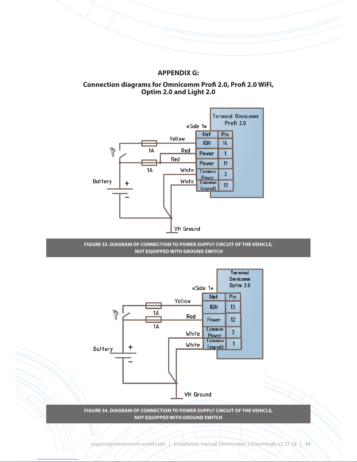
FIGURE 53. DIAGRAM OF CONNECTION TO POWER SUPPLY CIRCUIT OF THE VEHICLE,
NOT EQUIPPED WITH GROUND SWITCH
FIGURE 54. DIAGRAM OF CONNECTION TO POWER SUPPLY CIRCUIT OF THE VEHICLE,
NOT EQUIPPED WITH GROUND SWITCH
Page 45
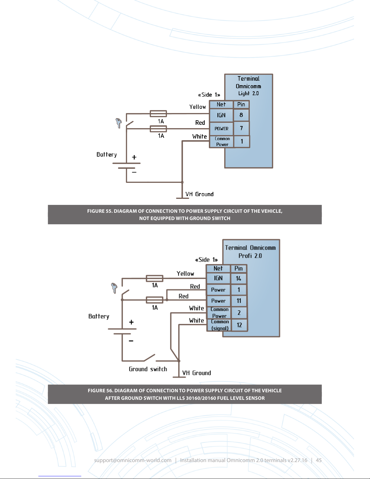
FIGURE 55. DIAGRAM OF CONNECTION TO POWER SUPPLY CIRCUIT OF THE VEHICLE,
NOT EQUIPPED WITH GROUND SWITCH
FIGURE 56. DIAGRAM OF CONNECTION TO POWER SUPPLY CIRCUIT OF THE VEHICLE
AFTER GROUND SWITCH WITH LLS 30160/20160 FUEL LEVEL SENSOR
Page 46
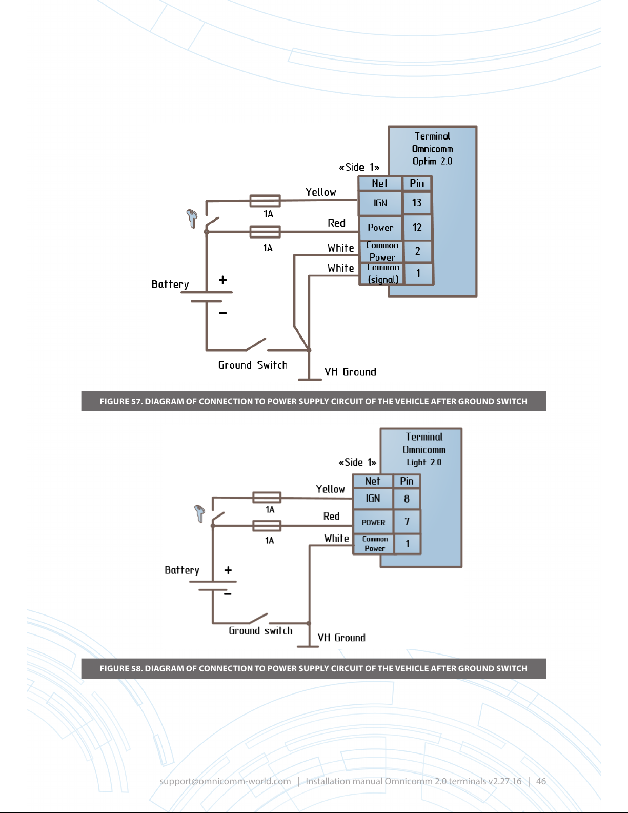
FIGURE 57. DIAGRAM OF CONNECTION TO POWER SUPPLY CIRCUIT OF THE VEHICLE AFTER GROUND SWITCH
FIGURE 58. DIAGRAM OF CONNECTION TO POWER SUPPLY CIRCUIT OF THE VEHICLE AFTER GROUND SWITCH
Page 47
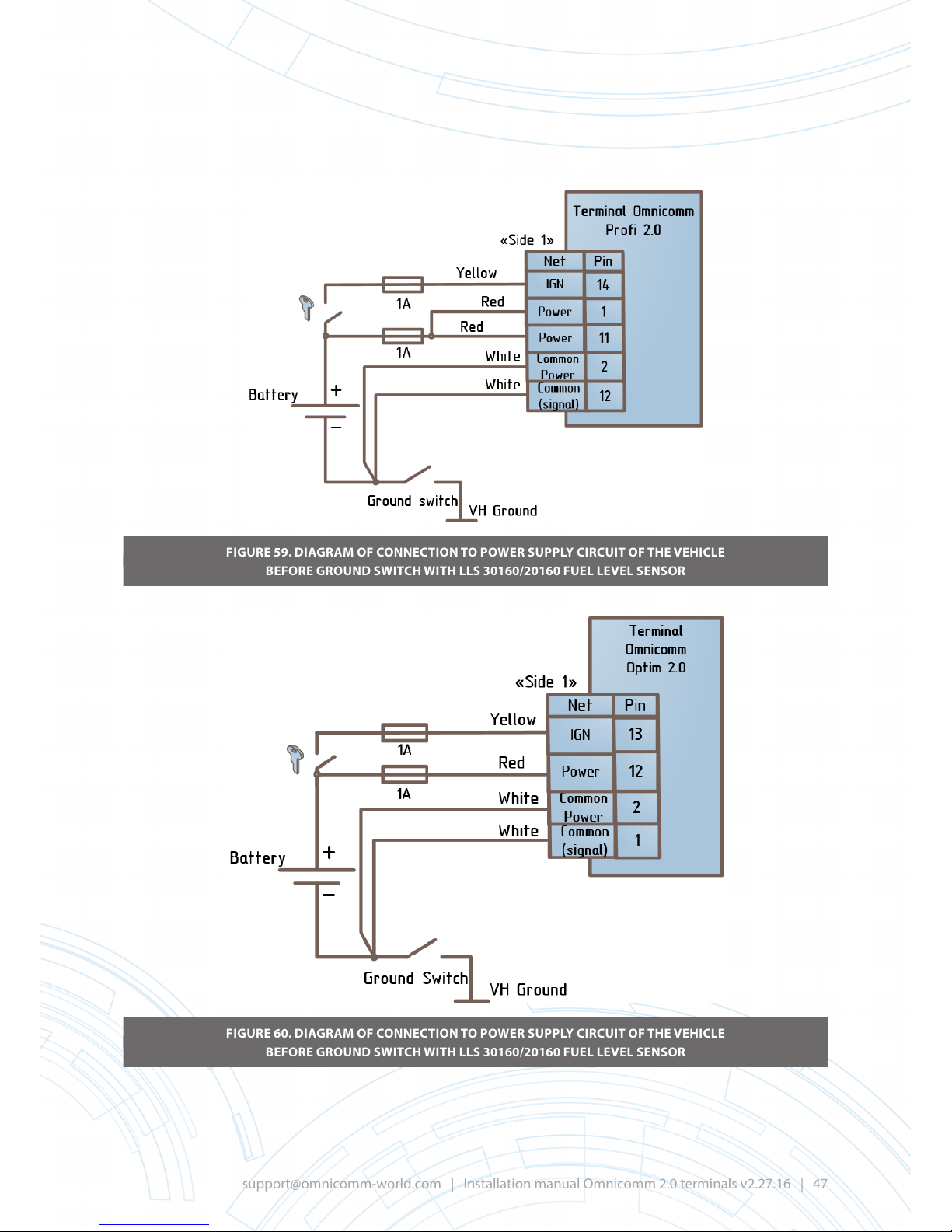
FIGURE 59. DIAGRAM OF CONNECTION TO POWER SUPPLY CIRCUIT OF THE VEHICLE
BEFORE GROUND SWITCH WITH LLS 30160/20160 FUEL LEVEL SENSOR
FIGURE 60. DIAGRAM OF CONNECTION TO POWER SUPPLY CIRCUIT OF THE VEHICLE
BEFORE GROUND SWITCH WITH LLS 30160/20160 FUEL LEVEL SENSOR
Page 48
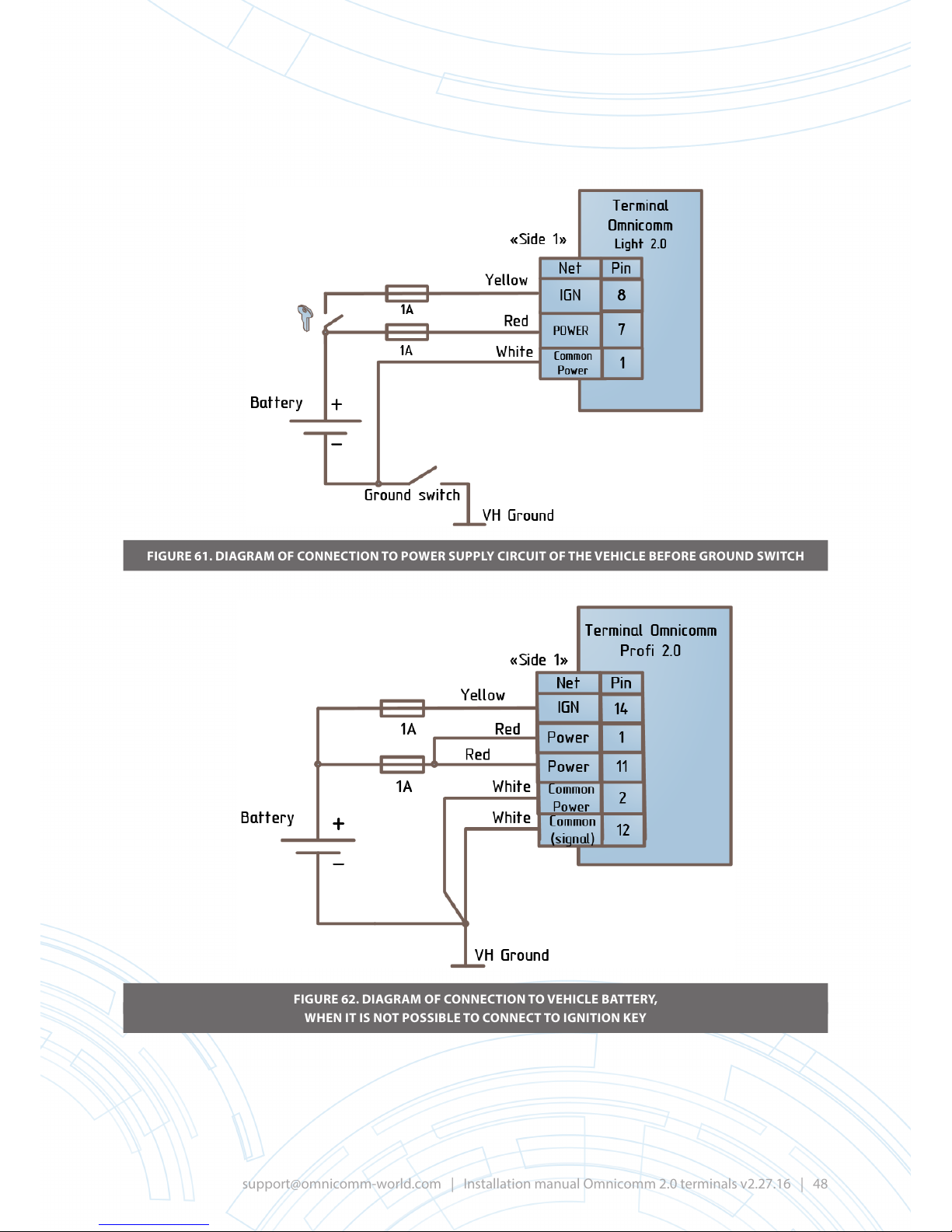
FIGURE 61. DIAGRAM OF CONNECTION TO POWER SUPPLY CIRCUIT OF THE VEHICLE BEFORE GROUND SWITCH
FIGURE 62. DIAGRAM OF CONNECTION TO VEHICLE BATTERY,
WHEN IT IS NOT POSSIBLE TO CONNECT TO IGNITION KEY
Page 49
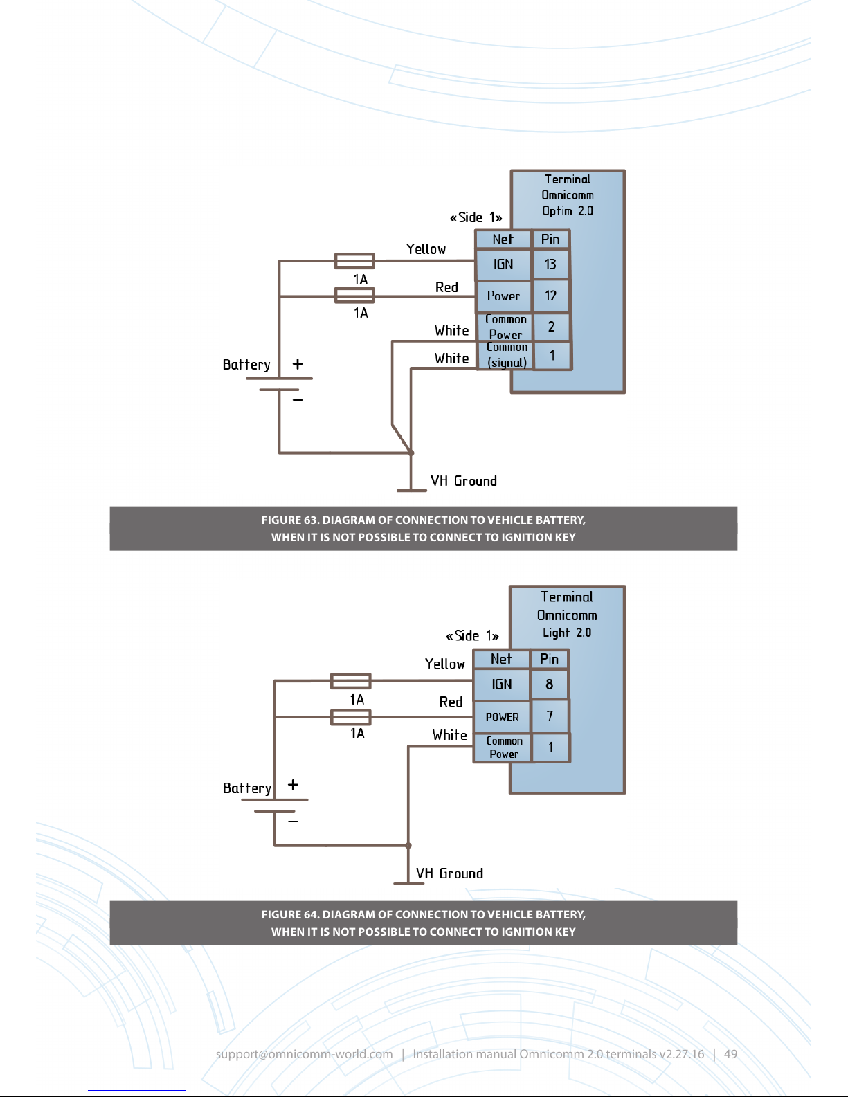
FIGURE 63. DIAGRAM OF CONNECTION TO VEHICLE BATTERY,
WHEN IT IS NOT POSSIBLE TO CONNECT TO IGNITION KEY
FIGURE 64. DIAGRAM OF CONNECTION TO VEHICLE BATTERY,
WHEN IT IS NOT POSSIBLE TO CONNECT TO IGNITION KEY
Page 50
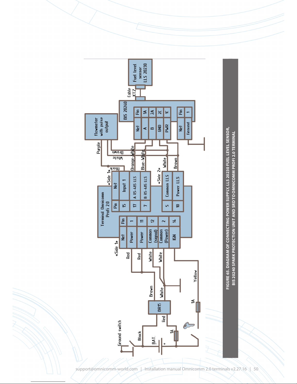
FIGURE 65. DIAGRAM OF CONNECTING POWER SUPPLY, LLS 20230 FUEL LEVEL SENSOR,
BIS 20240 SPARK PROTECTION UNIT AND SRD TO OMNICOMM PROFI 2.0 TERMINAL
Page 51
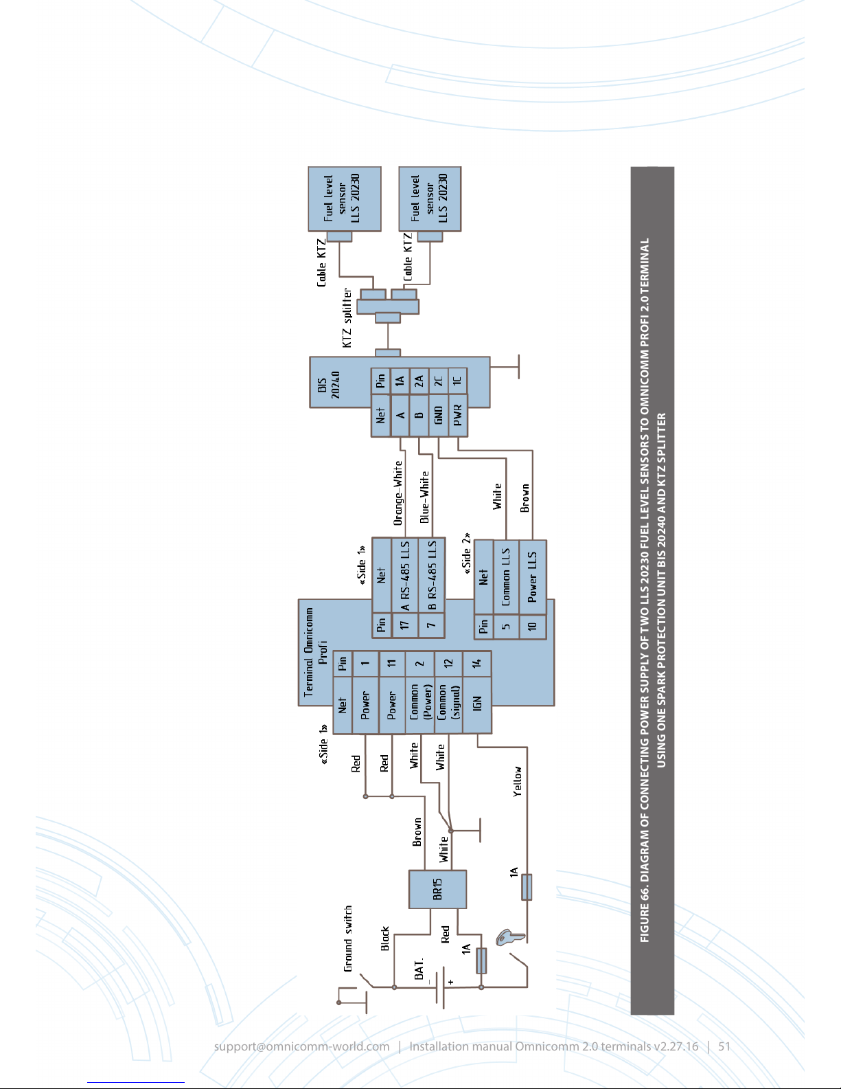
FIGURE 66. DIAGRAM OF CONNECTING POWER SUPPLY OF TWO LLS 20230 FUEL LEVEL SENSORS TO OMNICOMM PROFI 2.0 TERMINAL
USING ONE SPARK PROTECTION UNIT BIS 20240 AND KTZ SPLITTER
Page 52
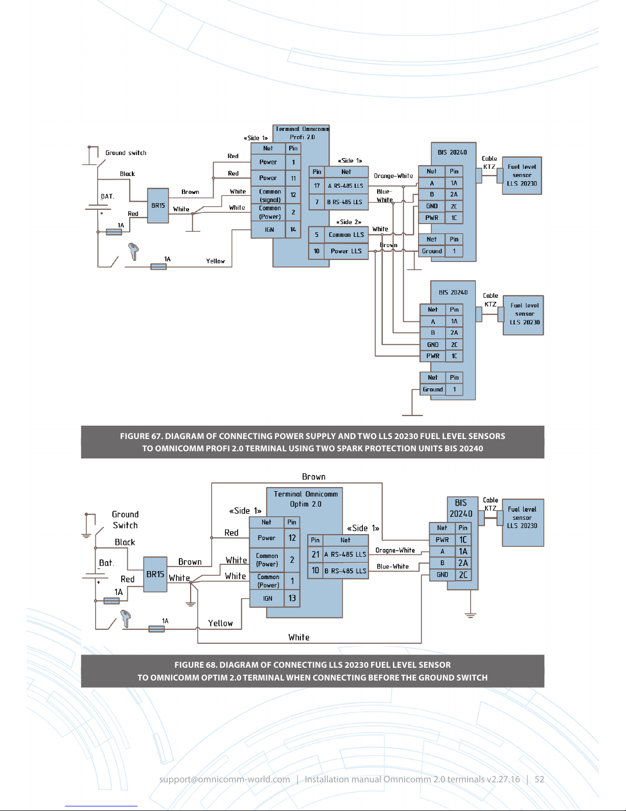
FIGURE 67. DIAGRAM OF CONNECTING POWER SUPPLY AND TWO LLS 20230 FUEL LEVEL SENSORS
TO OMNICOMM PROFI 2.0 TERMINAL USING TWO SPARK PROTECTION UNITS BIS 20240
FIGURE 68. DIAGRAM OF CONNECTING LLS 20230 FUEL LEVEL SENSOR
TO OMNICOMM OPTIM 2.0 TERMINAL WHEN CONNECTING BEFORE THE GROUND SWITCH
Page 53
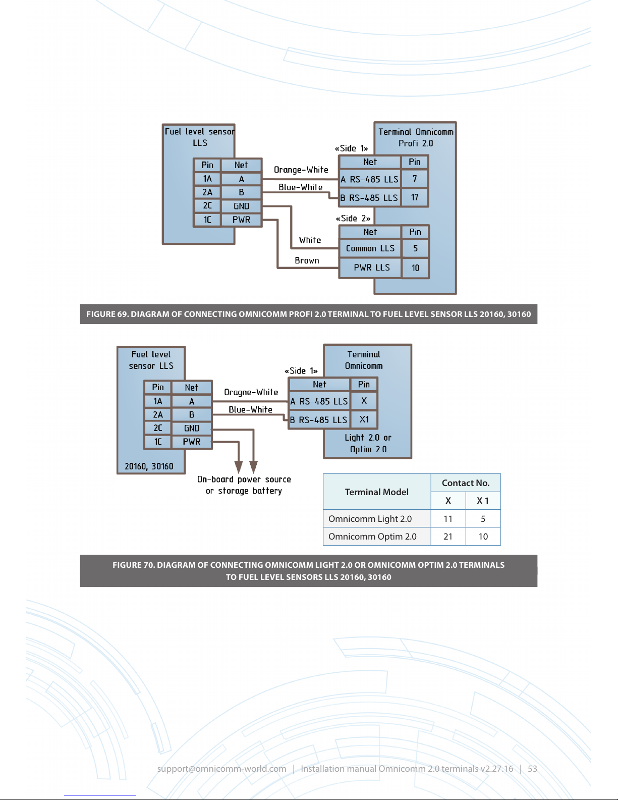
FIGURE 69. DIAGRAM OF CONNECTING OMNICOMM PROFI 2.0 TERMINAL TO FUEL LEVEL SENSOR LLS 20160, 30160
FIGURE 70. DIAGRAM OF CONNECTING OMNICOMM LIGHT 2.0 OR OMNICOMM OPTIM 2.0 TERMINALS
TO FUEL LEVEL SENSORS LLS 20160, 30160
Terminal Model
Contact No.
X X 1
Omnicomm Light 2.0 11 5
Omnicomm Optim 2.0 21 10
Page 54
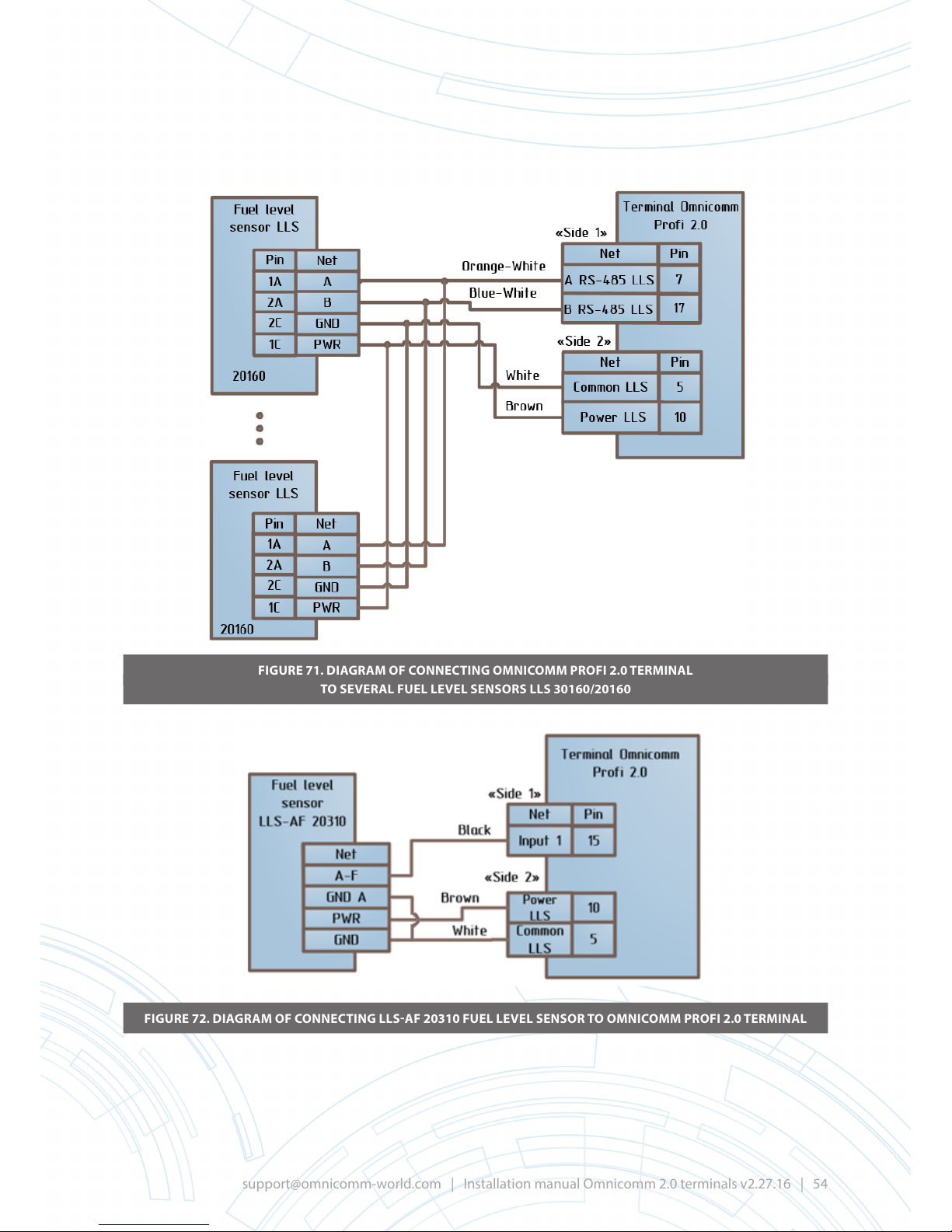
FIGURE 71. DIAGRAM OF CONNECTING OMNICOMM PROFI 2.0 TERMINAL
TO SEVERAL FUEL LEVEL SENSORS LLS 30160/20160
FIGURE 72. DIAGRAM OF CONNECTING LLS-AF 20310 FUEL LEVEL SENSOR TO OMNICOMM PROFI 2.0 TERMINAL
Page 55
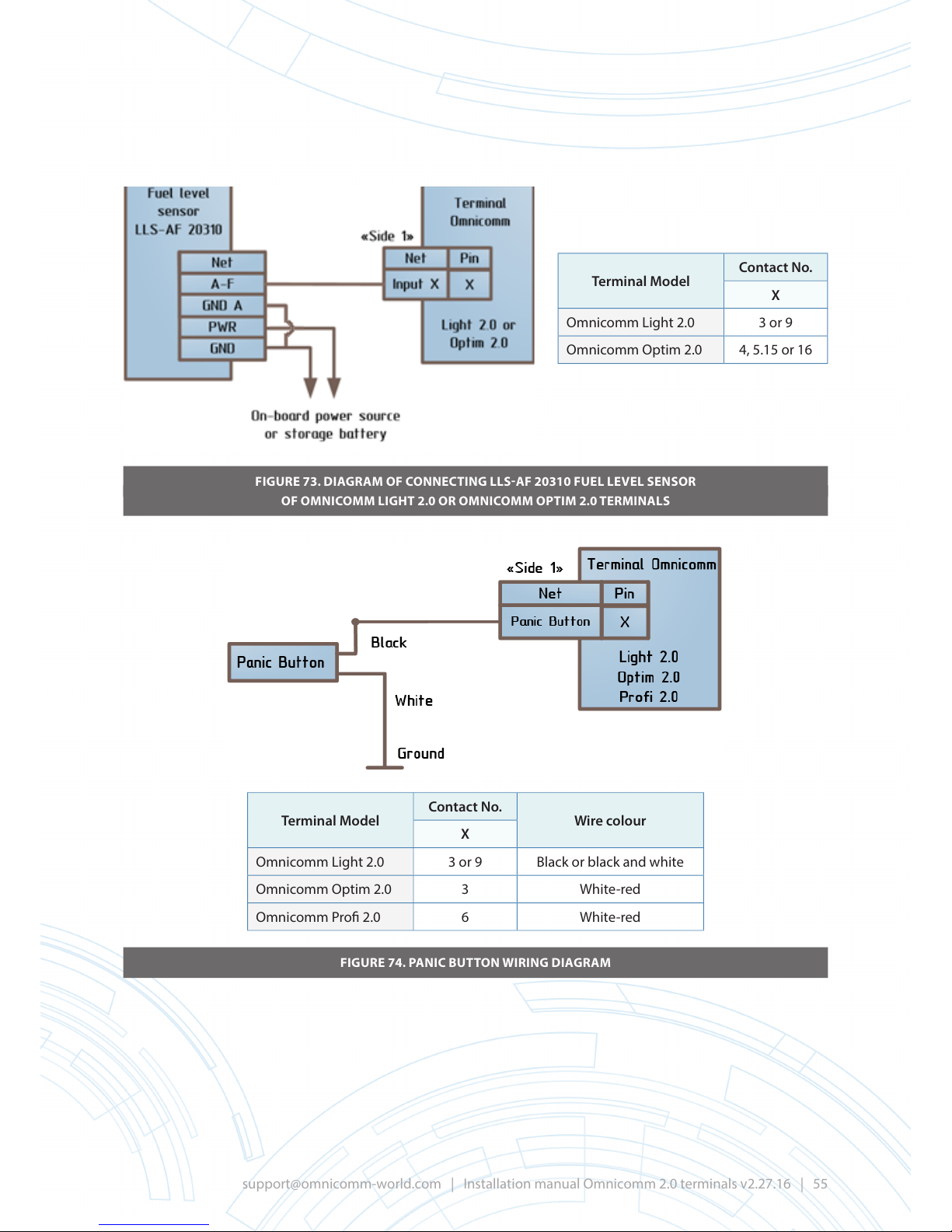
FIGURE 73. DIAGRAM OF CONNECTING LLS-AF 20310 FUEL LEVEL SENSOR
OF OMNICOMM LIGHT2.0 OR OMNICOMM OPTIM 2.0 TERMINALS
FIGURE 74. PANIC BUTTON WIRING DIAGRAM
Terminal Model
Contact No.
X
Omnicomm Light 2.0 3 or 9
Omnicomm Optim 2.0 4, 5.15 or 16
Terminal Model
Contact No.
Wire colour
X
Omnicomm Light 2.0 3 or 9 Black or black and white
Omnicomm Optim 2.0 3 White-red
Omnicomm Pro 2.0 6 White-red
Page 56
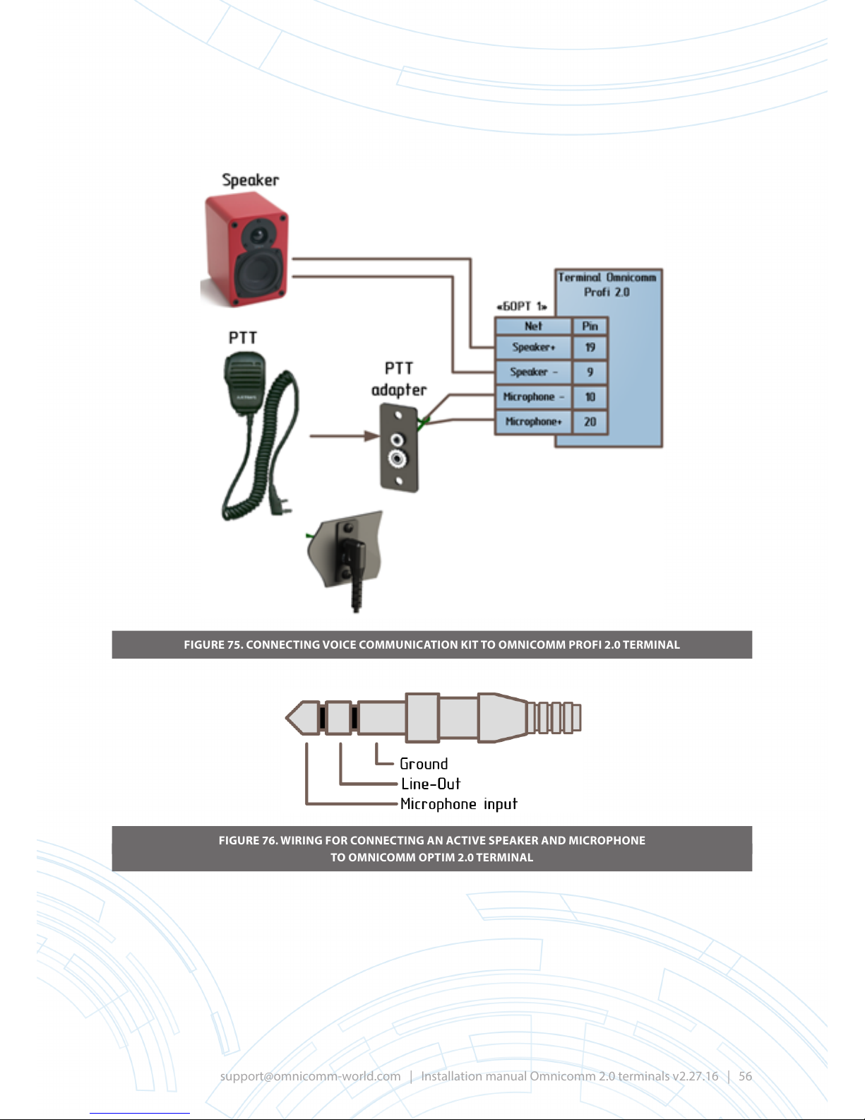
FIGURE 75. CONNECTING VOICE COMMUNICATION KIT TO OMNICOMM PROFI 2.0 TERMINAL
FIGURE 76. WIRING FOR CONNECTING AN ACTIVE SPEAKER AND MICROPHONE
TO OMNICOMM OPTIM 2.0 TERMINAL
Page 57
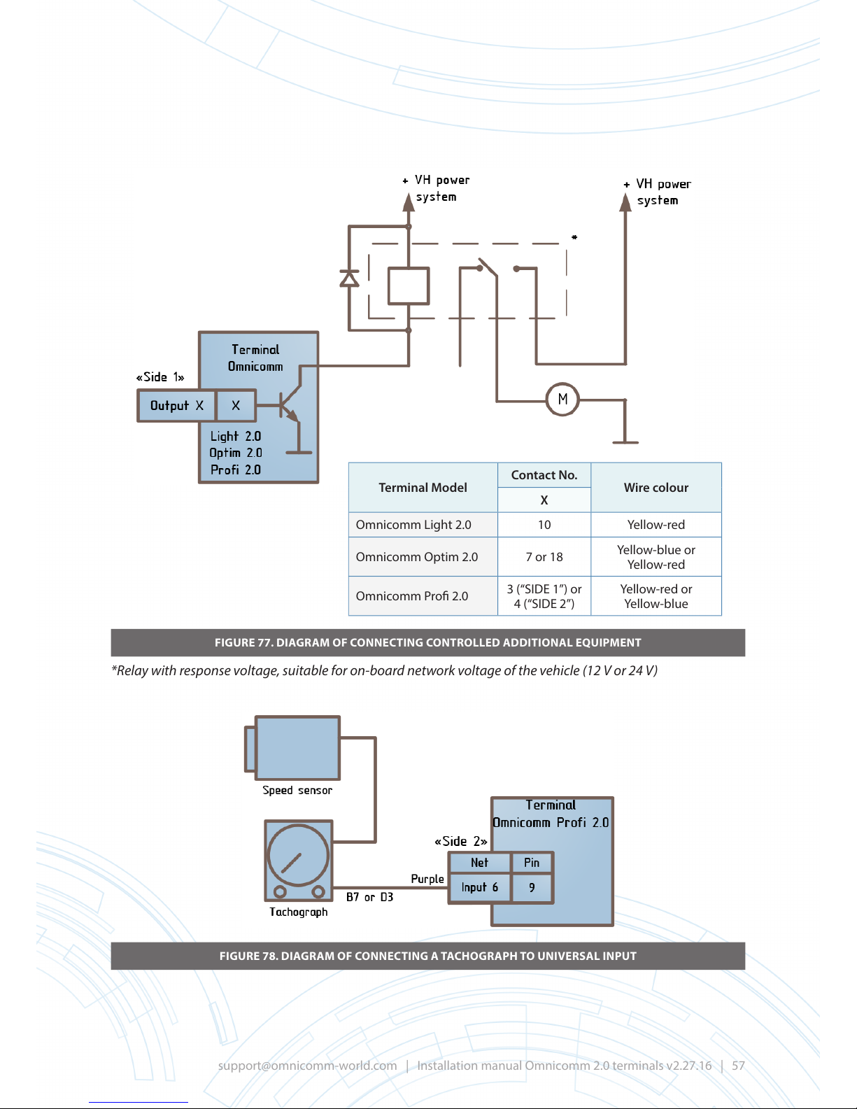
FIGURE 77. DIAGRAM OF CONNECTING CONTROLLED ADDITIONAL EQUIPMENT
*Relay with response voltage, suitable for on-board network voltage of the vehicle (12 V or 24 V)
FIGURE 78. DIAGRAM OF CONNECTING A TACHOGRAPH TO UNIVERSAL INPUT
Terminal Model
Contact No.
Wire colour
X
Omnicomm Light 2.0 10 Yellow-red
Omnicomm Optim 2.0 7 or 18
Yellow-blue or
Yellow-red
Omnicomm Pro 2.0
3 (“SIDE 1”) or
4 (“SIDE 2”)
Yellow-red or
Yellow-blue
Page 58
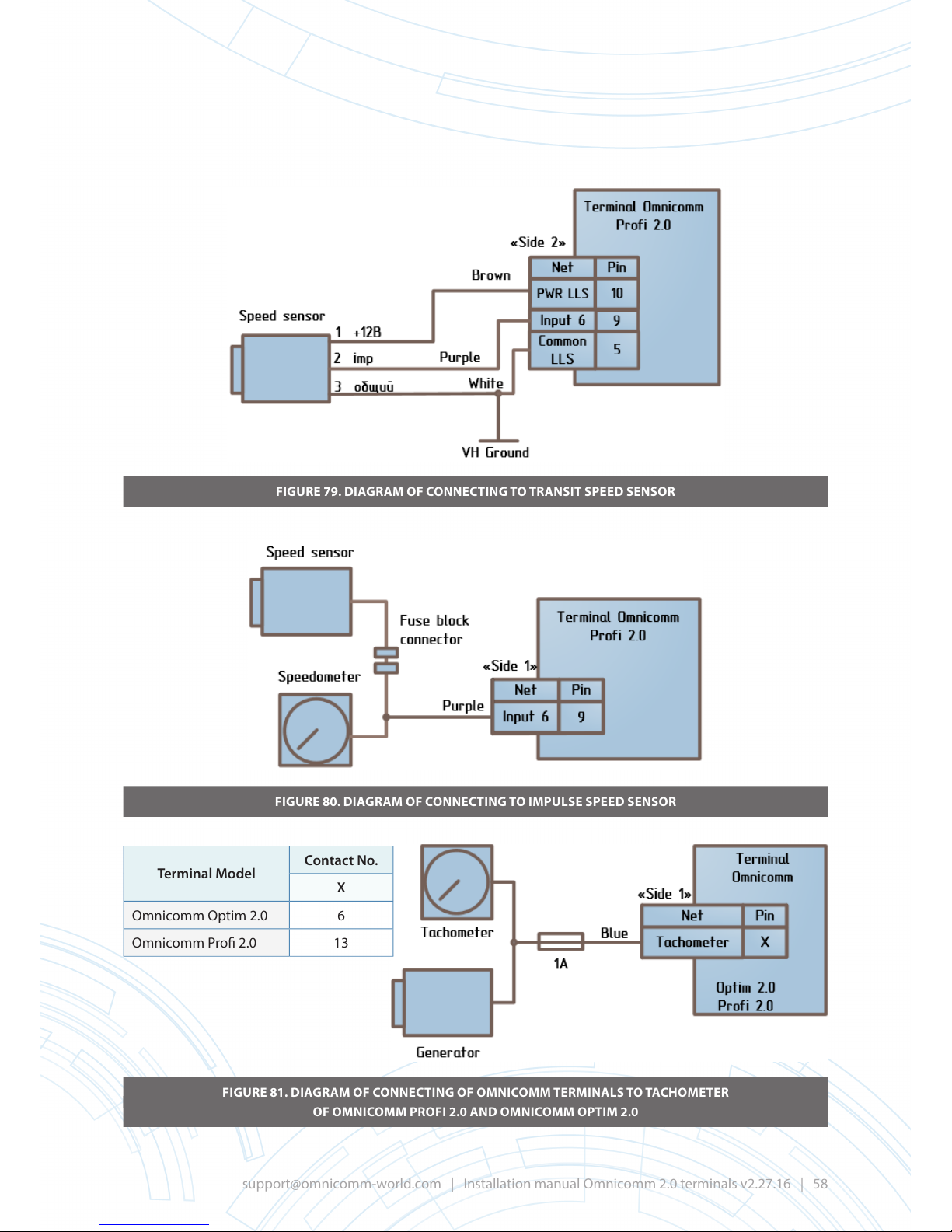
FIGURE 79. DIAGRAM OF CONNECTING TO TRANSIT SPEED SENSOR
FIGURE 80. DIAGRAM OF CONNECTING TO IMPULSE SPEED SENSOR
FIGURE 81. DIAGRAM OF CONNECTING OF OMNICOMM TERMINALS TO TACHOMETER
OF OMNICOMM PROFI 2.0 AND OMNICOMM OPTIM 2.0
Terminal Model
Contact No.
X
Omnicomm Optim 2.0 6
Omnicomm Pro 2.0 13
Page 59
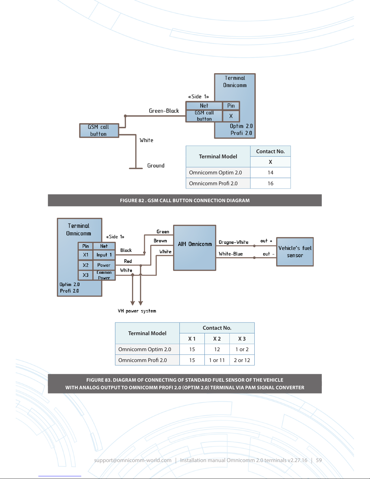
FIGURE 82 . GSM CALL BUTTON CONNECTION DIAGRAM
FIGURE 83. DIAGRAM OF CONNECTING OF STANDARD FUEL SENSOR OF THE VEHICLE
WITH ANALOG OUTPUT TO OMNICOMM PROFI 2.0 (OPTIM 2.0) TERMINAL VIA PAM SIGNAL CONVERTER
Terminal Model
Contact No.
X
Omnicomm Optim 2.0 14
Omnicomm Pro 2.0 16
Terminal Model
Contact No.
X 1 X 2 X 3
Omnicomm Optim 2.0 15 12 1 or 2
Omnicomm Pro 2.0 15 1 or 11 2 or 12
Page 60
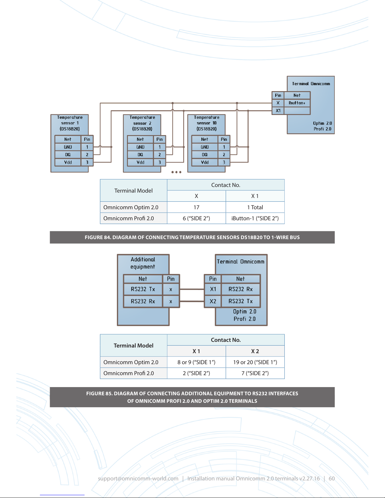
Terminal Model
Contact No.
X X 1
Omnicomm Optim 2.0 17 1 Total
Omnicomm Pro 2.0 6 (“SIDE 2”) iButton-1 (“SIDE 2”)
FIGURE 84. DIAGRAM OF CONNECTING TEMPERATURE SENSORS DS18B20 TO 1-WIRE BUS
FIGURE 85. DIAGRAM OF CONNECTING ADDITIONAL EQUIPMENT TO RS232 INTERFACES
OF OMNICOMM PROFI 2.0 AND OPTIM 2.0 TERMINALS
Terminal Model
Contact No.
X 1 X 2
Omnicomm Optim 2.0 8 or 9 (“SIDE 1”) 19 or 20 (“SIDE 1”)
Omnicomm Pro 2.0 2 (“SIDE 2”) 7 (“SIDE 2”)
Page 61
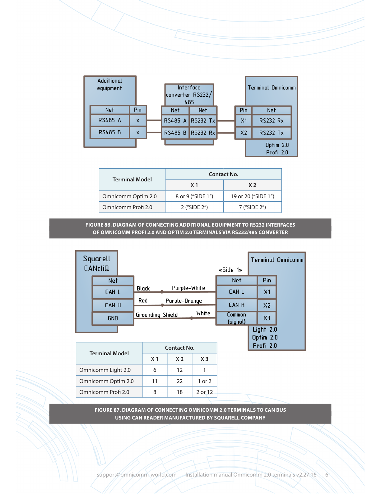
FIGURE 86. DIAGRAM OF CONNECTING ADDITIONAL EQUIPMENT TO RS232 INTERFACES
OF OMNICOMM PROFI 2.0 AND OPTIM 2.0 TERMINALS VIA RS232/485 CONVERTER
FIGURE 87. DIAGRAM OF CONNECTING OMNICOMM 2.0 TERMINALS TO CAN BUS
USING CAN READER MANUFACTURED BY SQUARELL COMPANY
Terminal Model
Contact No.
X 1 X 2
Omnicomm Optim 2.0 8 or 9 (“SIDE 1”) 19 or 20 (“SIDE 1”)
Omnicomm Pro 2.0 2 (“SIDE 2”) 7 (“SIDE 2”)
Terminal Model
Contact No.
X 1 X 2 X 3
Omnicomm Light 2.0 6 12 1
Omnicomm Optim 2.0 11 22 1 or 2
Omnicomm Pro 2.0 8 18 2 or 12
Page 62
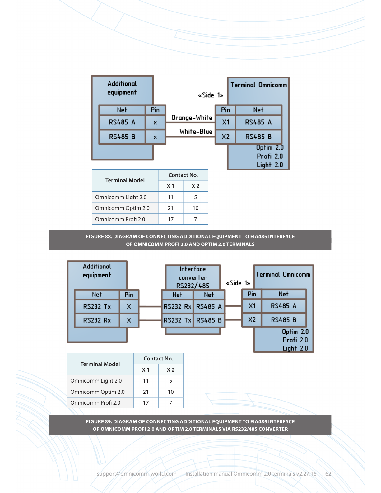
FIGURE 88. DIAGRAM OF CONNECTING ADDITIONAL EQUIPMENT TO EIA485 INTERFACE
OF OMNICOMM PROFI 2.0 AND OPTIM 2.0 TERMINALS
FIGURE 89. DIAGRAM OF CONNECTING ADDITIONAL EQUIPMENT TO EIA485 INTERFACE
OF OMNICOMM PROFI 2.0 AND OPTIM 2.0 TERMINALS VIA RS232/485 CONVERTER
Terminal Model
Contact No.
X 1 X 2
Omnicomm Light 2.0 11 5
Omnicomm Optim 2.0 21 10
Omnicomm Pro 2.0 17 7
Terminal Model
Contact No.
X 1 X 2
Omnicomm Light 2.0 11 5
Omnicomm Optim 2.0 21 10
Omnicomm Pro 2.0 17 7
Page 63
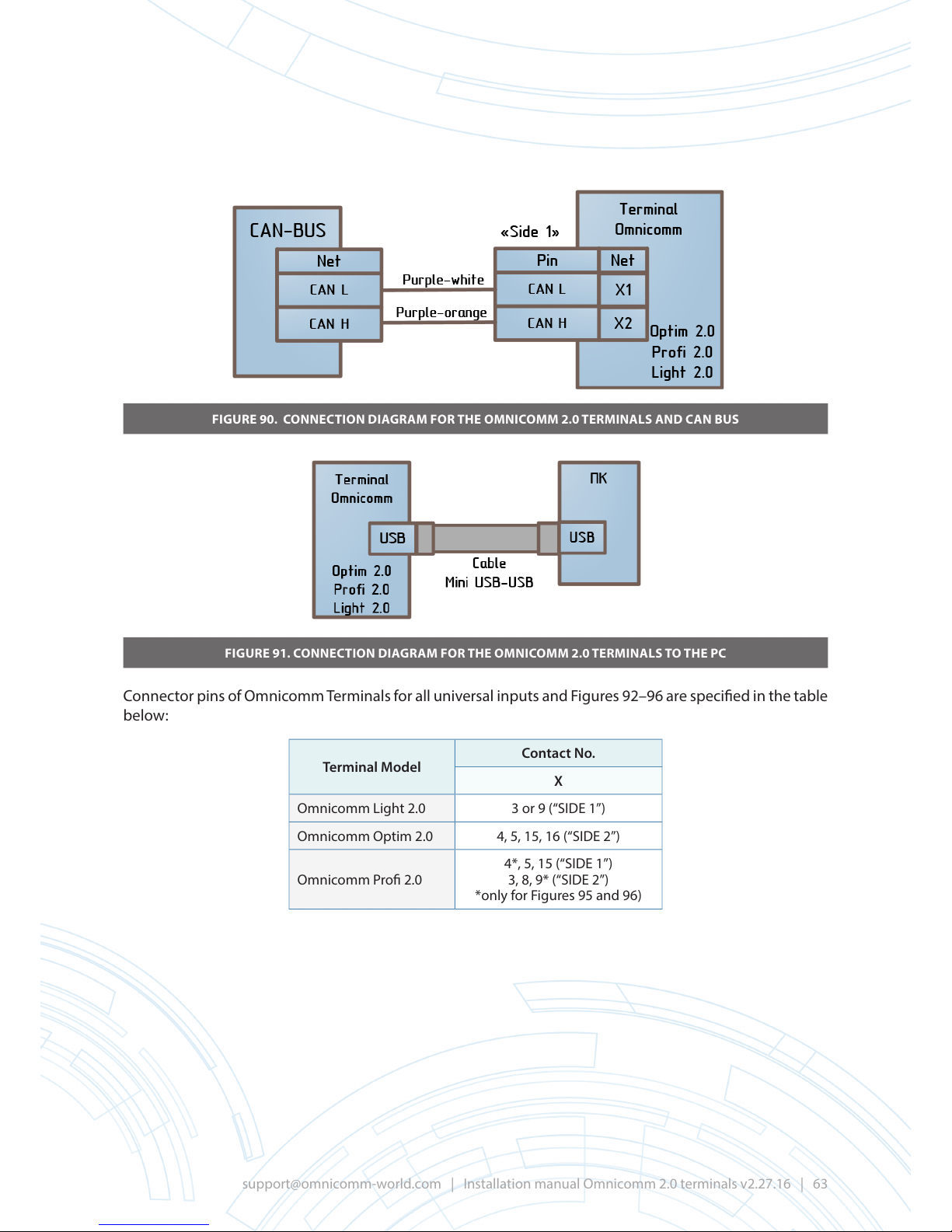
FIGURE 90. CONNECTION DIAGRAM FOR THE OMNICOMM 2.0 TERMINALS AND CAN BUS
FIGURE 91. CONNECTION DIAGRAM FOR THE OMNICOMM 2.0 TERMINALS TO THE PC
Connector pins of Omnicomm Terminals for all universal inputs and Figures 92–96 are specied in the table
below:
Terminal Model
Contact No.
X
Omnicomm Light 2.0 3 or 9 (“SIDE 1”)
Omnicomm Optim 2.0 4, 5, 15, 16 (“SIDE 2”)
Omnicomm Pro 2.0
4*, 5, 15 (“SIDE 1”)
3, 8, 9* (“SIDE 2”)
*only for Figures 95 and 96)
Page 64
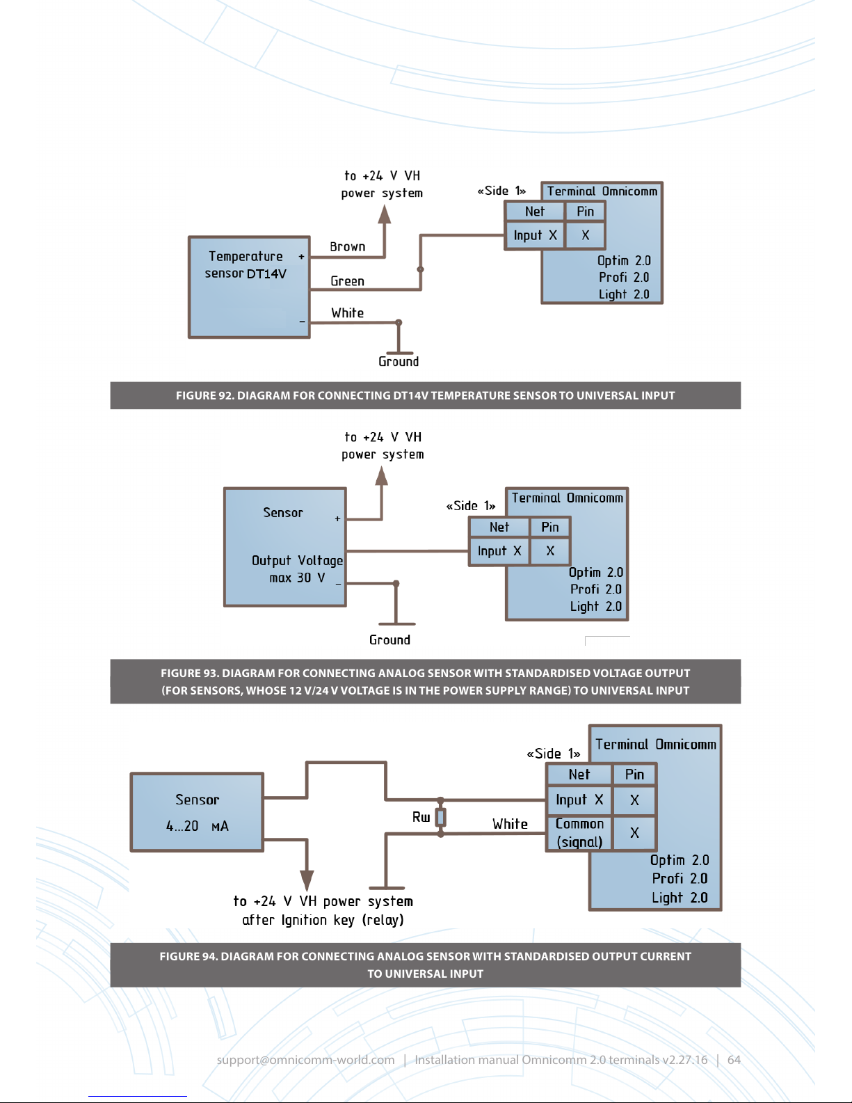
FIGURE 92. DIAGRAM FOR CONNECTING DT14V TEMPERATURE SENSOR TO UNIVERSAL INPUT
FIGURE 93. DIAGRAM FOR CONNECTING ANALOG SENSOR WITH STANDARDISED VOLTAGE OUTPUT
(FOR SENSORS, WHOSE 12 V/24 V VOLTAGE IS IN THE POWER SUPPLY RANGE) TO UNIVERSAL INPUT
FIGURE 94. DIAGRAM FOR CONNECTING ANALOG SENSOR WITH STANDARDISED OUTPUT CURRENT
TO UNIVERSAL INPUT
Page 65
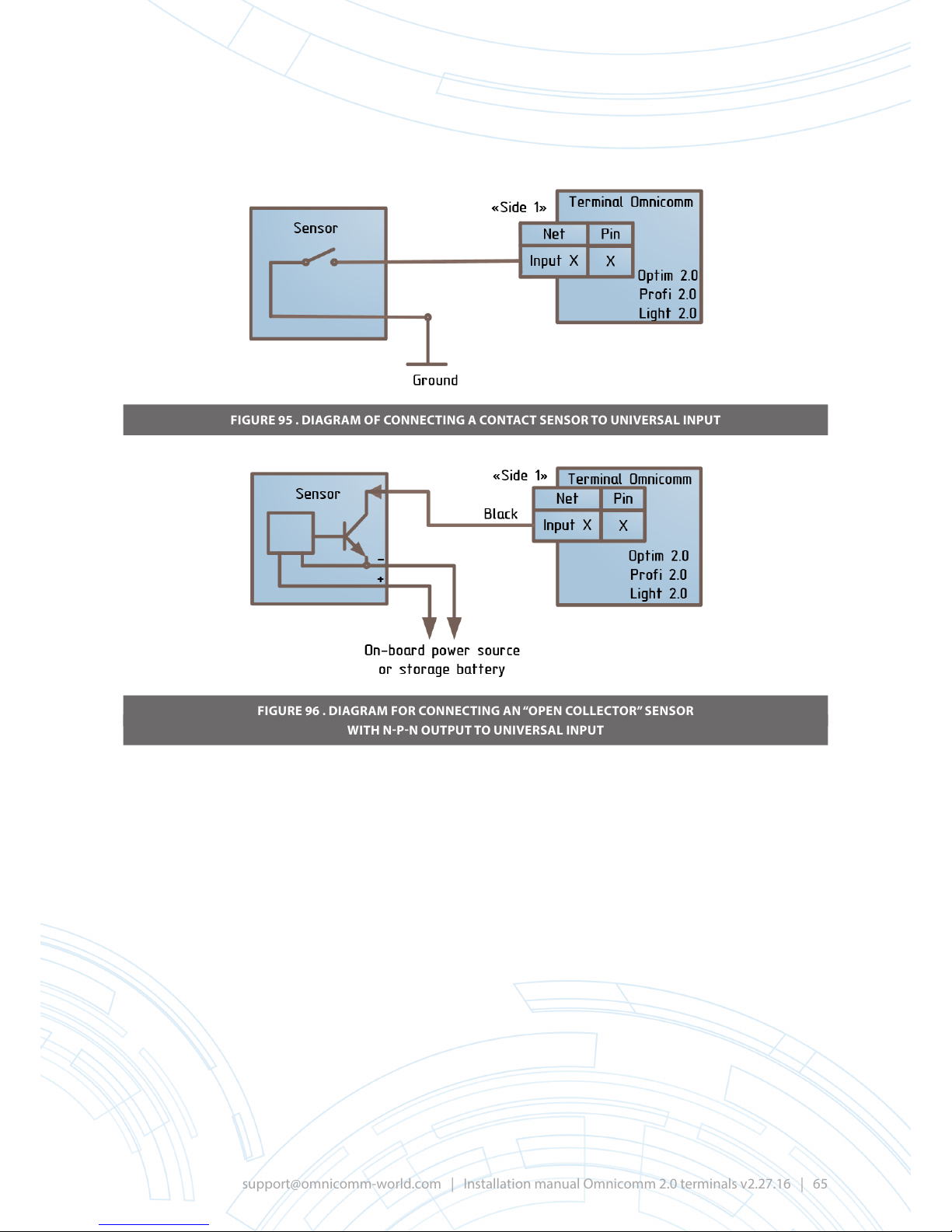
FIGURE 95 . DIAGRAM OF CONNECTING A CONTACT SENSOR TO UNIVERSAL INPUT
FIGURE 96 . DIAGRAM FOR CONNECTING AN “OPEN COLLECTOR” SENSOR
WITH N-P-N OUTPUT TO UNIVERSAL INPUT
Page 66

APPENDIX H
Conguring Omnicomm Pro and Pro 2.0 Terminals for installation at fuel stations
In order to install Omnicomm Pro and Pro 2.0 Terminals, it is necessary:
To connect signal removal device (SRD) to the rst universal input of Omnicomm Pro or Pro 2.0
Terminal.
Signal removal device (SRD) must be installed at fuel stations, equipped with motor fuel dispensing
counters manufactured by JSC “Prompribor” (Livny City).
Signal removal devices (SRD), supplied by Omnicomm, are signal removal devices SRD-B-70, manufactured
by JSC “Prompribor” and additionally equipped with connectors.
Signal removal devices SRD-B-70 can be purchased directly from the manufacturer or previously installed
SRD can be used. It is, however, necessary to observe the requirements for using of a connection cable
between the signal removal device (SRD) and the Terminal.
Attention! When installing Omnicomm Pro or Pro 2.0 terminal at fuel stations, it is necessary to connect
the power supply via the module of galvanic isolation, for example, via Omnicomm BR-15 (Figure 65).
Set the mode of the rst universal input as “impulse” and enter the calibration coecient value
Select “Impulse” operating mode in the “Inputs” section of Omnicomm Congurator.
FIGURE 97
Enter the value of calibration coecient, depending on the model of Signal Removal Device and fuel meter
according to Table 3.
Page 67
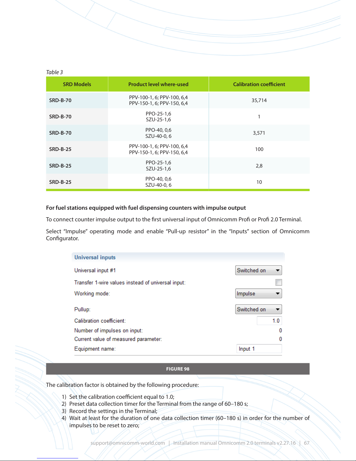
Table 3
SRD Models Product level where-used Calibration coecient
SRD-B-70
PPV-100-1, 6; PPV-100, 6,4
PPV-150-1, 6; PPV-150, 6,4
35,714
SRD-B-70
PPO-25-1,6
SZU-25-1,6
1
SRD-B-70
PPO-40, 0,6
SZU-40-0, 6
3,571
SRD-B-25
PPV-100-1, 6; PPV-100, 6,4
PPV-150-1, 6; PPV-150, 6,4
100
SRD-B-25
PPO-25-1,6
SZU-25-1,6
2,8
SRD-B-25
PPO-40, 0,6
SZU-40-0, 6
10
For fuel stations equipped with fuel dispensing counters with impulse output
To connect counter impulse output to the rst universal input of Omnicomm Pro or Pro 2.0 Terminal.
Select “Impulse” operating mode and enable “Pull-up resistor” in the “Inputs” section of Omnicomm
Congurator.
FIGURE 98
The calibration factor is obtained by the following procedure:
1) Set the calibration coecient equal to 1.0;
2) Preset data collection timer for the Terminal from the range of 60–180 s;
3) Record the settings in the Terminal;
4) Wait at least for the duration of one data collection timer (60–180 s) in order for the number of
impulses to be reset to zero;
Page 68

5) Dispense 10–20 l of fuel, and record the exact amount of dispensed fuel;
Important! The entire volume of the fuel must be dispensed within the interval of a single data collection
timer. If unsuccessful, the data collection timer duration interval must be increased.
6) Record the number of impulses counted by the Terminal during the fuel dispensing process,
which is displayed in the “Current value at input” eld upon expiration of data collection timer
duration interval;
7) Calculate calibration coecient K using the following formula:
8) Set the desired timer data collection and the calibration coecient, then record the settings in
the Terminal.
REVISION HISTORY
DATE VERSION DESCRIPTION
11.02.16 1.16 Initial Release
27.07.16 2_24.16 Update
 Loading...