

Page 1

Omnicomm 3.0 Terminals
User Manual
Omnicomm Configurator 6
30.09.2019
Profi, Profi Wi-Fi, Optim, Smart
Page 2

Contents
General information
5
Attention
5
Installation
6
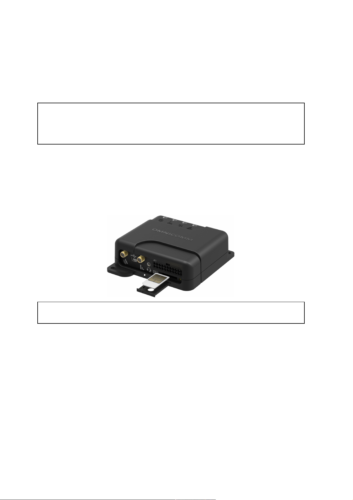
SIM Card Inserting
6
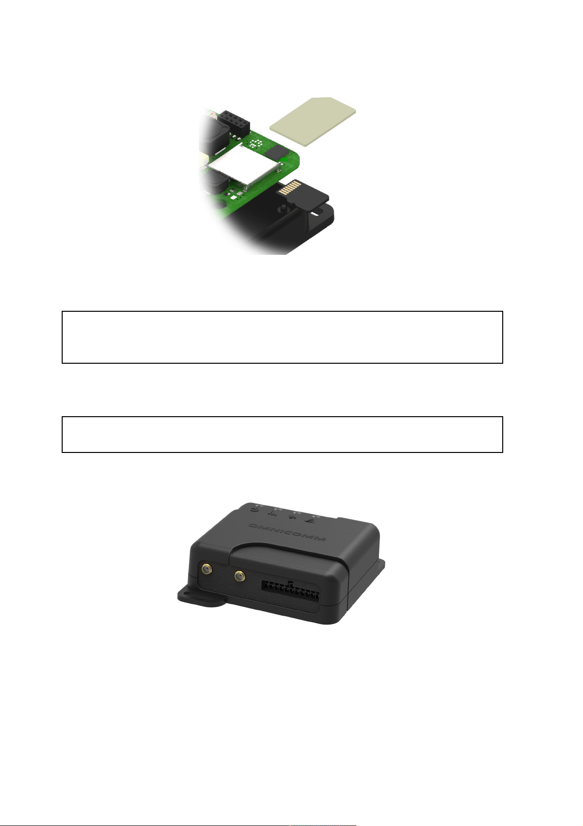
Second SIM Card and SD Card Inserting for Optim
6
Protective Insert Placing for Optim
7
Connector Pin Assignment
8
Power Supply and Ignition Key
15
Terminal
19
Antennas
21
Setting Overview
22
Omnicomm Configurator
22
Remote Configuration Server (RCS)
24
Operation Parameters Setting
24
GPRS connection
24
Wi-Fi Data Transmission
25
Connection to Communication Servers
26
Data Collection
27
Data Transmission to the Communication Server
29
Selection of Ignition Source
30
Selection of Speed Source
31
Engine RPM
31
Page 3

Driving Safety Control
32
Body Tampering Control
37
Internal Battery
37
GPS / GLONASS Signal Jamming Detector
38
GSM Signal Jamming Detector
38
Service Functions
39
Terminal Reboot
39
Setting Password on Configuration Changing
39
Data Collection and Transmission Blocking
40
Remote Configuration Server Operation Setting
41
Terminal SIM Card Number Identification
41
Additional Equipment
41
RS-485 and RS-232 Interfaces
41
Fuel Level Sensors
44
Omnicomm ICON Display
47
Omnicomm LLD Indicator
50
Tachograph
51
Universal Inputs
51
Driver Identification
55
Temperature Sensor
59
Voice Communication
59
RFID Reader Connection
61
Controlled Equipment
61
Geofences Setting
63
Panic Button and GSM Call Button
64
Page 4

CAN Bus
65
Specifications
68
LED and Sound Notification
71
SMS from the Terminal
75
SMS Commands
76
Firmware Change Log
80
Page 5

Omnicomm 3.0 Terminals
Profi, Profi Wi-Fi, Optim, Smart
General information
Omnicomm terminals – vehicle equipment designed to gather information on the
vehicle parameters and transmit data to Omnicomm Online or a third-party fleet
monitoring system (except Smart, Smart Promo).
Main functions:
Determination of location, speed and movement direction of vehicle
Reading and filtering values from fuel level sensors and a wide range of connected
equipment
Data storage in non-volatile memory
Data transmission to Omnicomm Online and other transport monitoring systems
(except Smart, Smart Promo).
Models of Omnicomm terminal differ from each other in the design and range of
connected equipment.
Attention
While carrying out installation, observe the safety rules and regulatory requirements
for this type of work.
General information
5
Page 6
Installation
SIM Card Inserting
Before SIM card inserting disable PIN request at activation. For this end insert the card
in any cell phone and disable PIN request, according to the cell phone operating
instruction.
1. Using a sharp-pointed object press the button on the terminal front panel. The
SIM card holder will eject
2. Remove the SIM card holder from the connector slots and insert the SIM card into
it with contact pieces up
3. Insert the SIM card holder in the connector slots:
SIM chip installation is available under custom order.
Second SIM Card and SD Card Inserting for Optim
1. Unscrew the two screws fixing the terminal body
2. Remove the upper body part
3. Insert a miniSD card in the slot intended for SD card
4. Insert the second SIM card in the slot as shown in figure:
Installation
6
Page 7
Protective Insert Placing for Optim
The protective insert is placed after SIM cards inserting, setting the terminal and
before the connection of mounting cable connector and antennas.
1. Remove protective film from the insert
2. Carefully install the protective insert in the terminal body
Reinstallation of the protective insert is not possible
3. Treat the mounting cable connector wire exit points with silicone sealant or hot-
melt glue
Installation
7
Page 8
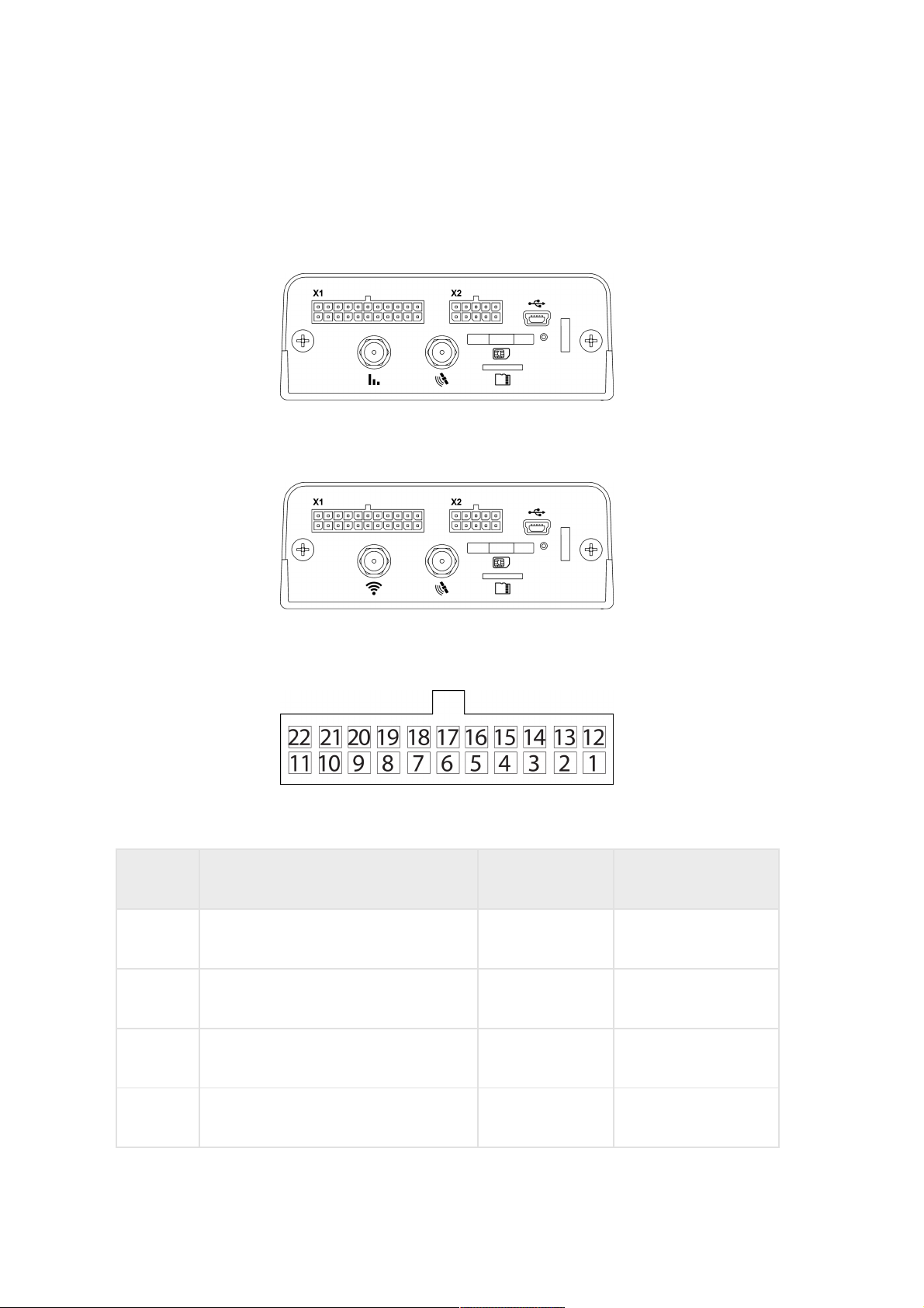
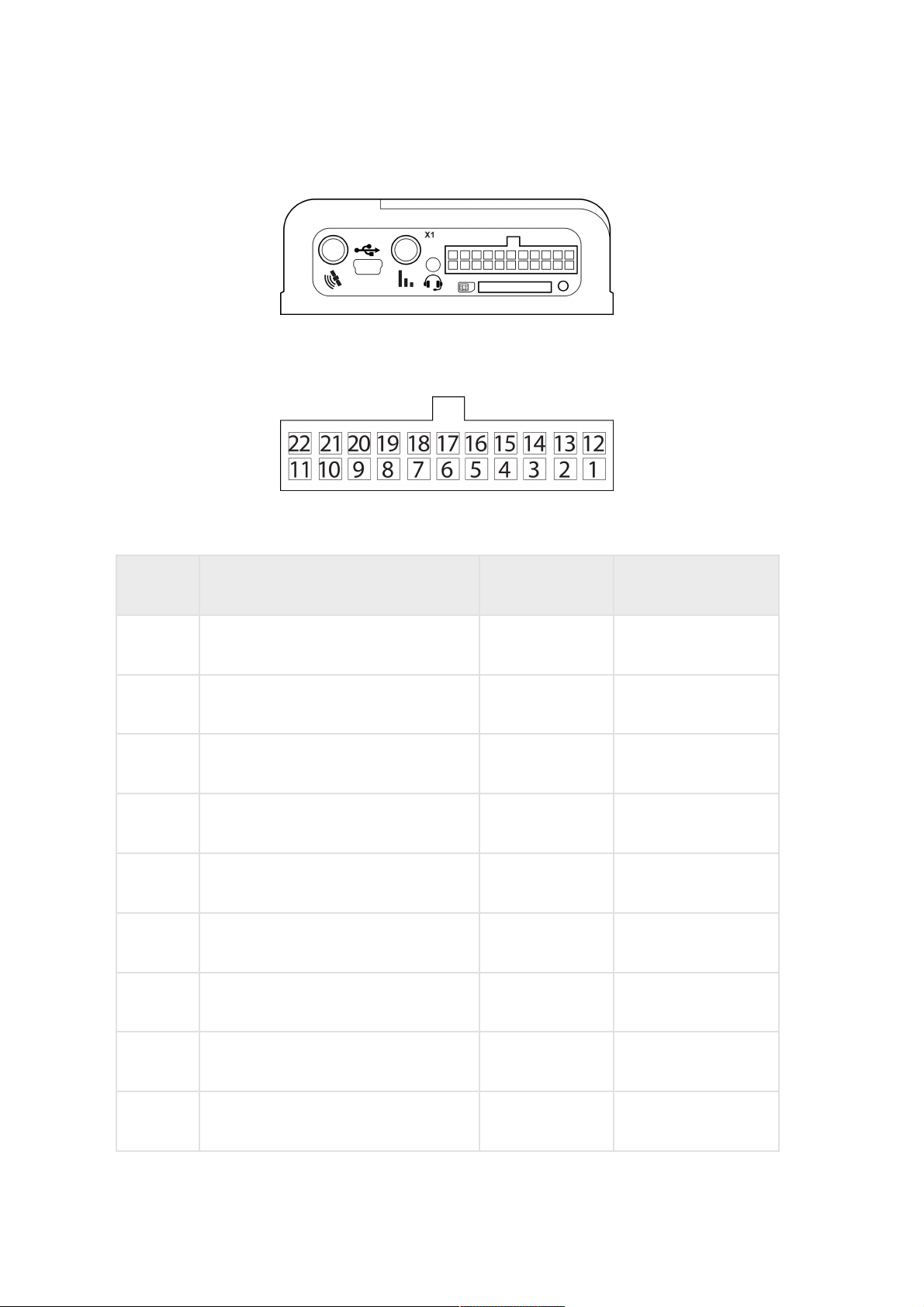
Connector Pin Assignment
Omnicomm Profi terminals:
Omnicomm Profi Wi-Fi terminals:
Connector Х1:
No. of pin Signal name Designation Wire colour in cable
1 Ground (negative) for power supply Ground (signal) White
2 Ground (negative) for power supply Ground (power) White
3 Panic button Panic button White-red
4 Universal input 2 Input 2 Black-white
Installation
8
Page 9

5 Universal input 4 Input 4 Black-yellow
6 RPM input Tachometer Blue
7 Controlled output 2 Output 2 Yellow-dark blue
8 Line RX RS-232 RS-232 RX Pink
9 Line B RS-485 №2 B RS-485 №2 Black-blue
10 Line B RS-485 №1 B RS-485 №1 Blue-white
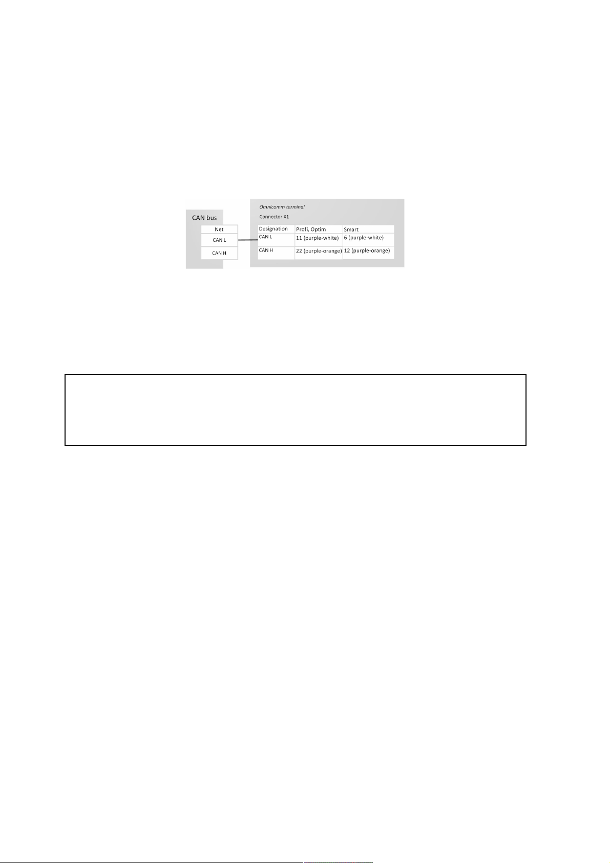
11 CAN L CAN L Purple-white
12 Vehicle power supply voltage Power (positive) Red
13 Ignition key IGN Yellow
14 GSM Activation Button GSM Green-black
15 Universal input 1 Input 1 Black
16 Universal input 3 Input 3 Black-red
17 iButton+ iButton+ Pink-red
18 Controlled output 1 Output 1 Yellow-red
19 Line TX RS-232 RS-232 TX Grey
20 Line A RS-485 №2 A RS-485 №2 White-green
No. of pin Signal name Designation Wire colour in cable
Installation
9
Page 10
21 Line A RS-485 №1 A RS-485 №1 Orange-white
22 CAN Н CAN Н Purple-orange
No. of pin Signal name Designation Wire colour in cable
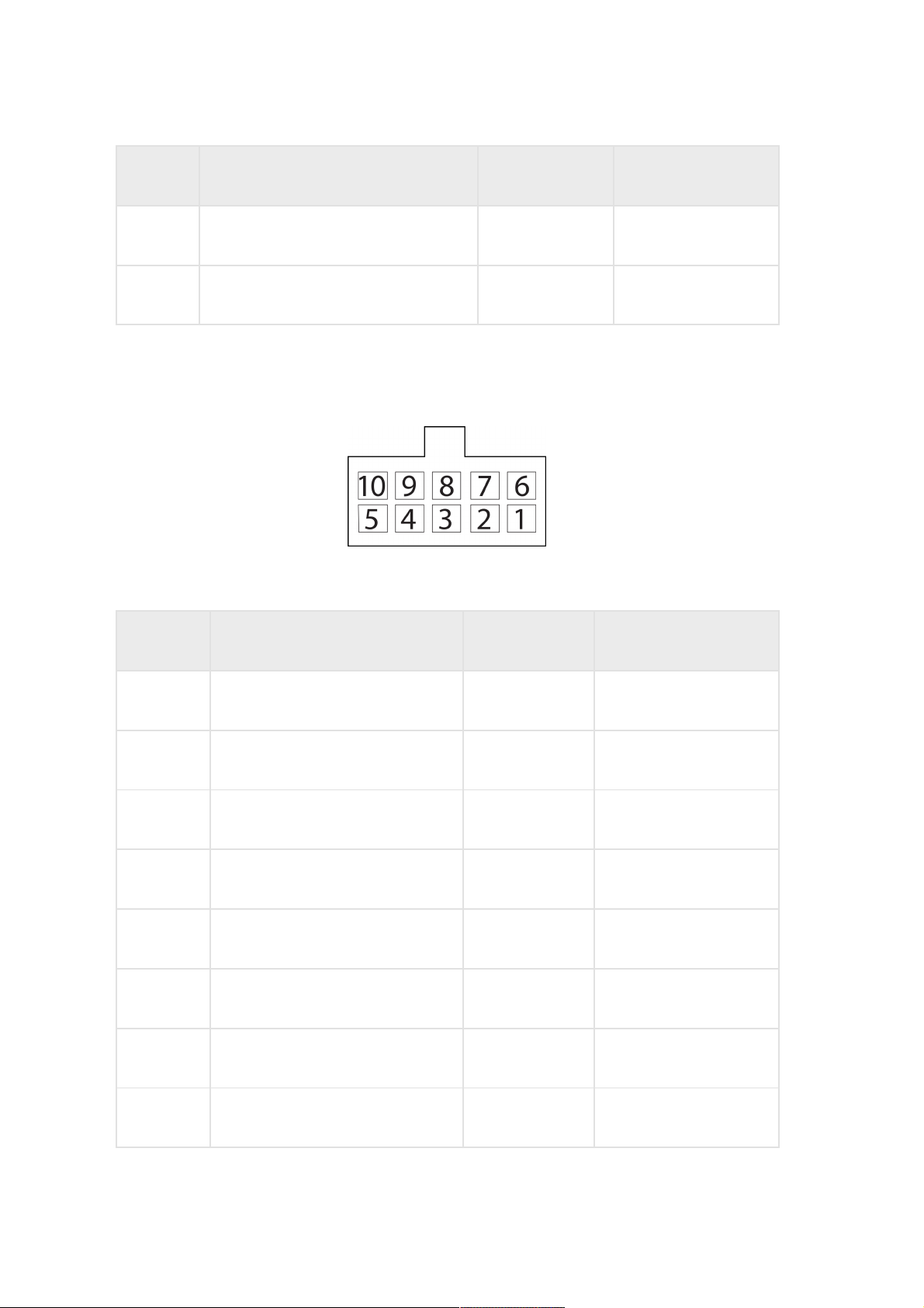
Connector Х2:
No. of pin Signal name Designation Wire colour in cable
1 Microphone- Microphone- Green-yellow
2 Speaker- Speaker- Grey-yellow
3 Ground GND White
4 Universal input 5 Input 5 Green
5 Ground GND White
6 Microphone+ Microphone+ Green-red
7 Speaker+ Speaker+ Grey-red
8 iButton- iButton- Pink-blue
Installation
10
Page 11

9 Universal input 6 Input 6 Purple
10 Plus LLS sensor power supply PWR LLS Brown
No. of pin Signal name Designation Wire colour in cable
Installation
11
Page 12
Omnicomm Optim terminal
Connector Х1:
No. of pin Signal name Designation Wire colour in cable
1 Ground (negative) for power supply Ground (signal) White
2 Ground (negative) for power supply Ground (power) White
3 Panic button Panic button White-red
4 Universal input 2 Input 2 Black-white
5 Universal input 4 Input 4 Black-yellow
6 RPM input Tachometer Blue
7 Controlled output 2 Output 2 Yellow-dark blue
8 Line RX RS-232 RS-232 RX Pink
9 Line B RS-485 №2 B RS-485 №2 Black-blue
Installation
12
Page 13

10 Line B RS-485 №1 B RS-485 №1 Blue-white
11 CAN L CAN L Purple-white
12 Vehicle power supply voltage Power Red
13 Ignition key IGN Yellow
14 GSM Activation Button GSM GSM Green-black
15 Universal input 1 Input 1 Black
16 Universal input 3 Input 3 Black-red
17 iButton+ iButton+ Pink-red
18 Controlled output 1 Output 1 Yellow-red
19 Line TX RS-232 RS-232 TX Grey
20 Line A RS-485 №2 A RS-485 №2 White-green
21 Line A RS-485 №1 A RS-485 №1 Orange-white
22 CAN Н CAN Н Purple-orange
No. of pin Signal name Designation Wire colour in cable
Omnicomm Smart terminal
Installation
13
Page 14
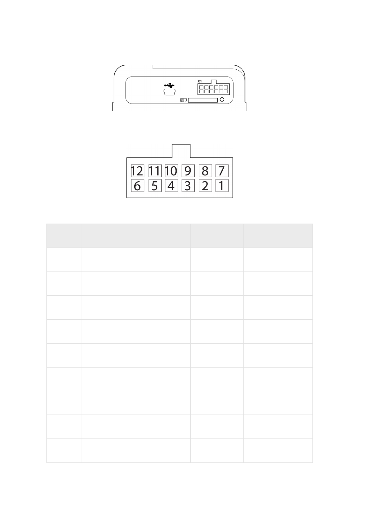
Connector Х1:
No. of pin Signal name Designation Wire colour in cable
1 Ground (minus) for power supply Ground (signal) White
2 RPM input Tachometer Dark blue
3 Not used NC
4 Not used NC
5 Line B RS-485 LLS B RS-485 LLS Blue-white
6 CAN L CAN L Purple-white
7 Vehicle power supply voltage Power Red
8 Ignition key IGN Yellow
9 Universal input 1 Input 1 Black
Installation
14
Page 15
10 Not used NC
11 Line A RS-485 LLS A RS-485 LLS Orange-white
12 CAN Н CAN Н Purple-orange
No. of pin Signal name Designation Wire colour in cable
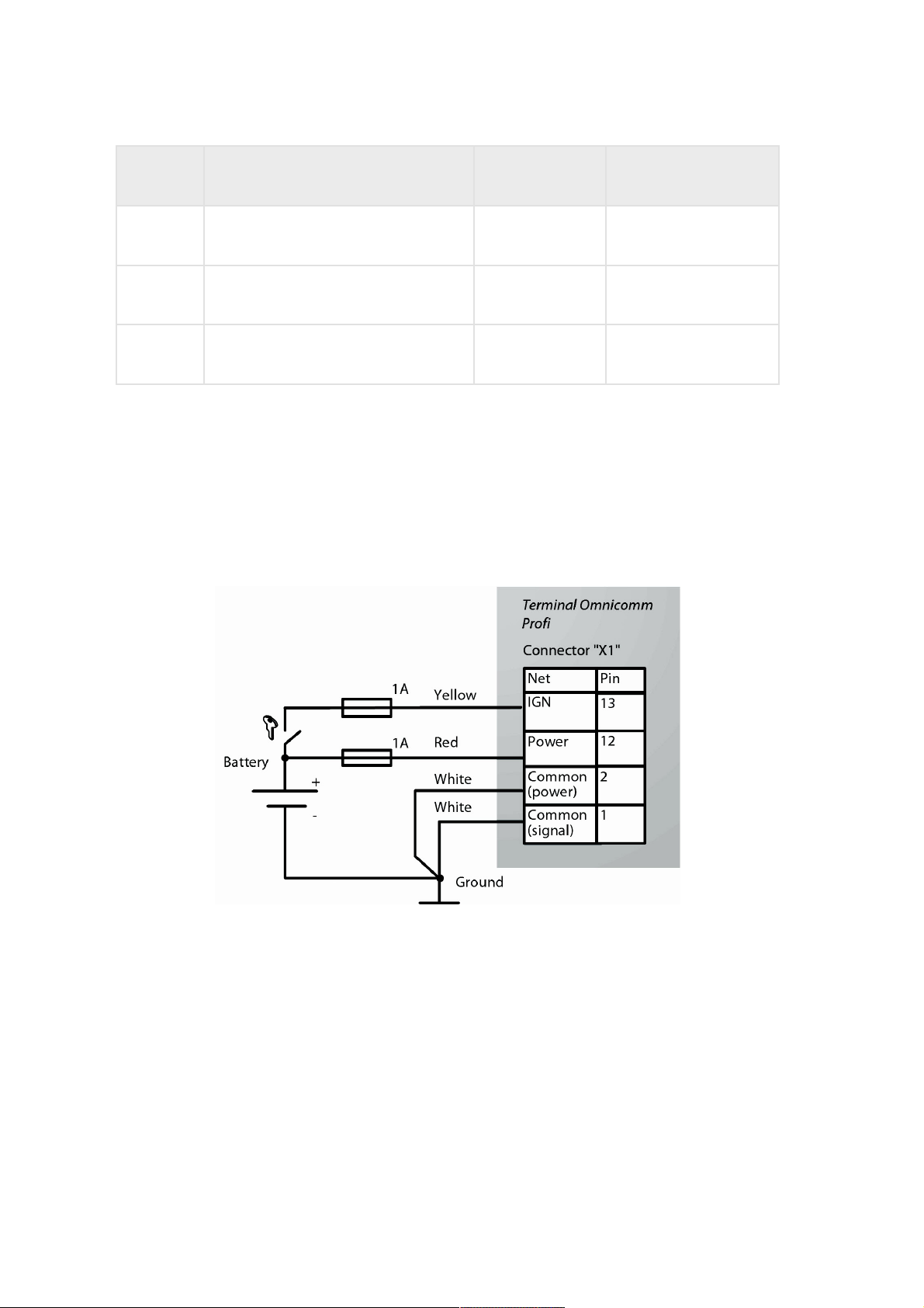
Power Supply and Ignition Key
Connect Omnicomm Profi, Profi Wi-Fi terminals as per diagrams without battery
disconnect switch:
Installation
15
Page 16
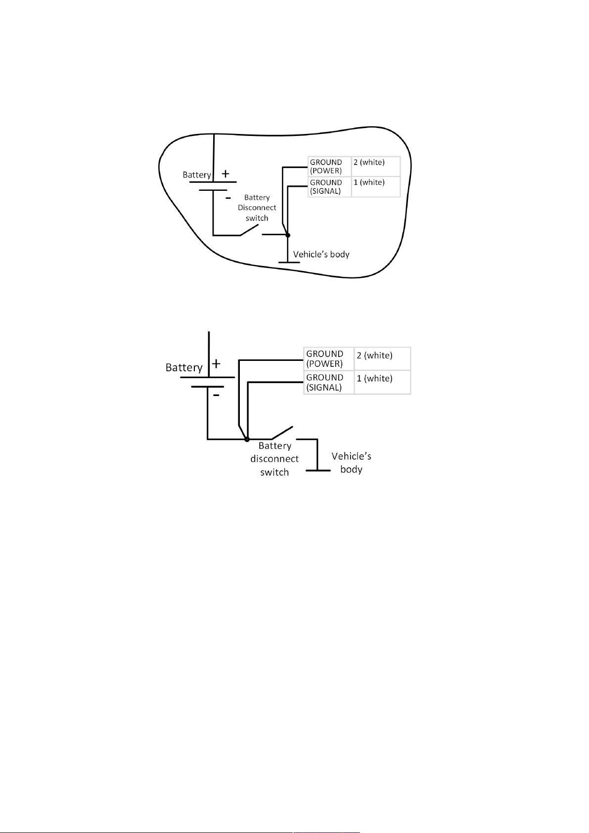
after ground disconnect switch:
before ground disconnect switch:
Installation
16
Page 17
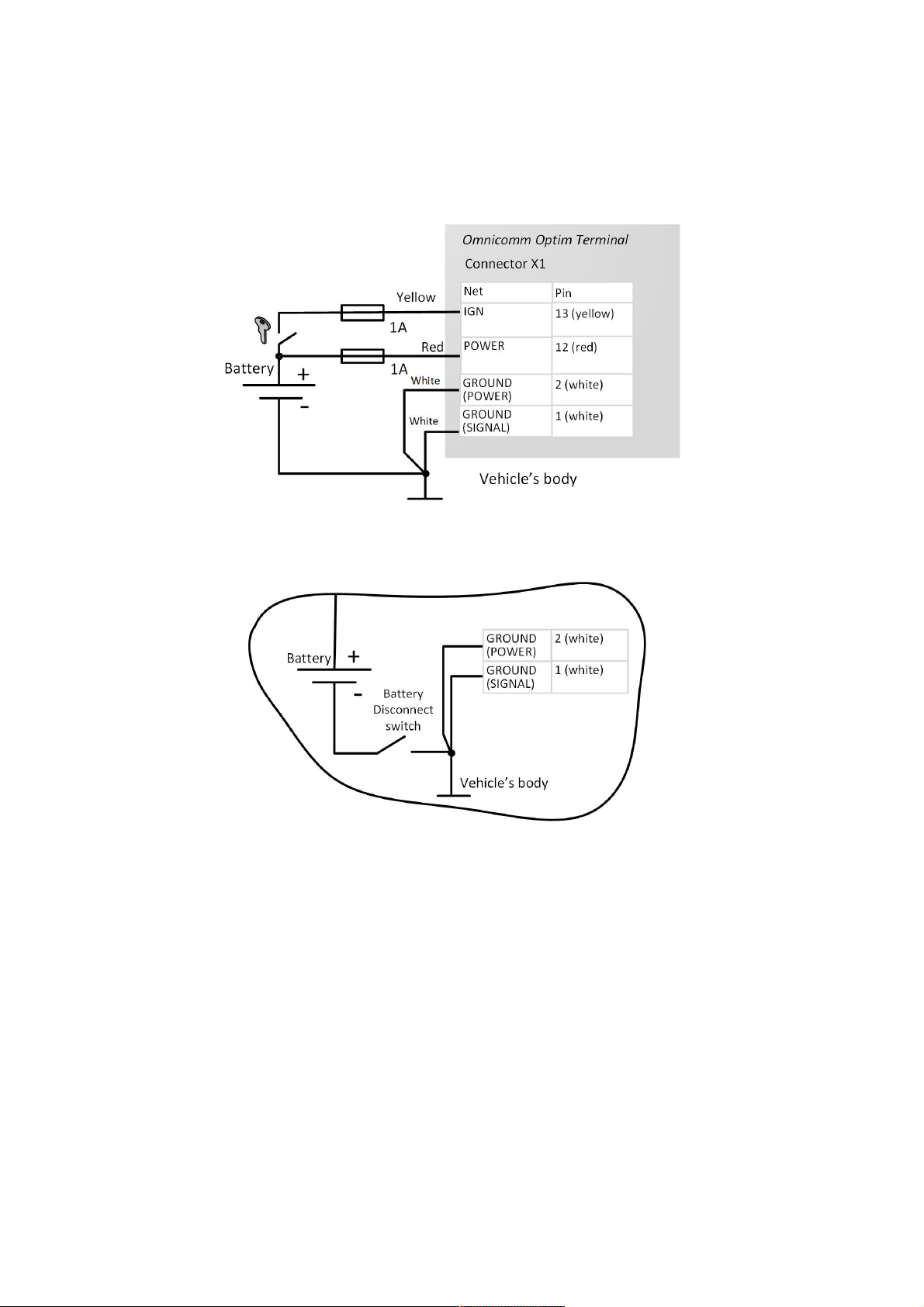
Connect Omnicomm Optim terminals as per diagrams without ground disconnect
switch:
after ground disconnect switch:
Installation
17
Page 18
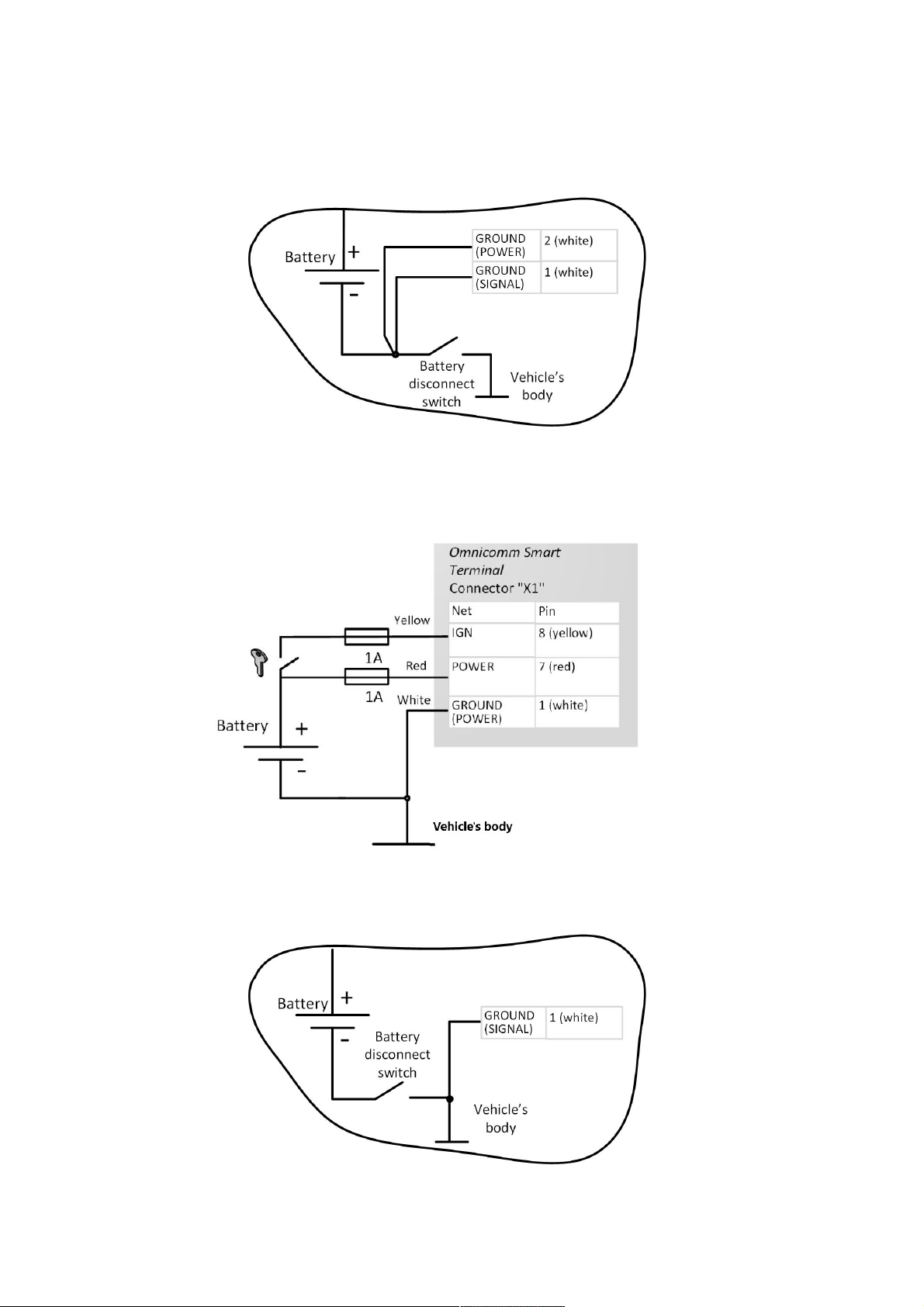
before ground disconnect switch:
Connect Omnicomm Smart terminals as per diagrams without ground disconnect
switch:
after ground disconnect switch:
Installation
18
Page 19
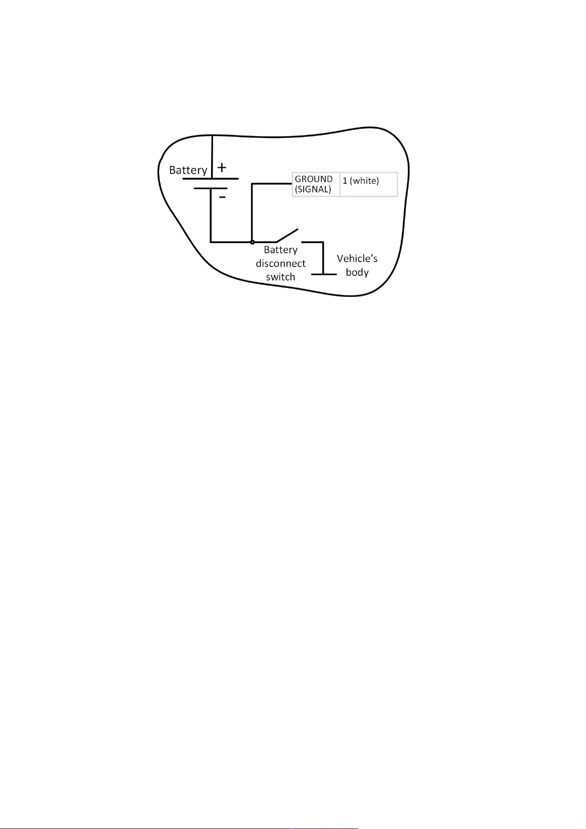
before ground disconnect switch:
Terminal
Omnicomm terminal shall be installed in the vehicle cabin or in specially equipped
electrics boxes on the vehicle protected from atmospheric precipitation.
Drill 4 mounting holes Ø4 mm.
For Omnicomm Profi, Profi Wi-Fi terminals:
Installation
19
Page 20
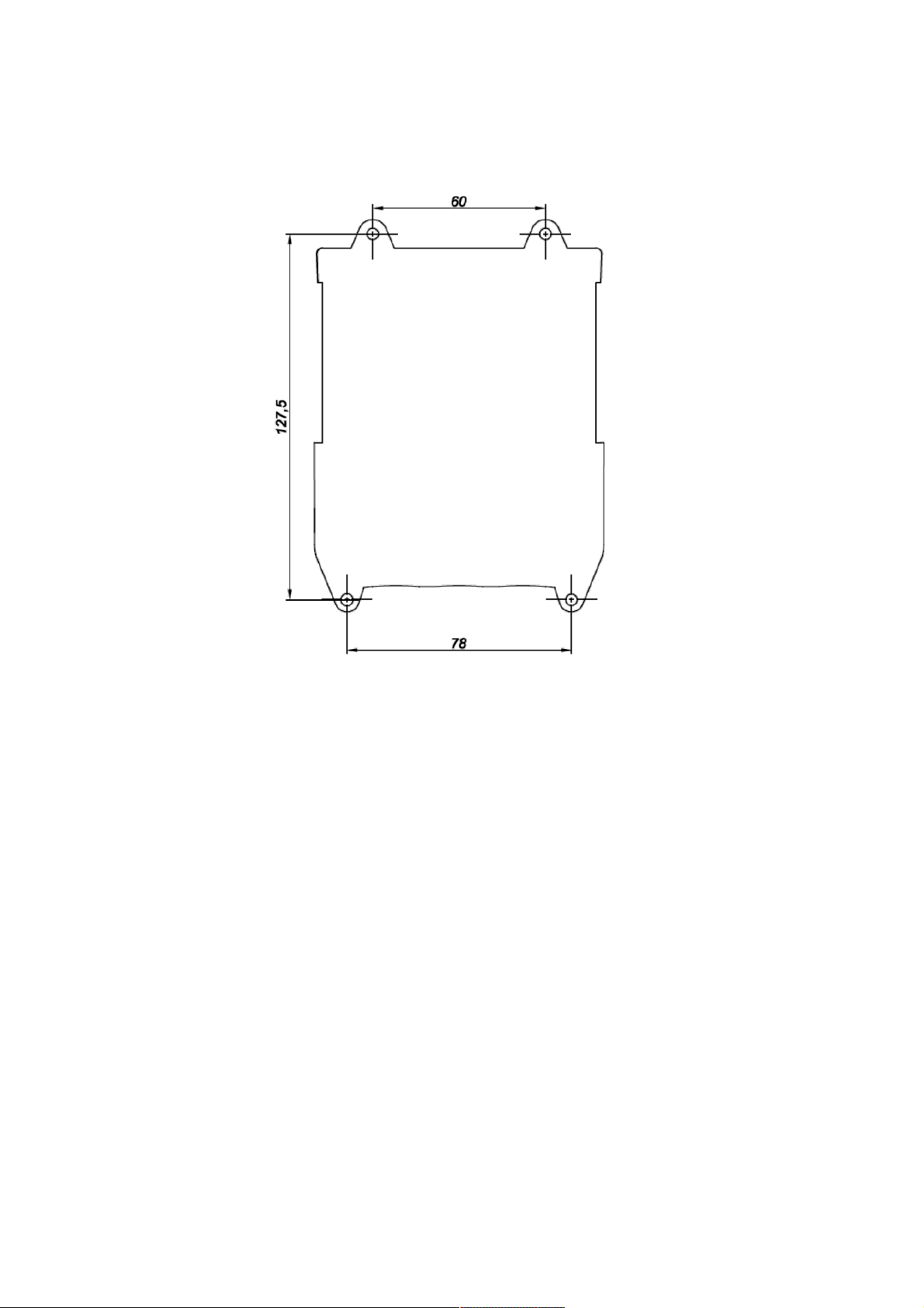
For Omnicomm Optim and Smart terminals:
Installation
20
Page 21
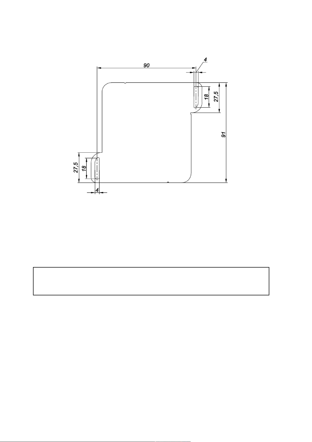
Install the terminal and fix with self-tapping screws.
Antennas
Choose the installation site of antennas based on the antenna cable length.
Antennas should be installed inside the vehicle cabin on a flat surface.
Distance from antennas to any metal surface (except for the surface of installation)
should be not less than 50 mm.
Recommended installation site of antennas: vehicle windshield or inner side of the
vehicle plastic front panel.
1. Degrease the installation site surface
2. Remove protective film from the double adhesive tape on the surface of antenna
3. Attach the antenna with the adhesive side to the installation site
4. Fix the antenna while the adhesive is setting
Installation
21
Page 22
Setting Overview
Omnicomm terminals may be configured in two ways:
1. In the Omnicomm Configurator when the terminal is connected to a PC
2. In the Remote Configuration Server (RCS) – remotely
Initial terminal setting shall be carried out in Omnicomm Configurator.
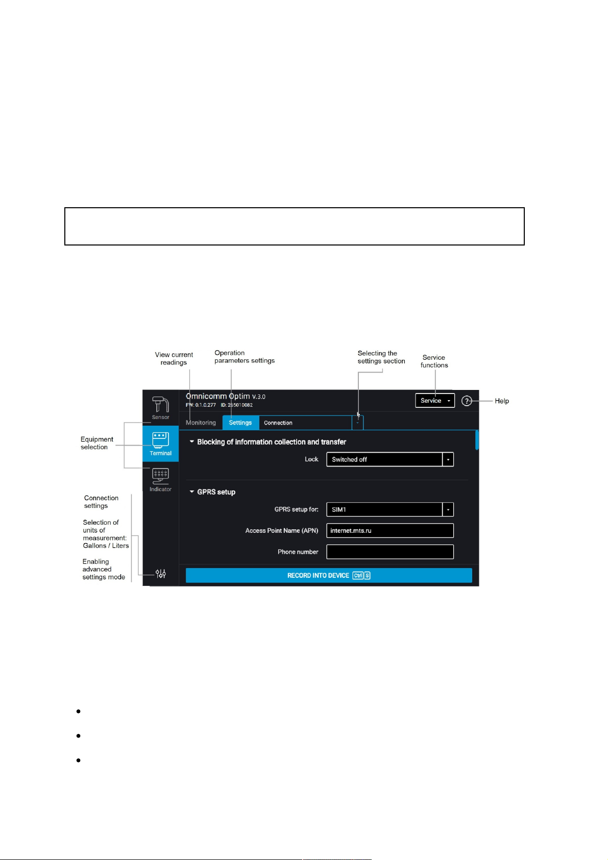
Omnicomm Configurator
1. Connection the terminal to a PC using USB cable
2. Install and run Omnicomm Configurator. A window will open:
3. Select equipment – “Terminal”.
Advanced mode allows you to configure all the equipment parameters available.
List of parameters shown in advanced mode only:
In the “Communication” section:
Data collection and transmission blocking
EGTS protocol settings
Communication Server No. 2 connection settings
Setting Overview
22
Page 23

GSM and SMS communication parameters
Roaming connection parameters
Roaming parameters
In the “RS-485 and RS-232 Interfaces Configuration” section:
«CAN-log»
«J1708»
«NMEA reception»
«NMEA transmission»
«PP-01»
«Camera»
«DV-01»
«Tachograph VDO»
«iQFreeze»
«TPMS Pressure Pro»
«ALM Weight Indicator»
«Carrier Reefer»
In the “Auxiliary equipment” section:
Panic button parameters
Accelerometer parameters
Sections “Universal inputs”, “CAN”, “Identification”, “Geofences”, “Outputs”, “Driving
Control”.
Setting Overview
23
Page 24
Remote Configuration Server (RCS)
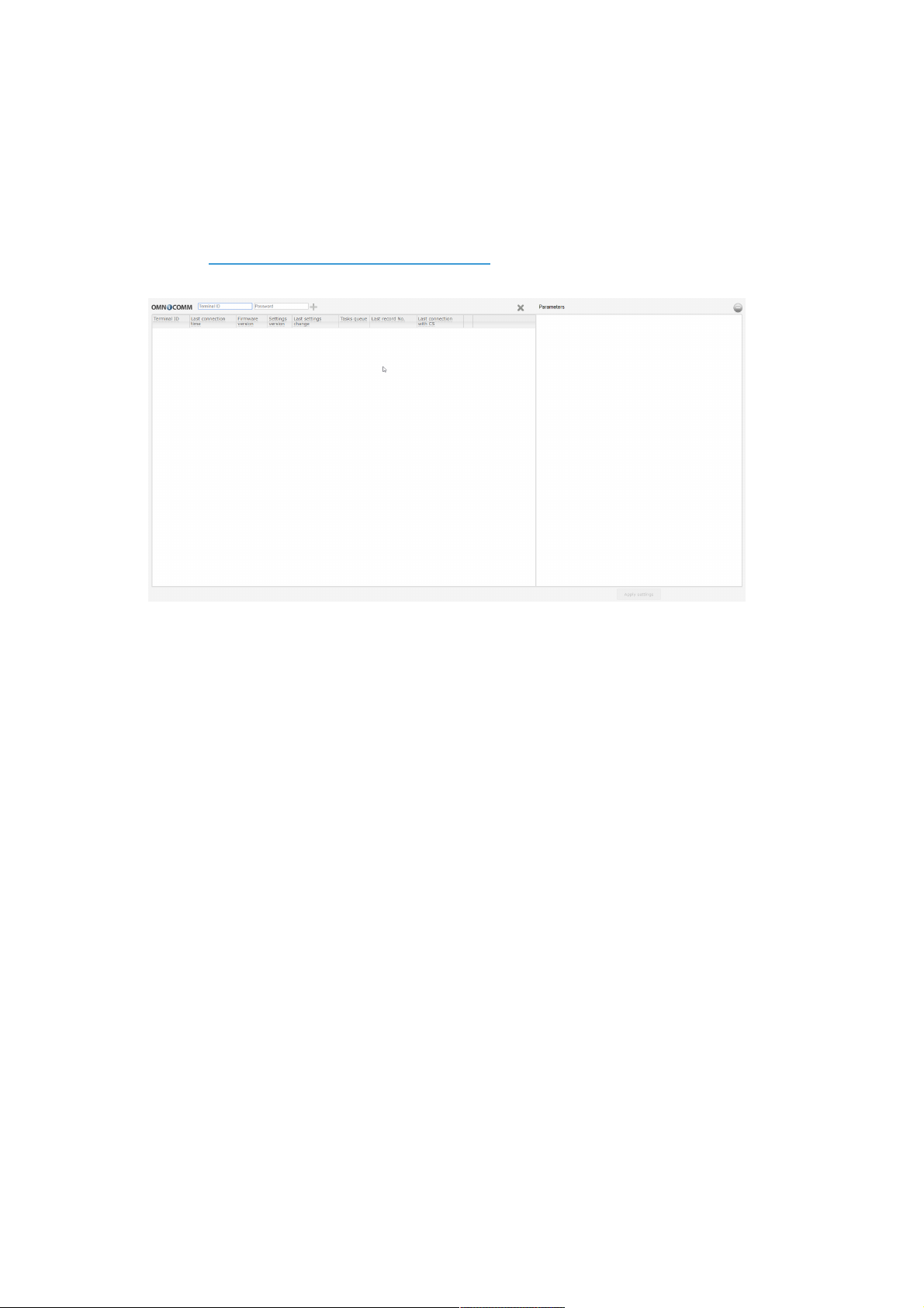
To connect to the configuration server, open the browser and in its address bar enter
the address http://config.omnicomm.ru:9911/#en. A window will open:
To add terminals:
1. In the “Terminal ID” field enter the terminal identification number
2. In the “Password” field enter the password set in the terminal during its setting
using Omnicomm Configurator program
3. Press the “+” button
Operation Parameters Setting
GPRS connection
In the «Settings» tab select the «Connection» section from the list.
In the «GPRS Setup» section:
Operation Parameters Setting
24
Page 25
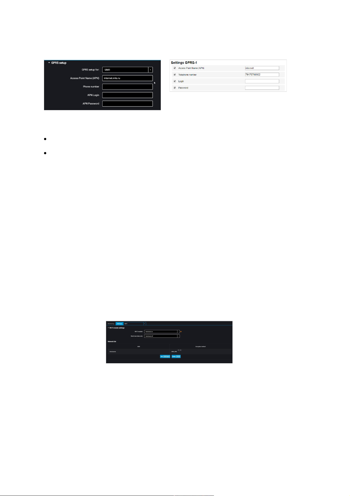
For Optim and Profi, Profi Wi-Fi choose the SIM card to perform setting:
SIM 1 – external SIM card
SIM 2 – internal SIM card / SIM chip for Omnicomm Optim or SIM chip for
Omnicomm Profi, Profi Wi-Fi
For GPRS access point names of other operators, refer to the mobile network operator,
whose SIM card is inserted in the terminal.
“Phone number” – number of the SIM card inserted in the terminal.
“APN Login” and “APN Password” – if necessary, enter login and password for APN
access point. Login and password are provided with the SIM card of a number of
mobile network operators.
Wi-Fi Data Transmission
Omnicomm Configurator provides the Omnicomm Profi Wi-Fi terminal with Wi-Fi
wireless network data transmission setting option.
In the “Settings” tab select the “Wi-Fi” section from the list.
In the “Wi-Fi module settings” section:
“Wi-Fi module” – enable/disable data transmission via Wi-Fi wireless network.
“Send only non-transmitted data” – enable/disable data duplication when using
multiple Local communication servers. When the parameter is enabled, the data
transmitted to one LCS will not be transmitted to other LCS operating on the same IPaddress.
“SSID” – enter the access point name specified when configuring the Wi-Fi base
station
Operation Parameters Setting
25
Page 26
“Authentication and Encryption Method” – select the data authentication and
encryption method used in the Wi-Fi base station.
Possible options:
«Open» – encryption is not used
«WPA_PSK»
«WPA_EAP (FAST)
«WPA_EAP (PEAP)
When using encryption, specify “Login” and “Password” to connect to the Wi-Fi base
station.
Press the “Add” button.
The “List of networks” section displays Wi-Fi access points, which the terminal can use
for Wi-Fi wireless network data transmission.
To connect the terminal to a hidden Wi-Fi network, during the setting specify only
one Wi-Fi access point.
Connection to Communication Servers
Terminals support data transmission to two Communication Servers (CS) through
Omnicomm and EGTS protocols.
In the “Settings” tab select the “Сonnection” section from the list.
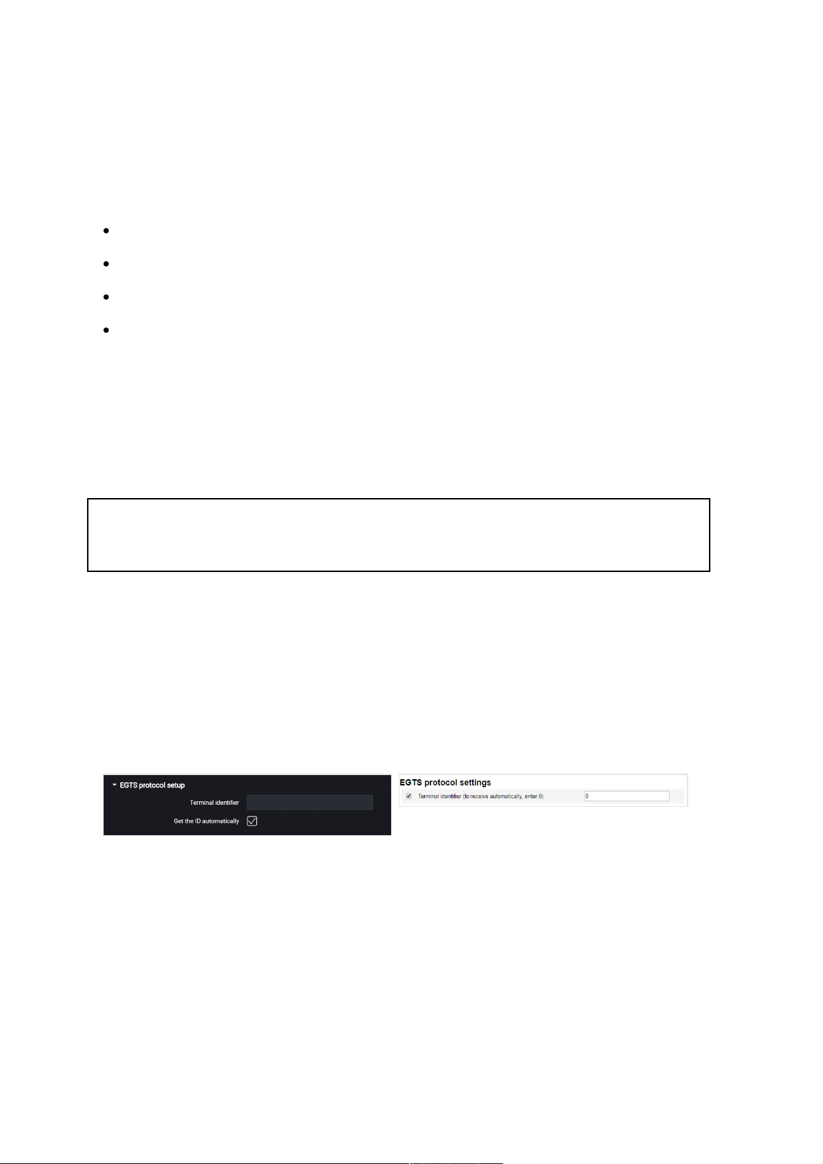
In the “EGTS Protocol setup” section:
When setting up EGTS data transmission, you must use the TID terminal identification.
If the settings are not configured, when transmitting data through EGTS protocol ID
Omnicomm will be used for terminal identification.
In the “Settings of connection to the communication server” sections:
Operation Parameters Setting
26
Page 27
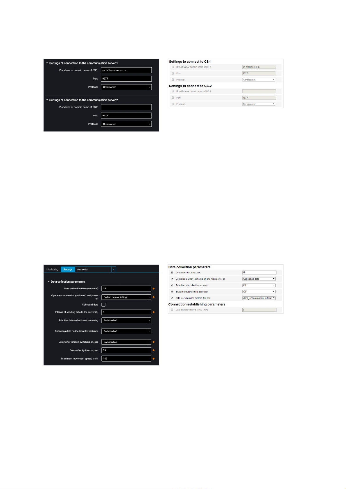
“IP address or domain name of CS” – enter IP address or domain name of the
communication server: cs.dc1.omnicomm.ru.
“Port” – enter port to be used by terminal to connect to the communication server:
9977
“Protocol” – select data transmission protocol to the CS. Possible options: Omnicomm
or EGTS.
Data Collection
In the “Settings” tab select the “Connection” section from the list.
In the “Data collection parameters” section:
“Data collection timer (seconds)” – set the value of the period of Terminal requesting
modules and external devices connected to it. Range of values – from 15 to 240
seconds.
“Operation with ignition off and power on” select:
Operation Parameters Setting
27
Page 28

“Collect all data” – data collection and transmission same as with ignition turned
on.
“Collect all except GPS” – collection and transmission of data selected during
configuration of the terminal, except for the GPS module data
“Collect data at jolting” – monitoring the status of the panic button and
accelerometer. If the accelerometer reading changes by more than 0.2 g or the
panic button is pressed, the terminal switches to the “Collect all data” and performs
data transmission to the Communication Server in 5 minutes
When selecting “Collect data at jolting” set the following configuration:
“Collect all data” – when this parameter is enabled, the terminal upon expiration of
the time specified in the “Period of data sending to Server” switches to the “Collect
all data” mode and performs data collection and transmission to the
communication server. After the data transmission the terminal switches to the
“Collect data during pounding” mode.
“Interval of sending data to the server (h)” – the time interval between the terminal
connections to CS.
Depending on the set mode, the data are acquired from the particular modules and
external devices.
“Adaptive data collection at cornering” – enable/disable adaptive data collection on
turns, which allows increasing the accuracy of displaying turns on the map by
additional data collection from the GPS module more frequently than set in the “Data
collection” parameter.
“Collecting data on the traveled distance” – allows increasing the accuracy of
displaying the vehicle location on the map by additional data acquisition from the
GPS module over the distance traveled between the events with registered
coordinates.
“Distance traveled” – enter the mileage traveled from the moment of the last
registered event with coordinates, upon achieving which the data will be acquired.
Possible values: from 10 to 1000 meters. Default value – 100 meters.
“Coordinate drift filtering” – enable to eliminate runout of coordinates during the
“Track” report generation.
When enabling the “Coordinate drift filtering” the following settings are available:
“Delay after ignition on, sec”. Default value – 35 sec. Possible values: from 0 to 900.
Operation Parameters Setting
28
Page 29
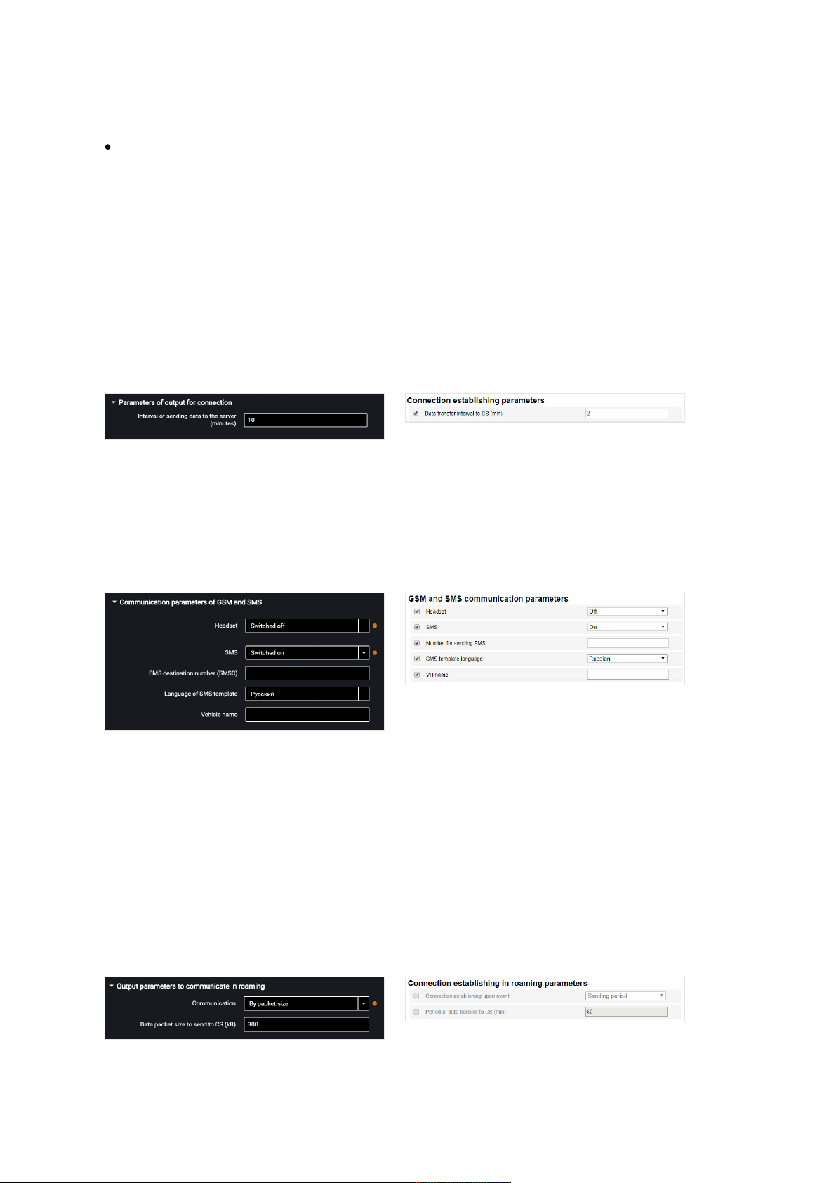
“Maximum movement speed, km/h”. Default value – 180 km/h. Possible values: from
5 to 360.
The default values allow elimination of drift for most cases and do not require
correction.
Data Transmission to the Communication Server
In the “Settings” tab select the “Connection” section from the list.
In the “Parameters of output for connection” section:
“Interval of sending data to the server” – enter the number of minutes, upon
expiration of which the terminal must establish connection with the communication
server, while being in the mobile operator's home network. Recommended value – 10
minutes.
In the “Communication parameters of GSM and SMS” section:
“SMS” – enable/disable the commands reception via SMS and sending the information
messages by the Terminal.
“SMS destination number” – enter the phone number, to which the SMS will be sent
with information about the status of the Terminal and the vehicle.
“Language of SMS template” – select the language of the SMS template. Possible
options: Russian, English, Portuguese, Spanish.
“Vehicle Name” – enter the name of the vehicle. The “Vehicle Name” field is mandatory.
In the “Output parameters to communicate in roaming” section:
Operation Parameters Setting
29
Page 30
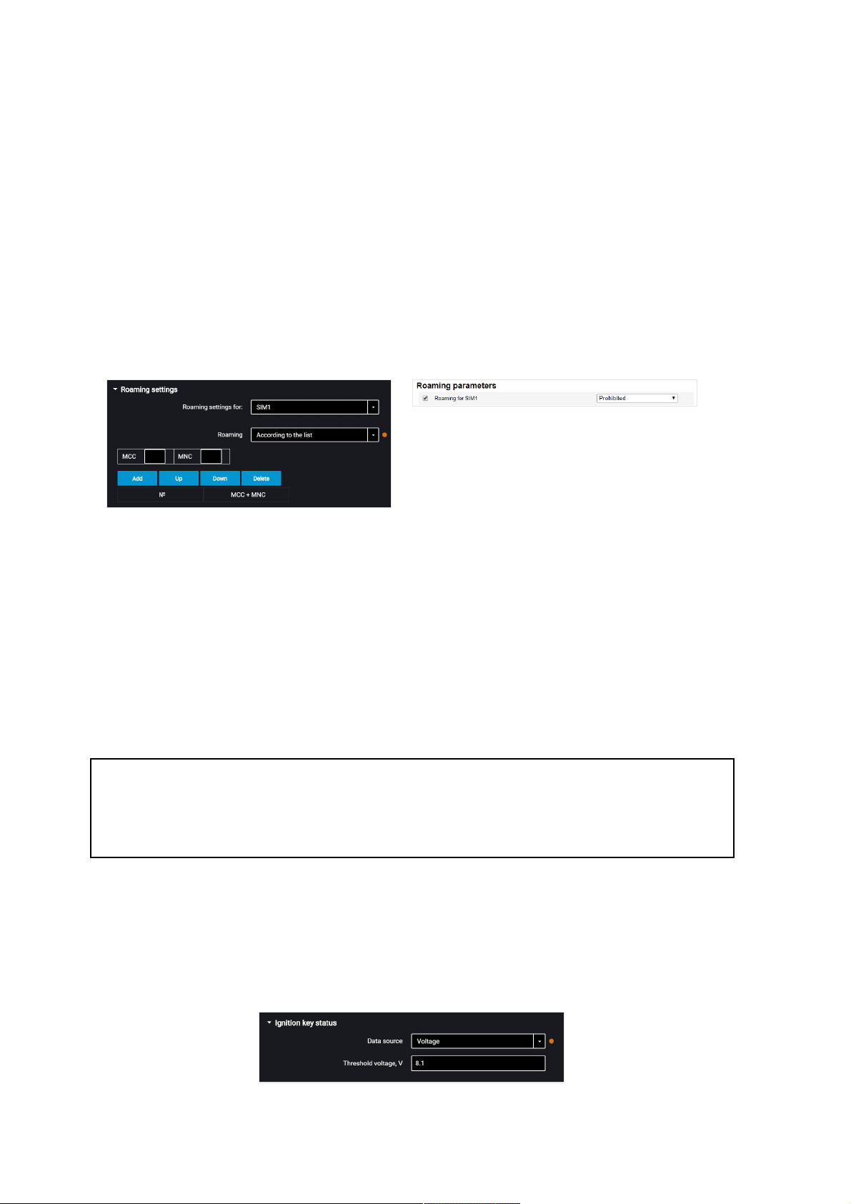
Select the criterion for the terminal connection to the CS: “Interval of sending data to
CS” or “Data package size to be sent to CS”.
“Interval of sending data to the CS” – enter the number of minutes, upon expiration
of which the terminal must establish connection with the communication server,
while being in roaming. Recommended value – 180 minutes.
“Data packet size to send to CS” – enter the data batch size, upon achieving which the
terminal must establish connection with the communication server, while being in
roaming. Recommended value – 100 Kb.
In the “Roaming settings” section:
“Roaming” – select the option of SIM card using while in roaming. Possible options:
• “Allow” - the terminal will transmit data using the available cellular networks
• “Deny” - the terminal will not transmit data while roaming
• “In roaming as at home” - the terminal will transmit data following the same settings
of output parameters as for the home network
• “According to the list” - the terminal will only transmit data using the cellular
networks stated in the list. Enter the MCC and MNC of the required cellular networks
in the table
When the terminal operates in roaming, the data transmission is carried out only to
the communication server no. 1. To transfer data to two communication servers, select
"In roaming as at home".
Selection of Ignition Source
In the “Settings” tab select the “Inputs” section from the list.
In the “Ignition key status” section:
Operation Parameters Setting
30
Page 31
“Data source” – select the data to register ignition on/off. Possible options:
“Ignition key” – the ignition on/off is registered on the position of the key upon direct
connection to the ignition key.
“Voltage” – the ignition on is registered upon reaching the vehicle network power
supply threshold voltage. Specify the value “Threshold voltage, V” – the value of the
vehicle network power supply voltage, upon reaching which the ignition on will be
registered. Ignition off is registered, when the voltage drops to 0.5 V below the
threshold.
Selection of Speed Source
In the “Settings” tab select the “Inputs” section from the list.
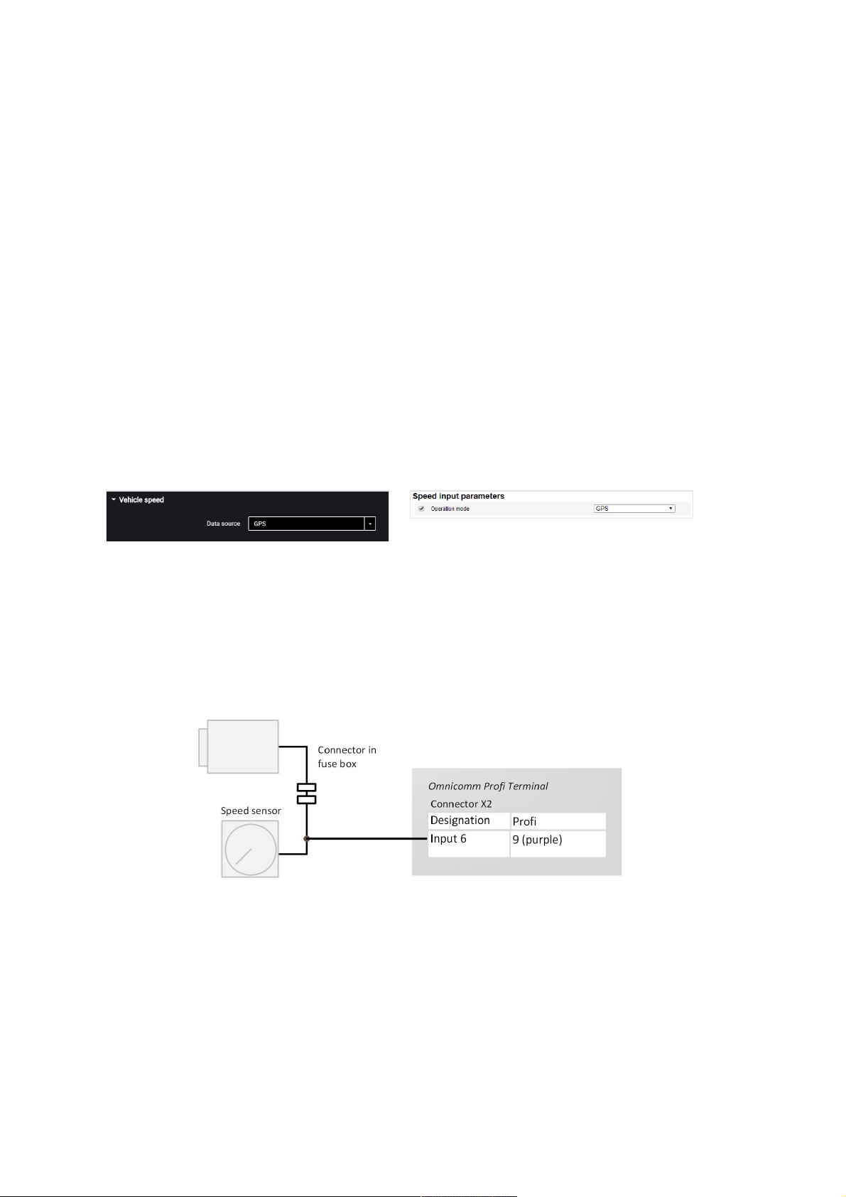
In the “Vehicle speed” section:
“Data source” – select the data to process the speed values. Possible options: “GPS”,
“CAN bus” or “UI6” (for Omnicomm Profi, Profi Wi-Fi).
Connection to universal input No.6 of the Terminal Omnicomm Profi, Profi Wi-Fi is
performed depending on the type of speed sensor.
Connection to pulse speed sensor is made according to the diagram:
Engine RPM
In the “Settings” tab select the “Inputs” section from the list.
In the “The engine revolutions” section:
Operation Parameters Setting
31
Page 32
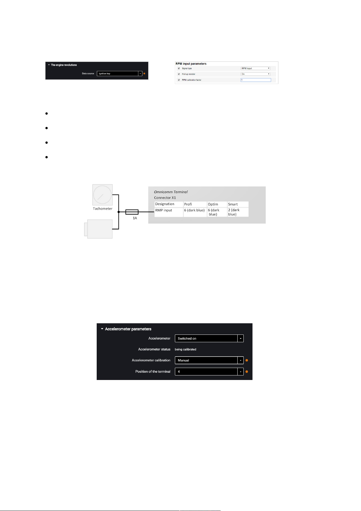
“Data source” – select the signal type. Possible values:
«Disabled»
«Ignition key»
«CAN bus»
«RPM input»
Connect the tachometer to the Terminals according to the diagram:
The place of connection to the tachometer shall be the point in the vehicle electric
network, in which the pulse signal frequency is proportional to the engine RPM.
Driving Safety Control
In the “Settings” tab select the “Additional equipment” section from the list.
In the “Accelerometer parameters” section:
“Accelerometer” – enable/disable the use of accelerometer for measuring the vehicle
acceleration.
“Accelerometer status” – accelerometer condition. Possible options: not used,
calibration, calibrated, calibration error.
“Accelerometer calibration” – select the accelerometer calibration mode.
Operation Parameters Setting
32
Page 33
Prior to performing the calibration, firmly fix the terminal and do not change its
position during operation.
Automatic calibration is recommended for vehicles that are operated mainly at speeds
above 50 km/h. Automatic calibration takes from 2 minutes to 24 hours depending on
the frequency of accelerations and braking on straight sections of the road.
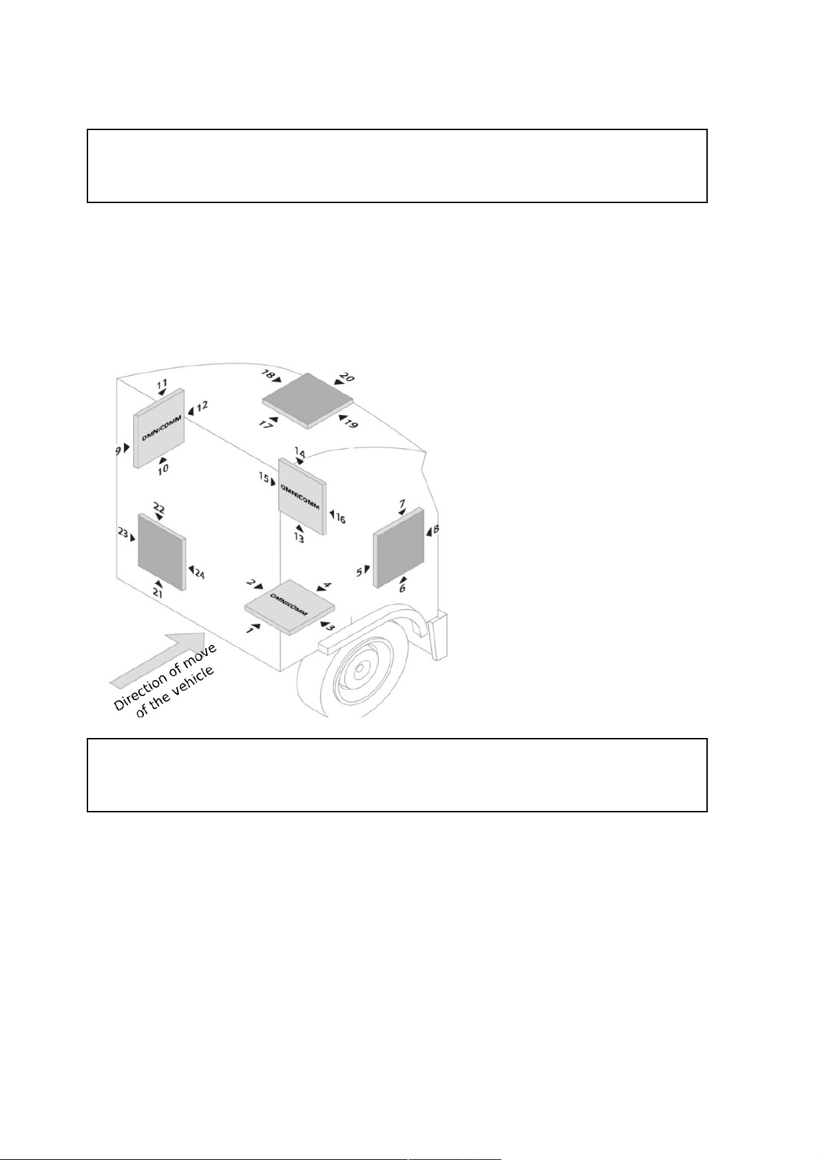
When selecting manual calibration, in the “Position of the terminal” field, select one of
24 positions as shown in figure:
Arrow ► indicates the location of
the terminal connector.
The “Omnicomm” inscription in
the figure corresponds to the
top cover of the terminal.
Deflection of the terminal from the axes during manual calibration should not be
more than 5 degrees.
In the “Settings” tab select the “Driving Control” section from the list.
“Control of dangerous driving” – enable/disable registration of dangerous driving
when exceeding the set values of monitored parameters.
Operation Parameters Setting
33
Page 34
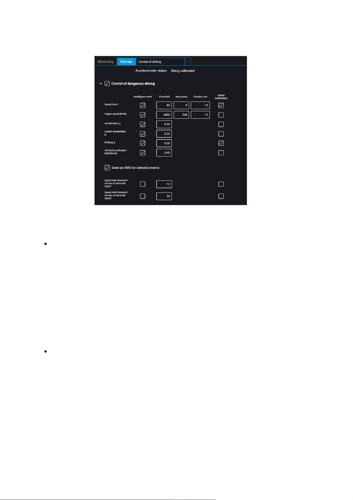
Select monitored parameters:
“Event reporting” – enable/disable event sending to Omnicomm Online.
“Speed” – vehicle speed control
Threshold – enter the maximum permissible speed, upon exceeding which dangerous
driving will be registered. Possible values: from 0 to 150 km/h. Default value: 80 km/h.
Deviation – enter the speed value that can be exceeded by maximum permissible
speed without triggering dangerous driving registration. Possible values: from 0 to 50
km/h. Default value: 5 km/h.
Duration – enter the period of time allowed to exceed maximum permissible speed
without triggering dangerous driving registration. Possible values: from 0 to 300 s.
Default value: 15 s.
“RPM” – engine RPM monitoring
Threshold – enter the maximum permissible engine RPM, upon exceeding which
dangerous driving will be registered. Possible values: from 0 to 10,000 rpm. Default
value: 4,000 rpm.
Deviation – enter the RPM value that can be exceeded by maximum permissible RPM
without registration of violation. Possible values: from 0 to 1000 rpm. Default value:
200 rpm.
Duration – enter the period of time allowed to exceed maximum permissible engine
RPM without registration of dangerous driving. Possible values: from 0 to 300 s.
Operation Parameters Setting
34
Page 35

Default value: 15 s.
“Acceleration” – acceleration control during vehicle speeding up
Threshold – enter the value of acceleration while speeding up, which exceeding will
trigger registration of dangerous driving
“Lateral acceleration” – acceleration control during vehicle turning
Threshold – enter the value of acceleration while turning, which exceeding will trigger
registration of dangerous driving
“Braking” – acceleration control during vehicle braking
Threshold – enter the value of acceleration while braking, which exceeding will trigger
registration of dangerous driving
“Vertical acceleration (pounding / bumping)” – acceleration control during vehicle
pounding
Threshold – enter the value of acceleration while pounding or bumping, which
exceeding will trigger registration of dangerous driving
“Speed and threshold exceeding of potential UI1”
Threshold – enter the value of speed, which exceeding will trigger registration of
dangerous driving, if universal input No.1 is closed/open.
“Speed and threshold exceeding of potential UI2”
Threshold – enter the value of speed, which exceeding will trigger registration of
dangerous driving, if universal input No.2 is closed/open.
The notification for the event "Speed and Exceeding of threshold of potential UI1,
UI2" is generated only when the selected speed source is "GPS" (see Selection of
Speed Source).
“Send SMS for selected events” – enable SMS sending upon registration of
dangerous driving
“Send photo for selected events” – enable digital camera photo sending upon
registration of dangerous driving
“Sound notification” – enable/disable sound notification if thresholds of monitored
parameters are exceeded. To run sound notification connect a sound emitter to
Operation Parameters Setting
35
Page 36
controlled output No.1.
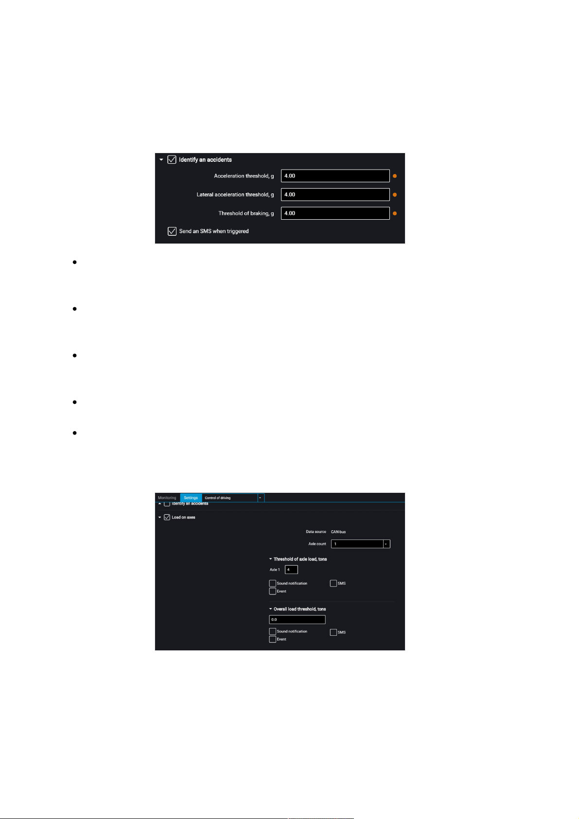
“Determine accidents” – enable/disable accident registration upon exceeding the set
values of monitored parameters.
“Speeding up threshold” – value of acceleration while speeding up, which
exceeding will trigger registration of accident
“Lateral acceleration threshold” – value of acceleration while turning, which
exceeding will trigger registration of accident
“Braking threshold” – value of acceleration while braking, which exceeding will
trigger registration of accident
“Send SMS upon triggering” – enable SMS sending upon registration of accident
“Send photo upon triggering” – enable digital camera photo sending upon
registration of accident
“Load on axes” – enable/disable control of vehicle axle load and total vehicle load.
“Data source” displays the axle load data source. Possible options: ALM Weight
Indicator and CAN.
To select the ALM Weight Indicator as a data source choose Indicator in the RS-485 or
RS-232 interface configuration.
Operation Parameters Setting
36
Page 37

To select the CAN bus as a data source enable SPN 582 and SPN 928 in the CAN
settings tab.
If the ALM Weight Indicator and the CAN Bus are both set as data source, the ALM
Weight Indicator will be used.
“Number of axles” – set the number of vehicle axles. Possible values: from 1 to 8.
Maximum value – 8 for CAN, 6 for ALM.
“Axle load threshold, tonnes” – enter the value of load on each axle, upon exceeding
which an event will be registered.
“Sound notification” – enable/disable sound notification if thresholds of monitored
parameters are exceeded
“Events” – enable/disable event sending to Omnicomm Online
“Photo” – enable digital camera photo sending upon load exceeding
“SMS” – enable SMS sending upon load exceeding
“Total load threshold, tonnes” – enter the value of total vehicle load, upon exceeding
which an event will be registered.
“Sound notification” – enable/disable sound notification if thresholds of monitored
parameters are exceeded
“Events” – enable/disable event sending to Omnicomm Online
“Photo” – enable digital camera photo sending upon load exceeding
“SMS” – enable SMS sending upon load exceeding
Body Tampering Control
In the “Settings” tab select the “Additional equipment” section from the list.
In the “Case tampering detection” section:
“Send an SMS upon an attempt open the case” – enable/disable SMS sending upon
triggering the anti-tamper switch.
Internal Battery
Operation Parameters Setting
37
Page 38
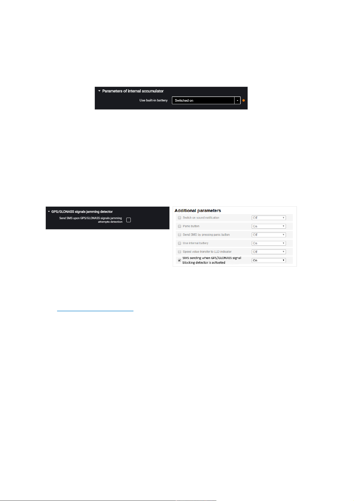
In the “Settings” tab select the “Additional equipment” section from the list.
In the “Parameters of internal accumulator” section:
“Use built-in battery” – enable/disable use of internal battery when the main power
supply is turned off and the terminal is operating in the “Collect data at jolting” mode.
GPS / GLONASS Signal Jamming Detector
For Omnicomm Optim, Profi, Profi Wi-Fi terminals in the “Settings” tab select the
“Additional equipment” section from the list.
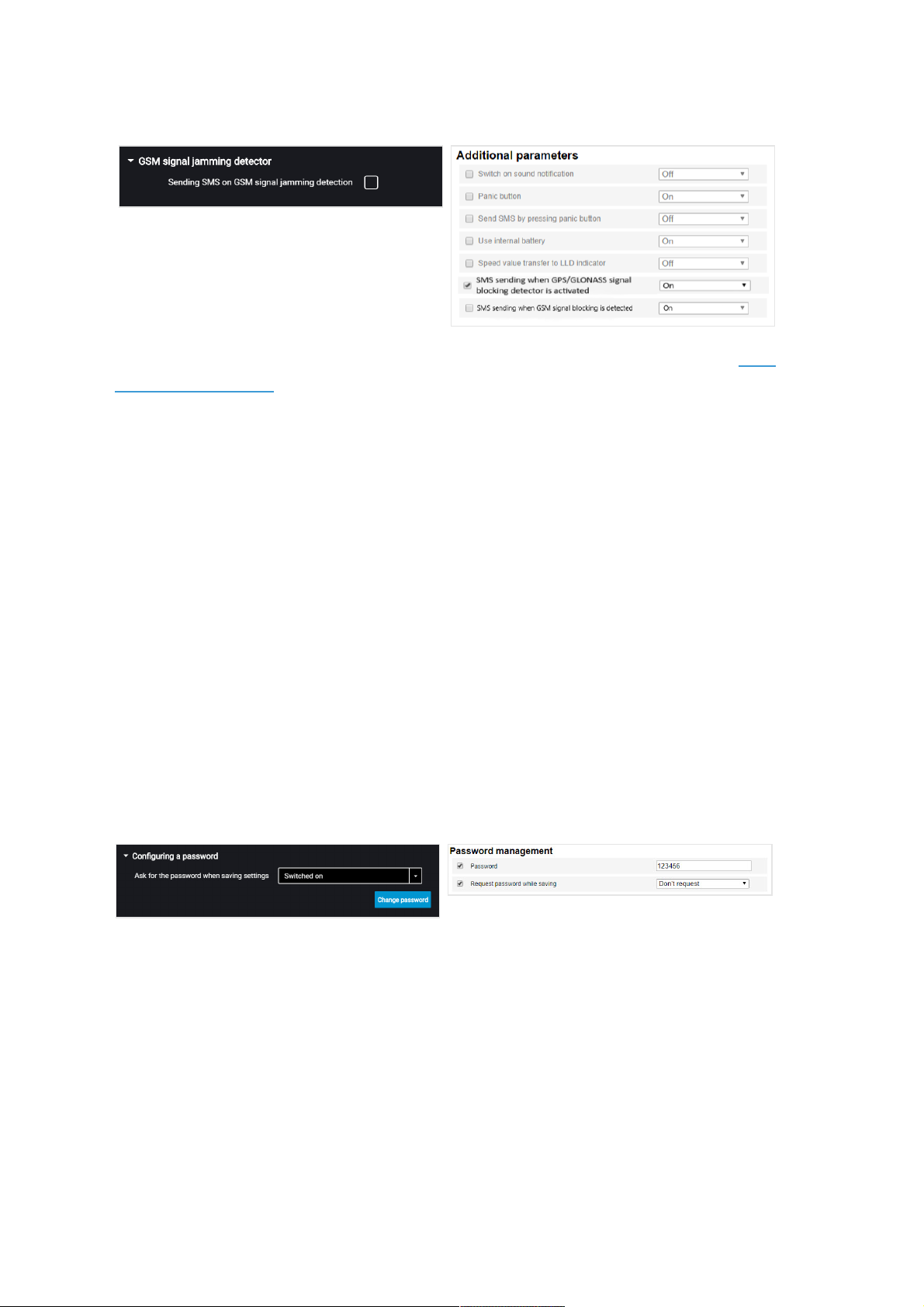
In the “GPS / GLONASS Signal Jamming Detector” section:
“SMS sending upon GPS / GLONASS signal jamming detection” – check the box to
send SMS upon registering the jamming of GPS / GLONASS.
GPS/GLONASS jamming detector can be activated when SMS configuration is enabled
(see GSM and SMS parameters).
GSM Signal Jamming Detector
For Omnicomm Profi and Profi Wi-Fi terminals in the “Settings” tab select the
“Auxiliary equipment” section from the list.
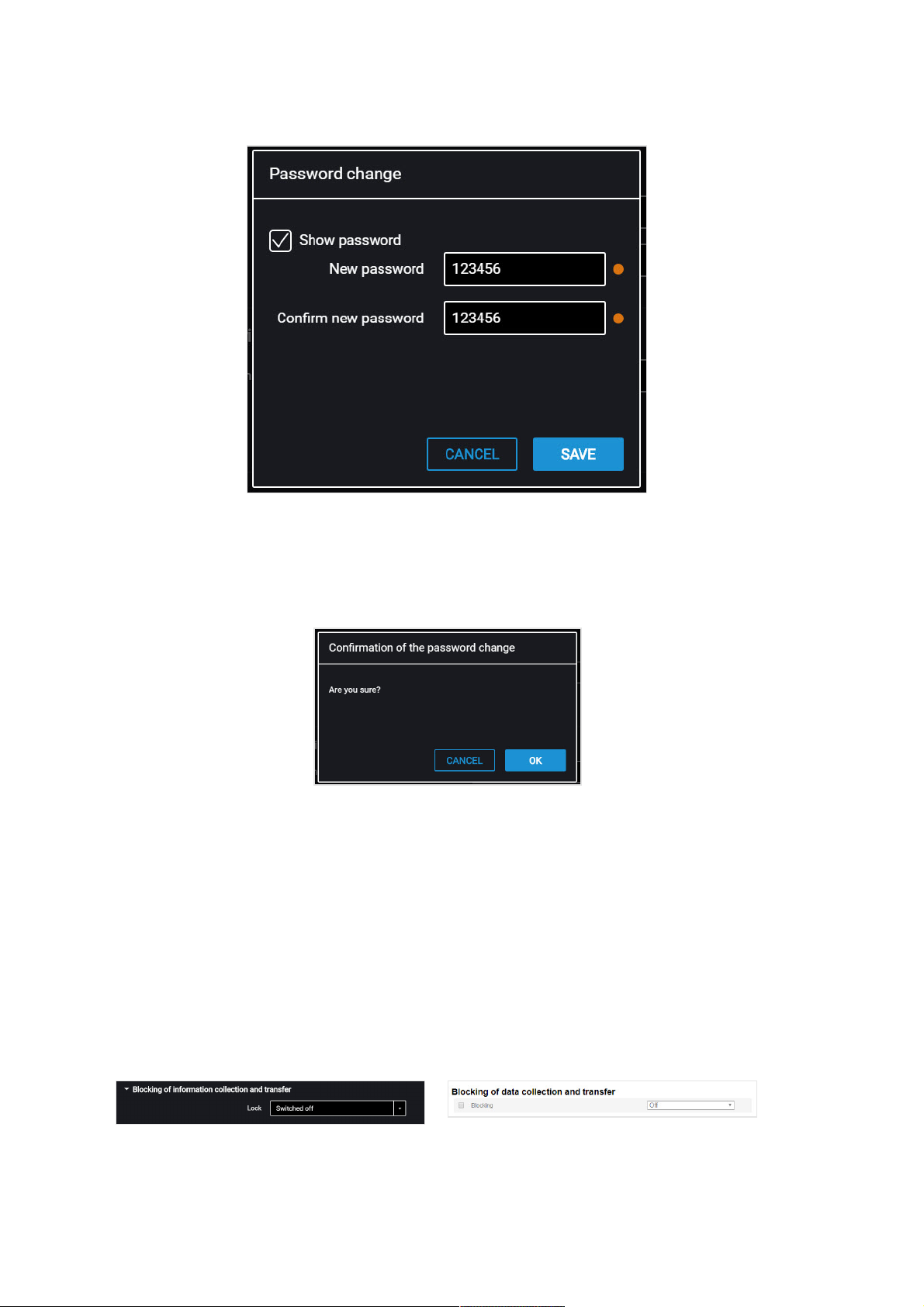
In the “GSM Signals Jamming Detector” section:
Operation Parameters Setting
38
Page 39
GSM jamming detector can be activated when SMS configuration is enabled (see GSM
and SMS parameters).
“Send SMS upon GSM signals jamming attempts detection” – check the box to send
SMS upon registering the GSM network signal jamming.
Service Functions
Terminal Reboot
In the “Service” menu select “Restart Terminal”.
Setting Password on Configuration Changing
In the “Settings” tab select the “Additional equipment” section from the list.
In the “Configuring a password” section:
If you need to use a password to configure the terminal settings, in the field “Ask for
password when saving settings” select “Enabled”. Press the “Change password”
button. A window will open:
Service Functions
39
Page 40
“New password” and “Confirm new password” – enter a new password that will be
used to get access to settings configuration. The password shall contain 8 characters
maximum.
Press the “Save” button. A window will open:
Press the “Ok” button.
Press the “Write to device” button.
Data Collection and Transmission Blocking
In the “Settings” tab select the “Connection” section from the list.
In the “Blocking of information collection and transfer” section:
To block the terminal data acquisition and transmission in the “Lock” field select
“Switced off”:
To unlock data acquisition and transmission use Omnicomm Configurator or send
Service Functions
40
Page 41

SMS command *UNBLOCK# to the SIM card, inserted in the terminal.
Remote Configuration Server Operation Setting
Set password on terminal settings modification by either of the following ways:
When configuring the terminal using Omnicomm Configurator set password on
settings modification that is different from the password set by default. Password
set by default – empty line
Send SMS command to change password set by default: *SETPWDID 235009988
12345#
where: 235009988 – terminal ID; 12345 – password to be set. The password shall
contain 8 characters maximum and may include any digits and letters.
The previously set password cannot be changed in this way.
After 6 hours, the terminal will be authorized on the Remote Configuration Server and
will be available for operation via the Remote Configuration Server.
Terminal SIM Card Number Identification
The terminal SIM card telephone number is automatically displayed in the Remote
Configuration Server after the second connection to the RCS.
SMS sending shall be enabled for the SIM card.
Additional Equipment
RS-485 and RS-232 Interfaces
Connection of auxiliary equipment (CAN-Log, PP-01 passenger throughput sensors,
DV-1 driver display, JPEG camera, data reception from vehicle J1708 data bus,
reception and transmission of navigation data as per NMEA standard) is carried out
through RS-485 and RS-232 interfaces. When needed, it is recommended to use the RS232 to RS-485 converter.
In the “Settings” window open the “Inputs” tab:
Additional Equipment
41
Page 42
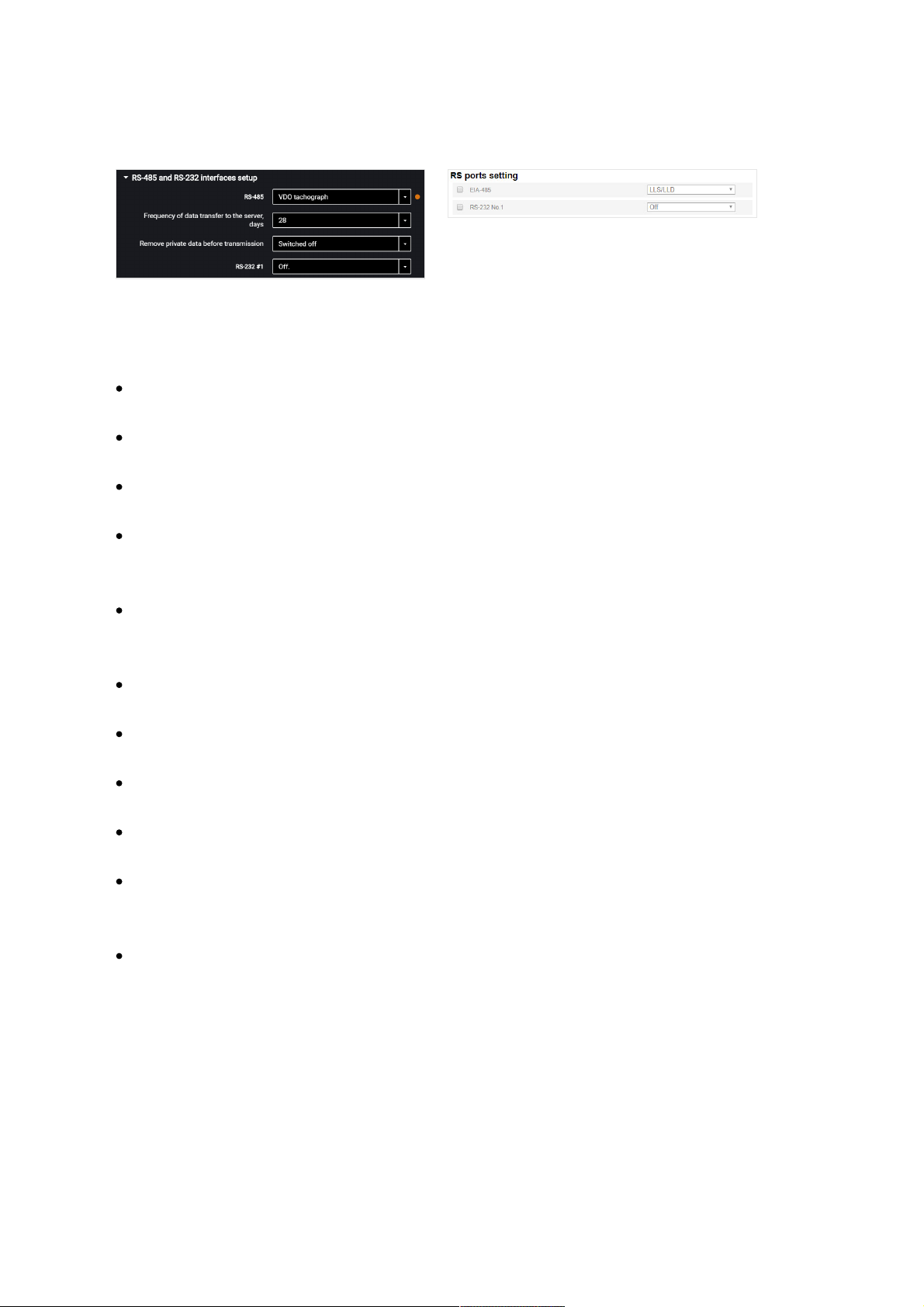
For Omnicomm Smart terminal you may only configure interface RS-485.
For RS-485 and RS-232 interfaces choose the setting:
“Disabled” – interface is not used
“CAN-Log” – connection to a CAN-log device
“J1708” – connection to the vehicle J1708 data bus
“NMEA reception” – use of navigation data from an external device. If you select
this option, you must specify the data port bit rate.
“RS port bit rate for NMEA data” – select the data port bit rate for reception of
navigation data from an external device
“NMEA transmission” – use of the terminal navigation data in an external device
“PP-01” – use for connection of the passenger throughput sensor
“Camera” – use for the digital camera connection
“DV-01” – use for the driver display connection
“LLS / LLD” – use for connecting fuel level sensors Omnicomm LLS, Omnicomm LLD
indicator
“Tachograph VDO” (only in Omnicomm Configurator) – use for Continental
tachograph connection
“Frequency of data transmission to server” – select the number of days for the DDD
files transmission to the communication server. Possible options: from 1 to 28 days.
“Delete personal data before transmission” - if necessary, enable deleting the driver's
personal data prior to data submission to the server.
Additional Equipment
42
Page 43

“iQFreeze” (except for Omnicomm Smart) – use for connection of the refrigerator
control device
“ALM Weight Indicator” – use for connection to the axle load monitoring device
“Modbus (Struna +, PMP-201)” – use for connection to the level gauge PMP-201 or
the Struna + system
“TPMS Pressure Pro” (ony for RS-232 interface) – use for connection of the tire
pressure sensors though TPMS Pressure Pro protocol
“Truck-TPMS” (ony for RS-232 interface) – use for connection of the tire pressure
sensors though Truck-TPMS protocol
“TPMS 6-13” (ony for RS-232 interface) – use for connection of the tire pressure
sensors though TPMS 6-13 protocol. The terminal transmits temperature data with
an interval of 20 degrees: -40,-20, 0, +20,…, +100. The frequency and transmission
depend on the energy-saving settings of the wireless pressure sensors configured
in accordance with the TPMS user manual.
Additional Equipment
43
Page 44

Fuel Level Sensors
In the “Settings” tab select the “Inputs” section from the list.
In the “Fuel Level Sensors” section:
“Data source” – select the type of fuel level sensors. Possible options:
“Digital LLS” – when connecting fuel level sensors Omnicomm LLS
“Frequency LLS-AF” – when connecting fuel level sensor Omnicomm LLS-AF
“Vehicle sensor” – when connecting the vehicle standard fuel sensor
“CAN Bus” – when connecting to the CAN bus
“Struna +” (except for Smart) – when connecting to the “Struna +” system
“PMP-201” (except for Smart) – when connecting the level gauge PMP-201
“Disabled” – in case fuel level control is not required.
When Omnicomm LLS and Omnicomm LLS-AF fuel level sensors are connected:
“Number of connected sensors” – specify the number of sensors connected to the
terminal.
When choosing LLS fuel level sensors connected to a universal input, you need to
configure the universal input. For automatic configuration of the universal input in
Omnicomm Configurator press the “Configure UI” button.
“Filtration” – enter the size of inner filter. Possible options of filtration:
“None” – filtration is performed only according to the settings in the
Omnicomm LLS sensor
“Weak” – used in case of product installation in stationary fuel storages and nonmobile machinery
“Medium” – used in case of vehicle's operation in normal road conditions
“Strong” – used in case of vehicle's operation in normal and severe road conditions
“Maximum” – used in case of vehicle's operation in severe road conditions and
when connecting a standard fuel sensor with analog output
Additional Equipment
44
Page 45
When connecting to the “Struna +” system or the “PMP-201” sensor:
“Fuel tank volume, L” – enter the fuel tank volume. Possible values: 0 to 65,000
“Current fuel volume, L” – displays the current volume according to the “Struna +”
system or the “PMP-201” sensor
Connect the “PMP-201” sensor and the “Struna +” system according to the
documentation on these devices. You may connect only one “Struna +” system. The
network address, by default, is 80.
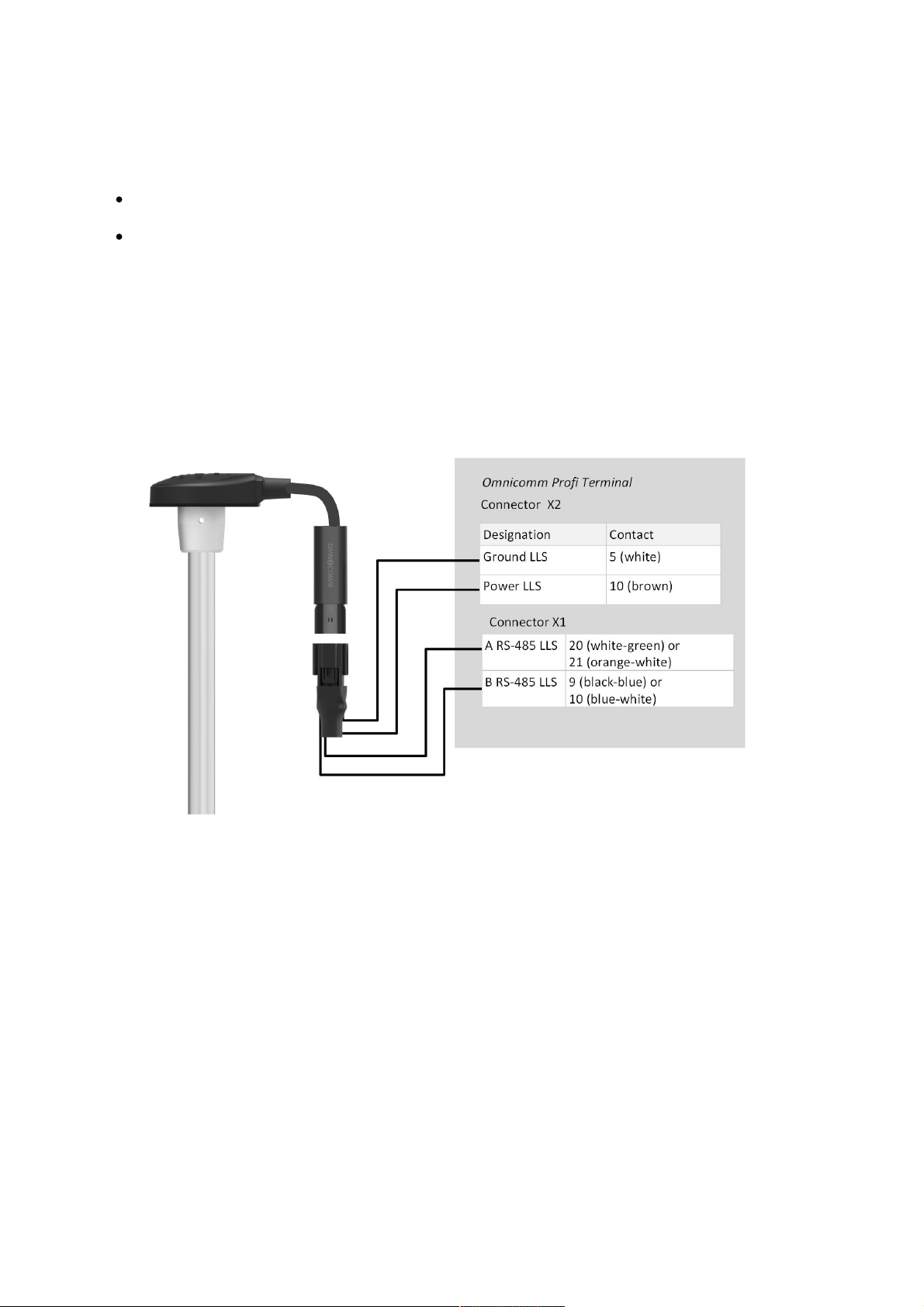
Connect one Omnicomm LLS fuel level sensor to the Terminal Omnicomm Profi, Profi
Wi-Fi according to the diagram:
Connect Omnicomm LLS-AF fuel level sensor to the Terminal Omnicomm Profi, Profi
Wi-Fi according to the diagram:
Additional Equipment
45
Page 46
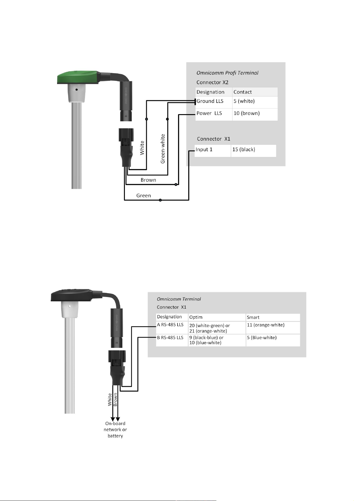
Connect several Omnicomm LLS-AF sensors to the terminal one by one, starting with
1 universal input.
Omnicomm LLS-AF sensor must be set to output a frequency signal in the range from
30 to 1053 Hz.
Connect one Omnicomm LLS fuel level sensor to the terminal Omnicomm Optim and
Smart according to the diagram:
Additional Equipment
46
Page 47
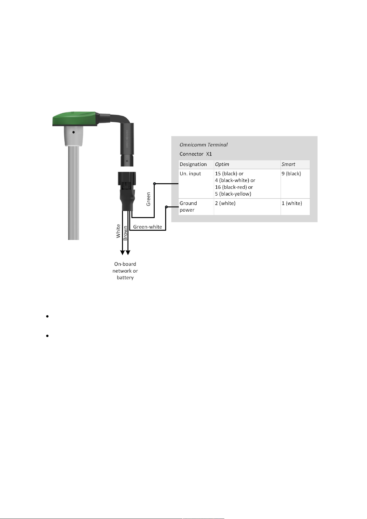
Connect one or more Omnicomm LLS fuel level sensors side-by-side via the RS-485
interface.
Connect Omnicomm LLS-AF fuel level sensor to the terminals Omnicomm Optim and
Smart according to the diagram:
When connecting the terminals to the “Struna +” system or the “PMP-201” sensor:
“Fuel tank volume, L” – enter the fuel tank volume. Possible values: 0 to 65,000
“Current fuel volume, L” – displays the current volume according to the “Struna +”
system or the “PMP-201” sensor
Connect the “PMP-201” sensor and the “Struna +” system according to the
documentation on these devices. You may connect only one “Struna +” system. The
network address, by default, is 80.
Omnicomm ICON Display
In the “Settings” tab select the “ICON” section from the list.
Additional Equipment
47
Page 48

“ICON” – check the box to display data from the terminal on the Omnicomm ICON
Display
“Network address” – select the display network address. Possible values: from 7 to
254
“Select time zone” – check the box to select the time zone with reference to UTC.
The value of the time zone is used in case where automatic accounting of time
zones is not required
“Time zone” – select the time zone
“Receive messages from dispatcher via SMS” – check the box to display SMS
received at the SIM card number of the terminal. Format of the message sent:
D2ddispatcher text. Maximum message length: 128 characters.
“Notify about reading the message via SMS” – check the box to send the SMS
reading confirmation. Notifications are sent to the dispatcher’s number specified
when configuring the terminal (view Connection to Communication Servers)
“Notify about changing the status via SMS” – check the box to send SMS to the
dispatcher’s number about changing the driver's status. Notification contains the
new status of the driver.
“Sound notification” – check the box to enable sound notification when registering
the event specified when configuring the terminal and the display
In the “Settings” tab select the “Additional equipment” section from the list.
“Engine hours by RPM”, fill in the RPM to engine hours conversion table:
Additional Equipment
48
Page 49
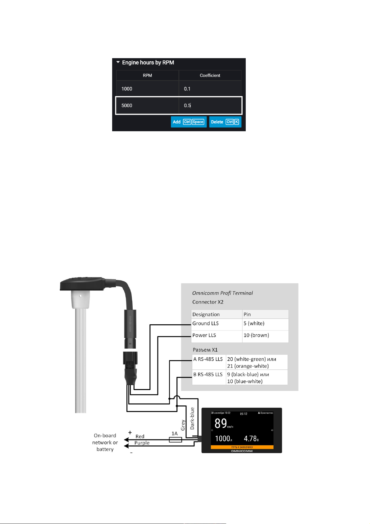
Enter the RPM value in the “Revolutions per minute” field, in “Coefficient” field enter
the value of conversion factor to calculate engine hours.
The conversion factors are determined based on the vehicle operating conditions.
Maximum number of rows – 5.
The engine hours are displayed in hours with a decimal part (1.50 equals to 1 hour
and 30 minutes) in the format HH.XX within the range of up to 100 engine hours and
HHH.X for 100.0 - 999.9 engine hours. If the number of engine hours is higher than
1000, the last three significant digits and one symbol after the decimal point are
displayed.
All engine hours are recorded in the terminal and sent to the CS as accrued total.
Connect Omnicomm Profi terminal to Omnicomm ICON display according to the
diagram:
Additional Equipment
49
Page 50
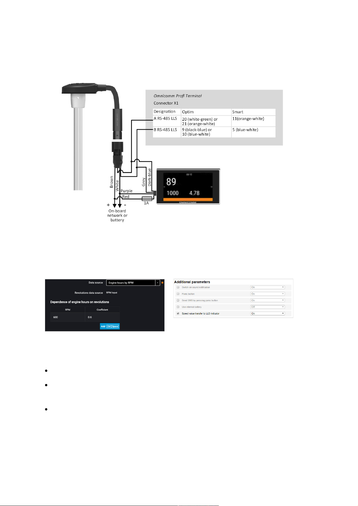
Connect Omnicomm Profi, Smart terminal to Omnicomm ICON display according to
the diagram:
Omnicomm LLD Indicator
In the “Settings” tab select the “Additional equipment” section from the list.
In the “Data transmission to Omnicomm LLD indicator” section
“Data source” – select the data source to display the value on the Omnicomm LLD
indicator. Possible options:
“GPS speed” – displays the vehicle speed
“Universal input“ – displays the status or values on the terminal universal input
depending on the connected auxiliary equipment
“Engine hours by RPM” (only for Profi, Profi Wi-Fi, Optim) – displays vehicle engine
hours
When selecting “Motor hours by RPM”, fill in the table of RPM recalculation to motor
hours as follows:
Additional Equipment
50
Page 51
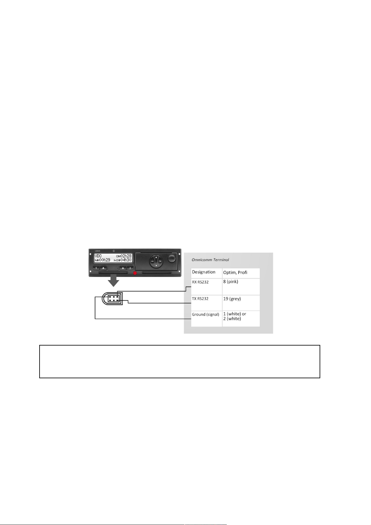
In the field “Revolutions per minute” enter the value of RPM, in the field “Factor” enter
the value of conversion factor to calculate the motor hours value.
The conversion factors are determined based on the operating conditions of the
vehicle.
Maximum number of rows – 5.
Engine hours are displayed on the LLD indicator as hour values with a fractional part
(1.50 means 1 hour 30 minutes) in the format HH.XX in the range of up to 100 hours
and HHH.X in the range of 100.0 to 999.9 engine hours. If the number of engine hours
is more than 1000, the last three significant figures are displayed and one symbol
after the decimal point.
Motor hours are fully recorded in the terminal and sent to the CS on a continuous
accrual basis.
Tachograph
Connect the Continental tachograph to the Optim terminal via RS-232 and RS-485
according to the diagram:
Power connections of the terminal and the tachograph must be made similarly: either
both before, or both after the vehicle battery disconnect switch.
If needed, it is recommended to use the RS-232 to RS-485 converter.
To read the DDD files from the Continental tachograph, in the program configure the
RS-232 or RS-485 interface of the terminal.
Universal Inputs
Universal inputs are intended for connecting the auxiliary equipment with pulse,
direct-current, analog or frequency output and its operation monitoring.
Additional Equipment
51
Page 52
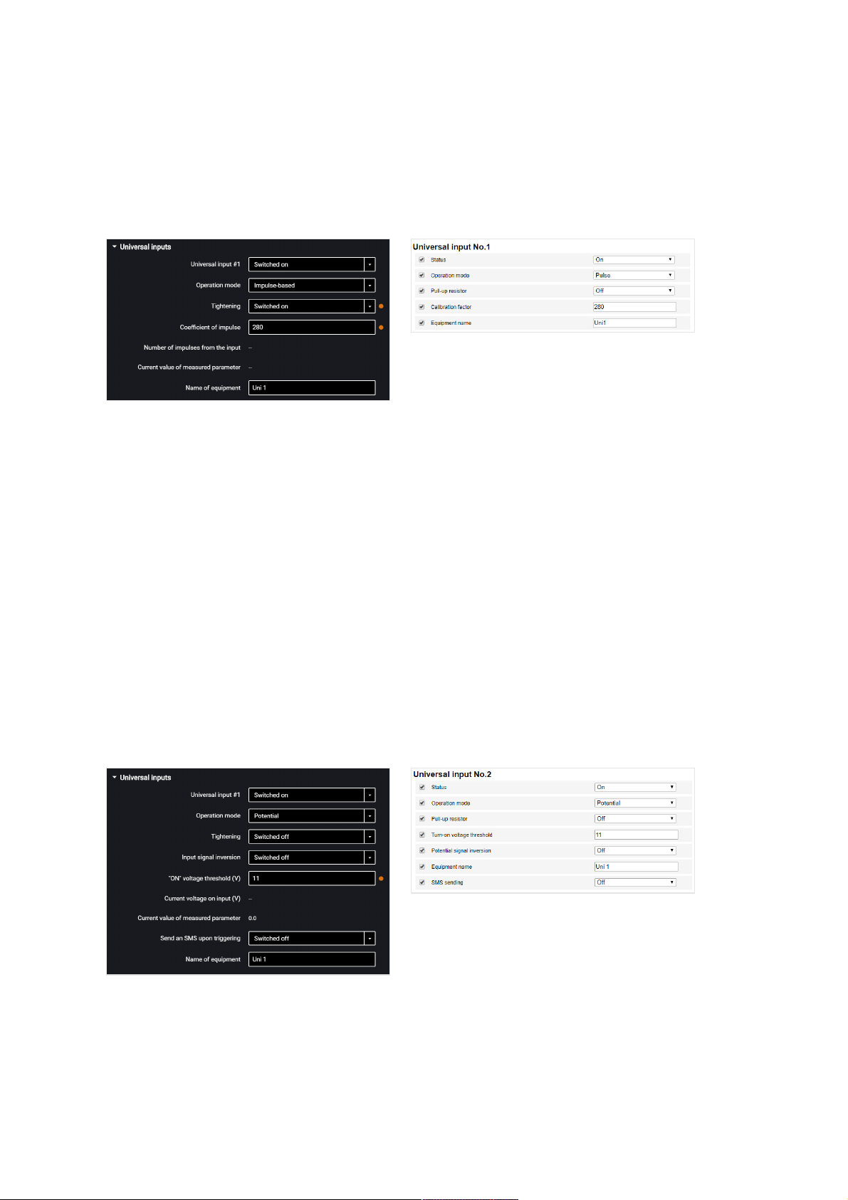
In the “Settings” tab select the “Inputs” section from the list.
In the “Universal Inputs” section:
Sensors with pulse output
“Universal input” – select “Enabled”.
“Operating mode” – select “Pulse”.
“Equipment name” – enter the monitored parameter name.
“Pull-up resistor” – select “Enabled” when working with “open collector”-type sensors
or contact sensors.
“Coefficient of impulse” – enter the calibration factor converting the number of pulses
to the determined physical quantity.
“Number of pulses from the input” (in Omnicomm Configurator) – number of pulses
coming at the universal input.
“Current value of measured parameter” – displays the value at the input with account
for the calibration factor.
Sensors with potential output
“Universal input” – select “Enabled”.
“Operating mode” – select “Potential”.
“Potential input activation voltage threshold” – set the value of voltage threshold,
Additional Equipment
52
Page 53
after which the terminal will record activation of the sensor. Default value – 9 V.
“Pull-up resistor” – select “Enabled” when working with “open collector”-type sensors
or contact sensors.
“Input signal inversion” – set “Enabled” for the sensor with open contacts or contacts
closing on commission of any action.
“Current voltage” – value of the voltage at the universal input of the terminal.
“Current value” – auxiliary equipment switched on or off.
“SMS sending upon triggering” – select “Enabled” to send SMS when the directcurrent universal input is triggered.
“Equipment name” – enter the monitored parameter name.
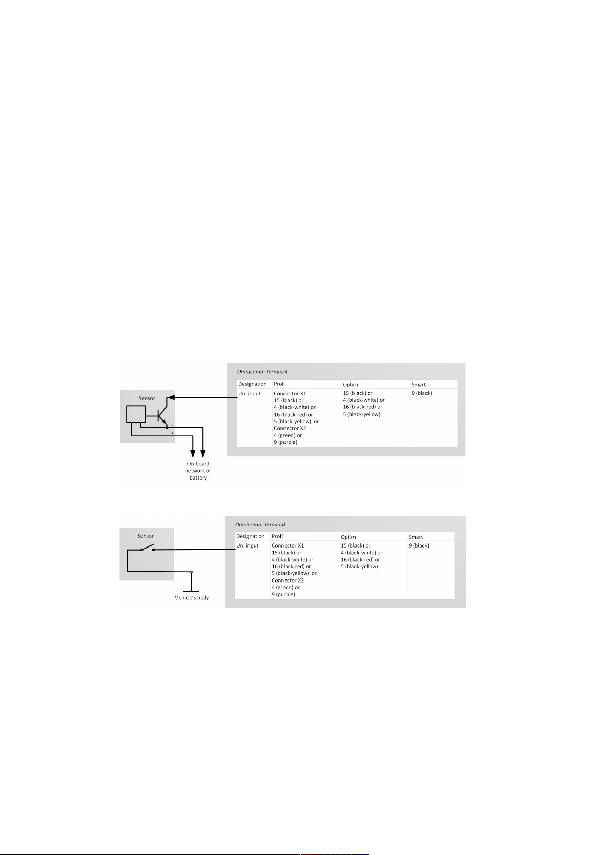
Possible sensor types: contact or contactless digital sensors.
Connect contactless sensors (capacitance, inductance, optical magnetic) and N-P-N
sensors with “open collector”-type input according to the diagram:
Connect the contactless sensor according to the scheme:
As the contact sensor you can use standard elements of equipment control (activation
buttons / limit switches / sensors triggered by excess pressure or temperature, etc.) or
an additionally mounted sensor. We recommend that you first look for possibility of
connection to a standard device and install an additional sensor only if there is none.
Additional Equipment
53
Page 54
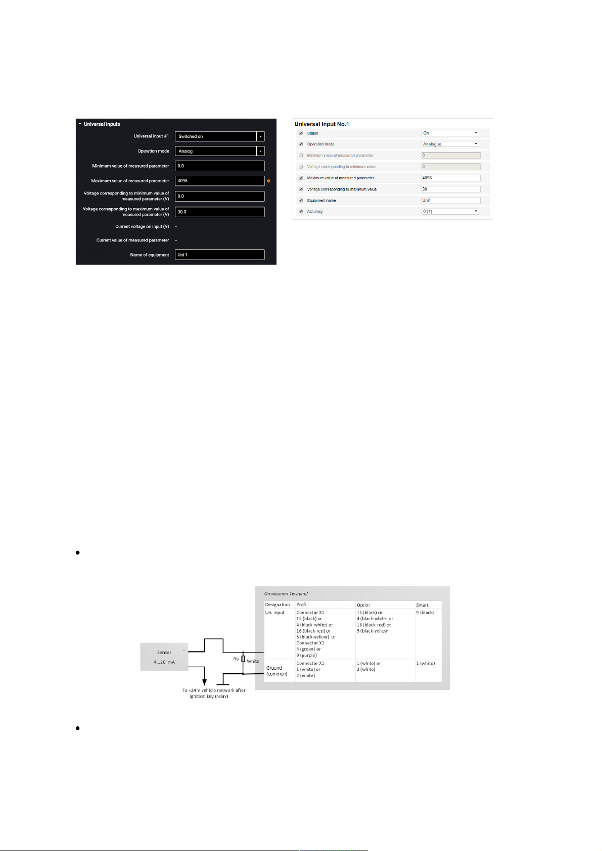
Sensors with analog output
“Minimum measured value” – set the minimum value to be measured by the sensor
(in the units of measurement of this value).
“Voltage corresponding to the minimum value” – set the value of voltage
corresponding to the minimum measured value.
“Minimum measured value” – set the minimum value to be measured by the sensor
(in the units of measurement of this value).
“Voltage corresponding to the maximum value” – set the value of voltage
corresponding to the maximum measured value.
“Current voltage at universal input” – value of the voltage at the universal input of
the Terminal.
“Current value of measured parameter” – current measured value.
“Equipment name” – enter the monitored parameter name.
Analog sensor types:
with uniform current output:
with uniform voltage output:
Additional Equipment
54
Page 55
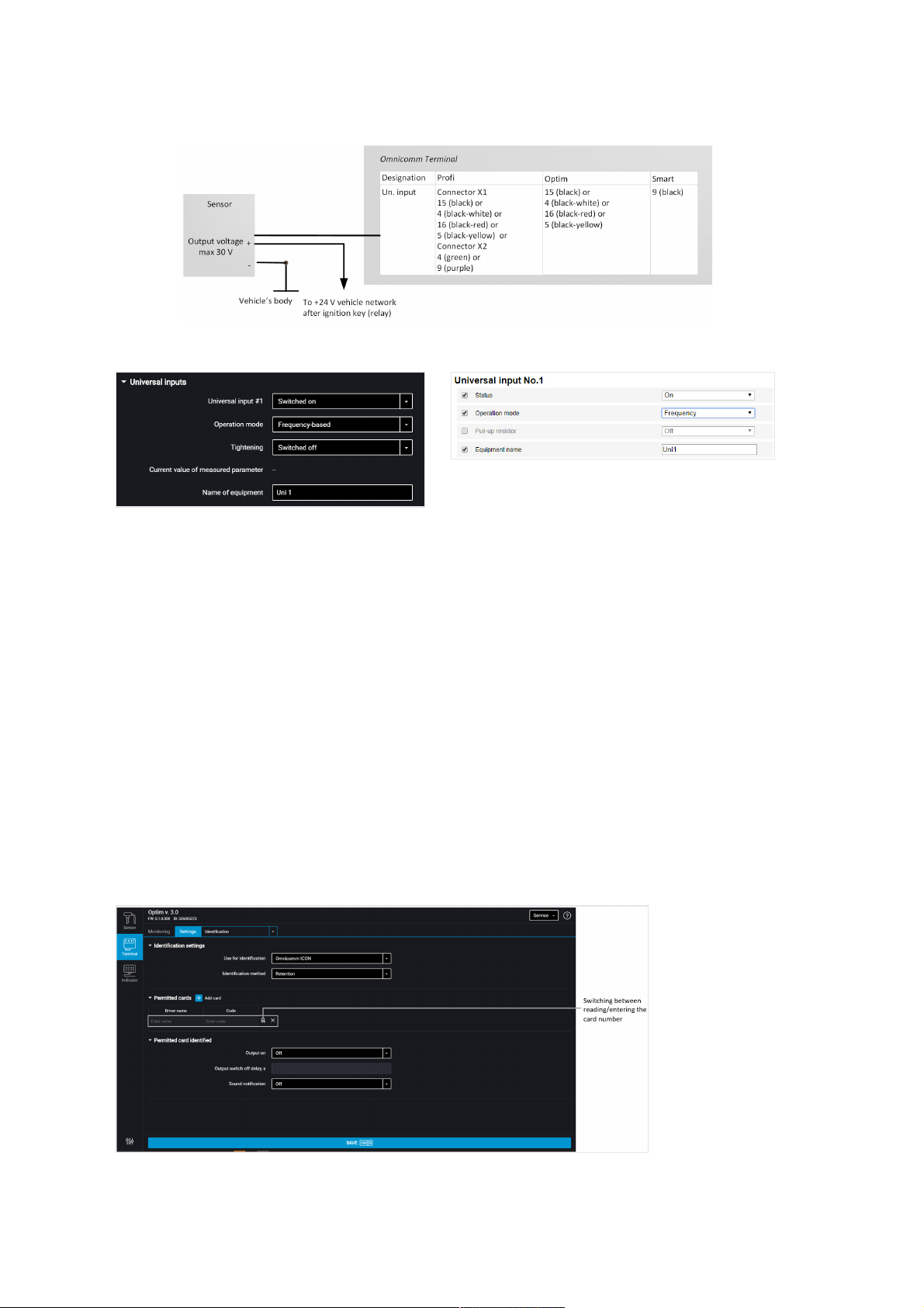
Sensors with frequency output
“Universal input” – select “Enabled”.
“Operating mode” – select “Frequency”.
“Pull-up resistor” – select “Enabled” when working with “open collector”-type sensors
or contact sensors.
“Current value at universal input” – current measured value.
“Equipment name” – enter the monitored parameter name.
Driver Identification
In the “Settings” tab select the “Identification” section from the list.
For Omnicomm Optim, Profi, and Profi Wi-Fi terminals, in “Identification settings”
section:
Additional Equipment
55
Page 56

“Use for identification” – select the identification method. Possible options:
“1-wire” – when performing identification with iButton key
“Omnicomm ICON” – when performing identification with Omnicomm ICON display
“Identification method” – select the method of identification. Possible options:
“Applying” – the identification is performed when a card or a key is applied for the
period of time specified in the parameter “Key/card identification time”.
“Retention” – identification is performed by holding the card on the reader. This
method is applied for identification via Omnicomm ICON display using the
cardholder.
“Key/card identification duration” – specify the time value when iButton/card key is
applied, after which will be enabled the second digital output of the terminal. Possible
values: from 0 to 60 seconds. For automatic reading of the card number, connect
Omnicomm ICON display to the terminal, switch on the readout mode and apply card.
In the “Authorized keys” section press the “Add key / card” button and enter the
iButton / card key numbers, which application will enable the second digital output.
The key number is indicated in 6-byte format.
For example, for a key you must enter: 000015AF6D2B
If no key/card is indicated in this section, the events will be recorded for all applied
keys/cards.
“Output activation” – select “enabled” if you want to activate the second discrete
output when the iButton / card authorized key is applied.
“Output cut off delay” – specify the time after disconnecting the iButton / card key
from the readout device, after which the second digital output will be disabled.
Possible values: from 0 to 3600 seconds.
If necessary, enable/disable the sound reminder of the driver’s authorization in the
Additional Equipment
56
Page 57
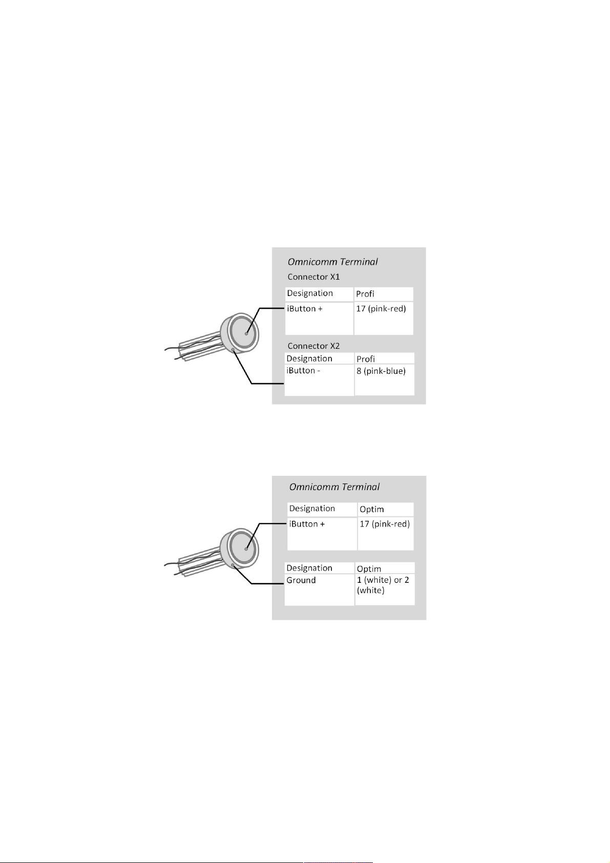
field “Enable sound reminder” – “Yes”/”No”, respectively.
iButton readout device connection and installation
Determine the correspondence of the wire colours to the readout device contacts,
ringing out the wires and readout device body contacts with each other using
multimeter.
Connect iButton readout device to the Omnicomm Profi, Profi Wi-Fi Terminal
according to the diagram:
Connect iButton readout device to the Omnicomm Optim Terminal according to the
diagram:
iButton readout device must be installed on the vehicle front panel or in the service
cover on the vehicle front panel.
At the installation site, drill a hole Ø9 mm, install the iButton readout device, put on
the ring and lock washer.
Connect the sound emitter:
1. Connect the yellow-red wire of the sound emitter to the controlled output of the
terminal, connect the brown wire to +12 V /(+24 V) vehicle network
Additional Equipment
57
Page 58
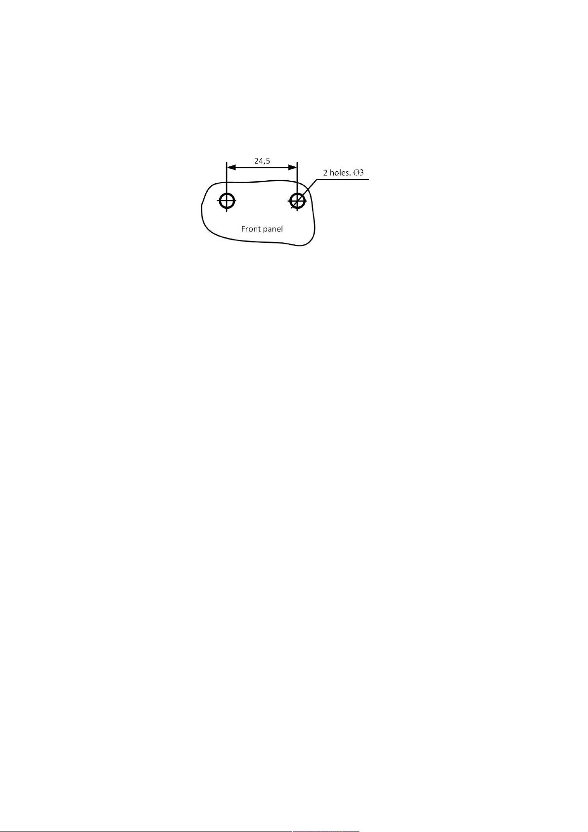
2. Perform installation on/under an inclined or horizontal surface of the vehicle cabin
front panel, fixing it with screws (self-tapping screws) or glue
3. At the installation site, when using screws, drill holes as shown in figure:
4. Mount the sound emitter on the prepared surface and fix.
Additional Equipment
58
Page 59
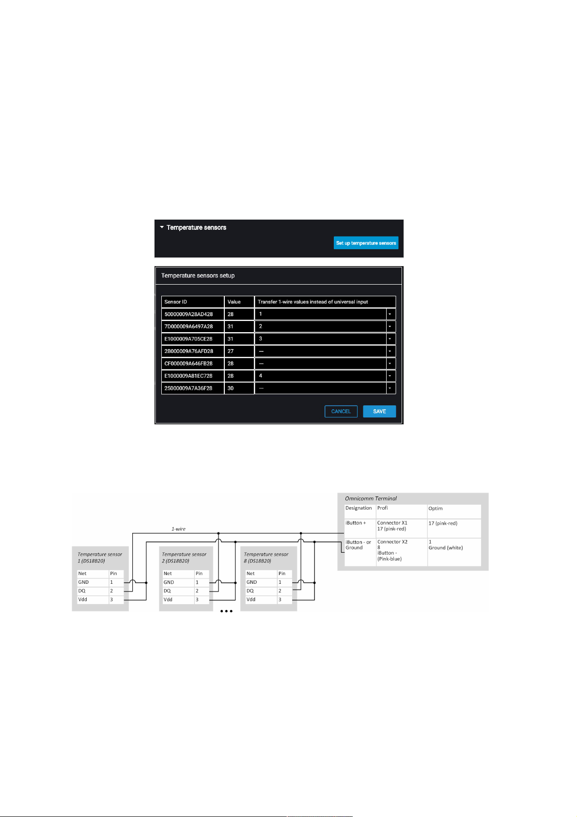
Temperature Sensor
Omnicomm Optim terminals support connection of up to 8 temperature sensors.
In the “Settings” tab select the “Auxiliary equipment” section from the list.
The “Temperature sensors” section displays the readings of temperature sensors
connected to 1-Wire interface:
“Send value of 1-Wire sensor instead of UI” – select the number of the universal input
for displaying the temperature values in Omnicomm Online.
Connect the temperature sensors according to the diagram:
Voice Communication
Connect the voice communication set for Omnicomm Profi, Profi Wi-Fi terminal
according to the diagram:
Additional Equipment
59
Page 60
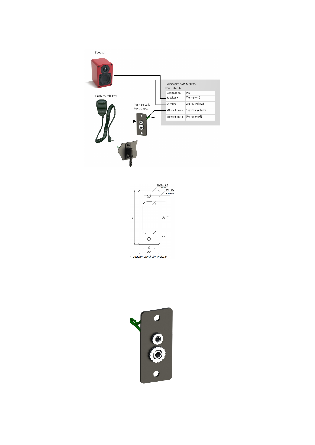
1. At the installation site, drill two holes Ø2.5 mm:
2. Drill a rectangular hole 30×12 using a milling cutter or drilling bit and install a push-
to-talk key adapter
3. Fix the push-to-talk key adapter on the surface with self-tapping screws
4. Connect the push-to-talk key connector with the adapter connector:
5. Mini Jack 2.5 mm connector pin array to connect active speaker and Auxiliary
Additional Equipment
60
Page 61
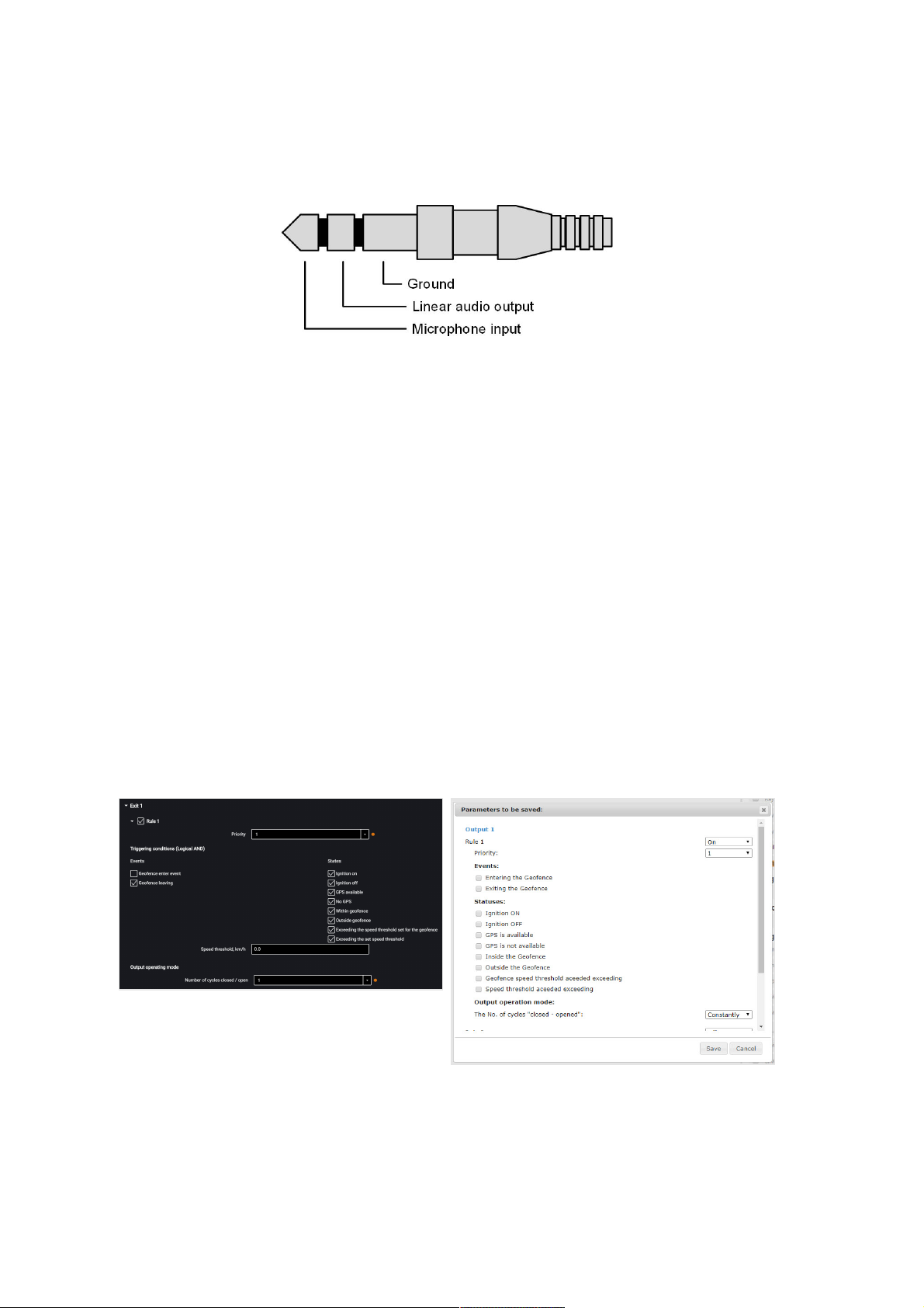
Equipment Omnicomm 3.0 Terminals 65 microphone to the Omnicomm Optim
terminal is shown on the diagram:
RFID Reader Connection
The terminal supports connection of swipe card readout devices via 1-Wire physical
interface.
The connected readout device must fully simulate the exchange protocol of DS1990A
product.
Timing diagrams must be executed for all officially declared specifications.
Controlled Equipment
In the terminals, for each controlled output, up to three rules are provided for
operation.
The rules are set by event or by a combination of events and states.
In the “Settings” tab select the “Outputs” section from the list.
“Rule priority” – set the priority of the rule. When at the same time several rules apply,
a rule with the highest priority is used.
Possible options: 1 (highest), 2, 3 (lowest).
Additional Equipment
61
Page 62

Select “Events”:
Entering the geofence
Leaving the geofence
Select “States”:
Ignition on
Ignition off
GPS available
No GPS
Being in geofence
Being outside geofences
Exceeding speed threshold set for geofence
Exceeding the set speed threshold
In the “Output operation mode” section:
Number of “closed-open” cycles – specify the number of output enabling/disabling.
Possible options:
continuous – the output is always enabled (only available for states)
from 1 to 9 – (only relevant for events, because for states fulfillment of this
condition would lead to indefinite cycles repeating)
When selecting the number of cycles, specify:
“Delay before closing” – specify the time period until the output will be activated.
Possible values: from 0.1 to 9.9 s.
“Duration of closing” – specify the time, during which the output must be activated.
Possible values: from 0.1 to 9.9 s.
“Duration of opening” – specify the time until the next output activation. Possible
values: from 0.0 to 29.9 s.
Example 1.
The following values are set:
State – “Being in geofence”
Additional Equipment
62
Page 63
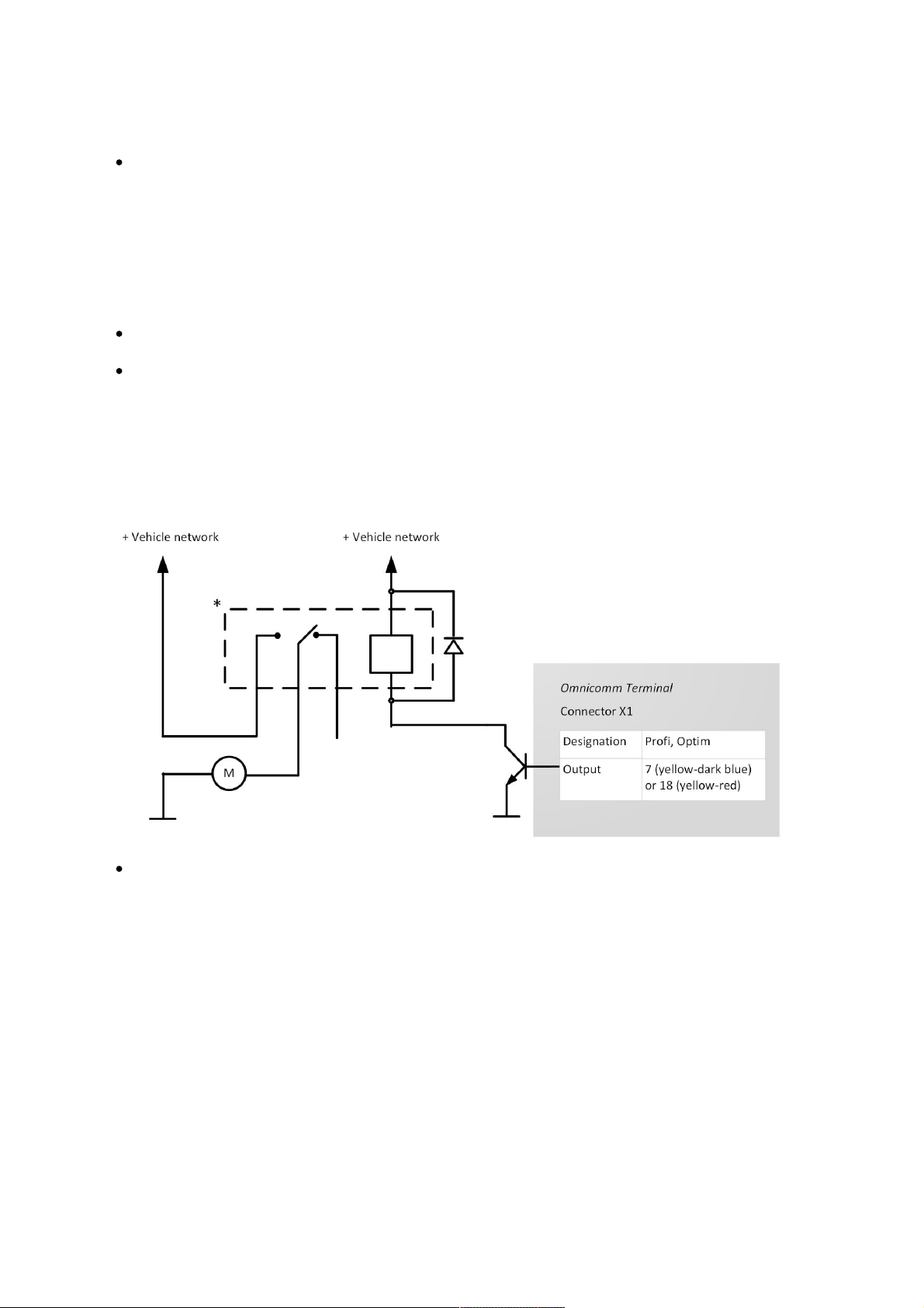
Number of “closed-open” cycles – 5
If the vehicle is inside the geofence, the output will be enabled and disabled 5 times.
Output enabling/disabling (5 times each) will be repeated until the vehicle exits the
geofence.
Example 2. The following values are set:
State – “Being outside geofence”, “GPS available”
Number of “closed-open” cycles – “Continuous”
If the vehicle is outside the geofence and the GPS module data are valid, the output
will be enabled, until the moment of entering the geofence or GPS data absence.
Connect auxiliary equipment to controlled outputs of Omnicomm Optim terminals
according to the diagram:
Relay with operation voltage suitable for the voltage of this vehicle network (12 or
24 VDC)
You can also control digital output by SMS commands: *SETDOUT param#,
*GETDOUT#, *CLRDOUT param#
Geofences Setting
In the terminals, geofence setting is provided to enable the controlled outputs.
In the “Settings” tab select the “Geofences” section from the list.
Additional Equipment
63
Page 64
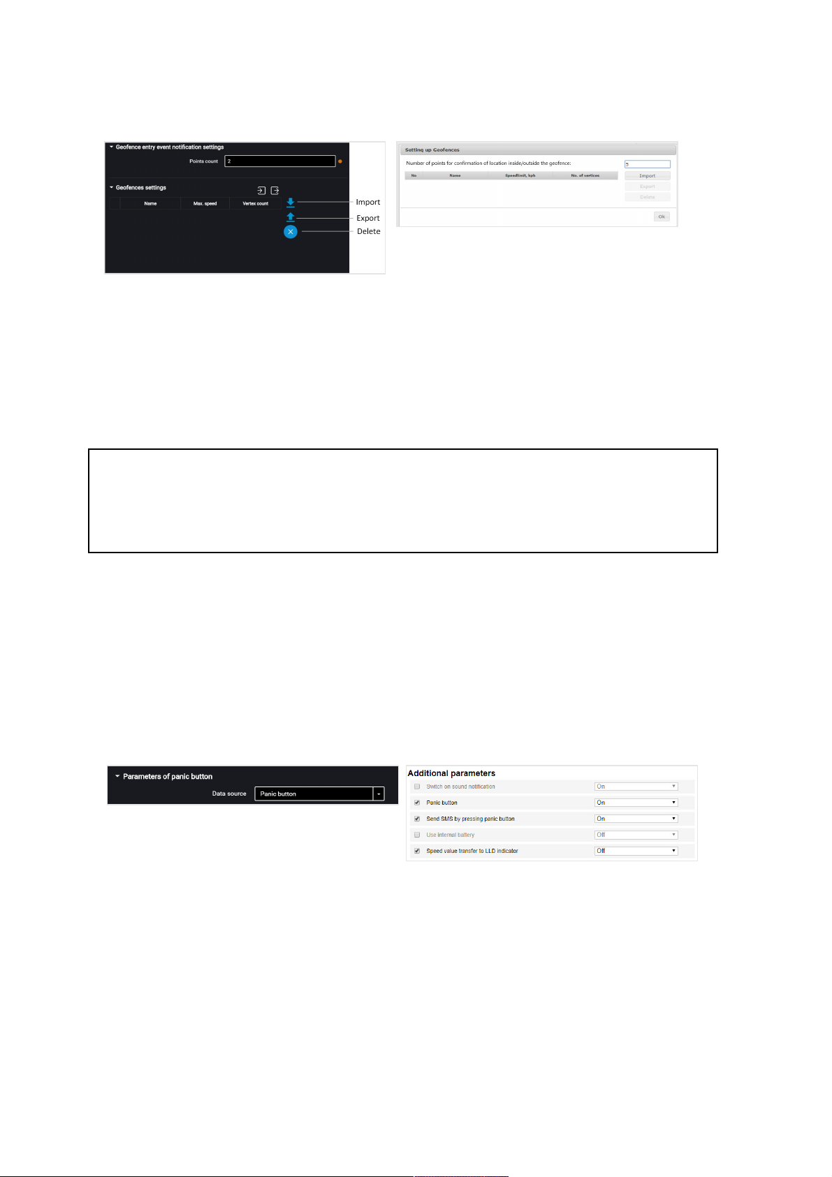
“Number of points to confirm being inside/outside the geofence” – specify the
number of successively defined vehicle coordinates required to register the vehicle
being inside or outside the geofence. Coordinates determination period – 1 sec.
Possible values: from 1 to 10.
To add a geofence, press the “Import” button and select the .xml file with geofence
settings.
The geofence name must be not more than 8-character long and consist of symbols,
digits and Latin letters.
Geofence should not contain consecutive points with the same coordinates.
Maximum number of geofences – 6.
Maximum number of peaks – 24.
Panic Button and GSM Call Button
In the “Settings” tab select the “Additional equipment” section from the list:
In the “Parameters of punic button” section:
“Data source” – enable/disable condition control of the panic button.
“SMS sending upon triggering” – enable/disable SMS sending upon the panic button
pressing.
Connect the panic button according to the diagram:
Additional Equipment
64
Page 65
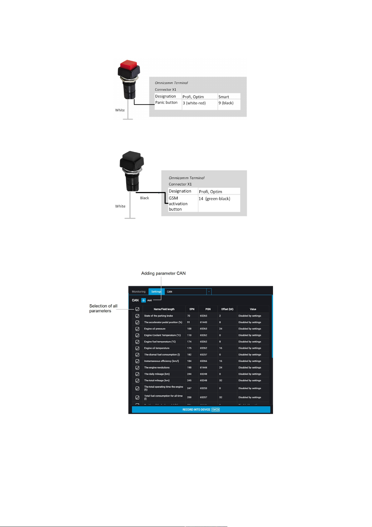
Connect the GSM activation response button to Omnicomm Optim, Profi and Profi WiFi terminals according to the diagram:
CAN Bus
In the “Settings” tab select the “CAN” section from the list:
Additional Equipment
65
Page 66
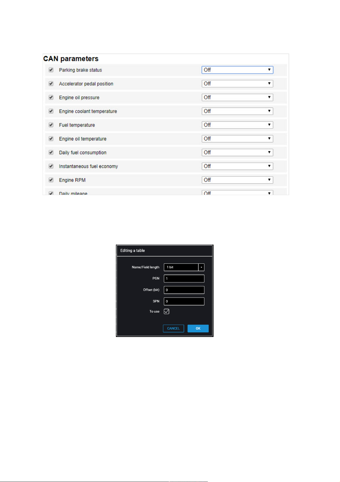
From the list, select the parameters, which value shall be displayed in
Omnicomm Online, and check the corresponding boxes in the column “Use”.
If you need to add parameters for reading from the CAN bus, which are not on the list,
in Omnicomm Configurator press button “Add”. A window will open:
“Length” – select the length of data packet. Possible values: 1, 2, 3, 4 (bit), 1, 2, 4 (bytes).
“PGN” – enter the parameter group number that defines the contents of the
corresponding message according to SAE J1939. Possible values: from 1 to 262143.
“Offset” – enter the offset value relative to the base address of the bit storing area.
Possible values: 0 to 63.
“SPN” – enter the parameter code according to SAE J1939. Possible values from 0 to
4294967295.
“Use” – check the box if you want to read this parameter from the CAN bus.
Additional Equipment
66
Page 67
Press the “Save” button.
Perform connection to the vehicle CAN bus using wireless CAN reader device (CANcrocodile).
When using wireless CAN reader devices, connect the terminals according to the
diagram:
Configuring the reception of data on the fuel volume in the tank from the vehicle
CAN bus Connect and configure reception of the vehicle equipment operation
parameters from CAN J1939 data bus and set the setting of fuel sensor – “CAN Sensor”.
Check indication of the fuel sensor values in the “Monitoring” tab, the value must be
from 0 to 4095.
When reading the fuel level in the tank from the CAN bus, set the operating mode of
the terminal while ignition off to “Acquire data during pounding” mode. Otherwise,
the fuel level graphic will not be displayed correctly.
Additional Equipment
67
Page 68

Specifications
Omnicomm Profi,
Profi Wi-Fi
Omnicomm Optim Omnicomm Smart
Communication
Satellite Navigation Systems GLONASS/GPS GLONASS/GPS GLONASS/GPS
GPRS data transmission channel GPRS
Wi-Fi (only for
Profi Wi-Fi)
GPRS GPRS
Number of SIM cards and SIM
chips
1 SIM-card + 1
SIM-chip
2 SIM-card or 1 SIM-
card + 1 SIM-chip
1 SIM-card
Capability of installing SIM Yes Yes No
Power source
Power supply voltage, V 8…65 8…65 8…30
Overvoltage protection Yes Yes No
External sensor power supply Yes No No
Backup battery capacity, mAh 1400 1400 -
Data acquisition and transmission
Data acquisition period, s 15…240 15…240 15…240
Specifications
68
Page 69
Non-volatile memory capacity,
events
150 000 150 000 150 000
SD card for photographs and
archieve
No Yes No
Inputs and outputs
Ignition key input Yes Yes Yes
Panic button input Yes Yes Connection to
universal input
RPM sensor input Yes Yes Yes
GSM call button input Yes Yes No
Number of universal inputs 6 4 1
Number of digital outputs 2 2 -
Interfaces
CAN interface Yes Yes Yes
Interface RS-485 2 2 1
Interface RS-232 1 1 -
Omnicomm Profi,
Profi Wi-Fi
Omnicomm Optim Omnicomm Smart
Communication
Specifications
69
Page 70
USB interface Yes Yes Yes
Voice communication
connection
Yes Yes No
Interface 1-wire Yes Yes No
Built-in accelerometer Yes Yes Yes
Design
Dimensions, mm 100,5 x 137,0 x
38,0
101,0 х 90,0 х 31,5 101,0 х 90,0 х 31,5
Working temperature range, C
(without the internal battery)
– 40…+85 – 40…+85 – 40…+85
Operating temperature, C (with
the internal battery)
Charge 0…45;
Discharge -20…
60
Charge 0…45;
Discharge -20…60
Charge 0…45;
Discharge -20…
60
Body tampering sensor Yes Yes No
Antenna design External External Built-in
Capabilities
Connection of fuel level sensors 6 6 1
Omnicomm Profi,
Profi Wi-Fi
Omnicomm Optim Omnicomm Smart
Communication
Specifications
70
Page 71

Detection of active signal
jamming GSM signal jamming
Yes Yes No
Detection of active GSM signal
jamming
Yes No No
Remote control through GPRS Yes Yes Yes
Data output via external
indicator
Yes Yes Yes
SMS notifications Yes Yes Yes
Omnicomm Profi,
Profi Wi-Fi
Omnicomm Optim Omnicomm Smart
Communication
LED and Sound Notification
Indicator Indication mode Value
Power
red/green
Out Power: absent
Alternately flashes
red-green
Off Power: Main
Ignition: Off
Operating Mode: “Collect all data except GPS“
Flashing red at
interval 4 times per
second
Power: from USB (if there is charger backup battery)
LED and Sound Notification
71
Page 72

Permanently lighted
green
Power: main
Ignition: On
or
Power: Main
Ignition: Off
Operating mode “Collect all data”
Flashing red at
interval 1 time per
two seconds
Power: Main or backup battery (if any)
Ignition: Off
Operating mode: «Sleeping»
GPS
red/green
Off Module power supply off
Alternately flashes
red/green
In case of module failure, the indicator “Accident” is
lighted
Permanently lighted
green
Valid data from satellites are recieved
Permanently lighted
red
No data reception from satellites or invalis data recieved
GSM
red/green
Off Module power supply off
Permanently lighted
red
Out of coverage or GSM network search
Permanently lighted
green
Within the GSM network coverage, exchange with
communication server through GPRS channel is not
performed
Flashing red Module activation. Module switches to working mode
Indicator Indication mode Value
LED and Sound Notification
72
Page 73

Flashing green Active GPRS session. No exchange with communication
server through GPRS channel
Flashing orange
(simultaneous
flashing red and
green indicator)
Within the GSM network coverage, available data
exchange with communication server through GPRS
channel
Alternately flashes
red-green
Module error
Accident
red/green
Off No failures
Permanently lighted
red
Failure in operation (damage) of internal elements,
satellite navigation module or GSM module
Alternately flashes
red-green
Failure of exchange with one or more Omnicomm LLS
sensors
Check Omnicomm LLS settings, communication lines,
Omnicomm LLS power supply voltage as per “User Manual
Omnicomm LLS 20160, LLS 30160,LLS4, LLS 20230”
Power
and
Accident
Simultaneously
flashing red at с
interval 1 time per
second
Terminal is locked. Contact your dealer
* Note: in case of internal fault (the “Accident” indicator is on), the failure of GSM modules and
satellite receiver can be assessed by the status of indicators.
Indicator Indication mode Value
Sound notification for Omnicomm Profi Wi-Fi terminal
LED and Sound Notification
73
Page 74

Number of sound
signals
Designation
One beep The terminal has connected to a Wi-Fi access point that was specified when
configuring the terminal
Two beeps Terminal has disconnected from Wi-Fi access pointk
Three beeps The terminal has finished data transmission over the Wi-Fi network
LED and Sound Notification
74
Page 75
SMS from the Terminal
Event Message format Example
Panic
button
triggering
Panic button. Vehicle name; VID;
http://google.com/maps?
q=Latitude, Longitude; dd/mm/yyyy;
hh:ss.
Panic button. Е777КХ_97; ID336011133;
http://google.com/maps?
q=55.7889,37.5887; 01/04/19; 09:25.
Dangerous
driving is
detected
Dangerous driving. a=хх.хх g on the
X-axis; Vehicle name; VID;
http://google.com/maps?
q=Latitude, Longitude; dd/mm/yyyy;
hh:ss.
Dangerous driving. Suspension
impact>0.20 g, Е777КХ_97; ID336011133;
http://google.com/maps?
q=55.7887,37.5887; 01/04/19; 09:29.
Dangerous driving. Sharp turn>0.20 g,
Е777КХ_97; ID336011133;
http://google.com/maps?
q=55.7887,37.5887; 01/04/19; 09:29.
Dangerous driving. Acceleration>0.20 g,
Е777КХ_97; ID336011133;
http://google.com/maps?
q=55.7886,37.5887; 01/04/19; 09:33.
Dangerous driving. Braking>0.20 g,
Suspension impact>0.20 g, Е777КХ_97;
ID336011133; http://google.com/maps?
q=55.7886,37.5889; 01/04/19; 09:40.
An
accident is
detected
Accident. a=хх.хх g on the X-axis;
Vehicle name; VID;
http://google.com/maps?
q=Latitude, Longitude; dd/mm/yyyy;
hh:ss.
Accident. a>0.40 g; Е777КХ_97;
ID336011133; http://google.com/maps?
q=55.7887,37.5891; 01/04/19; 09:45.
SMS from the Terminal
75
Page 76
Universal
input
triggering
Sensor. Equipment name. UI. Vehicle
name; VID; http://google.com/maps?
q=Latitude, Longitude; dd/mm/yyyy;
hh:ss.
Uni 1 sensor. Е777КХ_97; ID336011133;
http://google.com/maps?
q=55.7887,37.5888; 01/04/19; 09:29.
Body
tampering
(excluding
Light,
Smart)
Body tampering. Vehicle name; VID;
http://google.com/maps?
q=Latitude, Longitude; dd/mm/yyyy;
hh:ss.
Body tampering. Е777КХ_97;
ID336011133; http://google.com/maps?
q=55.7886,37.5888; 01/04/19; 09:36.
Event Message format Example
SMS Commands
SMS commands for terminal management
Command Designation
Command text in SMS Reply to a command in SMS
*SOUND 1# SOUND ON Request for turning on
the siren
*SOUND 0# SOUND OFF Request for turning off
the siren
SMS Commands
76
Page 77

*SETDOUT param#
Param=0
Param=1
Param=0,1
SETDOUT
Possible parameter values:
param = OK if the command is forwarded
to execution
param = ER if the command is not
forwarded to execution
Request for enabling
digital output
*GETIMG# GETIMG param
Possible parameter values:
param = OK if the command is forwarded
to execution
param = ER if the command is not
forwarded to execution
Request for taking
picture (if the camera is
connected)
*CLRDOUT param#
Param=0
Param=1
Param=0,1
CRLDOUT param
Possible parameter values:
param = OK if the command is forwarded
to execution
param = ER if the command is not
forwarded to execution
Request for enabling
digital output
*GETDOUT# DOUT 0=1 1=0
где: output_number=output_state
Request for state of
digital output
*CONNECT# CONNECT CS_address:port Request for establishing
connection of Terminal
with CS
*GETLINK# LINK # LINK ip4_CS_address:port
date_and_time
Request for status of
connection to CS
Command Designation
Command text in SMS Reply to a command in SMS
SMS Commands
77
Page 78

*GETINFO# INFO DID=deviceID
HW=hardware_code_version
BL=bootloader_version
FW=firmware_version
REC=number_of_records_in_archive
IMEI=GSM_modem_unique_identifier
Request for state of
terminal
*RESET# RESET param
Possible parameter values:
param = OK if the command is forwarded
to execution
param = ER if the command is not
forwarded to execution
Reset of terminal
*GETSTAT# STAT terminal_date_and_time
GPS=position as per GPS
SPD=speed
IGN=ignition_state
L1=fuel_level:sensor_state
L6=fuel_level:sensor_state
Fuel level sensor state codes LLS/LLS-AF:
• 0 - disabled;
• 1 - not ready;
• 2 - ready, , frequency 20 - max Hz;
• 3 - error, frequency 0 - 19 Hz;
Request for vehicle
state
*SETPWDID vid pwdid#
vid - identification of
Terminal;
pwdid -
password/identification.
SETPWDID
ERRID/ERRNulPWD/ERRAlrSet/PWD:pwdid
OK
Setting parameter
“Password”
Command Designation
Command text in SMS Reply to a command in SMS
SMS Commands
78
Page 79

*CONNECTSC# CONNECT SC Request for connection
of terminal with
configurator server
*SETAPN apn#
apn - APN of the
operator
SETAPN apn ERR/OK Setting APN
*SETAPN2 apn#
apn - APN of the
operator of second SIM
card
SETAPN apn ERR/OK Setting APN for second
SIM card
*GPSCOLD# GPSCOLD ERR/OK Cold start of GPS
reciever
*UNBLOCK# Unblocking the terminal
Command Designation
Command text in SMS Reply to a command in SMS
SMS Commands
79
Page 80

Firmware Change Log
Date Firmware
Version
Changes
July 26,
2018
FW 305 - upgraded GPS connection (satellite loss, track gaps solved)
- failure after page reloading rectified
- track gaps in case of CS failure eliminated
January
14,
2019
FW 307 - solved factory reset issue when cleaning the terminal data archive or in
case of on-board network voltage drop
- enhanced GPS communication (eliminated periodic coordinate
discarding at 00-00 UTC)
- solved a problem of lack of communication with Profi Wi-Fi terminals, if
there is a 0 in IP-address (for example, 192.168.0.1)
- rectified freezing of Omnicomm LLS-AF fuel level sensor values when
the terminal switches to Collect all except GPS mode
March
20,
2019
FW 308 - implemented the function of collecting arbitrary CAN-parameters from
VH operating according to FMS, and displaying CAN data in
Omnicomm Online
- terminal factory reset eliminated
- solved failures of terminal time stamps, VID, PID
- added protection from satellite loss due to QZSS (Japanese Quasi-Zenith
Satellite System)
- implemented the function of the terminal calling back to the number in
case of bad voice connection
Firmware Change Log
80
Page 81

[email protected]
www.omnicomm-world.com
 Loading...