

Omnicom RS-5100 Owner's Manual
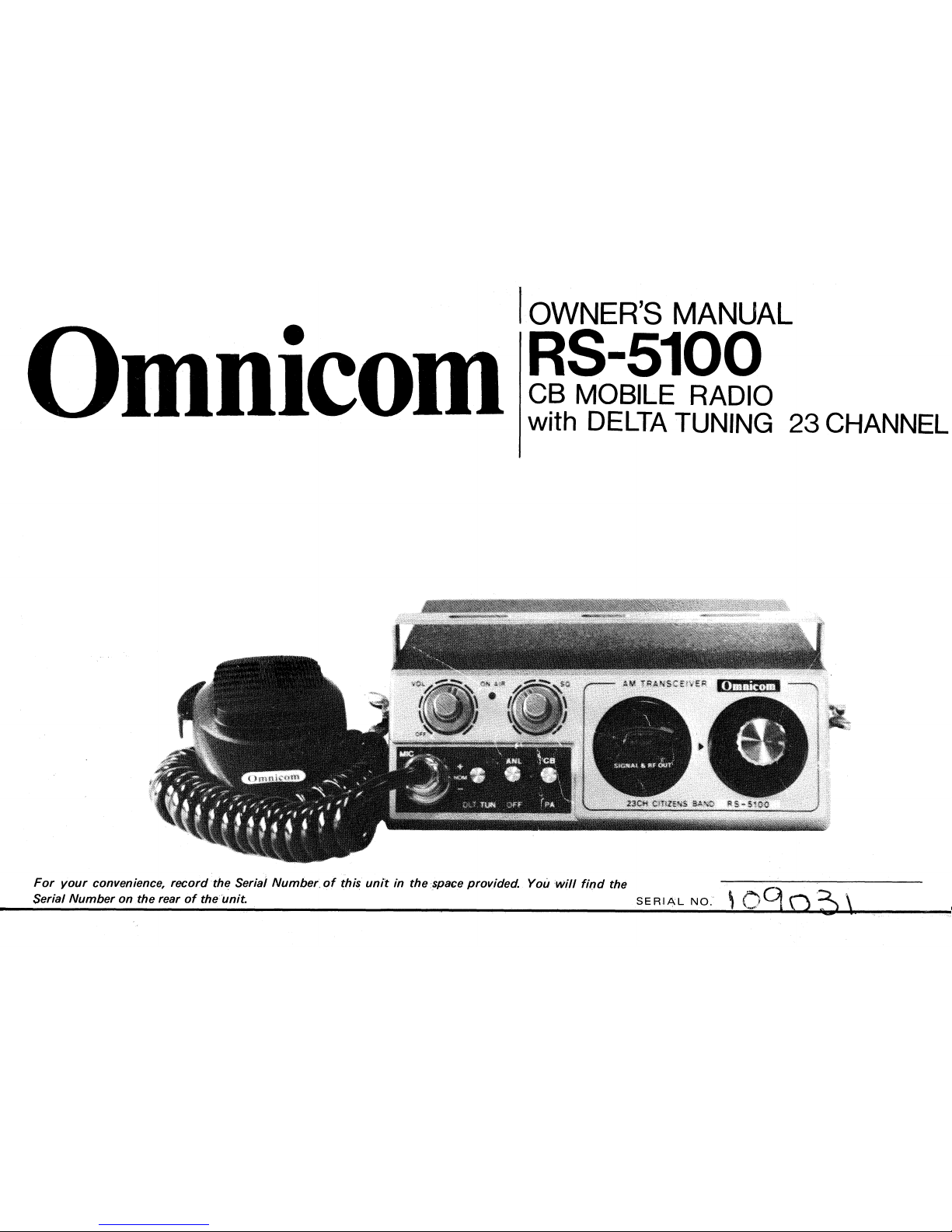
OWNER'S MANUAL
RS-5100
CB MOBILE RADIO
with DELTA TUNING 23 CHANNEL
Omnicom
For your convenience, record the Serial Number of this unit in the space provided. You will find the
Serial Number on the rear of the unit.
SERIAL NO.
IMPORTANT
Your Model RS-5100 is a 23-channel, AM Transceiver designed for licensed Class D operation on any of the 23
frequencies designated as Citizens Band channels by
,
the FCC (Federal Communication Commission).
Since this unit is designed and built to fully meet all the requirements of the FCC Rules and Regulations, it is imperative
that, before operating this unit, your read and thoroughly understand the contents of Part 95 of the FCC Rules and
Regulations prescribing the lawful operation of transceivers of this type. Part 95 regulations are available from the
Superintendent of Documents, Government Printing Office, Washington D.C. 20402.
It is also imperative for you to fill out FCC Form 505 as requested and submit it to the FCC to obtain a necessary
qualification for operation of the unit. Remember that you are strictly prohibited by law from using the unit without
having a valid station license.
Note that adjustments of the transmitter section are prohibited by the FCC with the exception that they are made by
a qualified person having a first or second class radiotelephone license, rather than a citizens band or amateur license.
DESCRIPTION
The Model RS-5100 is a fully transistorized transmitter-receiver capable of operating on any of 23 crystal-controlled
channels in 27MHz citizens radio band, and is designed to be used for either mobile or fixed station service.
It is developed through many years of our successful experiences in technology to provide sufficient transmitting power
and high receiving sensitivity; the advanced techniques employed in every part of the circuitry also assure marked
reliability and trouble-free performance.
The model comes complete with a variety of auxiliary devices such as built-in PA (public-address) amplifier, delta tune
switch, ANL (automatic noise limiter) switch, signal and RF power indicator, on-air lamp, jacks for external speaker
and PA speaker, etc., for added convenience of operation.
A microphone with press-to-talk button and a mounting bracket are also included. The model is powered by a 12V
negative or positive ground system car-battery or by an appropriate AC-DC converter for fixed station operation.
—1—

FCC DATA
PSMERITON ELECTRONIC, tr
SERIAL NO
BACK VIEW
-2-
FRONT VIEW
•
OPERATING PARTS
1.
MIC Connector
For connection of the supplied press-to-talk microphon e.
2.
Delta Tune Switch
Retunes the receiver in the input frequency when it cau ses drifting during reception.
3.
ANL Switch
Automatically reduces external electrical noise, such as pulse or ignition noise
introduced in receiving signals.
4.
CB/PA Switch
PA position is used only for public-address operation. For normal operation this
switch should be set to CB position.
5.
Squelch Control
Functions only in the receive mode. It silences the speaker while the signals are
absent and allows a quiet standby operation.
This control does not affect the receiver volume when signals are present.
6.
On-air Lamp
This lamp keeps lighting while the transmitter is in operation.
7.
OFF/Volume Control . . . . This control has two functions; power ON/OFF and receiver volume adjustments.
8.
Signal/Power Meter
A dual purpose meter which indicates relative output power during transmission and
input signal strength during reception.
9.
Channel Selector
Tunes the transmitter and receiver simultaneously in any of 23 channel frequencies.
10.
ANT Socket
For connection of antenna cable.
11.
EXT SP Jack
For connection of an external speaker.
This connection automatically shuts off the built-in speaker.
12.
PA SP Jack
For connection of a public-address speaker.
13.
Power Cable
This cable should be connected to a 12V car-battery or an AC-DC converter.
—3—
MOUNTING BRACKET
SPACER x 2
WASHER x 2
-------- TAPPING SCREW x2
TOOTHED LOCK WASHER .2
WING BOLT x 2
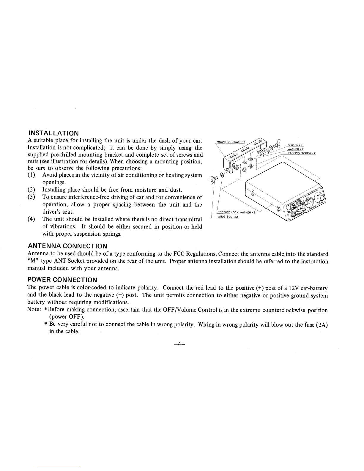
INSTALLATION
A suitable place for installing the unit is under the dash of your car.
Installation is not complicated; it can be done by simply using the
supplied pre-drilled mounting bracket and complete set of screws and
nuts (see illustration for details). When choosing a mounting position,
be sure to observe the following precautions:
(1)
Avoid places in the vicinity of air conditioning or heating system
openings.
(2)
Installing place should be free from moisture and dust.
(3)
To ensure interference-free driving of car and for convenience of
operation, allow a proper spacing between the unit and the
driver's seat.
(4)
The unit should be installed where there is no direct transmittal
of vibrations. It should be either secured in position or held
with proper suspension springs.
ANTENNA CONNECTION
Antenna to be used should be of a type conforming to the FCC Regulations. Connect the antenna cable into the standard
"M" type ANT Socket provided on the rear of the unit. Proper antenna installation should be referred to the instruction
manual included with your antenna.
POWER CONNECTION
The power cable is color-coded to indicate polarity. Connect the red lead to the positive (+) post of a 12V car-battery
and the black lead to the negative () post. The unit permits connection to either negative or positive ground system
battery without requiring modifications.
Note: * Before making connection, ascertain that the OFF/Volume Control is in the extreme counterclockwise position
(power OFF).
* Be very careful not to connect the cable in wrong polarity. Wiring in wrong polarity will blow out the fuse (2A)
in the cable.
OPERATION
1.
PRELIMINARY PROCEDURE
Ascertain that the power and antenna cables are properly connected. Set the CB/PA Switch to the "CB" position
and the Squelch Control to the full counterclockwise position. Then proceed as follows:
(1)
Insert the microphone plug into the MIC Socket.
(2)
Rotate the OFF/Volume Control clockwise until a click is heard.
This turns the power on and illuminates the Signal/Power Meter.
(3)
Rotate the OFF/Volume Control further clockwise for suitable volume so that the rushing noise from the
speaker can be heard clearly.
(4)
Slowly rotate the Squelch Control clockwise until the noise from the speaker suddenly disappears and then
set the control there. This is the position at which optimum squelch effects can be obtained.
2.
TRANSMISSION & RECEPTION
CAUTION: DO NOT PUSH THE PRESS-TO-TALK BUTTON ON THE MICROPHONE WITHOUT CONNECTING
AN ANTENNA.
(1)
Set the switches and controls as follows:
Delta Tune Switch
Center position (NOM)
ANL Switch
ANL (ON) position
CB/PA switch
CB position
Squelch Control
As described under the item "Preliminary Procedure"
(2)
Connect the microphone and set the Channel Selector to the desired channel as indicated directly on the
selector knob.
(3)
Turn the power on and adjust the loudness of speaker.
(4)
To transmit push and hold the press-to-talk button on the microphone.
Hold the microphone about 5cm from your mouth and speak in a normal tone of voice.
—5—
(5)
When your transmission is completed, release the button on the microphone and you will hear your party's
voice. When receiving a weak station, rotate the Squelch Control slightly back for the strongest signal.
(6)
If the receiving frequency causes a drift when you are listening, retune the receiver by setting the Delta Tune
Switch to either "+" or "—" position, whichever tunes the receiver in the incoming frequency.
Note: * ANL OFF position is for operation in low noise area.
* If a larger audio output power is desired, connect an external speaker (8
ci)
to the EXT SP Jack.
PUBLIC
—
ADDRESS OPERATION
Your transceiver is provided with a built-in public-address amplifier so that it can be used as a public-address system.
Connect your existing PA speaker (8
ci)
to the PA SP Jack and set the CB/PA Switch to the PA position.
TECHNICAL PERFORMANCE
Dimensions and Weight:
26.965 — 27.255MHz, 23 channels
A3
600 ohms
12V negative or positive ground (Polarity Protector contained in unit)
Receive
approx. 200mA (squelch ON)
Transmit
approx. 1500mA (maximum mod.)
a.
Ambient temperature: —10
°
C — +50
°
C
b.
Relative humidity:
+40
°
C 95% or less
c.
Power Variation:
11V — 15V
a.
Dimensions:
165(W) X 55(H) X 200(D)mm
b.
Weight:
approx.1.5kg
GENERAL
Frequency Range:
Type of Emission:
Microphone:
Power Supply:
Power Consumption:
Operating Condition:
TRANSMITTER
Frequency Stability:
RF Output:
Modulation:
Harmonics and Spurious Emission:
Antenna Terminal Impedance:
RECEIVER
Sensitivity:
Selectivity:
Spurious Rejection:
AGC Characteristics:
Squelch:
AF Output:
Type of Speaker:
0.005% or better (-30
°
C — +50
°
C)
4 watts max.
95%
50dB or more below carrier level
50 ohms
0.50/ for 10dB S/N (30% mod.)
6dB at bandwidth 5.5kHz min., adjacent channel rejection 50dB min.
50dB min.
Within 10dB AF variation for 20/ — 1.0V RF input
Minimum sensitivity . . . 0.5V
Built-in speaker
1 watt
External speaker
3 watts
Dynamic type, 8 ohm
CHANNEL FREQUENCIES
(assigned by FCC)
Ch 1
26.965MHz
Ch 2
26.975
Ch 3
26.985
Ch 4
27.005
Ch 5
27.015
Ch 6
27.025
Ch 7
27.035
Ch 8
27.055
* emergency channel
* Ch 9
27.065MHz
Ch 10 27.075
Ch 11 27.085
Ch 12 27.105
Ch 13 27.115
Ch 14 27.125
Ch 15 27.135
Ch 16 27.155
Ch 17 27.165MHz
Ch 18 27.175
Ch 19 27.185
Cli 20 27.205
Ch 21
27.215
Ch 22
27.225
Ch 23
27.255
—7—
 Loading...