

Page 1
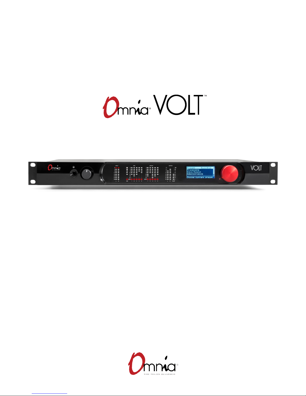
On-air excitement and ultra-clean sound,
in a versatile and convenient package
MULTI-USE AUDIO PROCESSOR
INSTALLATION AND USERS GUIDE
Software Version 1.0, FM DSP|Core • April 2017
For Part Number: 2001-00439
Page 2
VOLT MANUAL
II
User Warnings and Contact Info
The installation and service instructions in this manual are for use by qualified personnel only.
To avoid electric shock, do not perform any servicing other than that contained in the operating
instructions unless you are qualified to do so. Refer all servicing to qualified personnel
This instrument has an autoranging line voltage input. Ensure the power voltage is within the
specified range of 100-240VAC. The ~ symbol, if used, indicates an alternating current supply.
This symbol, wherever it appears, alerts you to the presence of uninsulated, dangerous
voltage inside the enclosure – voltage which may be sufficient to constitute a risk of
shock.
This symbol, wherever it appears, alerts you to important operating and maintenance
instructions. Read the manual.
CAUTION: HAZARDOUS VOLTAGES
The instrument power supply incorporates an internal fuse. Hazardous voltages may still be
present on some of the primary parts even when the fuse has blown. If fuse replacement is
required, replace fuse only with same type and value for continued protection against fire.
WARNING:
The product’s power cord is the primary disconnect device. The socket outlet should be located
near the device and easily accessible. The unit should not be located such that access to the
power cord is impaired. If the unit is incorporated into an equipment rack, an easily accessible
safety disconnect device should be included in the rack design.
To reduce the risk of electrical shock, do not expose this product to rain or moisture. This unit is
for indoor use only.
This equipment requires the free flow of air for adequate cooling. Do not block the ventilation
openings on the rear and sides of the unit. Failure to allow proper ventilation could damage the
unit or create a fire hazard. Do not place the units on a carpet, bedding, or other materials that
could interfere with any panel ventilation openings.
If the equipment is used in a manner not specified by the manufacturer, the protection provided
by the equipment may be impaired.
Page 3

VOLT MANUAL
USA CLASS A COMPUTING DEVICE INFORMATION TO USER.
WARNING:
This equipment generates, uses, and can radiate radio-frequency energy. If it is not installed and
used as directed by this manual, it may cause interference to radio communication. This equipment complies with the limits for a Class A computing device, as specified by FCC rules, part 15,
subpart j, which are designed to provide reasonable protection against such interference when
this type of equipment is operated in a commercial environment. Operation of this equipment
in a residential area is likely to cause interference. If it does, the user will be required to eliminate
the interference at the user’s expense. Note: objectionable interference to tv or radio reception
can occur if other devices are connected to this device without the use of shielded interconnect
cables. FCC rules require the use of shielded cables.
CANADA WARNING:
“This digital apparatus does not exceed the Class A limits for radio noise emissions set out in the
radio interference regulations of the Canadian department of communications.”
III
“Le présent appareil numérique n’émet pas de bruits radioélectriques dépassant les limites
applicables aux appareils numériques (de Class A) prescrites dans le règlement sur le brouillage
radioélectrique édicté par le ministère des communications du Canada.”
CE CONFORMANCE INFORMATION:
This device complies with the requirements of the EEC council directives:
♦ 93/68/EEC (CE MARKING)
♦ 73/23/EEC (SAFETY – LOW VOLTAGE DIRECTIVE)
♦ 89/336/EEC (ELECTROMAGNETIC COMPATIBILITY)
Conformity is declared to those standards: EN50081-1, EN50082-1.
Page 4

VOLT MANUAL
Trademarks and Licenses
Omnia and Omnia VOLT are trademarks of TLS Corp. All other trademarks are the property of
their respective holders.
All versions, claims of compatibility, trademarks, etc. of hardware and software products not
made by The Telos Alliance which are mentioned in this manual or accompanying material are
informational only. The Telos Alliance makes no endorsement of any particular product for any
purpose, nor claims any responsibility for operation or accuracy. We reserve the right to make
improvements or changes in the products described in this manual which may affect the product
specifications, or to revise the manual without notice.
This document and its content are copyrighted by TLS Corporation and may not be copied,
reproduced, or distributed in any form without expressed written permission.
Certain libraries are licensed to You under the terms of the GNU General Public License, Version
2 (“GNU GPL”). Telos is not allowed to sub-license these libraries to You as You are deemed to
have Your own direct license from the original licensee. Telos does not modify these libraries in
any way. Telos hereby offers to You, upon Your request and for the actual costs of materials and
shipping, all source code and object code files for all such GNU libraries contained in the Software. Copyright (C) 1989, 1991 Free Software Foundation, Inc., 59 Temple Place, Suite 330,
Boston, MA 02111-1307 USA. Everyone is permitted to copy and distribute verbatim copies of
this license document, but changing it is not allowed.
IV
Links to the GNU GPL and other modules used under license can be found in the About screen of
the VOLT Remote Control web interface.
Updates
Omnia VOLT’s features and operations are determined largely by software. The Telos Alliance
strives to provide the most stable and feature-rich software available. We encourage you to check
for software updates from time to time by visiting our website or by contacting us directly.
Feedback
We welcome feedback on any aspect of our products or this manual. In the past, many good
ideas from users have made their way into software revisions or new products. Please contact us
with your comments or suggestions.
Page 5

VOLT MANUAL
We support you…
By Phone/Fax
You may reach our Omnia Support Team in emergencies by calling +1 (216) 622-0247. For
billing questions or other non-emergency technical questions, call +1 (216) 241-7225 between
9:00 AM to 5:00 PM USA Eastern Time, Monday through Friday.
By Email
Non-emergency technical support is available at [email protected].
By Web
The Omnia Web site has a variety of information that may be useful for product selection and
support.
The URL is TelosAlliance.com/Omnia.
V
SERVICE
You must contact Telos Alliance before returning any equipment for factory service. We will
need your unit’s serial number, located on the back of the unit. We will issue a return authorization number, which must be written on the exterior of your shipping container. Please do not
include cables or accessories unless specifically requested by the Technical Support Engineer.
Be sure to adequately insure your shipment for its replacement value. Packages without proper
authorization may be refused. US customers, please contact Telos Alliance Technical Support at
+1 (216) 622-0247. All other customers should contact local representative to make arrangements for service.
WARRANTY
Did you know that all Telos Alliance products come with a 5-Year Warranty?
This product is covered by a five year limited warranty, the full text of which appears at the end
of this manual.
Page 6

VOLT MANUAL
REGISTER YOUR PRODUCT
Take a moment to activate your coverage online at: TelosAlliance.com/product-registration/
The Telos Alliance
1241 Superior Ave. Cleveland, OH 44114 USA
+1 (216) 241-7225
For Omnia Support:
24/7 telephone +1 (216) 622-0247
Email [email protected]
Web TelosAlliance.com/support-request
VI
Page 7

VOLT MANUAL
Table of Contents
VII
0 User Warnings and Contact Info II
REGISTER YOUR PRODUCT . . . . . . . . . . . . . . . . . . . . V
A Letter from our CEO, Frank Foti . . . . . . . . . . . . . . . . .VII
1 Omnia VOLT Overview 1
2 VOLT in a hurry! 5
Step-by-step quick installation . . . . . . . . . . . . . . . . . 6
3 Installation and Rear Panel 8
Physical Installation . . . . . . . . . . . . . . . . . . . . . . 8
Hookup . . . . . . . . . . . . . . . . . . . . . . . . . . . . 9
4 Front Panel and LCD 14
Front Panel Meters . . . . . . . . . . . . . . . . . . . . . . . 15
Using the Jog Wheel . . . . . . . . . . . . . . . . . . . . . . 16
VOLT Front Panel Menu Map . . . . . . . . . . . . . . . . . . . 19
5 Browser-based Remote Control 21
Logging In . . . . . . . . . . . . . . . . . . . . . . . . . . . 21
Remote Screen . . . . . . . . . . . . . . . . . . . . . . . . . 24
Remote Control Map . . . . . . . . . . . . . . . . . . . . . . 27
6 VOLT Processing 28
Preset strategy and tuning . . . . . . . . . . . . . . . . . . .28
Processing Block Diagram . . . . . . . . . . . . . . . . . . . .32
VOLT Processing Terminology . . . . . . . . . . . . . . . . . .33
7 Troubleshooting and Updates 35
Contacting Us…. . . . . . . . . . . . . . . . . . . . . . . . 35
8 Technical Specications 36
9 5-Year Warranty 38
Page 8

War of the Waves
Dear Valued Customer,
It’s with great pride and a tip of the hat to an incredible team that I congratulate you on your new Telos
Alliance product. Everything we do here at the radio division of the Telos Alliance is with one end goal
in mind: To help broadcasters declare victory in extremely competitive environments. By purchasing
this product from us, in essence, you have declared war on your competition.
After all, the majority of Telos Alliance employees were broadcasters themselves once, and the products
we’ve developed over the years have been designed as solutions to specific issues faced on the front
lines of our industry. We’re right there in the trenches with you and have the weapons you need in your
arsenal.
Telos Systems is a catalyst to out-of-this-world sound, with the most powerful and popular broadcast
telephone systems in the industry; IP/ISDN codecs and transceivers; plus processing/encoding for
streaming audio. We built an industry on the back of these amazing telephony systems, and they are still
going strong.
While we at the Telos Alliance never forget our roots, we are also blazing trails in terms of new technologies like stream-encoding and AoIP, so that all types of broadcasters can excel in this ever-evolving digital
world.
Omnia Audio not only lets you stand out on the dial with your unique signature sound via legendary
audio processors, audio codecs, and microphone processing, it lets you give your listeners a better
streaming experience across devices with innovative stream encoding/processing software and hardware.
Axia Audio is a driving force behind the AES67 AoIP standard, and its networked AoIP radio consoles,
audio interfaces, networked intercom, and software products continue to move AoIP adoption forward
and help broadcasters streamline operations with cohesive, smart, and feature-rich AoIP ecosystems.
Last, but certainly not least, 25-Seven has traditionally been known for its audio delays, but its Voltair
watermark monitor/processor has made a name for itself more recently as the disruptive product that
helped broadcasters take back their ratings and harness the true power of their listening audiences.
You work so hard on your programming day-in and day-out, it deserves technology that will optimize
sound and performance at every point in the airchain and online. Armed with Telos products, you have
what you need to set your competition squarely in your crosshairs.
With that, I’ll leave you to prep your armaments. I hope that you will enjoy your Telos Alliance products
for many years to come!
Sincerely,
Frank Foti
CEO, The Telos Alliance
Page 9

1
1
Nobody knows processing like Omnia…
For more than thirty years, we’ve been at the front of broadcast audio processing. In that time
Omnia has earned a reputation for market-leading loudness and a clean, undistorted on-air
sound.
…and nobody knows broadcast DSP like Telos
We’ve also been Digital Signal Processing pioneers, introducing the first DSP-based Telephone
Talk Show system, the Zephyr ISDN codec, and the first all-digital FM airchain processor.
And we’ve continued to lead, with Axia—the first AoIP audio and control networking system designed specifically for broadcasters, with our ground-breaking Voltair watermark enhancement
systems, with our Linear Acoustic loudness and surround management products, and more.
Though it all, we’ve maintained one goal for Omnia: to apply cutting-edge technology, that can
give your station a competitive, exciting, market-leading sound that gets and holds listeners.
Now, with Omnia VOLT, we’ve gone even further!
Omnia VOLT Overview
We’ve rewritten the rules for broadcast DSP, fine-tuning our algorithms to bring you:
♦ Unprecedented processing power and sound in a one-rack-unit package,
♦ Easy setup without sacrificing your ability to customize exactly the sound you want, and
♦ Future-proof versatility.
Omnia VOLT is… a signal that jumps out of listeners’ radios. With the pristine, warm
Omnia sound broadcasters love.
♦ A new generation Frank Foti-designed Clipper for stronger on-air sound without grunge.
♦ Six Separate AGC Sections: One wideband, plus five separate time-aligned narrow band
sections, each with separate controls for every important parameter. Plus a tunable midband crossover. Give your station the loudness and consistent sound you want!
♦ Five Separate Time-Aligned Limiter Sections, each with separate Drive, Hold, Threshold,
and Attack/ Decay controls. They give you protection against overmodulation while
maintaining a loud signature sound.
Page 10

OMNIA VOLT OVERVIEW
♦ Variable Deep Bass, Phat Bass, and Warmth enhancers. Get that meaty Omnia sound,
fine-tuned the way you want.
♦ Bass Pre-Clipper. Fully adjustable with Tightness and Girth controls. You’ll have strong,
listener-pleasing bass without worrying about intermodulation distortion.
♦ Clipper Silk adjustment. If your format is prone to treble distortion, you can add just
enough Silk to clean up those high frequencies.
♦ Sensus processing for digital program streams. Omnia’s exclusive Sensus algorithms
actually predict how HD, DRM, or multicasting data reduction will affect your sound. They
pre-condition your signal, making compression sound better—even at low bitrates.
♦ Adjustable BS-412 Threshold and Processing for full compliance with ITU standards.
♦ Stereo Enhancement for FM Analog, without adding multipath. You’ll get a wider, more
exciting signal that jumps out of the radio.
♦ Variable high-pass and switchable phase rotator. Those ultra- low frequencies, too low to
be perceived as bass by listeners, won’t rob you of on-air power.
♦ Automatic mono “dry voice” sensing. Ideal for FM Analog Stereo stations using extreme
processing: it keeps an extra hand on the clipper, to stop distortion when the L+R channel
gets boosted by mono signals.
CHAPTER 1
| 2
Omnia VOLT is… fast setup and ease-of-use, while giving you absolute control of
every important parameter.
We’ve built VOLT for users who need to get results fast, and for those who like to customize
their station’s sound. You can get VOLT on the air in minutes, select presets that have been
designed for today’s stations and programming, create a unique sonic personality with just a few
nudges of the QuickTweak™ sliders, fine-tune it with a comprehensive Graphic User Interface,
save settings for your automation to trigger at different dayparts, and share those presets with
other VOLT users in your group.
♦ Choose from some of the best factory presets on the air. They’re designed by Omnia’s
processing experts, and by our favorite “insider” guest programmers.
♦ Then use Omnia VOLT’s exclusive QuickTweak system, to fine-tune your sound fast.
Get exactly the processing you want, while you’re on the air, right from the front panel or a
connected computer.
¸ Nobody knows processing like Omnia. We’ve designed QuickTweak based on our
decades of experience. It links complex and interactive parameters—some of which can’t
be reached by normal processor controls—to create a core set of “meta” controls.
Page 11

COR E
DSP
OMNIA VOLT OVERVIEW
¸ QuickTweak is easy to understand: controls are intuitive, you can tune them by ear, and
you hear the results instantly.
¸ You can use QuickTweak on the factory presets, or on your own custom processing.
¸ You can save your own preset file after using QuickTweak, and recall it instantly.
¸ You can continue to QuickTweak or fine-tune your settings, even you’ve saved a file, if
your needs change or you want to refine the sound.
¸ Customize a unique sound for your station and market. Omnia VOLT’s Graphic User
Interface is easy to navigate, but gives you the deep level of control you need.
Omnia VOLT is future-proof versatility, at no extra charge!
CHAPTER 1
| 3
♦ VOLT’s DSP|Core firmware modules let you rearrange and modify VOLT’s internal
architecture, as your needs change:
♦ Use VOLT for FM Analog Stereo at the station, with high-quality baseband clipping to feed
uncompressed STLs, or at the transmitter, with dual composite outputs.
♦ Use VOLT for AM Broadcast, with purpose-built presets for the challenges of AM radio.
VOLT’s Tunable Asymmetrical Modulation and Tilt help you get modern results, even
from older transmitters!
♦ Use VOLT for Studio and Multicast for HD/DRM/Web and other compressed media, plus
program and syndication production. Our exclusive Sensus algorithms reduce compres-
sion artifacts even at low bitrates.
♦ Use VOLT Stereo Generator when you need to split your system between a main processor at
the station, and a dedicated MPX stereo generator at the transmitter site.
♦ Use VOLT with Low-latency FM to comply with local regulations, using a high efficiency
clipper that’s optimized for less than 7 ms latency.
DSP|Cores aren’t extra cost add-ons!
♦ Download the DSP|Core firmware package you need for free, from Telos’ website…
♦ Transfer it to your VOLT from any network computer, and…
♦ Reboot. It’s that simple!
Page 12

OMNIA VOLT OVERVIEW
CHAPTER 1
| 4
You can switch applications whenever your needs change. Or keep a spare Omnia VOLT as
backup for every one of your standby processors, in all your stations!
DSP|Core is almost something for nothing! There are just two small caveats:
1. Some Omnia VOLT features aren’t applicable to every processing need. (Obviously, you
don’t need dual composite outputs on a processor you’re using for webcasting.) Each
DSP|Core firmware package has a feature set that’s fine-tuned for its application, and
allocates DSP where it’s needed most.
2. Some DSP|Core firmware modules are still being tested and refined while we introduce
others. Check our website for updates.
Omnia VOLT installs quickly, with setup and convenience features for today’s broadcaster:
♦ VOLT includes a built-in HTML-5 server for full control from any computer, tablet, or
smartphone… it doesn’t need Java or special plug-ins, so there’s no worry about those
vulnerabilities.
♦ Totally flexible signal path. You can choose analog, AES/EBU digital, or Livewire inputs;
choose which channel to use for mono inputs; use analog, AES/EBU digital, Livewire, or
composite outputs… or all the outputs at the same time. There are separate volume and
channel balance trims, and flexible “flip-phase options”, on each input. You can save and
recall custom input/output setups for different applications.
♦ Switchable insert points for Voltair, watermark encoders, or other downstream encoding.
You can feed encoders with a pre-processed signal from VOLT’s multiband AGC and
limiters. That way, your encoder sees a stronger, more reliable signal. Then feed the
encoder’s output back into VOLT, for post-encoding clipping that protects you against
overmodulation.
♦ Automatic “failover” signal switching. You can specify a backup input for use if your main
signal drops outs. VOLT can switch to this source automatically, with adjustable sensitivity, or you can trigger the changeover via contact closure or Livewire GPIO as needed.
♦ Rugged one-rack-unit construction fits any control room, technical center, or transmitter
shack, with easy-to-see LED meters.
♦ Fanless operation. Feel free to use VOLT near critical monitoring or live mics.
♦ Flexible Pre-Emphasis Switching on both input and output. This makes it easy to fit VOLT
into any existing airchain.
♦ Built-in tone generator. It lets you verify meter readings and signal path quickly.
♦ In addition, the FM Stereo Generator DSP|Core provides:
♦ Dual Variable Composite Outputs to feed a main and backup transmitter.
♦ Variable Pilot Level and Phase let you adjust the signal for transmission.
♦ Adjustable SCA input for additional services, with 19 kHz sync output to synchronize
external generators.
Page 13

COR E
DSP
5
2
We understand there are times you need to get equipment up and running quickly, and don’t
have time to learn all it can do1. This chapter is for those times.
VOLT is a fully tunable and sophisticated processor that can be set up for AM or FM, analog or
digital broadcasting, Web and other compressed media, or studio and program production.
♦ With VOLT, you can achieve a market-leading sound using just our factory presets.
♦ Then you can customize the sound easily, right from the front panel,
the ones you like as your own personal presets.
♦ But VOLT also lets you go deep. More than 140 easily accessible and interactive processing
and routing adjustments let you get just the sound you want. They let you choose, balance,
and condition input signals from analog, AES/EBU digital, or Livewire sources. They allow
automatic “failover” signal switching if your main program source fails. They let you insert
watermark ID encoders and our Voltair watermark processor after your signal has been
processed for strength and reliability, but before the protection and loudness of VOLT’s
ultra-clean clipper.
VOLT in a hurry!
with our exclusive QuickTweak system: six intuitively labeled sliders,
designed by processing experts, each controlling specific aspects of your
sound—some of which can’t be adjusted by normal processor controls.
You can fine-tune them in real-time, hear the results as you do, and save
♦
stereo generator today… turn it into a fully featured digital streaming processor with
exclusive artifact-reducing Sensus processing tomorrow… change it to an ultimate AM
processor with sophisticated bass and asymmetry enhancement a day later… or use it for
ultimate control of studio or syndicated programming after that! Any VOLT DSP|Core
package can be loaded at any time, as your needs change.
1 In some stations, this may be the normal mode. So we build sophisticated devices that can be used quickly
and intuitively. But VOLT is also powerful and versatile: if you use this manual, you’ll learn all the other useful
things your new Omnia can do.
VOLT can even become totally different processors whenever your needs
change! Our five free, downloadable DSP|Core firmware packages re-allocate VOLT’s internal resources for your purpose. You can have an FM
analog processor with complete Omnia control and internal composite
Page 14

VOLT IN A HURRY!
CHAPTER 2
| 6
Omnia VOLT is a lot of processor. We couldn’t put all of it into an introductory, quick-start
chapter. To learn all it can do for you, you’ll have to read the rest of this book. (If you don’t have
enough time to do that, at least scan the table of contents, and see which chapters will be most
useful.)
Step-by-step
These dozen (or fewer, depending on setup) steps assume you’re running VOLT from its front
panel. There’s also an extensive Remote Control, described later in this manual.
1. Install VOLT in your rack, connecting audio input and outputs appropriate for your system.
2. If using the composite generator, connect one of the composite outputs to your exciter.
3. Connect AC power. There is no power switch. Wait for the system to stabilize and the LCD
to say Omnia VOLT.
4. Navigate to Input/Output > Input and select the appropriate Input Src.
5. Feed regular program material at your station’s normal level (usually 0 VU on the console
meters). Adjust VOLT’s appropriate Level so its input LEDs bounce up to -16 or -12. Exit
back to Main Menu.
6. If you’re using an audio-input monitor, transmitter, or STL, navigate to Input/Output
> Output and adjust the appropriate Level for the next device. Exit back to Input/
Output.
7. Navigate to Output > FM Options, and select the FM Pre-emph (pre-emphasis) setting
required for your country or region.
♦ If BS-412 power limiting is required, turn it on in this menu.
♦ If you’ve chosen an audio-frequency input device in step 6, select the appropriate De-emph
for that device’s signal.
♦ If you’re feeding an uncompressed digital STL, or want to use an audio output to feed the
exciter, turn De-emph off for that output. This means VOLT’s FM Pre-emph, selected at
the start of this step, stays as part of the signal to the STL.
VOLT should be the only device providing pre-emphasis or limiting. This means you should
disable any additional pre-emphasis or limiting in the exciter.
8. If you’re using a composite output, navigate to Input/Output > Stereo Generator, then
adjust Comp 1 or Comp 2 for 100% modulation, and Pilot Lvl for between 8% - 10%. Exit
back to Main Menu.
9. Navigate to Processing > Preset, feed normal program material, and choose a preset for
your initial setup. You’ll be able to change the preset and/or fine-tune its settings later.
Page 15

VOLT IN A HURRY!
CHAPTER 2
10. Navigate to QuickTweak > Clip Drive and set the drive for the best compromise between
loudness and distortion. You’ll be able to refine this adjustment in many ways, later. Exit
back to Main Menu.
11. Navigate to Save Preset, and provide a name for the settings you just created. This can
serve as a baseline while you do step #12:
12. Read the rest of this manual. Learn how to shape your sound with the best Omnia processing for your station and market. Take the time to experiment, and enjoy the results!
| 7
Page 16

8
3
Installation and Rear Panel
Physical Installation
Studio or Transmitter?
Obviously, if you’re using VOLT’s internal stereo generator with composite output, it should be
close to the transmitter(s)2. All operating functions can be controlled easily over a network, so
you’ve got complete flexibility to tune a transmitter’s VOLT from the studio.
But if you’re planning to locate VOLT at the station and feed Left / Right audio (with no subcarrier) to a transmitter via STL, make sure the STL is linear, and does not use data reduction
or compression. This may be non-intuitive: after all, today’s best compressed STLs can sound
pretty good. The problem is that lossy compression algorithms are designed for normal, unprocessed speech and music in normal listening situations. VOLT optimizes your signal for transmission, and the clipper is designed to create maximum loudness with minimum distortion
when broadcast. This can create waveforms that sound great on the air… but break the lossy
compression schemes in some STLs. The result that the STL will create extra distortion and lack
of clarity, before the signal even gets to the transmitter.
This warning also applies to HD and DRM transmission using VOLT’s Multicast DSP|Core. Our
exclusive Sensus processing can actually eliminate some of the distortions of those compressed
media. But “double compression”—first, through a lossy STL, and then through a compressed
digital media transmitter—can create unpredictable interactions that even Sensus can’t fix.
Increasingly, facilities with high bandwidth ber links between their studios and transmitter sites
are discovering that Livewire AoIP can be used for high reliability, lossless STL. It lets you feed
a VOLT at the transmitter using Livewire Xnode at the studio, or use VOLT at the studio to send
processed AoIP audio to the transmitter. The Livewire capability built into every VOLT lets you take
advantage of today’s faster and cheaper IP bandwidth, with ever-increasing STL options.
2 VOLT has two separately adjustable composite outputs, so you can drive a main transmitter and backup
simultaneously.
Page 17
INSTALLATION AND REAR PANEL
CHAPTER 3
| 9
Rack mounting
VOLT is only one rack unit high, and can mount almost anywhere.
Like most sophisticated equipment, it can be damaged by extreme heat.
♦ Do not mount it directly above or below equipment that normally runs warm. For best
air circulation, make sure whatever is mounted below it is very shallow: a blank panel, or
something like a patchbay that doesn’t generate heat.
♦ Do not block the ventilation grills on VOLT’s sides. There should be at least an inch of air
space on both sides of the unit. Most racks provide this.
♦ Do not block the ventilation holes on VOLT’s back.
There’s a lot of electronics in VOLT’s chassis, so it has to be fairly deep: about 11½” plus connectors. While it’s not particularly heavy, that depth has to be cantilevered by the one-unit front
panel: To prevent damage to the front panel, always mount with four rack screws. If you must
use only two screws temporarily, use both bottom screw holes. That distributes the weight better.
Live studio?
VOLT does not have an internal fan, and can be located near a live mic. This makes our Multicast
DSP|Core version ideal for high quality podcasting and other small operations.
Hookup
Audio connections
We designed VOLT’s audio routing to be extremely flexible:
♦ You can connect VOLT via balanced analog, AES/EBU digital, or Livewire AoIP. Each
input can have a different program stream, and you can select which input gets broadcast
on the front-panel LCD or from a connected computer. You can also designate one input
for automatic or manual “failover” backup of the same programming, if the main link is
disrupted.
♦ Each input and output can be adjusted independently: you can set any level between -12
and +12 dB of nominal, or trim the channel balance ±3 dB, in precise .1 dB steps.
♦ Each input can also be adjusted independently for polarity3 with normal or inversion on
either or both input channels. Input signals can be independently set for normal L/R or
flipped R/L stereo, or mono from either channel or both summed.
3 Sometimes referred to as “phase”.
Page 18

INSTALLATION AND REAR PANEL
CHAPTER 3
| 10
Insert Point
Normally, all of VOLT’s audio outputs will carry the fully processed output. You can use them to
distribute analog to nearby monitors, for example, while sending digital audio to a control room
via AES/EBU or Livewire.
However, you can also break VOLT’s internal signal path for use with a third party watermark
identification or EAS generator, or for our 25-Seven Voltair watermark enhancement and management system.
♦ The external device will be fed from VOLT’s multiband Limiter, after all enhancement and
AGC. This way, watermark encoders can take advantage of Omnia presets that boost the
critical frequencies for electronic ratings systems.
♦ The external generator or Voltair output is applied directly to VOLT’s drive control of the
final clipper or limiter4. This way, you don’t have to worry about an encoder’s added signal
driving your transmitter into overmodulation.
VOLT’s insert output becomes the “send” for your external device, and can be any one of
VOLT’s three audio outputs. The insert input (“return” from the external device) can be any
input you’re not using for program stream or failover backup. Insert input and output don’t have
to be the same mode—one can be analog, for example, while the other is AES/EBU—though this
rarely occurs in practice.
Insert points are designated using VOLT’s network Remote Control. See that chapter for details.
Analog connections
These are balanced input and output, +4 dBu nominal. At nominal level, there is +18 dB headroom available.
Inputs can be fed from any transformer or electronically balanced sources. The input impedance
is 10kΩ. Outputs are electronically balanced, for any load of 600Ω or higher.
We do not recommend using VOLT in an unbalanced environment. If you must hook it up to
unbalanced equipment, use a buffer amp or transformer.
Connectors are standard XLR-3 male and female: pin 1 ground, pin 2 “hot”, pin 3 return.
AES/EBU connections
Input is stereo, transformer isolated and balanced 110Ω nominal per AES/EBU standard, with 24
bit resolution. Input automatically locks to any sample rate between 32 kHz and 108 kHz.
Output is stereo per AES3 professional standard, transformer isolated and balanced 110Ω
nominal. Output sample rate can be locked to the input, locked to an external sync source, or
use VOLT’s internal 48 kHz clock. AES/EBU output level is -18 dBFS nominal; like all VOLT’s
outputs, it can be adjusted over a 24 dB range.
4 Depending on which DSP|Core version is loaded.
Page 19

INSTALLATION AND REAR PANEL
CHAPTER 3
| 11
Connectors are RJ-45 female, EMI-suppressed and wired according to StudioHub+® standard.
AES/EBU program input and output appear on pins 1+2 of the corresponding RJ-45, with pin 4
as ground. StudioHub+ adapters are included with VOLT5: use the XLR connectors with a green
color sleeve.
If you want to apply an external sync signal for AES/EBU, use pins 3+6 of the input RJ-45; this
is the XLR female with a red color sleeve on our adapter. Sync source should be an AES/EBU
stream (often called “digital black”); VOLT does not sync to an unbalanced 75Ω word clock.
Livewire
Connect a Livewire Audio-over-IP network to the Livewire/LAN RJ-45 jack. Livewire must be
configured from a connected computer; see the chapter on Remote Control.
Don’t Know Jack?
StudioHub+ inputs and outputs, and Livewire or Ethernet LAN, all use identical RJ-45 connectors. You
can’t tell which is which by feel. Before connecting, look at the back-panel silk screening or the photo
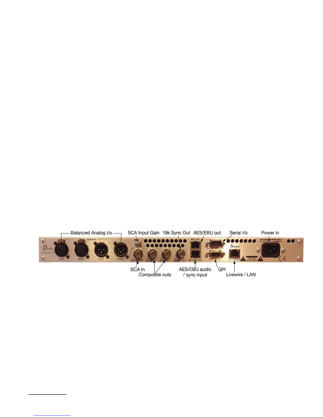
in this chapter to make sure you’ve got the right one.
Composite connections
These are usable only if your VOLT is running an FM or FM Stereo Generator DSP|Core.
Composite Outputs
These are identical 75Ω outputs to feed a multiplex signal to your transmitter(s). Each is separately adjustable from 0 V to 10 V pp in .5v steps. Pre-emphasis curve and mode, pilot level and
phase, and stereo separation are also adjustable. See the chapter on Remote Control for details.
SCA Input and Gain
This 75Ω input can be used for Subsidiary Communications (SCA) such as reading for the blind
or data casting. A signal from an external SCA or RDS generator, at this input, is mixed into both
composite outputs.
The Gain trimmer lets you adjust between -29 dB and +2.6 dB, accommodating signals between
10V and .25 V p-p for 8.6% injection on a 3.6 V composite output.
19k Sync Out
This is a TTL-level 19 kHz square wave, locked to VOLT’s stereo pilot, for use as a reference for
most RDS or SCA generators that operate at multiples of the 19 kHz pilot frequency.
5 Get additional adapters from your local dealer or http://www.radiosystems.com. Some stations prefer to run
AES/EBU over Cat-5 or Cat-6 cables with RJ-45; full connection details are at http://www.studiohub.com.
Page 20

INSTALLATION AND REAR PANEL
CHAPTER 3
| 12
Data Connectors
Serial I/O
This is a DB9-M for factory maintenance; it is not used in normal VOLT operation.
GPI
This is a DB9-F for remote control input, using contact closures or other logic-level systems.
Pin 1 +5VDC Out
Pin 2 Input Common +
Pin 3-6 Trigger input #1 - #4
Pin 7,8,9 GND
The action for each input is controlled by the GPIO/Events tab in the Remote Control.
If using pushbuttons or relays, each GPI activates by momentarily connecting its Trigger input
to Ground, while pin 1 is tied to pin 2. (For noise immunity, you may wish to pull the input line
“normal high” by connecting it to the +5V supply through a 1kΩ resistor.)
If triggering from a logic source, the source’s continuous positive voltage should go to pin 2, and
each output should pull its corresponding input pin low when active. Systems using TTL levels
can be connected directly. Systems working at higher voltages will require a dropping resistor in
series with each input:
Input Voltage Required Resistor
5 VDC none
6 VDC none
12 VDC 680Ω, ¼ Watt
24 VDC 1.8kΩ, ½ Watt
48 VDC 3.9kΩ, 1 Watt
The source must be capable of providing up to 40 mA.
General Purpose Outputs are available only at the Livewire connector.
LIVEWIRE / LAN
This is an RJ-45 for 10Base-T and 100Base-T Ethernet connection. It can be used for Livewire
audio, remote control with a connected computer, or both. See Livewire and Remote Control
chapters for details.
Page 21

INSTALLATION AND REAR PANEL
CHAPTER 3
| 13
Power Connector
VOLT automatically adapts to 50 or 60 Hz power at any voltage between 90 – 240 VAC. Nominal power is 1A at 110 V, .5A at 240 V. Actual consumption is around 15 watts during normal
operation.
VOLT should be connected to a grounded outlet, according to local codes. VOLT does not have a
power switch, but may be installed in a rack with switched power.
Page 22
Headphone
Gain Reduction
Output
LCD Jog
Input level
Wideband
Individual Bands
out volume
AGC Limiter
Mid
MidHi
Low
MidLo
Hi Mid
MidHi
Low
MidLo
Hi
11 Gate LEDs
(etc)
CompositeLeft
Right
Power
14
4
Front Panel and LCD
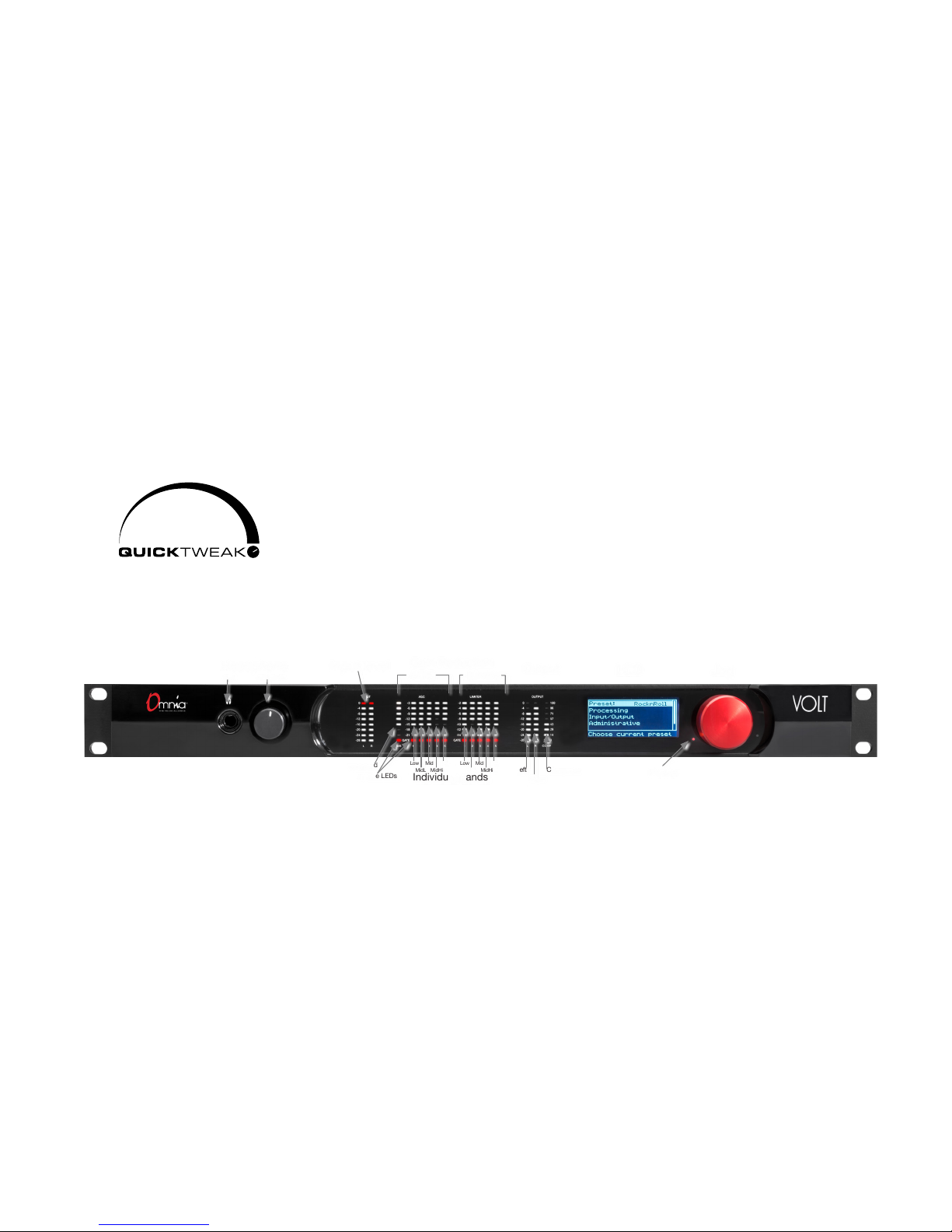
You can get VOLT operational, select a preset, and flexibly adjust it for your station’s sound and
market …in minutes… entirely from the front panel!
Omnia’s exclusive QuickTweak system lets you completely customize
important internal processing parameters, including some that can’t be
reached through normal processing controls, with “master controls”
designed specifically for broadcast processing. Choose any preset. Use
QuickTweak to fine-tune its density, spectral balance, stereo soundstage,
clipping, and more. You can hear the results as you adjust the six QuickTweak controls… and
then can name and save your customized “tweak” as a new preset.
All of these front-panel functions, and more, are accessible via password-protected login from
networked computers, tablets, or smartphones. There are more than 140 individual routing and
processing adjustments and selections available there, along with comprehensive higher resolution metering, preset management, firmware update, DSP|Core installation, and maintenance
functions. See the chapter on Remote Control.
Front Panel Headphone Jack
VOLT’s ¼” TRS stereo headphone jack monitors the processed signal. It is driven by a separate
high quality DAC and amplifier, independent of the analog XLR outputs. It has a separate volume control on the front panel.
Page 23

FRONT PANEL AND LCD
How are they listening?
You can use headphones to verify signals or as a rough check on VOLT’s processing. But we don’t
recommend using phones for ne-tuning your station’s sound… In our experience, dynamics perceived through headphones are dierent from those heard over speakers, and adjustments made
over headphones may be too subtle for loudspeaker use.
For critical adjustments, listen to VOLT through high quality monitors in a studio situation. Or though
speakers roughly equivalent to how your listeners will be hearing the station: some processing gurus
do their most critical tuning while sitting in their cars! Don’t rely on headphones for ne-tuning,
unless you’re sure the listeners are using headphones as well.
CHAPTER 4
| 15
Front Panel Meters
VOLT’s left-most two meters are Left and Right processor input, with LEDs stepped from -28
to 0dBFS. These behave like standard digital level meters. The top (red) LED lights when the
signal reaches -0.05 dBFS or higher.
The next 11 meters read the Gain Reduction [“GR”] in each of VOLT’s AGC and Limiter
sections, calibrated between -3 and -24 dB. The bottom LED of each stack lights when that
section’s Gate is activated. There are 6 AGC meters (wideband, then the five individual frequency bands), and 5 Limiter meters (one for each frequency band).
About GR Meters
The operation of a Gain Reduction meter might seem backwards, compared to the normal meters
on consoles and ampliers. When an AGC or limiter’s input signal is soft, the gain control algorithm
doesn’t need to lower the gain: only the top LED will be lit, showing 0 dB reduction. As the signal gets
louder, more reduction is applied, so LEDs below the top one start to light up. The meter “lls downward” as volume increases.
These GR meters let you see how VOLT is conditioning your signal levels in real-time. The amount
of Gain Reduction at any moment depends on your signal… as interpreted by multiple parameters
provided by the preset, the QuickTweak controls, individual processor settings on the remote control,
and of course the nature of Omnia’s algorithms.
Experienced operators keep one eye on the GR meters and both ears on the loudspeakers while
adjusting a station’s sound.
The right-most three meters indicate output levels for the Left and Right channels (calibrated
from -28 to 0 dBFS), and for the composite output (calibrated 0 to 100%).
Page 24
FRONT PANEL AND LCD
CHAPTER 4
| 16
Meter Screens
There are 3 other meters available on the LCD. They can be activated by holding the Jog wheel in
for more than one second. The S meter displays Stereo Enhancement, calibrated from 0 to 100%.
The B and M meters show Gain Reduction through the Bass and Main clippers, and are calibrated
between -24 and 0 dBFS.
If the LCD meters are showing, turning the Jog Wheel to the right brings up a Livewire Status
page with indicators for Link and Sync.
Tap the wheel to change the LCD back from meter or status mode to its normal menus.
All of VOLT’s LED and LCD screen meters also appear when needed, in higher resolution, on
the Remote Control.
Using the Jog Wheel
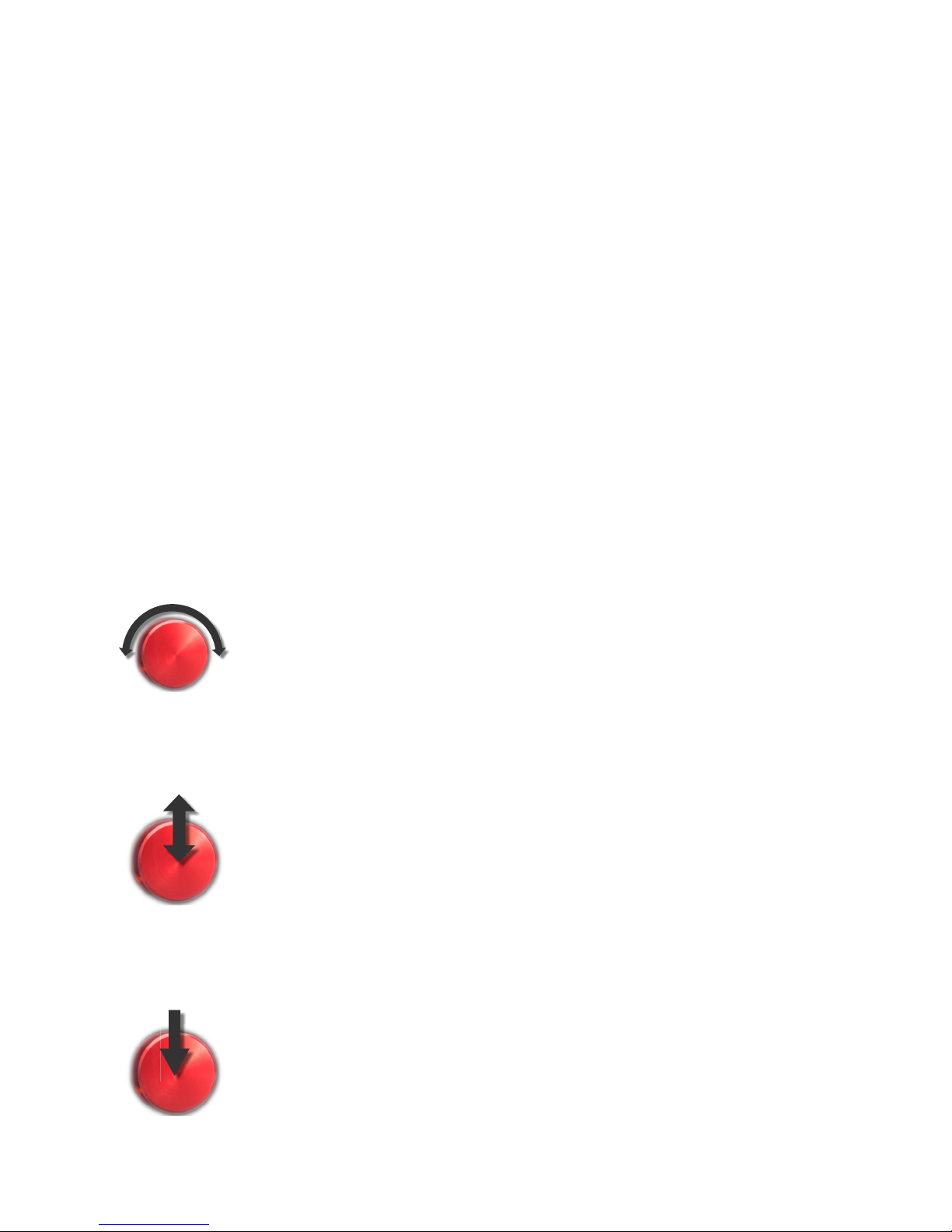
The big red Jog wheel is a multi-function encoder. It lets you control selections and input text or
numbers on VOLT’s LCD screens. You can use it in three distinct ways:
Turn the wheel
Tap the wheel
Press and hold
Rotating the wheel clockwise moves the highlighted selection on the LCD
downward through menu options, or to the right through fields where you can
enter numbers or text. When you’re in one of those fields, the wheel scrolls
through possible letters or numbers. Rotating it counter-clockwise does the
reverse.
If you press the wheel in until it clicks, then quickly release it, the highlighted
selection or field becomes active. This confirms a menu choice or option. If you
do this in an entry field, you can then turn the wheel to select a value for that
field. When an entry field shows the value you want, tap again to set it. Then
the wheel returns to normal scrolling.
If you hold the wheel in for more than two seconds, and then release it, the
LCD switches between menu/entry and meter screens. Meter screens add
functions beyond VOLT’s 16 front panel LED meters, and are described in the
section immediately above.
Page 25
Input/Output
Processing
Administrative
Lock Front Panel
Input/Output
Menu choices
Scroll bar
Selected choice
Hint or Description
Mono Mode
STEREOInput Mode
LW Level 0.0dB
Right Trim 0.0dB
Invert None
Slider value
Text Choice
FRONT PANEL AND LCD
CHAPTER 4
| 17
Navigating LCD Menus
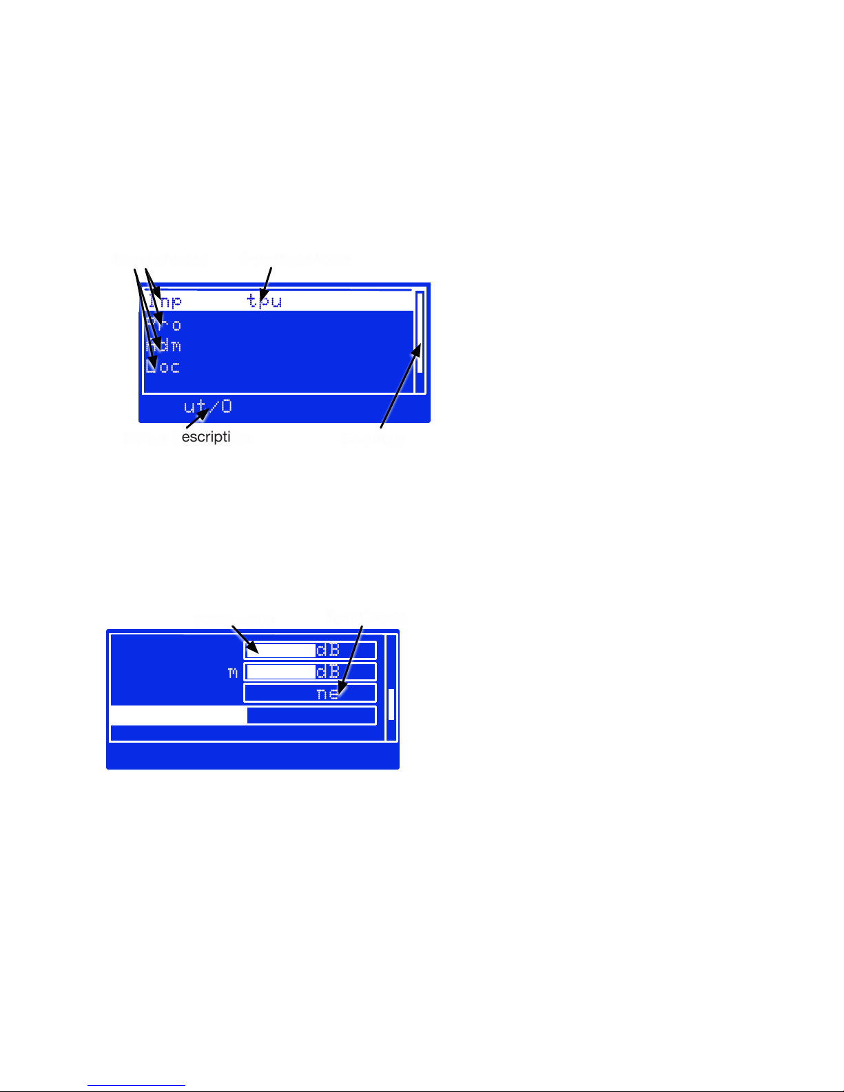
The Jog wheel lets you navigate around front panel menus, make selections, and adjust values. A
screen might display possible submenus, like this one:
In this example, you’d turn the wheel to highlight one of the lines. If there are more choices
than can be displayed at once on the screen, a scroll bar helps you keep track of vertical progress
through the choices.
When your selected choice is highlighted, tap the wheel to enter that submenu.
Or a screen might let you choose values, like this one:
The LW Level and Right Trim above are typical sliders. When one of them is selected, tap
the wheel to adjust its value. Then turn the wheel to raise or lower the value, on the screen that
appears. When you’re satisfied with the change, tap again to return to the previous menu.
Invert and Input Mode on the above are text choices. Select and tap, to bring up a screen where
you can scroll through the possible values. Tap again to return to the previous menu.
Page 26

FRONT PANEL AND LCD
CHAPTER 4
| 18
About Text and Numeric Entry
A few of the simpler text choices present both options on the menu. Select the line for that
choice, tap, turn the wheel to select an option, and tap again to confirm.
Some menu choices allow free entry of text (as for a preset name) or numbers (such as an IP
address):
Tap on the parameter (e.g., Name) and the highlighted cursor will go to the space next to
it. Tap again to select that space, and then turn the wheel to scroll through the available
alphabetic or numeric characters for that space. When you get the one you want, tap to
confirm that character and scroll to move to the next space. Tap on that space, turn to scroll
through characters, tap to confirm, scroll to the next, and so on.
When the complete name or number has been entered, tap again to go to the next field.
Then don’t tap again; instead, turn the wheel to select other options on that screen (usually
Save or Cancel). After you tap to select one of those options, the system will bring you
back to the previous menu.
Preset names and passwords can be up to 16 characters long, alpha-numeric. Special characters
and spaces are not allowed; underscore can be used to separate words.
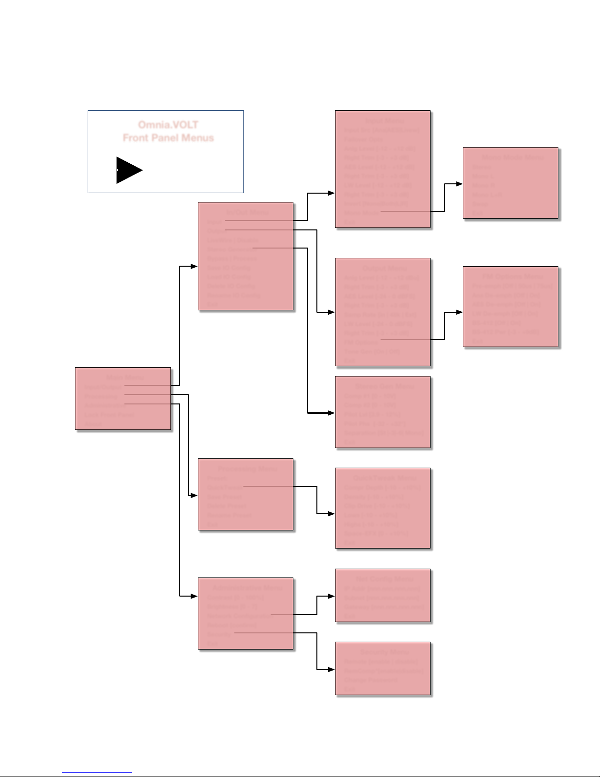
Volt Front Panel Menu Map
Most of the Front Panel Menu functions are self-explanatory. When a hint is needed for any
particular menu entry, it appears on the bottom line of the LCD when that entry is highlighted.
If a feature requires more explanation, a warning and confirmation screen appears when you tap
its entry.
Page 27
Main Menu
Input/Output
Processing
Administrative
Lock Front Panel
About
In/Out Menu
Input
Output
LiveWire | Disable
Stereo Generator
Bypass | Process
Save IO Config
Load IO Config
Delete IO Config
Rename IO Config
Exit
Input Menu
Input Src [Ana|AES|Livew]
Failover Opts
Anlg Level [-12 - +12 dB]
Right Trim [-3 - +3 dB]
AES Level [-12 - +12 dB]
Right Trim [-3 - +3 dB]
LW Level [-12 - +12 dB]
Right Trim [-3 - +3 dB]
Invert [None|Both|L|R]
Mono Mode
Exit
Output Menu
Anlg Level [-12 - +12 dBu]
Right Trim [-3 - +3 dB]
AES Level [-24 - 0 dBFS]
Right Trim [-3 - +3 dB]
Samp Rate [in | 48k | Ext]
LW Level [-24 - 0 dBFS]
Right Trim [-3 - +3 dB]
FM Options
Tone Gen [On | Off]
Exit
Stereo Gen Menu
Comp #1 [0 - 10V]
Comp #2 [0 - 10V]
Pilot Lvl [3.9 - 12%]
Pilot Phs [-32 - +32°]
Separation [St |-3|-6| Mono]
Exit
Mono Mode Menu
Stereo
Mono L
Mono R
Mono L+R
Swap
Exit
Processing Menu
Preset:
QuickTweak
Save Preset
Delete Preset
Rename Preset
Exit
QuickTweak Menu
Compr Depth [-10 - +10%]
Density [-10 - +10%]
Clip Drive [-10 - +10%]
Lows [-10 - +10%]
Highs [-10 - +10%]
Space-EFX [0 - +10%]
Exit
Administrative Menu
Contrast [0 - 100%]
Brightness [0 - 7]
Network Configuration
Reboot [confirm]
Security
Exit
FM Options Menu
Pre-emph [Off | 50us | 75us]
Ana De-emph [Off | On]
AES De-emph [Off | On]
LW De-emph [Off | On]
BS-412 [Off | On]
BS-412 Pwr [-3 - +9dB]
Exit
Net Config Menu
IP Addr [nnn.nnn.nnn.nnn]
Subnet [nnn.nnn.nnn.nnn]
Gateway [nnn.nnn.nnn.nnn]
Exit
Security Menu
Remote [enable | disable]
RemComp*[enable|disable]
Change Password
Exit
Enables operational control via Web
Enables composite level control via Web
For more info about QuickTweak,
see Processing Chapter
Omnia.VOLT
Front Panel Menus
CORE
DSP
FM with Stereo Generator
Version 1.0
FRONT PANEL AND LCD
CHAPTER 4
| 19
Feel free to print this map and keep it near your VOLT.
Page 28

FRONT PANEL AND LCD
CHAPTER 4
| 20
In this manual, entering a submenu is identified with a > symbol. So if you see a line like “To send
a test tone to the output, go to Input/Output > Output > Tone Gen,” it means “Select Input/Output
on the main menu, tap the Jog Wheel, then select Output on the submenu that appears, tap the Jog Wheel,
then select and tap Tone Gen”. This is probably intuitive to anyone who’s worked with modern
digital gear.
Almost all of the functions shown are also available from a networked computer; for obvious
reasons Remote Enable / Disable and Remote Composite Level Enable / Disable aren’t
available remotely. See the next chapter for more details.
Page 29

COR E
DSP
21
5
Browser-based Remote Control
VOLT can be controlled from a network-connected computer, tablet, or smart phone. Login is
password-protected for security.
The Remote Control works in real-time. You can read all of VOLT’s front-panel meter (with
greater resolution than is possible with front-panel LEDs), and you can hear the results as you
change processing settings.
The Remote Control includes all QuickTweak and preset functions, along with
almost 140 additional deep processing and routing settings to help you get
exactly the right sound for your station and market.
It also lets you:
♦ Set up Livewire routing.
♦ Assign GPIO functions.
♦ Transfer custom presets between VOLT and your computer, plus rename and otherwise
manage presets.
♦ Upload
functionality and firmware updates.
♦ Perform system maintenance including network and password settings, selection of
running firmware, and factory diagnostics.
♦ Provide information for factory support.
Logging In
At VOLT
Before you can access VOLT’s Remote Control, you have to set up network configuration from
its front panel. See the Front Panel chapter if you’re not sure how to do the following:
Navigate to Administrative > Network Configuration > IP Addr and enter a valid IP
Address on your network. If your network requires a mask or gateway address, enter those as
well. Write these numbers down.
If in doubt, contact your station’s IT department. VOLT does not support DHCP address assignment, so a dedicated IP address must be assigned.
Then exit Network Configuration and go back to the Administrative menu. Navigate from
there to Security > Change Password.
Page 30

Remote Control for Omnia Volt
Login
Please log in.
Please enter password to login:
Password:
•••••
BROWSER-BASED REMOTE CONTROL
CHAPTER 5
| 22
Change the password!
VOLT’s factory default password is omnia (all lower-case). We urge you to change this as soon as
possible!
Hackers have been breaking into all sorts of network equipment – not only at radio stations – by
assuming that users haven’t changed the default password. Please make life harder for them!
VOLT passwords can be up to 16 alphanumeric characters. Spaces and special symbols are not
allowed, but words can be separated by an underscore.
We suggest you mark the new network address and password on a sticky note or label near
VOLT’s front panel, for easy reference6.
If you lose the password, the only way we can restore it is by opening the top cover and shorting
a hardware jumper on the main system board.
You can have multiple VOLTs on the same network, if they have different IP addresses. If needed, they can share the same password.
At a Web Browser
In most installations, VOLT can be controlled by any browser on the same network, by using
the right IP address and password. Sophisticated IT users can configure the network to restrict
access even with a password, or extend a virtual network beyond your station’s plant.
VOLT uses HTML5, without Java or other plug-ins. Any modern browser should be able to
access it from a computer, tablet, or smart phone. Log in by entering VOLT’s IP address in the
browser’s address bar. Just the four numbers, separated by periods, are necessary. This will take
you to a password entry page. Enter the password you stored in VOLT’s front panel.
♦ Some browsers may display an insecure password or Not Secure warning when you try to
enter the password. This is because VOLT does not have the kind of verified digital signature used by web commerce servers. You can ignore these warnings.
6 If an evil-doer can read the note, then they’re close enough to the hardware to damage your signal—with or
without a password. If your station shows o its racks where the public can see it through a window, cover the
note or put it somewhere else that’s handy.
Page 31

BROWSER-BASED REMOTE CONTROL
Click Login, and you’ll see to VOLT’s Remote Control main menu with these tabs:
VOLT’s main graphic control screen. It has real-time access to all settings and
Remote
Livewire Congures Livewire Destinations and Sources
meters, including QuickTweak. You can also save, manage, or load presets
here.
CHAPTER 5
| 23
GPIO / Events
File Transfer
Update
Conguration
About Displays information about your system and Telos’ factory support.
Logout
Lets you generate outputs for certain events, and remotely activate selected
presets.
Lets you download VOLT processing and input/output presets to your
computer, and upload additional ones as needed.
Lets you load and activate rmware updates and DSP|Core rmware packages.
VOLT can store both the active rmware and one auxiliary package.
Lets you change network settings and password, select one of two resident
rmware packages, reboot the processorA, and perform diagnostics when
advised by our support team.
Clicking this tab disconnects VOLT’s remote control, with no further warning.
You’ll need the password to log back in.
The Remote screen is a comprehensive Graphic User Interface, with many different functions.
It’s described below.
The other screens are text-based and self-explanatory. They also include context-sensitive hints
for operation.
Time Out!
If you spend a while visiting other sites or doing other computer operations, VOLT’s connection may
time out. This is a security feature. You can re-establish your connection by entering the password again.
Since VOLT responds to the Remote Control in real-time, nothing gets lost if the connection is
dropped. You can log back in, and pick up right where you left o.
A Rebooting VOLT will disrupt audio.
Page 32
I/O PROCESSING
INPUT ANALOG AES LIVEWIRE COMPOSITE INITIAL AGC LIMITERS FINAL
PRESETS
BackEMF
BigFuse
CircuitBreaker
Electra
Fact_Test
HotWire
KILOWATT
MEGAWATT
SuperConductor
VoltageRegulator
ZETTAWATT
Mix104Morning
Load
Save...
Save As...
Rename...
Delete...
Compression Depth
6.50
Density
0.00
Clipper Drive
-0.70 dB
Lows
2.50
Highs
6.00
Space-EFX
3.50
QuickTweak
Current Preset: KILOWATT Current IO Config: AnalogInput STATUS
Click here for processing presets and QuickTweakClick here for input/output presets
Preset list and management Specific function controls
I/O PROCESSING
INPUT ANALOG AES LIVEWIRE COMPOSITE INITIAL AGC LIMITERS FINAL
I/O PROCESSING
INPUT ANALOG AES LIVEWIRE COMPOSITE INITIAL AGC LIMITERS FINAL
I/O PROCESSING
Audio Level Meters
AGC Limiter
Gain Reduction
Low
Mid High
MidLo MidHi
Low
Mid High
MidLo MidHi
Wideband
GR
Composite
Level
Audio Outs
Input
SPACE
FX
Bass Wide
Clipper
Gate Active
BROWSER-BASED REMOTE CONTROL
CHAPTER 5
| 24
Remote Screen
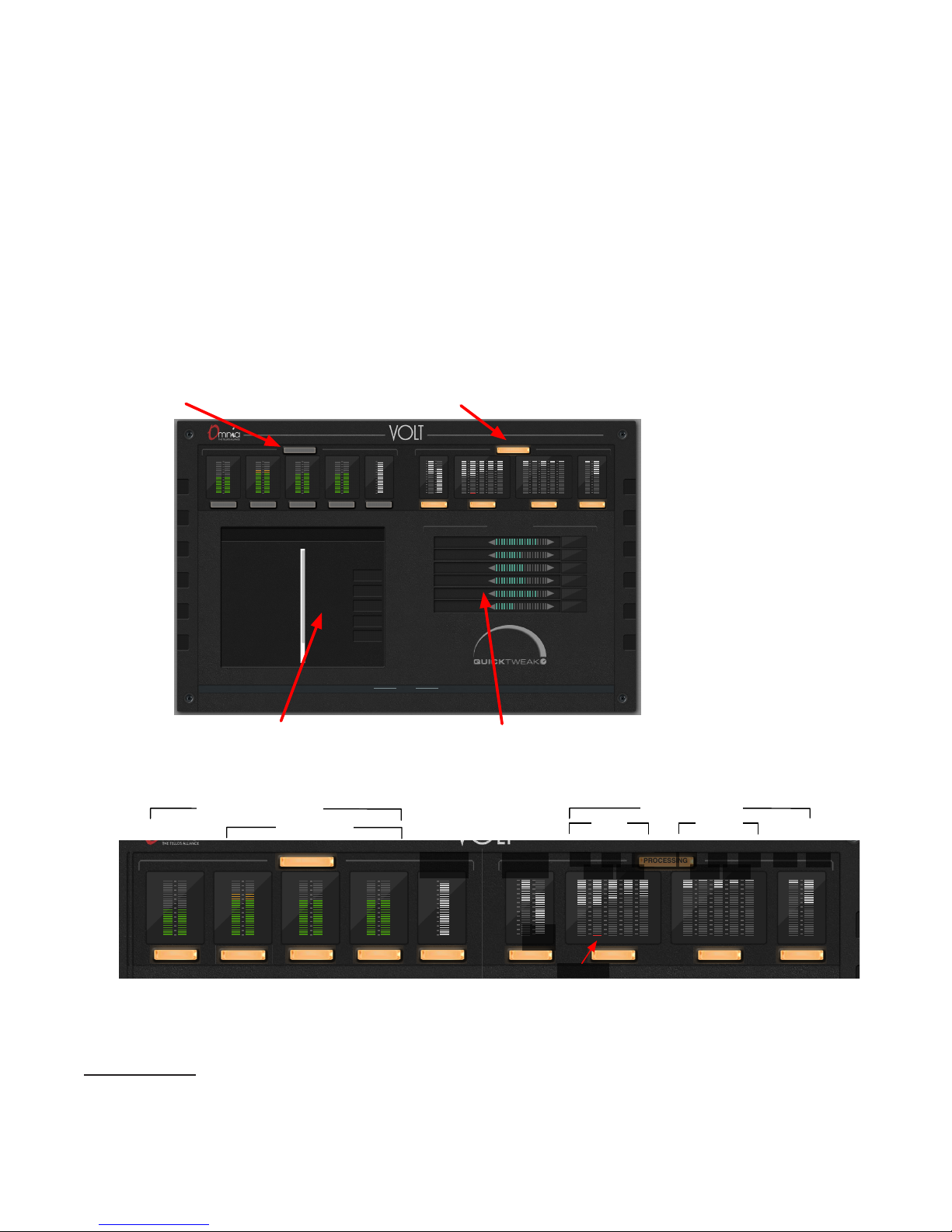
Omnia VOLT’s Remote Screen is designed to let you monitor every important behavior in one
place, and access every parameter with just a couple of intuitive clicks. The screen changes
slightly with different DSP|Core firmware, but the arrangement and control scheme stays the
same.
At the top of the Remote Screen are two rectangular buttons: I/O and Processing . Click on them
to manage presets and QuickTweak7 controls:
Immediately below those buttons is a row of meters:
This screenshot and description are based on FM Stereo VOLT. Meter functions can vary depending on the DSP|Core in use—obviously, there’s no need for a composite level meter on an
AM processor—but the meter arrangement will always be similar.
7 VOLT processing functions, including QuickTweak and SpaceFX, are covered in the next chapter.
Page 33
I/O PROCESSING
AES Output
Analog
AES
Livewire
Composite
FM Options
AES De-emphasis
Master
-12.00 dBFS
Right
0.00 dB
Sample Rate
On
Internal 48k
Function
menu
Selected function
Function controls
High-res meters
Parameter adjustmentDrop down menu
BROWSER-BASED REMOTE CONTROL
CHAPTER 5
| 25
The four pairs of meters on the left—showing mostly green bars—are stereo audio level meters.
They follow normal conventions for peak hold and color coding, and are calibrated 0 to -36
dBFS. These are levels at the processor, so they’re affected by individual level and channel
balance controls. The left-most stereo pair tracks the selected input. The other three show the
three Left/Right audio outputs, which are always active.
The other meters—showing mostly light gray bars—are not normal level meters.
♦ Composite shows the overall composite percentage, including any subcarrier applied at
the rear panel. The Composite meter is before any output level control, and is calibrated
0 – 100%
♦ The right-hand Initial meter shows how Space-FX is reacting to stereo material to maintain
a constant stereo width. It is calibrated 0 – 100%.
♦ The remaining light gray meters show Gain Reduction through the wideband AGC, the five
single-band AGC and Limiters, and the bass and wideband clipper. These are calibrated in
amount of reduction, from 0 dB at the top (no change in volume) to -24 dB at the bottom
(extreme leveling is being applied).
♦ The bottom segment of each AGC meter will turn red when gating is engaged.
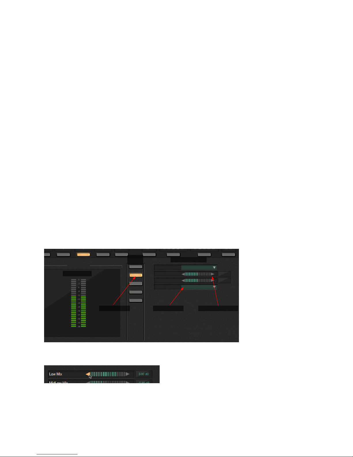
There’s a rectangular button below each set of meters. These activate a higher resolution version
of the meter set on the left side of the screen, and a menu of related functions down the middle
of the screen. Click on any one of these menu buttons to see controls for that function.
Function controls take two forms:
Parameter adjustments have triangles on either side of a horizontal meter. They let you increment a variable by clicking the left-facing triangle (reduce the value) or the right-facing one
(raise it). You can hold a triangle down for continuous incrementing. Range, scale, and units
when appropriate are displayed in the field to the right of the adjustment.
Page 34

BROWSER-BASED REMOTE CONTROL
CHAPTER 5
| 26
Drop down menus display text, and have a triangle on the right. Holding the triangle down
displays a menu of choices. Slide the pointer to the preferred choice, then release.
Most of the function names will be familiar to any broadcast engineer. Some of the processing
adjustments, however, are unique to VOLT. They’re described in the next chapter.
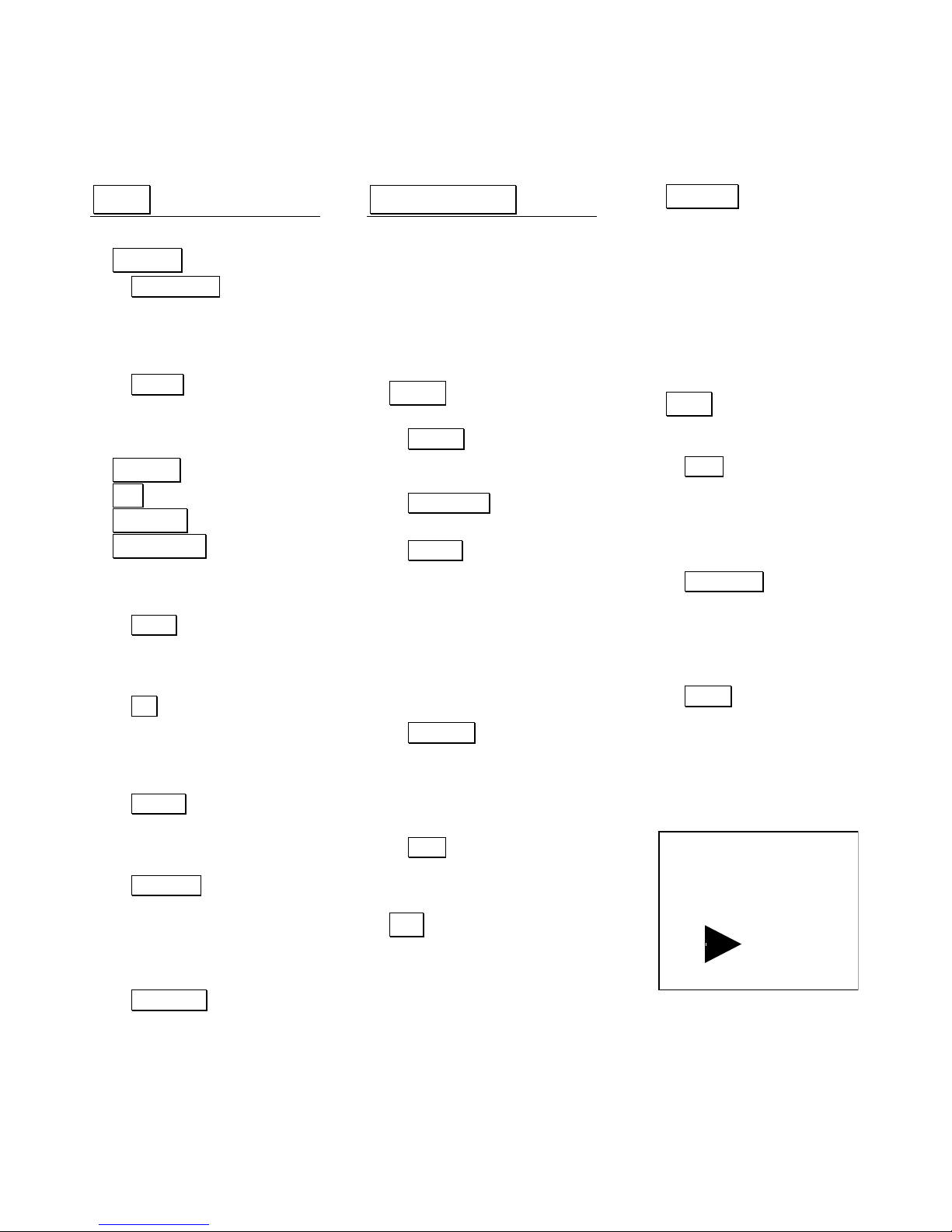
The next page is a reference map, so you can find specific adjustments quickly. Even without the
map, the layout should be intuitive. No adjustment is more than a couple of clicks away.
Page 35
I/O
I/Opresetlistandmanagement
INPUT
Configuration
Invert input polarity (options)
Input Source
Input Mode (stereo or
various mono options)
Failover
Fail Over Source
Fail Over Time
ANALOG
AES
LIVEWIRE
COMPOSITE
Eachofthesebuttonsbringsupa
differentlargeoutputmeteronthe
left.Menuchoicesarethesameforall:
Analog
Analog De-emphasis
Analog Out Level
Analog Out Right Level Trim
AES
AES De-emphasis
AES Out Level
AES Out Right Level Trim
Sample Rate
Livewire
Livewire De-emphasis
Livewire Out Level
Livewire Out Right Trim
Composite
Composite Out #1 Level
Composite Out #2 Level
Separation
Pilot Level
Pilot Phase
FMOptions
BS-412 Engage
BS-412 Threshold
Insert Return
Insert Send
Pre-emphasis
Test Tone
PROCESSING
Processingpresetlistand
management,plusQuickTweak:
Compression Depth
Density
Clipper Drive
Lows
Highs
Space-Efx
INITIAL
WidebandGRandSpace-EfxMeters
Pre-proc
HP Filter Freq
Phase Rotator
VoiceDetect
Voice Gain
WBAGC
Processing Active / Bypass
Drive
Attack
Release
Accel Release
Activity
Gate Thresh
RTZ Level
RTZ Speed
Enhancers
Processing Active / Bypass
Deep Bass
Phat Bass
Warmth
Space-Efx
Xover
LowMid XO frequency
MidHigh XO frequency
AGC
BringsupfiveindividualbandAGC
GainReductionmetersontheleft.5
Menuoptions,oneforeachband.
Eachbandhasseparatecontrolsfor
Drive
Attack
Release
Acel Release
Texture
Gate Thresh
RTZ Level
RTZ Speed
LIMITERS
BringsupfiveindividualbandLimiter
GRmetersontheleft.5Menuoptions,
oneforeachband.Eachbandhas
separatecontrolsfor
Drive
Attack
Release
Threshold
Hold Threshold
FINAL
BringsupBassandMainClipper
metersontheleft.
Mixer
Low Mix
MidLow Mix
Mid Mix
MidHigh Mix
High Mix
BassClipper
Bass Filtering
Bass Tight Clip on
Tight Threshold
Bass Girth Clip on
Girth Threshold
Clipper
Clipper Drive
Clipper Silk
Composite Clip Drive
Omnia.VOLT
Remote Control Map
FM Generator
Version 1.0
CORE
DSP
BROWSER-BASED REMOTE CONTROL
CHAPTER 5
| 27
Page 36

28
6
Omnia VOLT is not a plain-vanilla processor. We’ve taken our deep knowledge of broadcast
processing and DSP, refined some of the most popular Omnia algorithms, and developed brand
new ones.
The best way to learn how to adjust VOLT for your station and market is to work with it, using
this chapter as a guide.
This chapter is in three parts:
♦ Preset strategy and tuning, including QuickTweak. These are the philosophies we’ve
developed over years of working with stations, in every possible format and market size, all
around the world. So even if you already know how to tune a processor, you’ll probably get
something out of this section. It’s a quick read.
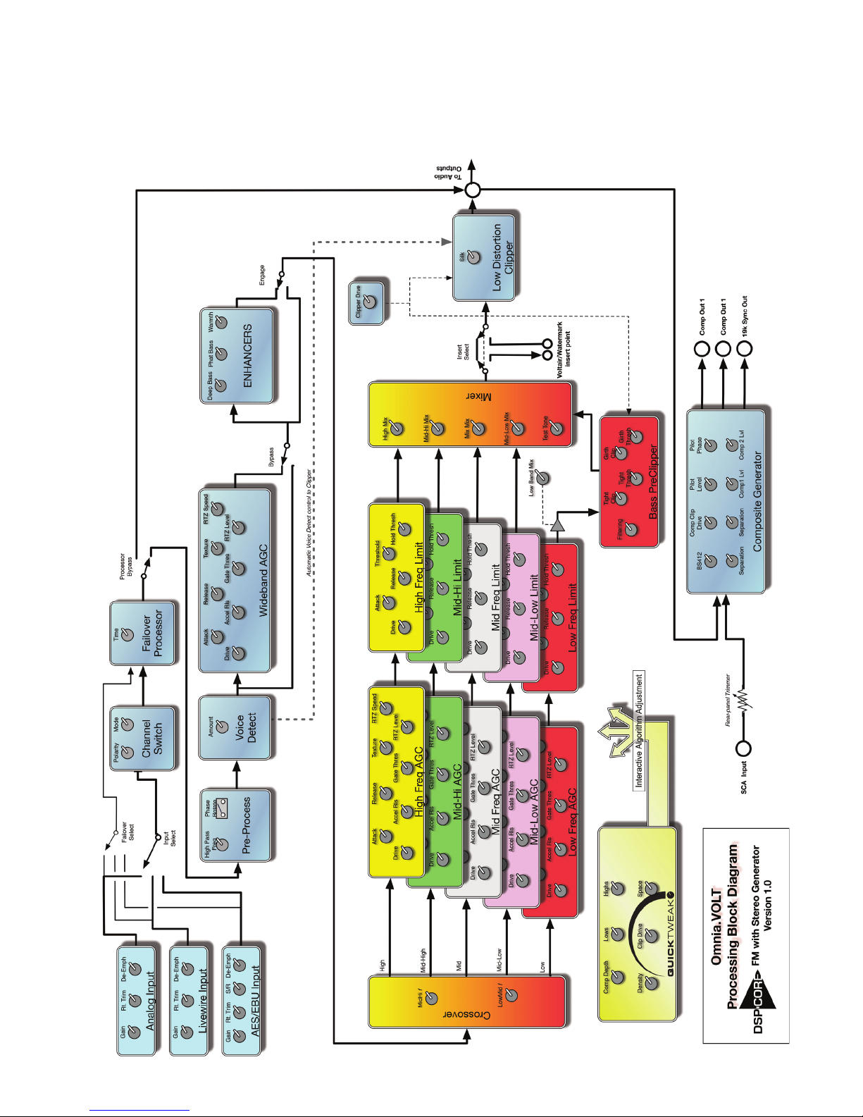
♦ VOLT processing block diagram. This will tell you what sequence VOLT uses to process
your signal, so you know which algorithms will be affected by the ones that come earlier.
♦ VOLT terminology. We’ve used standard audio processing language whenever possible.
But we had to invent new terms for some of the new algorithms. Turn to this section if
you’re not sure what a control is supposed to be doing.
VOLT Processing
Preset strategy and tuning
Before listening to presets, make sure input levels are correct. You can measure and adjust them from
the front panel or the Remote Control.
VOLT is designed to be used at -12 dBFS nominal; this is the level corresponding to “0 VU” on a
conventional analog meter. Adjust transmitter modulation and any subcarrier according to your
normal practice.
Don’t skip this step, and don’t try to over-drive VOLT’s input in hopes of “more density”. VOLT can
delivery all the density any station could ever want, while using proper input levels. Too much input
only adds distortion.
Page 37

VOLT PROCESSING
CHAPTER 6
| 29
Pick a preset.
Don’t get hung up on preset names. Our names might imply specific formats or effects, but
that’s mostly so our preset designers can keep track of them. Try a bunch: it takes just a moment
to load each preset, and loading doesn’t interrupt signal flow.
In fact, listening to all of the included factory presets is the best way to get a feel for what VOLT
can do. Decide which is closest to the sound you want, and use that as a starting point. Many
users like to play with VOLT in their shop before racking it: they feed typical program material,
try the controls, and audition all the presets. It’s a good idea.
Adjust the clipper.
Then, before you go any further, adjust the Clipper Drive as low as possible for the loudness you
need. This adjusts the primary tradeoff between loudness and distortion. Once it’s close, you
can start to use some of VOLT’s many ways to increase perceived loudness while actually lowering
distortion.
♦ Starting with the default setting for a preset, adjust Drive down in 0.5 dB steps until the
loudness drops just below what you want. Then bring it up slightly from there.
♦ If getting the desired loudness means you have to adjust Drive much higher than the pre-
set’s initial value, try a more aggressive preset.
Remember: Listeners might be attracted by loudness. But they’ll always be chased away by
distortion.
When used properly, Omnia VOLT can generate moment-to-moment loudness with plenty of
muscle, density, bass oomph and warmth, midrange intelligibility, treble sparkle and silk, stereo
consistency, and lots of other desirable characteristics.
But VOLT also provides Omnia’s famous clarity. That characteristic is appreciated by top programmers all over the world.
Think first. Then QuickTweak!
We’ve made it easy to optimize your processing for both quality and loudness. The first step—
before cranking it up—is to just listen to the chosen preset. Rather than “turn everything to 11”,
decide exactly what sonic characteristics might be lacking.
Page 38

VOLT PROCESSING
CHAPTER 6
| 30
Then reach for the QuickTweak knobs.
Four of the six QuickTweak controls—Compression Depth8, Density, Lows,
and Highs—can create the illusion of more loudness without overdriving
the clipper. These Interactive Algorithm Adjustments control multiple
parameters simultaneously, including some that aren’t otherwise adjustable. They’ve been carefully crafted using our extensive processing expe-
rience and input from leading broadcasters.
Adjust them one at a time, deliberately and methodically, concentrating first on the characteristic you think needs the most help. Make the smallest adjustment you can hear; this will depend
on your program material as well as the preset. Then listen critically before making another
adjustment.
If you think something is close, either write it down or save it as a preset. You might want to
come back to this setting, after tweaking the control more, or tweaking some other characteristic.
The other QuickTweak controls, Clipper Drive and Space-EFX, mirror the identically-named
settings in VOLT’s deep menus. We include them here for convenience: in a lot of cases, these
two knobs may be all you need along with the four main QuickTweaks. Save the result as a
preset, and you’re done.
Go deeper… if you think there’s a reason.
In many cases, QuickTweak will give you the sound you want.
With some formats and markets, you might want to get a bit deeper. VOLT has more than 140 routing
and processing settings. Feel free to explore all of them in your search for sonic perfection.
And don’t worry about making a mistake: if you save a custom-named preset before you start adjusting individual settings, you’ll always be able to come back to its baseline. For safety, factory presets
are write-protected and can’t be deleted.
There is no practical limit to the number of presets you can have. They can be loaded, renamed, or
deleted right from VOLT’s front panel or Remote Control. They can also be saved or retrieved on a
networked computer, shared with other VOLT users in your group, or externally stored as archives.
A few fine-tuning tips:
♦ The trade-off between quality and loudness is primarily determined by VOLT’s dynamic
sections. While each function alone can generate “dial presence,” each has different advantages and side effects.
♦ Excessive AGC or limiting can increase intermodulation distortion, making the audio
sound mushy or smeared. Adjusting the drive and time constants for each band separately
can control this.
8 QuickTweak is powerful. This “Depth” control does a lot more than similarly-named knobs on conventional
compressors. “Lows” and “Highs” are a lot more complex, internally, than the simple tone controls their names
suggest. And we’ve had to invent names for some other VOLT parameters as well, because of the new algorithms
they control. If you’re not sure what a knob does, check the glossary at the end of this chapter.
Page 39

VOLT PROCESSING
♦ Excessive AGC or limiting can also cause pumping or breathing, where very quiet passages
CHAPTER 6
| 31
are boosted too much. Gate and Hold thresholds can control this. Again, tune each band
separately.
♦ Don’t forget the Enhancers . They can add warmth, extra bass, or even a feeling of more
bass through smaller speakers: these low frequency effects can boost some programming
without driving the dynamics sections in to distortion. The Space-EFX enhancement can
help keep your stereo soundstage consistent and exciting across a variety of different
recordings.
♦ Take it in small doses. Plan to do a little adjusting at a time, perhaps in half-hour segments
with breaks between. Too much listening, at extreme settings, can fool you into thinking a
distorted or fatiguing sound is better than it really is.
Volt Processing Block Diagram
A lot of VOLT’s processing power depends on how each algorithm is fed by the ones that come
before it. The diagram on the next page explains this signal flow, and can also help you find
specific controls in the Remote Control.
Page 40
VOLT PROCESSING
CHAPTER 6
| 32
Page 41

VOLT PROCESSING
CHAPTER 6
| 33
VOLT Processing Terminology
Most of VOLT’s controls are labeled with standard studio or processing definitions, and should
be intuitive to any engineer. But a few names are our own invention… because they’re controlling algorithms of our own invention. Here’s a glossary of those terms:
QuickTweak
Density: Controls relative drive into the limiter bands, while ratios and time constants are
program-dependent.
Lows: Affects both the amount and shape of processing for the two bottom bands.
Highs: Amount and shape of processing for the two top bands.
Pre-process and Enhancers
Deep Bass: Adds psychoacoustic bump by enhancing just the very low frequencies, such as kick
drum fundamentals.
Phat Bass: Actually makes the speakers in small radios (and earbuds) sound bigger. Adds
harmonic overtones for frequencies those smaller transducers can’t carry, fooling the ear into
thinking the fundamentals are there. On larger speakers, the effect starts to disappear (because
the fundamentals are there in the first place). Be careful! Too much Phat Bass can cause excessive
gain reduction in the lower bands, and might cause muddiness on certain programming.
Warmth: Shelf boost at 150 Hz, compensating for some program material. Be careful! The Phat
Bass warning applies. Also, the resonant frequency of many automobile interiors lies in this range; too
much warmth may sound tubby in cars.
Space-EFX: Dynamically compensates for variations in width between one song (or verse) and
another.
Voice Detect: Constantly checks for mono program elements (including voice). When it hears
them, it lowers the main channel by the amount you specify in Voice Gain. This can prevent
excessive clipping because of L+R buildup.
Xover Lets you adjust the two critical crossover frequencies that affect warmth and intelligibility or brightness.
AGC [Automatic Gain Control]
Accelerated Release: Speeds up the AGC recovery time when there’s a big difference between
loud and soft program elements, to prevent “holes” in your dynamic profile.
Activity: Affects ratio, attack time, and release time interactively on wideband AGC. Makes
programming sound like its more tightly controlled.
Texture: Similar to Activity, but on the five separate-band AGCs. It adds a finer level of control.
Gate Threshold: When signal falls below this threshold, GR [Gain Reduction] is frozen at its
most recent level. This stops the AGC from boosting those soft but annoying sounds like talent
breathing or tape hiss. GR is released when signal exceeds the threshold.
Page 42

VOLT PROCESSING
CHAPTER 6
| 34
RTZ Level: [Return to Zero] Determines idling GR, for when the input is silent. This prevents
the GR from falling to zero, which would cause a sudden burst of loudness when the signal starts
again.
RTZ Speed: Determines how quickly GR will go from previous value to RTZ Level.
Limiter
Hold Threshold: Preserves dynamics when sudden peaks are followed by moderate decreases in
level, by temporarily stopping the GR from releasing. The result is a drastic reduction in intermodulation distortion as well as a more open sound, even though the audio is still quite dense.
This also works in conjunction with the AGC’s Gate.
Bass and Broadband Clippers
Bass Tight Clip: Hard clipper just on the bass notes, to keep them from modulating the main
clipper. Usually most effective on drums.
Bass Girth Clip: More like a musician’s effect; makes upper harmonics of bass notes bigger and
broader.
Clipper Silk: Adjusts the texture of the main clipper when handling significant mid- and upper
mid-range material such as lead guitar. Actually modifies our distortion-cancelling algorithm:
lower-numbered settings soften (or silken) the effects of clipping at the expense of a small
amount of perceived loudness.
Page 43

35
7
VOLT is solidly built, with rigorously tested hardware and software. Nonetheless, no electronic
equipment is immune from occasional problems. These pages will help you identify which ones
can be fixed quickly and locally, and which may require contacting us.
In an emergency, you can reach our Support Team anytime, by calling +1 (216) 622-0247.
VOLT includes factory diagnostics available on the Remote Control’s Conguration tab. When
contacting customer support, you may be instructed how to retrieve important information so it
can be read or emailed to us for analysis.
For billing questions or other non-emergency technical questions, email Support@TelosAlliance.
com or call +1 (216) 241-7225 between 9:00 AM - 5:00 PM USA Eastern Time, weekdays.
There’s full contact information at the end of this chapter, and at the end of this manual.
Features and operations of VOLT are determined largely by software. Telos strives to provide
the most stable and feature-rich software available. We encourage you to check for software
updates from time to time by visiting our website or by contacting us directly.
Troubleshooting and Updates
Contacting Us…
By Phone/Fax
You can reach our 24/7 Support Team in emergencies by calling +1(216) 622-0247. For billing
questions or other non-emergency technical questions, call +1 (216) 241-7225 between 9:00
AM to 5:00 PM USA Eastern Time, Monday through Friday.
By Email
Non-emergency technical support is available at [email protected].
By Web
The Telos Web site has a variety of information that may be useful for product selection and
support. The URL is TelosAlliance.com. See the Omnia section for VOLT news and updates.
Page 44

36
8
We are constantly working to improve our products. Specifications and features are subject
to change without notice. Audio quality is measured through VOLT’s entire chain but with
processing controls turned off.
Technical Specications
System
Frequency Response: User selection of flat, 50 µs, or 75 µs pre-emphasis curve within ± 0.50 dB,
30 Hz to 15 kHz.
System Distortion: Less than 0.01% THD, 20 Hz – 7.5 kHz (second harmonic distortion above
7.5 kHz is not audible in the FM system).
Signal-Noise Ratio: Audio >95 dB analog, >120 dB digital i/o.
System Latency: 16ms nominal, +- .5ms depending on I/O selections
Input / Output
Composite: Output impedance 75Ω, single-ended and floating over chassis ground. BNC con-
nectors with EMI suppression. Maximum cable 100’ / 30M RG-58U.
♦ Output level: separately adjustable for each of two outputs, 0V - 10V in 0.05V steps.
♦ Pilot Level: Adjustable from 4.0% to 12.0% in 0.1% steps and OFF.
¸ Pilot Stability: 19 kHz, ± 0.5 Hz.
¸ S/N: -85 dB typical, 75 µS de-emphasized across 15 kHz, at 100% modulation.
¸ Distortion: < 0.02% THD 20 Hz – 15 kHz, 75 µS de-emphasized @ 100%.
♦ Stereo Separation: > 65 dB, 30 Hz – 15 kHz.
¸ Linear Crosstalk: > -80 dB, main to sub or sub to main channel @ 100%.
¸ Non-linear Crosstalk: > -80 dB, main to sub or sub to main @ 100%.
¸ 38 kHz Suppression: > 70 dB @ 100%.
¸ 76 kHz Suppression: > 80 dB @ 100%.
¸ Pilot Protection: > -65 dB relative to 9% pilot injection, ± 1 kHz.
¸ 57 kHz (RDS/RBDS) Protection: > -50 dB.
Page 45

TECHNICAL SPECIFICATIONS
CHAPTER 8
| 37
Analog: Left and Right Stereo on EMI-suppressed XLR-3, balanced with “pin 2 hot”.
♦ Input: Electronic balanced, impedance 10kΩ, nominal +4 dBu, max +22 dBu.
♦ Output: impedance 20Ω for >600Ω load, +4 dBu nominal, +22 dBu peak.
♦ Converters: 24 bit, 128x oversampled with linear-phase anti-aliasing filter.
Digital: Stereo per AES/EBU standard, 24 bit resolution. Input locks to any rate 32 kHz – 108
kHz. Output locks to input, internal 48 kHz, or separate external AES/EBU “digital black”
reference 32 kHz – 96 kHz.
Livewire: Audio over IP and control per Livewire standard, on same RJ-45 used for Ethernet
control.
Remote Control
GPI: EMI suppressed DB-9 at logic levels, +5 V and ground supplied.
Ethernet: 10/100BaseTX Ethernet on EMI-suppressed RJ-45. TCP/IP control via HTML-5
internal web server, password protected. Manual addressing and port selection.
Electrical/Physical
Power: 100 - 250 VAC, 47-63 Hz. < 40 VA. Typical draw 12W RMS, maximum 15W RMS.
Internal supply with overvoltage and short circuit protection. Meets EN55022, EN55011 Level
B Conducted Emissions. EN61000-4-2, -3, -4, -5, -6 level 3 immunity compliant. Full international safety approval. CE marked.
EMI suppressed IEC male connector. Detachable 3-wire power cords supplied for US and European use.
Temperature: 32° to 122° F / 0° to 50° C for all operating voltage ranges.
Humidity: 0-95% RH, non-condensing.
Dimensions: 19” wide x 1.75” high x 16” deep (48.26cm x 13.335 cm x 40.64 cm) including
connectors. Unit requires one EIA rack space for mounting.
Shipping Weight: 12 lbs. / 5.5 kg
Page 46

38
9
Telos Alliance Limited Warranty
This Warranty covers “the Products,” which are defined as the various audio equipment, parts,
software and accessories manufactured, sold and/or distributed by or on behalf of TLS Corp.
and its affiliated companies, collectively doing business as The Telos Alliance (hereinafter
“Telos”).
With the exception of software-only items, the Products are warranted to be free from defects in
material and workmanship for a period of five (5) years from the date of receipt of such Product
by the end-user (such date of receipt the “Receipt Date”). Software-only items are warranted to
be free from defects in material and workmanship for a period of 90 days from the Receipt Date.
Telos will repair or replace (in its discretion) defective Products returned to Telos within the
warranty period, subject to the provisions and limitations set forth herein.
This warranty will be void if the Product: (i) has been subjected, directly or indirectly, to Acts of
God, including (without limitation) lightning strikes or resultant power surges; (ii) has been
improperly installed or misused, including (without limitation) the failure to use telephone
and power line surge protection devices; (iii) has been damaged by accident or neglect. As
with all sensitive electronic equipment, to help prevent damage and or loss of data, we strongly
recommend the use of an uninterruptible power supply (UPS) with all of our Products. Telos
products are to be used with registered protective interface devices which satisfy regulatory
requirements in their country of use.
5-Year Warranty
This Warranty is void if the associated equipment was purchased or otherwise obtained through
sales channels not authorized by Telos.
EXCEPT FOR THE ABOVE-STATED EXPRESS WARRANTY, TELOS MAKES NO WARRANTIES, EXPRESS OR IMPLIED (INCLUDING IMPLIED WARRANTIES OF MERCHANTABILITY AND FITNESS FOR A PARTICULAR PURPOSE).
In no event will Telos, its directors, officers, employees, agents, owners, consultants or advisors
(its “Affiliates”), or authorized dealers or their respective Affiliates, be liable for incidental or
consequential damages, or for loss, damage, or expense directly or indirectly arising from the
use of any Product or the inability to use any Product either separately or in combination with
other equipment or materials, or from any other cause.
Page 47

5-YEAR WARRANTY
CHAPTER 9
| 39
In order to invoke this Warranty, the Product must be registered via Telos’ website (found at:
http://telosalliance.com/legal/warranty) at time of receipt by end-user and notice of a warran-
ty claim must be received by Telos within the above stated warranty period and warranty coverage must be authorized by Telos. Contact may be made via email: [email protected]
or via telephone: (+1) 216-241-7225. If Telos authorizes the performance of warranty service,
the defective Product must be delivered to: Telos, 1241 Superior Avenue East, Cleveland, Ohio
44114 or other company repair center as may be specified by Telos at the time of claim.
Shipping Costs and Warranty Service:
If the date the customer’s notice of warranty claim is received by Telos (such date the “Warranty
Claim Notice Date”) is within the first 90 days following the Receipt Date, Telos will pay the
costs of shipping such warranted Product to and from the end user’s location, and the cost of
repair or replacement of such warranted Product.
If the Warranty Claim Notice Date occurs after the first 90 days following the Receipt Date and
before the end of the second (2nd) year, the customer will pay the freight to return the warranted Product to Telos. Telos will then, at its sole discretion, repair or replace the warranted
Product and return it to the end user at Telos’ expense.
If the Warranty Claim Notice Date occurs between the end of the second (2nd) year following
the Receipt Date and the completion of the fifth (5th) year, the customer will pay the costs of
shipping such warranted Product to and from the end user’s location. Telos will then, in its sole
discretion, repair or replace the warranted Product at Telos’ expense. Telos also reserves the
right, if it is not economically justifiable to repair the warranted Product, to offer a replacement
product of comparable performance and condition direct to the customer at a discounted price,
accepting the failed warranted Product as a trade-in.
The end user will in all cases be responsible for all duties and taxes associated with the shipment,
return and servicing of the warranted Product.
No distributor, dealer, or reseller of Telos products is authorized under any circumstances
to extend, expand or otherwise modify in any way the warranty provided by Telos, and any
attempt to do so is null and void and shall not be effective as against Telos or its Affiliates.
Out of warranty units returned to the factory for repair may be subject to a $500 evaluation fee,
which fee must be prepaid prior to shipping the unit to Telos. If no repairs are required, the $500
fee will be retained by Telos as an evaluation charge. If repairs are required, the $500 fee will be
applied to the total cost of the repair.
Page 48

1241 Superior Ave. • Cleveland, Ohio, 44114, USA • +1.216.241.7225 • TelosAlliance.com
© 2017 TLS Corp., All Rights Reserved. C17/15050 P/N: 1490-00177-001 --- USER MANUAL: OMNIA VOLT
 Loading...