

Page 1
+
Wireless Receiver Module V1.2
OMN-RCV3 (433MHz)
OMN-RCV386 (868MHz)
Reference & Installation Manual
Page 2

Page 3

TABLE OF CONTENTS
INTRODUCTION ........................................................................................3
Technical Specifications ...................................................................................3
System Features ...............................................................................................3
INSTALLATION .........................................................................................4
Location ............................................................................................................4
Connections and Mounting ...............................................................................4
PROGRAMMING .......................................................................................6
Programming Methods .....................................................................................6
How To Enter Module Programming Mode ......................................................7
Wireless Transmitter Programming ..................................................................8
Viewing the Signal Strength of Transmitters .....................................................9
Viewing the Actual Battery Life of Transmitters ..............................................10
Viewing the Previous Battery Life of Transmitters ..........................................11
Viewing Unknown Serial Numbers .................................................................11
System Reset .................................................................................................12
SUPERVISION OPTIONS ........................................................................13
Low Battery Supervision .................................................................................13
Check-In Supervision ......................................................................................13
Check-In Supervision Timer Settings .............................................................14
On-Board Module Tamper Supervision ..........................................................15
PGM Activation ...............................................................................................15
PGM Deactivation ...........................................................................................15
REMOTE CONTROLS .............................................................................16
Assigning Remote Controls to the Receiver Module ......................................17
Viewing and Deleting Remote Controls ..........................................................17
Assigning Remote Controls to User Access Codes ........................................18
Programming Remote Control Buttons ...........................................................18
Replacing the Remote Control Battery ...........................................................22
LIST OF SECTIONS ................................................................................23
Page 4

Page 5
1.0 INTRODUCTION
The Omnia Wireless Receiver Module (OMN-RCV3) allows you to add up to 16
Omnia Wireless detectors or door contacts, and up to 16 fully programmable remote
controls to the Digiplex or DigiplexNE system.
1.1 TECHNICAL SPECIFICATIONS
• Di-pole antenna
• Error Correction Algorithm
• Code-Hopping Technology
• Frequency: 433MHz or 868MHz
• Range (line of sight): PIRs & door contacts = 500ft (150m)
remote controls = 300ft (100m)
• Sensitivity: -120 dBm
• Current consumption: 50 mA
• Dimensions (no antenna): 15cm H x 16cm L x 3cm W
(6in H x 6.5in L x 1.1in W)
• Operating temperature: 0°C to 50°C (32°F to 122°F)
• Operating humidity: 85%
• PGM outputs: 1 relay (an additional PGM output is available)
• PGM output current: 5A
• Approvals:
433MHz
868MHz
*Specifications may change without prior notice.
1.2 SYSTEM FEATURES
• Auto-Panel Recognition
• Add 16 wireless motion detectors and/or door contacts to the Digiplex or
DigiplexNE system
• Add 16 remote controls to the Digiplex or DigiplexNE system
• Reflow design
• On-board tamper switch
Omnia 3
Page 6
• Full system supervision (check-in, low battery and tamper)
• Transmitter signal strength indicator
• Transmitter battery life display
2.0 INSTALLATION
The following sections will detail how to mount and connect the Omnia Wireless
Receiver Module (OMN-RCV3).
2.1 LOCATION
Mount the Wireless Receiver Module on a wall allowing at least 5cm (2in) around
the module to permit adequate ventilation and heat dissipation. Select a site that is
not susceptible to drastic temperature changes. Avoid installation near or in the path
of strong RF fields (i.e. neon lights, computers), on or near metal objects, circuit
breaker boxes, air conditioners, and heater ducts since they may cause interference
and reduce the module’s sensitivity. We recommend installing the module in a
centralized location on the main floor. Avoid installing the module in the basement.
Refer to the Digiplex or DigiplexNE Reference & Installation Manual for maximum
allowable distances between the control panel and the Wireless Receiver Module.
2.2 CONNECTIONS AND MOUNTING
Firmly screw the antenna into the connector marked ANT on the Receiver Module
(refer to Figure 2.1 on page 5). Using a drill or screwdriver, punch out the four
mounting holes on the back of the plastic case. Align the six holes of the printed
circuit board with the six pins on the back plastic mounting case and snap into place.
If placed correctly, the antenna will lean directly over the groove in the mounting
case.
Do not cut, bend, or alter the antennas. Avoid mounting the Receiver
Module near or on metal as this may affect its sensitivity .
The Receiver Module is connected to the control panel's communication network in
a star or daisy chain configuration. The communication network provides power and
two-way communication between the control panel and all the modules connected to
it. Refer to Figure 2.1 on page 5 for instructions on connecting the Wireless Receiver
Module to the control panel.
4 Reference & Installation Manual
Page 7
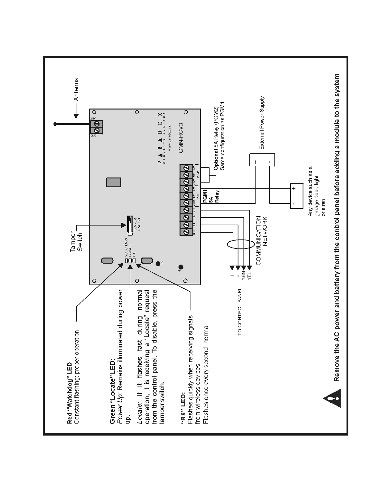
Figure 2.1: Connecting the Receiver Module to the Control Panel
Omnia 5
Page 8

3.0 PROGRAMMING
To successfully install an Omnia wireless system to your Digiplex or DigiplexNE
system, ensure that the following steps are completed:
1. Install the Omnia Receiver. Connect the Omnia Receiver to the Digiplex or
DigiplexNE control panel and power up.
2. Assign the remote controls if necessary.
3. Assign the transmitters (door contacts and motion detectors), and program their
zones.
4. Install the transmitters. Insert the batteries, and close the transmitter cover.
5. Wait for the control panel to be in “ready” mode. The status light on the keypad
will be green when the control panel is ready.
6. In order to ensure proper synchronization between the transmitters and receiver,
open and close the transmitters’ covers and zones.
3.1 PROGRAMMING METHODS
Programming of the OMN-RCV3 is accomplished using a variety of methods.
3.1.1 FEATURE SELECT PROGRAMMING (USING A KEYPAD)
Sections are programmed through the control panel’s Module Programming
Mode using the Feature Select Method, where each number from 1 to 8
corresponds to a specific feature or option. Set these options by turning the
number corresponding to the feature ON or OFF. The option is considered ON
when the number appears within the brackets on the LCD keypad or when the
number is illuminated on an LED Keypad. Press the number button again to
remove the digit, thereby disabling (turning OFF) the option. Press the buttons
as many times as you need to select the desired options and then press
[
ENTER] to save.
3.1.2 WINLOAD
With the WinLoad Security System Management Software, the control panels,
modules and keypads can be programmed remotely through a modem or onsite at 19,200 baud or 38,400 baud (DGP-NE96 only) with a 306 Adapter. For
details refer to the Digiplex or DigiplexNE Reference & Installation Manual.
6 Reference & Installation Manual
Page 9
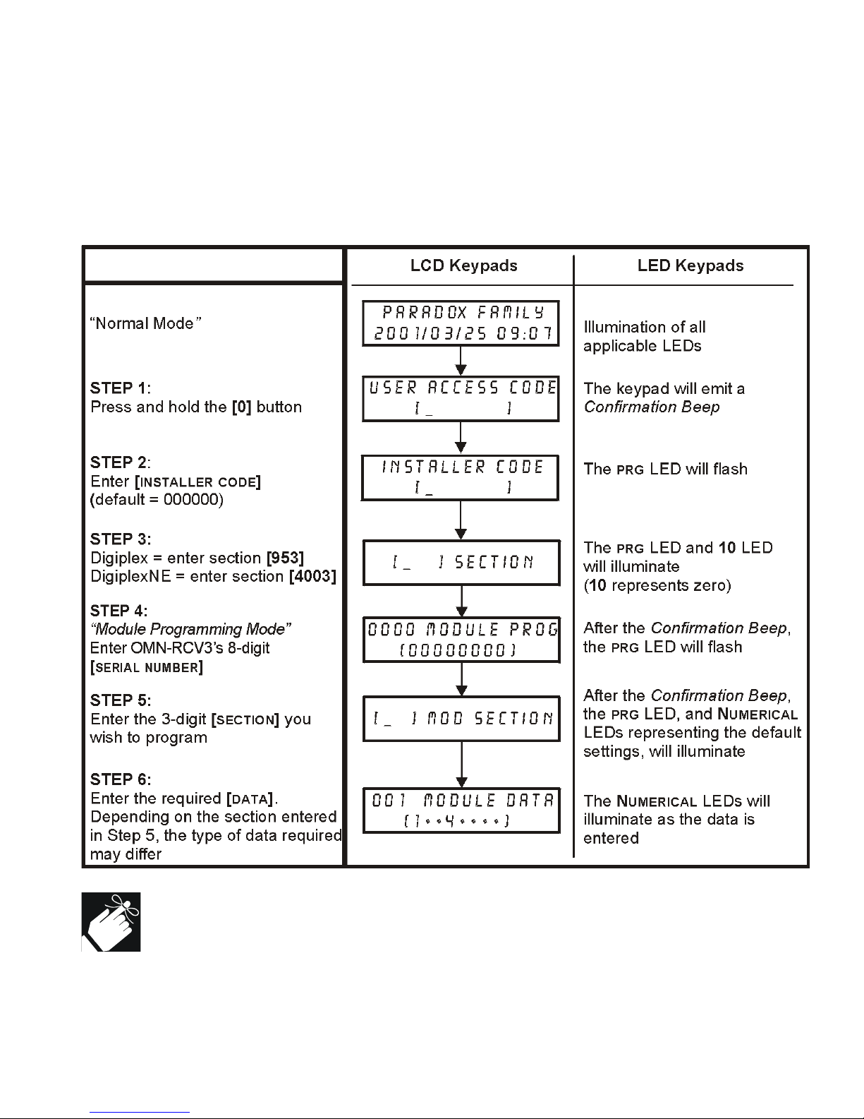
3.2 HOW TO ENTER MODULE PROGRAMMING MODE
All programming can be done through Module Programming Mode from any keypad
connected to the Digiplex or DigiplexNE system. Refer to Figure 3.3 for instructions
on how to enter Module Programming Mode.
Figure 3.3: Entering Module Programming Mode
Thesectionsreferredtoinstep5andthedatareferredtoinstep6inFigure
3.3 on page 7 are explored in the following sections of the manual.
Omnia 7
Page 10
3.3 WIRELESS TRANSMITTER PROGRAMMING
The programming of the wireless transmitters (detectors and door contacts) is
accomplished in three steps:
1. Assigning the detectors and door contacts to the Wireless Receiver Module.
2. Assigning the detectors and door contacts from the Wireless Receiver Module to
zones in the control panel.
3. Programming the zone parameters in the Digiplex or DigiplexNE control panel.
The assigned serial numbers and inputs will be needed when programming
the zones in the control panel. Therefore, insert the data in the
Programming Guide while assigning the detectors and door contacts.
In Omnia, sections [101] to [116], [601] to [616], [701] to [716], and [801] to [816]
are interrelated. For example, when assigning a detector or door contact to
expansion input 001 in the Receiver Module:
1. The serial number and input number will be assigned in section [101].
2. Its signal strength can be viewed in section [601].
3. Its actual battery life can be viewed in section [701].
4. Its previous battery life can be viewed in section [801].
3.3.4 ASSIGNING DETECTORS AND DOOR CONTACTS TO THE MODULE
SECTIONS [101] TO [116]
Up to 16 wireless transmitters (detectors and door contacts) can be assigned
to each Receiver Module. Sections [101] to [116] represent expansion inputs
001 to 016 respectively. For example, section [101] is assigned to expansion
input 001, section [102] is assigned to expansion input 002, etc..
How to assign detectors & door contacts to a module.
In step 5 in Figure 3.3 on page 7:
1. Enter the desired [
2. Enter the 6-digit serial number of the detector or door contact.
SECTION NUMBER] (101 to 116).
The serial number is located on the inside of the transmitter, or you
can use the Viewing Unknown Serial Numbers feature (section 3.7 on
page 1 1) to determine the transmitter’s serial number.
8 Reference & Installation Manual
Page 11
When one section is programmed, the keypad will automatically
switch to the next section.
3.3.5 DELETING THE TRANSMITTERS ASSIGNED TO THE RECEIVER
SECTIONS [101] TO [116]
The transmitters assigned in sections [101] to [116] can also be deleted in the
same sections.
How to delete the assigned transmitters.
In step 5 in Figure 3.3 on page 7:
1. Enter the desired [
SECTION NUMBER] (101 to 116).
2. Enter 6 zeros (000000) in place of the 6-digit serial number.
3.3.6 ASSIGNING THE TRANSMITTERS TO ZONES IN THE CONTROL PANEL
The detectors and door contacts must be assigned to zones in the control
panel. The allocated zones must then be programmed. For more information
on assigning and programming zones, refer to the Digiplex or DigiplexNE
Reference & Installation Manual.
3.4 VIEWING THE SIGNAL STRENGTH OF TRANSMITTERS
SECTIONS [601] TO [616]
Once the detectors and/or door contacts have been installed and assigned to the
Receiver Module, the actual signal strength of each device can be verified in
sections [601] to [616]. Each section represents the signal strength viewer for a
specific device. For example, section [601] is the viewer for the device in section
[101] and section [616] is the viewer for the device in section [116].
Omnia 9
Page 12
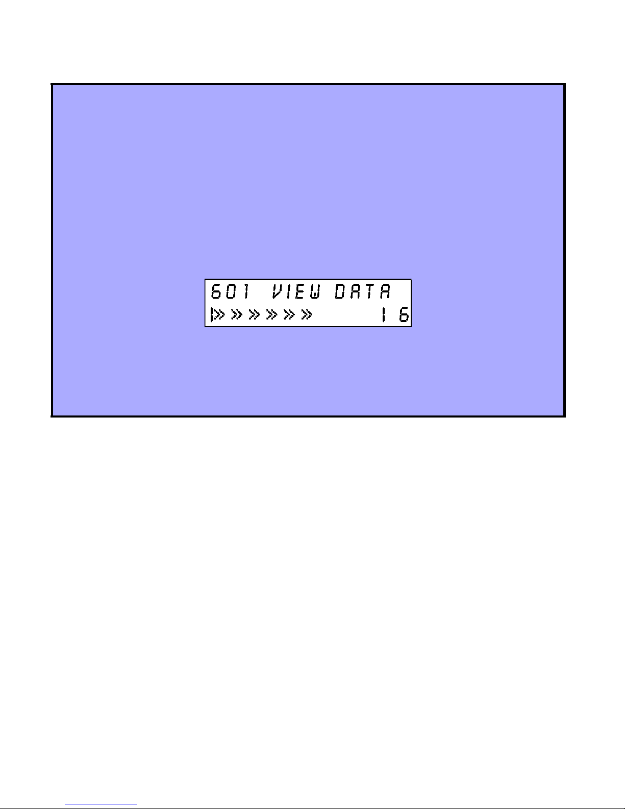
How to view the signal strength of a wireless transmitter.
In Step 5 in Figure 3.3 on page 7:
1. Enter the desired [
SECTION NUMBER] (601 to 616).
2. Press the transmitter’s tamper switch, or open the zone assigned to the
transmitter.
On an LCD keypad: The signal strength is represented by one to ten arrows
that will appear on the LCD screen below the words “View Data”. The
numeric reading will appear to the right of the arrows. Three characters or
less is a very weak signal and the device should be moved. Any reading
above four characters is acceptable.
On an LED keypad: The signal strength is represented by the illumination of
the numerical LEDs from LED 1 to LED 10. A reading from LED 1 to LED 3 is
a very weak signal and the device should be moved. An average reading
above LED 4 is acceptable.
3.5 VIEWING THE ACTUAL BATTERY LIFE OF TRANSMITTERS
SECTIONS [701] TO [716]
These sections allow you to view the amount of time, in weeks, a battery has been in
a specific transmitter. The counter will begin one week after you insert the batteries
into the transmitter. For example, if you install the batteries in one of the
transmitters, you will only be able to view the actual battery life after one week. Each
section represents the actual battery life reading of a specific transmitter. For
example, section [701] is the actual battery life reading for the transmitter assigned
in section [101], and section [716] is the reading for the transmitter assigned in
section [116].
10 Reference & Installation Manual
Page 13

How to view the actual battery life of the transmitters.
In Step 5 in Figure 3.3 on page 7:
1. Enter the desired [
SECTION NUMBER] (701 to 716).
2. The number value (001 to 255) in the chosen section represents the number
of weeks the batteries have been inside the transmitter. For example, if the
value is 006, the batteries have been in the transmitter for 6 weeks.
3.6 VIEWING THE PREVIOUS BATTERY LIFE OF TRANSMITTERS
SECTIONS [801] TO [816]
These sections allow you to view the amount of time, in weeks, the previous
batteries in a specific transmitter lasted. The value will be saved one week after the
new batteries are installed. For example, if you replace the batteries in one of the
transmitters, you will only be able to view the previous battery life after one week.
Each section represents the previous battery life reading of a specific transmitter.
For example, section [801] is the previous battery life reading for the transmitter
assigned in section [101], and section [816] is the reading for the transmitter
assigned in section [116].
How to view the previous battery life of the transmitters.
In Step 5 in Figure 3.3 on page 7:
1. Enter the desired [
SECTION NUMBER] (801 to 816).
2. The number value (001 to 255) in the chosen section represents the number
of weeks a transmitter’s previous batteries lasted. For example, if the value
is 006, the previous batteries lasted 6 weeks.
3.7 VIEWING UNKNOWN SERIAL NUMBERS
SECTION [030]
The serial number of a detector or door contact can be viewed in this section.
Omnia 11
Page 14
How to view unknown serial numbers.
From Step 5 in Figure 3.3 on page 7:
1. Enter section [030].
2. Press and hold the tamper switch on the detector or door contact.
On an LCD keypad, the device's serial number appears on the LCD screen
under the words “View Data”.
On an LED keypad, the first number of the device's serial number will
illuminate (10 = zero). Press the [!!!!] button to view each subsequent
number. When you press the [""""] button on the last number of the serial
number, the control panel will exit the section.
3.8 SYSTEM RESET
Performing a system reset will erase all the sections in the Wireless Receiver
Module's programming and set the following section to default settings:
Section # Default Settings
[001] Options1to8=OFF
How to reset the system.
1. Press and hold the [0] button.
2. Enter the [
INSTALLER CODE] (default=000000).
3. Enter the appropriate [section number]:
Digiplex = [951]
DigiplexNE = [4001]
4. Enter the Omnia Wireless Receiver [
SERIAL NUMBER].
12 Reference & Installation Manual
Page 15

4.0 SUPERVISION OPTIONS
The Omnia Wireless Receiver Module offers a variety of supervision options that
allows the module to monitor the status of the module, detectors, and door contacts.
4.1 LOW BATTERY SUPERVISION
SECTION [001] : OPTION [1]
Option [1] enables the Low Battery Supervision feature. When a detector or door
contact’s battery voltage drops below a recommended level (refer to the
transmitter’s Instructions), its red LED will flash and it will transmit a signal to the
Wireless Receiver Module indicating that the voltage is low. If this option is enabled,
the Receiver Module will transmit the signal to the control panel which will generate
a trouble and can transmit a report code to the monitoring station (refer to the
Digiplex or DigiplexNE Reference & Installation Manual).
How to enable low battery supervision.
In step 5 in Figure 3.3 on page 7:
1. Enter section [001].
2. Enable or disable option [1].
Option [1] OFF = Low Battery Supervision disabled (default)
Option [1] ON = Low Battery Supervision enabled
4.2 CHECK-IN SUPERVISION
SECTION [001] : OPTION [2]
Option [2] enables the Check-in Supervision feature. The Wireless Receiver Module
waits for each of its assigned detectors and/or door contacts to send a status signal
within a specified time period (as programmed in section 4.3 on page 14) to confirm
their presence and functionality. If a device has not sent a signal within that time
period, the Wireless Receiver Module will transmit a supervision loss signal to the
control panel. The control panel can then generate a trouble, an alarm and/or can
transmit a report code to the monitoring station. For details refer to the Digiplex or
DigiplexNE Reference & Installation Manual.
Omnia 13
Page 16
How to enable check-in supervision.
In step 5 in Figure 3.3 on page 7:
1. Enter section [001].
2. Enable or disable option [2].
Option [2] OFF = Check-In Supervision disabled (default)
Option [2] ON = Check-In Supervision enabled
4.3 CHECK-IN SUPERVISION TIMER SETTINGS
SECTION [001] : OPTIONS [3] AND [4]
Options [3] and [4] define the time period that must elapse before the Omnia
transmitters send a status signal to the Wireless Receiver Module. For example, if
the timer is set to 12 minutes (option [3]=on ; option [4]=off), the transmitters will
send a status signal every 12 minutes to the Receiver Module. For high-security
installations select the lowest check-in time (6 minutes). Selecting the longest
check-in time (12 hours) will conserve battery power.
How to set the check-in supervision timer.
In step 5 in Figure 3.3 on page 7:
1. Enter section [001].
2. Enable or disable options [3] & [4].
Option [3] OFF = hours (default)
Option [3] ON = minutes
Option [4] OFF = 12 (default)
Option [4] ON =6
Ensure that the assigned detectors and door contacts are set to the same
Check-In time period as the Receiver Module. For example, if the Receiver
Module is set to 12 minutes, the detectors and door contacts must also be
set to 12 minutes.
14 Reference & Installation Manual
Page 17

4.4 ON-BOARD MODULE TAMPER SUPERVISION
SECTION [001] : OPTION [5]
Option [5] enables the On-Board Tamper Supervision feature. If this option is
enabled and the Receiver Module's cover is removed, the on-board tamper switch
will be triggered. When this occurs, the Wireless Receiver Module will transmit a
tamper signal to the control panel. The control panel can then generate a trouble, an
alarm and/or can transmit a report code to the monitoring station. For details refer to
the Digiplex or DigiplexNE Reference & Installation Manual.
How to enable the on-board module tamper supervision.
In step 5 in Figure 3.3 on page 7:
1. Enter section [001].
2. Enable or disable option [5].
Option [5] OFF = On-Board Module Tamper Supervision disabled
(default)
Option [5] ON = On-Board Module Tamper Supervision enabled
4.5 PGM ACTIVATION
The Omnia Wireless Receiver Module comes equipped with one on-board 5A PGM
relay output (programmable output). A second 5A PGM output is available as an
option. PGM1 and PGM2 are always enabled and are activated only through the
Omnia Remote Control (OMN-RCT1). Remote control button 1 (C) controls PGM1,
and button 2 (D) controls PGM2 (refer to Figure 5.1 on page 20 for button locations).
Press the appropriate remote control button to activate the corresponding PGM. If
the PGM deactivation mode is set at “Manually” (refer to section 4.6), the button
used to activate the PGM will also be used to deactivate the PGM.
4.6 PGM DEACTIVATION
SECTION [001] : OPTIONS [6] AND [7]
Once a PGM has been activated (refer to section 4.5), options [6] and [7] determine
how the respective PGM will deactivate. If the option is OFF, the activated PGM will
automatically deactivate after 2 seconds. If the option is ON, the activated PGM can
only be deactivated by pressing the appropriate button on the Omnia Remote
Control (refer to section 4.5).
Omnia 15
Page 18
How to set the PGM deactivation mode.
In step 5 in Figure 3.3 on page 7:
1. Enter section [001].
2. Enable or disable options [6] and [7].
Option [6] OFF = PGM1: 2 second timer (default)
Option [6] ON = PGM1: Manually
Option [7] OFF = PGM2: 2 second timer (default)
Option [7] ON = PGM2: Manually
5.0 REMOTE CONTROLS
The Omnia Wireless Receiver Module accepts up to 16 fully programmable remote
controls. Programming the remote controls is accomplished in three steps:
1. Remote controls must be assigned to the Wireless Receiver Module.
2. The remote controls from the Wireless Receiver Module must be assigned to
User Access Codes.
3. The buttons on the remote controls must be programmed.
In Omnia, sections [201] to [216], [040], [041], [301] to [316], and [401] to [416] are
all interrelated. For example, when assigning a remote control to the Receiver
Module:
1. The remote control is assigned using the Automatic Learning method in sections
[201] to [216].
2. The number of remote controls assigned to the Receiver will automatically appear
in sections [040] and [041].
3. The remote control is assigned to User Access Codes in sections [301] to [316].
4. The remote controls’ buttons are programmed in sections [401] to [416].
The remote control will transmit a signal for only 1 second when a button is
pressed. This is done to prolong the remote control’s battery life.
16 Reference & Installation Manual
Page 19
5.1 ASSIGNING REMOTE CONTROLS TO THE RECEIVER MODULE
SECTIONS [201] TO [216]
Up to 16 remote controls can be assigned to each Omnia Wireless Receiver Module
without occupying any zones in the Digiplex or DigiplexNE control panel. Remote
controls are assigned to the module using the Automatic Learning method.
How to assign remote controls to the Receiver Module.
In step 5 in Figure 3.3 on page 7:
1. Enter the desired [
SECTION NUMBER] (201 to 216).
2. Press any button on the remote control twice, or until the confirmation beep
sounds (“Beep-Beep-Beep-Beep-Beep”).
If a rejection beep is heard (“Beeeeeeeeeeeep”), or if you are having
trouble assigning the remote control, the environment may be too noisy.
Therefore, we recommend that you assign the remote controls before
instal lin g the detectors and door contacts.
5.2 VIEWING AND DELETING REMOTE CONTROLS
SECTIONS [040] AND [041]
The number of remote controls assigned to the Receiver Module can be viewed in
sections [040] and [041]. This feature is especially useful when you wish to verify if
the remote controls have been successfully assigned. The remote controls assigned
to sections [201] to [208] appear in section [040], and those assigned to sections
[209] to [216] appear in section [041].
In section [040] remote controls assigned to sections [201] to [208] appear
as 1 through 8. For example, the remote control assigned to section [201]
would appear as “1” in section [040].
Remote controls can also be deleted through sections [040] and [041] by pressing
the button corresponding to the remote control. For example, to delete the remote
control assigned to section [201], press the [1] button in section [040] until the “1” no
longer appears on the screen, then press [
ENTER].
Omnia 17
Page 20
5.3 ASSIGNING REMOTE CONTROLS TO USER ACCESS CODES
SECTIONS [301] TO [316]
Each remote control must be assigned to a User Access Code. All User Access
Codes are given a User Number from 001 to 096 (Digiplex), or from 001 to 255
(DigiplexNE). Enter the desired User Number in a section from [301] to [316] that
represent the remote control assigned to sections [201] to [216] (refer to section 5.1
on page 17). For example, the User Number designated in section [301] would be
assigned to the remote control assigned in section [201].
With the DigiplexNE, User Access Codes 256 to 999 cannot be assigned to
a remote control.
How to assign a remote control to a user access code.
In step 5 in Figure 3.3 on page 7:
1. Enter the desired [
SECTION NUMBER] (301 to 316).
2. Enter the User Number to be assigned to the remote control:
Digiplex = (001 to 096)
DigiplexNE = (001 to 255)
5.4 PROGRAMMING REMOTE CONTROL BUTTONS
SECTIONS [401] TO [416]
Each remote control can be programmed to send a signal to the control panel to
perform up to 8 different actions (refer to Table 5.1 on page 21). Each digit in
sections [401] to [416] represents a button or combination of buttons (refer to Figure
5.2 on page 20). When a user arms or disarms using the remote control, the control
panel will arm or disarm all the areas assigned to the User Access Code. For
example, you arm with a remote control whose User Access Code is assigned to
areas 1 and 3, the control panel will attempt to arm areas 1 and 3.
Sections [401] to [416] represent the remote controls assigned to sections [201] to
[216] (refer to section 5.1 on page 17). For example, the buttons for the remote
control assigned in section [201] will be programmed in section [401].
18 Reference & Installation Manual
Page 21

For installations using LCD Keypads:
How to program the remote control buttons using an LCD keypad.
In step 5 in Figure 3.3 on page 7:
1. Enter a [
SECTION NUMBER] (401 to 416).
2. Place the cursor under the digit of the button or button combination you want
to program using the arrow buttons (see Figure 5.2 on page 20). Enter the
hexadecimal value (0 to F) of the desired option from Table 5.1 on page 21.
3. Repeat step 2 for each button or button combination of the remote control.
4. Press [
ENTER] once the remote control is programmed. The LCD screen will
automatically switch to the next section for the next remote control.
Note: To delete the hexadecimal values (button programming) in a particular
section (401-416), press the [0] button once for every value.
For installations using LED Keypads:
How to program the remote control buttons using an LED keypad.
In step 5 in Figure 3.3 on page 7:
1. Enter a [
SECTION NUMBER] (401 to 416).
2. Enter the hexadecimal value (0 to F) of the desired option from Table 5.1 on
page 21. After every second digit programmed, the keypad will emit a beep
tone:
First digit: enter the choice for Button A
Second digit: enter the choice for Button B
(BEEP-BEEP-BEEP)
Third digit: enter the choice for Button C
Fourth digit: enter the choice for Button D
(BEEP-BEEP-BEEP)
Fifthdigit: enterthechoiceforButtonsA+B
Sixthdigit: enterthechoiceforButtonsC+D
(BEEP-BEEP-BEEP)
Seventh digit: enter the choice for Buttons A+C
Eighth digit: enter the choice for Buttons B+D
(BEEP-BEEP-BEEP-BEEP-BEEP) Confirmation Beep
3. Press [ENTER].
Note: To delete the hexadecimal values (button programming) in a particular
section (401-416), press the [0] button once for every value.
Omnia 19
Page 22
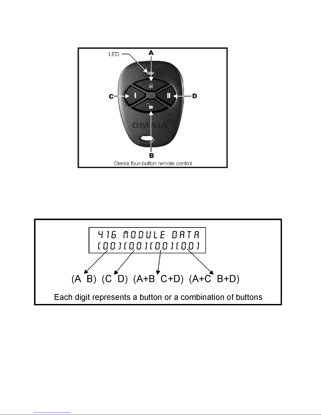
Figure 5.1: Remote Control Button Identification
Figure 5.2: Button Programming on LCD Screen
20 Reference & Installation Manual
Page 23
Table 5.1: Button Functions
[0] = Button Disabled [8] = Panic 2
[1] = Regular Arm [9] = Panic 3
[2] = Stay Arm [A] = Smoke reset
[3] = Instant Arm [B] = Utility Key 1 (see warning below)
[4] = Force Arm [C] = Utility Key 2 (see warning below)
[5] = Disarm [D] = Utility Key 3 (see warning below)
[6] = Stay/Instant Disarm [E] = Utility Key 4 (see warning below)
[7] = Panic 1 [F] = Utility Key 5 (see warning below)
For Digiplex systems, refer to the PGM table (First Digit: 8) in the Digiplex
Programming Guide. For DigiplexNE systems, refer to the PGM table
(Event Group: 048) in the DigiplexNE Programming Guide.
In Digiplex (DGP-48) versions prior to 2.12, button choices [1] to [9] will
ONLY function with the System Master Code (Code 001).
These keypad buttons represent the hexadecimal values from A to F
[STAY] = A [ARM]= C [BYP]= E
[FORCE] = B [DISARM]= D [MEM]= F
For installations using the LED keypads, the hexadecimal values will
illuminate the following LEDs
A=[
B=[
STAY]LED C=[A1]LED E=[BYP]LED
FORCE]LED D=[A4]LED F=[MEM]LED
Omnia 21
Page 24
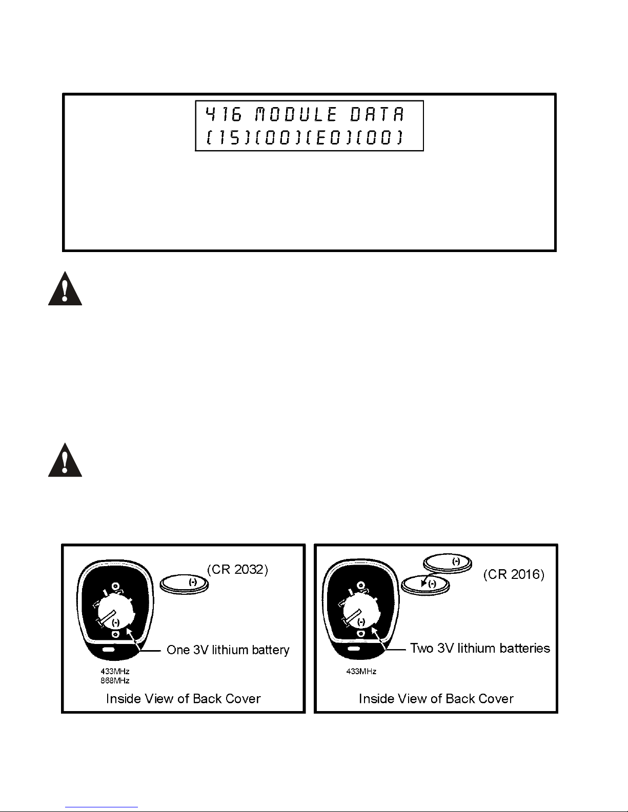
Figure 5.3: Example of Programmed Buttons on LCD screen
Example: Button A is programmed to Regular Arm, button B is
programmed to Disarm, and the combination of buttons A+B is
programmed to activate the PGM(s) according to the appropriate
PGM Table (Utility Key 4). The other buttons and their combinations
are not programmed.
With the LED keypads, you can verify the programming in each section by
returningtothedesiredsectionandpressingthe[!!!!] button. The
numerical LEDs and the LEDs representing the hexadecimal values will
illuminate one at a time as you press the button.
5.5 REPLACING THE REMOTE CONTROL BATTERY
The Omnia 433MHz remote control requires either one or two lithium batteries and
the Omnia 868MHz remote control requires one 3V lithium battery. The number of
batteries that is required is stated on the inside of the back cover.
Replace the batteries with the same or equivalent type as detailed in Figure
5.4. Danger of explosion exists if the lithium battery is replaced incorrectly.
Dispose of the used batteries according to the manufacturer’s instructions.
Figure 5.4: RC Batteries
22 Reference & Installation Manual
Page 25
How to replace the remote control battery or batteries.
1. Remove the two screws from the back of the remote control and remove the
back cover.
2. Remove the old battery or batteries from inside the remote control.
3. Replace with appropriate battery or batteries (refer to Figure 5.4 on page 22)
ensuring proper polarity. The positive of the battery or batteries is inserted
face down.
4. Set the back cover in place, and fasten it with the two screws.
6.0 LIST OF SECTIONS
Section Description
[001] Option [1]: Low battery supervision
Option [2]: Check-in supervision
Option [3]: Check-in supervision base time
Option [4]: Check-in supervision time value
Option [5]: On-board module tamper supervision
Option [6]: PGM1 deactivation mode
Option [7]: PGM2 deactivation mode
[030] View unknown serial numbers
[040] and [041] - View the number of remote controls assigned to the
receiver
- Delete the remote controls
[101] to [116] - Assign detectors and door contacts to the receiver
- Delete the detectors and door contacts
[201] to [216] Assign a remote control to the receiver
[301] to [316] Assign the remote controls to user access codes
[401] to [416] Program the remote control buttons
[601] to [616] View the detector and door contact signal strengths
[701] to [716] View the actual battery life of the transmitters
[801] to [816] View the previous battery life of the transmitters
Omnia 23
Page 26

Warranty
The Seller warrants its products to be free from defects in materials and
workmanship under normal use for a period of one year (unless otherwise
indicated). Except as specifically stated herein, all express or implied warranties
whatsoever, statutory or otherwise, including without limitation, any implied warranty
of merchantability and fitness for a particular purpose, are expressly excluded.
Because Seller does not install or connect the products and because the products
may be used in conjunction with products not manufactured by Seller, Seller cannot
guarantee the performance of the security system. Seller obligation and liability
under this warranty is expressly limited to repairing or replacing, at Seller's option,
any product not meeting the specifications. In no event shall the Seller be liable to
the buyer or any other person for any loss or damages whether direct or indirect or
consequential or incidental, including without limitation, any damages for lost profits,
stolen goods, or claims by any other party caused by defective goods or otherwise
arising from the improper, incorrect or otherwise faulty installation or use of the
merchandise sold.
Digiplex, DigiplexNE and Omnia are trademarks of Paradox Security Systems.
© 2002 Paradox Security Systems.
24 Reference & Installation Manual
Page 27

Page 28

PRINTED IN CANADA 05/2002
OMNRCV3D-EI02
 Loading...