

Page 1

OMNIA.7AM
USER’S MANUAL
p/n: 1490-00151-001
For part numbers: 2001-00455, 2001-00461, 2001-00460,
2001-00427 Omnia.7AM Software Version 3.15.70 | May 2016
Page 2

Notices and Cautions
CAUTION:
The installation and service instructions in this manual are for use by qualified personnel only. To avoid electric
shock, do not perform any servicing other than that contained in the operating instructions unless you are qualified
to do so. Refer all servicing to qualified personnel.
This instrument has an autoranging line voltage input. Ensure the power voltage is within the specified range of
100-240v. The ~ symbol, if used, indicates an alternating current supply.
This symbol, wherever it appears, alerts you to the presence of uninsulated,
dangerous voltage inside the enclosure – voltage which may be sufficient to
constitute a risk of shock.
This symbol, wherever it appears, alerts you to important operating and
maintenance instructions. Read the manual.
CAUTION: DOUBLE POLE/NEUTRAL FUSING
The instrument power supply incorporates an internal fuse. Hazardous voltages may still be present on some of the
primary parts even when the fuse has blown. If fuse replacement is required, replace fuse only with same type and
value for continued protection against fire.
WARNING:
The product’s power cord is the primary disconnect device. The socket outlet should be located near the device and
easily accessible. The unit should not be located such that access to the power cord is impaired. If the unit is incorporated into an equipment rack, an easily accessible safety disconnect device should be included in the rack design.
To reduce the risk of electrical shock, do not expose this product to rain or moisture. This unit is for indoor use only.
This equipment requires the free flow of air for adequate cooling. Do not block the ventilation openings in the top
and sides of the unit. Failure to allow proper ventilation could damage the unit or create a fire hazard. Do not place
the units on a carpet, bedding, or other materials that could interfere with any panel ventilation openings.
If the equipment is used in a manner not specified by the manufacturer, the protection provided by the equipment
may be impaired.
Page 3

WARNUNG:
Die Installations-und Serviceanleitung in diesem Handbuch ist für die Benutzung durch qualifiziertes Fachpersonal. Um Stromschläge zu vermeiden führen Sie keine andere Wartung durch als in dieser Betriebsanleitung aufgeführt, es sei denn Sie sind dafür qualifiziert. Überlassen Sie alle Reparaturarbeiten qualifiziertem Fachpersonal.
Dieses Gerät hat eine automatische Bereichseinstellung der Netzspannung.
Stellen sie sicher, dass die verwendete Netzspannung im Bereich von 100-240V liegt.
Das Symbol ~, falls verwendet, bezeichnet eine Wechselstromversorgung.
Dieses Symbol, wo immer es auftaucht, macht Sie auf nicht isolierte,
gefährliche elektrische Spannung (ausreichend um einen Stromschlag
hervorzurufen) innerhalb des Gehäuses aufmerksam. Spannungen.
Dieses Symbol, wo immer es auftaucht, weist Sie auf wichtige Bedienungs-und
Wartungsanleitung hin. Lesen Sie die Bedienungsanleitung.
ACHTUNG: ZWEIPOLIGE ABSICHERUNG / NULLEITER ABSICHERUNG
Das Netzteil des Gerätes hat eine interne Sicherung eingebaut. Auch wenn die Sicherung durchgebrannt ist,
können auf einigen primären Bauteilen noch gefährliche Spannungen vorhanden sein. Wenn ein Austausch der
Sicherung erforderlich ist, ersetzen Sie die Sicherung nur mit gleicher Art und Wert für den kontinuierlichen
Schutz gegen Feuer.
WARNUNG:
Das Gerätenetzkabel ist die Haupttrennvorrichtung. Die Steckdose sollte sich in der Nähe des Gerätes befinden und
leicht zugänglich sein. Das Gerät sollte nicht so angeordnet sein, dass der Zugang zum Netzkabel beeinträchtigt ist.
Wird das Gerät in ein Rack eingebaut, sollte eine leicht zugängliche Sicherheitstrennvorrichtung in den Rack-Aufbau mit einbezogen werden.
Um die Gefahr von Stromschlägen zu verringern, darf dieses Produkt nicht Regen oder Feuchtigkeit ausgesetzt
werden. Dieses Gerät ist nur für die Benützung im Innenbereich. Dieses Gerät erfordert freie Luftzirkulation für
eine ausreichende Kühlung. Blockieren sie nicht die Lüftungsschlitze auf der Geräteoberseite und den Seiten des
Gerätes. Unzureichende Belüftung kann das Gerät beschädigen oder Brandgefahr verursachen. Platzieren Sie das
Gerät nicht auf einem Teppich, Poster oder andere Materialien welche die Lüftungsöffnungen beeinträchtigen
könnten.
Wird das Gerät anders als in der, vom Hersteller angegebenen Weise verwendet, kann der, durch das Gerät
gegebene Schutz beeinträchtigt werden.
Page 4

USA CLASS A COMPUTING DEVICE INFORMATION TO USER. WARNING:
This equipment generates, uses, and can radiate radio-frequency energy. If it is not installed and used as directed by
this manual, it may cause interference to radio communication. This equipment complies with the limits for a class
a computing device, as specified by fcc rules, part 15, subpart j, which are designed to provide reasonable protection against such interference when this type of equipment is operated in a commercial environment. Operation
of this equipment in a residential area is likely to cause interference. If it does, the user will be required to eliminate
the interference at the user’s expense. Note: objectionable interference to tv or radio reception can occur if other
devices are connected to this device without the use of shielded interconnect cables. Fcc rules require the use of
shielded cables.
CANADA WARNING:
“This digital apparatus does not exceed the class a limits for radio noise emissions set out in the radio interference
regulations of the Canadian department of communications.”
“Le présent appareil numérique n’émet pas de bruits radioélectriques dépassant les limites applicables aux appareils numériques (de class a) prescrites dans le règlement sur le brouillage radioélectrique édicté par le ministère
des communications du Canada.”
CE CONFORMANCE INFORMATION:
This device complies with the requirements of the EEC council directives:
♦ 93/68/EEC (CE MARKING)
♦ 73/23/EEC (SAFETY – LOW VOLTAGE DIRECTIVE)
♦ 89/336/EEC (ELECTROMAGNETIC COMPATIBILITY)
Conformity is declared to those standards: EN50081-1, EN50082-1.
Page 5

OMNIA.7AM MANUAL
© 2014-2016 TLS Corp. Published by Omnia Audio/TLS Corp. All rights reserved.
TRADEMARKS
Omnia Audio, the Omnia logo and Omnia.7AM are trademarks of TLS Corp. All other trademarks are the property
of their respective holders.
NOTICE
All versions, claims of compatibility, trademarks, etc. of hardware and software products not made by Omnia
Audio which are mentioned in this manual or accompanying material are informational only. Omnia makes no
endorsement of any particular product for any purpose, nor claims any responsibility for operation or accuracy. We
reserve the right to make improvements or changes in the products described in this manual which may affect the
product specifications, or to revise the manual without notice.
WARRANTY
This product is covered by a five year limited warranty, the full text of which is included in this manual.
UPDATES
The operation of Omnia.7AM is determined largely by software. We routinely release new versions to add features
and fix bugs. Check the Omnia Audio web site for the latest. We encourage you to sign-up for the email notification
service offered on the site.
FEEDBACK
We welcome feedback on any aspect of Omnia.7AM, or this manual. In the past, many good ideas from users have
made their way into software revisions or new products. Please contact us with your comments.
SERVICE
You must contact Omnia before returning any equipment for factory service. We will need your unit’s serial
number, located on the back of the unit. Omnia will issue a return authorization number, which must be written
on the exterior of your shipping container. Please do not include cables or accessories unless specifically requested
by the Technical Support Engineer. Be sure to adequately insure your shipment for its replacement value. Packages
without proper authorization may be refused. US customers, please contact Omnia Technical Support at
+1-216-622-0247. All other customers should contact local representative to make arrangements for service.
Page 6

WE SUPPORT YOU...
BY PHONE / FAX:
♦ You may reach our 24/7 Support team anytime around the clock by calling +1-216-622-0247.
♦ For billing questions or other non-emergency technical questions, call +1-216-241-7225 between 9:30
am to 6:00 PM, USA Eastern time, Monday through Friday.
♦ Our Fax number is +1-216-241-4103.
BY E-MAIL:
♦ Technical support is available at [email protected].
♦ All other questions, please email [email protected].
VIA WORLD WIDE WEB:
The Omnia Audio web site has a variety of information which may be useful for product selection and support.
The url is www.Telosalliance.com.
REGISTER YOUR PRODUCT
Did you know that all Telos Alliance products come with a 5-Year Warranty? Take a moment to activate your
coverage online at http://telosalliance.com/product-registration/ .
OMNIA AUDIO
1241 Superior Avenue E.
Cleveland, OH., 44114 USA
+1-216-241-7225 (phone)
+1-216-241-4103 (fax)
+1-216-622-0247 (24/7 technical support)
Page 7

VII | Table of Contents
Intro A Letter from our CEO, Frank Foti VIII
Intro Getting the Most from this Manual IX
1 The Omnia.7 Story 1
2 Quick Startup Guide 3
3 General Processing Advice 7
4 Home Screen & User Interface 9
5 NfRemote Client Software 11
6 Reading the Meters 23
7 Home Menu 25
8 Input > Source Audio Menu 27
9 Input > Undo Menu 29
10 AM Menu 36
11 Display & Meter Options 60
12 Studio Processing Menu 72
13 HD Processing Menu 73
14 Streaming Menu 74
15 Monitor Output Menu 86
16 System Menu 95
17 Getting the Sound You Want 120
18 Frequently Asked Questions (FAQ) 123
19 Specications & Warranty 126
Page 8

VIII | A Letter from our CEO, Frank Foti
War of the Waves
Dear Valued Customer,
It’s with great pride and a tip of the hat to an incredible team that I congratulate you on your new Telos Alliance
product. Everything we do here at the radio division of the Telos Alliance is with one end goal in mind: To help
broadcasters declare victory in extremely competitive environments. By purchasing this product from us, in
essence, you have declared war on your competition.
After all, the majority of Telos Alliance employees were broadcasters themselves once, and the products we’ve
developed over the years have been designed as solutions to specific issues faced on the front lines of our industry.
We’re right there in the trenches with you and have the weapons you need in your arsenal.
Telos Systems is a catalyst to out-of-this-world sound, with the most powerful and popular broadcast telephone
systems in the industry; IP/ISDN codecs and transceivers; plus processing/encoding for streaming audio. We built
an industry on the back of these amazing telephony systems, and they are still going strong.
While we at the Telos Alliance never forget our roots, we are also blazing trails in terms of new technologies like
stream-encoding and AoIP, so that all types of broadcasters can excel in this ever-evolving digital world.
Omnia Audio not only lets you stand out on the dial with your unique signature sound via legendary audio
processors, audio codecs, and microphone processing, it lets you give your listeners a better streaming experience
across devices with innovative stream encoding/processing software and hardware.
Axia Audio is a driving force behind the AES67 AoIP standard, and its networked AoIP radio consoles, audio
interfaces, networked intercom, and software products continue to move AoIP adoption forward and help
broadcasters streamline operations with cohesive, smart, and feature-rich AoIP ecosystems.
Last, but certainly not least, 25-Seven has traditionally been known for its audio delays, but its Voltair watermark
monitor/processor has made a name for itself more recently as the disruptive product that helped broadcasters
take back their ratings and harness the true power of their listening audiences.
You work so hard on your programming day-in and day-out, it deserves technology that will optimize sound and
performance at every point in the airchain and online. Armed with Telos products, you have what you need to set
your competition squarely in your crosshairs.
With that, I’ll leave you to prep your armaments. I hope that you will enjoy your Telos Alliance products for many
years to come!
Sincerely,
Frank Foti
CEO, The Telos Alliance
Page 9

IX | Getting the Most from this Manual
Getting the Most from this Manual
Let’s be honest about a few things right up front:
♦ Omnia.7 offers a lot of power and flexibility, characteristics that inherently bring a degree of complexity
along for the ride.
♦ Its menu and control architecture is logical, but also broad and deep, so we’ve organized the chapters and
their contents in a manner that duplicates the menu structure of the front panel from the big picture (the
Home Screen) down to every individual control.
♦ This is not a short manual.
♦ Your time is valuable and limited.
While we’d love for everyone to read this enthralling literary masterpiece cover-to-cover and fully understand all of
what Omnia.7 can do, that’s just not practical for the majority of users.
Most of you would like to rack it up, plug it in, find a suitable preset for your taste and market, maybe tweak it up
a bit, and then try to eat lunch before the really important stuff lands on your desk. Like the virus-plagued laptop
from that sales guy (again). Or the wireless mic that the intern backed over with the promotions van (again). Or
the urinal that won’t stop running. You know, the real reasons you got into broadcasting.
With that in mind, here’s what we suggest:
♦ When you’re done here, go to Chapter 2, the Quick Startup Guide. This is bare bones stuff including
physical I/O, routing the audio within Omnia.7, setting levels, and picking a preset.
♦ Read Chapter 18, the FAQ section. Most users have the same or similar questions. We’ve attempted to
answer those here.
♦ Read Chapter 3, General Processing Advice, especially if you don’t consider yourself to be a processing
expert. It’s a short chapter but has non-technical, non-product-specific tips that will serve as a good
foundation as you adjust your sound. This is also good reading for your Program Director, General
Manager, or anyone else who may have a say in the overall sound of the station. We encourage you to
share it with them.
♦ Read Chapters 4 and 6 - they’ll get you familiar with using the controls and reading the meters.
♦ Glance through Chapter 16, the System menu, or just poke around the System menu on the front panel
just to get an idea of what’s there. These tend to be high-level, global, set-and-forget items.
Page 10

THE OMNIA.7 STORY
CHAPTER 1
| 1
1
The Omnia.7 Story
How Omnia.7 Came to Be
As of the this writing, Omnia.9 by Leif Claesson - Omnia.7’s “big brother” - has been on the air re-defining the
sound of FM radio around the world for nearly five years now.
During that time, we’ve learned that broadcasters really do appreciate the “clean and clear” philosophy that defines
Omnia.9 but not everyone has the need (or the budget) for a top-of-the-line audio processor that packs in the
amount of features and flexibility Omnia.9 does. This is especially true in mid-sized and smaller radio markets.
We felt it was time to build a processor that brought the most important sonic characteristics of Omnia.9 - including “Undo” (with its de-clipper and multiband expander) and and its psychoacoustic distortion-masking clipper
- but in a simplified, more purpose-built processor, and without a few of the premium features offered in Omnia.9.
The result was Omnia.7 for FM.
AM processing was first added to the Omnia.9 as an option. That option is exactly what is provided here in a
dedicated, top-performing AM processor; the Omnia.7 AM!
Processing for AM, HD, Streaming, and Studio
Omnia.7 offers completely separate processing cores for AM, (optional) HD and Streaming, and features a
dedicated low-latency studio core for talent monitoring.
Each processing core contains and Input AGC, a 4-band fully parametric equalizer, multiband noise reduction,
multiband stereo enhancement, an Input AGC, two wideband AGC’s (selectable), and up to 5 bands of multiband
AGC and peak limiting.
Omnia.7 also introduces the concept of “Basic”, “Intermediate”, and “Advanced” controls, making it friendlier and
less intimidating to use for those who are not audio processing experts while still providing access to all controls for
expert users who want to really dig in and fine tune their sound.
The Omnia.7 Toolbox
Omnia.9 introduced the unique concept of a diagnostic “toolbox” and provided a built-in digital oscilloscope, an
RTA, and an FFT spectrum analyzer that can monitor dozens of different points within each of its processing cores.
Omnia.7 retains all of those same tools including a pink noise generator and a powerful parametric equalizer so
that you can calibrate your reference speakers, giving you an accurate monitoring point from which to adjust your
processing.
These features allow you to “see what you are hearing” and make informed, intelligent adjustments to your audio
that were heretofore difficult if not impossible to make.
Page 11

THE OMNIA.7 STORY
There’s Still Lots of Power
Despite its mid-level positioning in the Omnia product lineup, Omnia.7 still provides more control and power than
you may be accustomed to.
Giving you full access to all of its controls is like giving you the keys to an exotic sports car. If you know what you’re
doing, you’re in for quite a ride! And if you don’t, well, let’s just say there are lots of ways to get yourself loose in the
corners and end up in the weeds. But for all of its capabilities, Omnia.7 is not difficult to set up and use, especially in
“Basic” mode.
We’ve given you some great presets based on those found in Omnia.9, created and tuned by people who know the
product best, that will either satisfy your on-air processing goals right out of the box or will get you close enough
to your desired sound so that you can make some tweaks to suit your individual needs and tastes for your format in
your market.
That said, we highly recommend that you set aside some time up front to understand the various design philosophies and controls that make Omnia.7 so unique, versatile, and powerful. The time you spend now will pay off
exponentially on-air, make your program director smile and sleep better at night, and keep the rest of the stations
in the market wondering what kind of freaky magic you’re up to.
If you send us cash, expensive gifts, or can make the Cleveland Browns win a Superbowl, we promise not to tell
them.
CHAPTER 1
| 2
Page 12

QUICK STARTUP GUIDE
CHAPTER 2
| 3
2
We know that you’re probably in a hurry to get your new Omnia.7 installed and on the air. If you have technical
expertise and previous knowledge of audio processor fundamentals, this Quick-Start Setup Guide will get you up
and running as quickly as possible.
It is important to remember that because some features in Omnia.7 are optional, not everything referenced in this
guide or in the full product manual may be available in your particular unit. Therefore, some screenshots may differ
slightly in appearance.
While Omnia.7 is a svelte 2RU product, we still suggest having an assistant on hand when racking it up to help
balance the unit during installation. We don’t want to see your new processor accidentally land on the floor nor do
we want to live with the guilt of knowing you spent time in the chiropractor’s office because of something we built.
(If you’re going to end up there, make it because of something more fun than racking up gear). We also strongly
recommend using all 4 rack screws for the best support. Finally, although the unit is fan cooled, leaving an empty
rack space directly above and below the unit is still good practice for both Omnia.7 and the equipment directly
above and below it.
Quick Start Setup Guide
Physical Installation and Initial Conguration
Connect AC power to both of the internal power supplies. Don’t plug it in while standing in a bathtub (the things
our lawyers make us say). There is no power switch.
It is always possible for a supply to fail and so having redundant supplies does help protect you against losing power
altogether in that event, but in reality, it is far more likely that the unit will lose power because of an interruption to
the circuit feeding the unit. Therefore, good engineering practice dictates that each supply should be fed from a
different source. At minimum, we recommend that both sources should be a good quality UPS with adequate surge
protection. In an ideal world (where everyone gets along and you got to build the plant of your dreams from scratch
with an unlimited budget) each would be fed from a completely different circuit for maximum redundancy.
Next, connect the audio inputs as appropriate for your installation. Omnia.7 accepts balanced professional
line-level analog audio via its Left and Right Analog Inputs and AES/EBU digital audio on standard XLR connectors
via its AES inputs.
Page 13

QUICK STARTUP GUIDE
Note:
An important word about AES reference and sample rates!
Omnia.7 oers several clock sync/reference options:
The main AES XLR inputs can accept audio with a reference of either 44.1kHz (for HD Radio) or
48kHz (for DAB). To set the sample rate, navigate to the System > System Conguration > Sample
Rate menu and set the unit’s sample rate to match that of the incoming signal and the Sync
Reference control to “Main Input.”
If the incoming AES audio has a dierent sample rate between 32kHz and 96kHz, it can be up- or
down-sampled to either 44.1 or 48kHz by setting the Sync Reference control to “Reference Input.”
The unit’s sample rate must be selected in the Sample Rate menu.
Finally, a dedicated external reference input is provided on the rear panel via a BNC connector
should it be necessary to sync to a clock that is not present on the incoming AES audio (such as an
HD exporter at the transmitter site). Set the Sync Reference to “Reference Input”. The unit’s sample
rate must be selected in the Sample Rate menu. A BNC-to-XLR cable or adapter (Pin 2 hot, Pin 3
shield) may be used for short runs without concern. For longer runs, a transformer should be used
as needed.
CHAPTER 2
| 4
Front Panel Controls and Navigation
Unlike other products in the Omnia family, Omnia.7 uses a “joystick” type of rotary encoder for menu navigation
and control adjustment. “Rocking” the control left, right, up or down facilitates navigation through the various
menus. It may be helpful to think of these as being like the 4 “arrow” keys on a PC keyboard. Turning the knob
clockwise or counterclockwise adjusts individual controls.
For more information, see Chapter 4 starting on Page 9. We strongly suggest and recommend using the free
NfRemote control PC software after the initial configuration. Full details can be found in Chapter 5 starting on
Page 11 of this manual.
The factory default password is “1234”. Navigate to the “Password” field then move the joystick to the right to
bring up the on-screen keyboard. When the keyboard is displayed, turning the control clockwise or counterclockwise moves the cursor around the screen while rocking it to the right enters the highlighted value. Once the
password is entered, highlight and enter “OK”. Next, highlight and enter “Unlock” to unlock the unit.
The unit will always lock itself when the display times out and goes dark. The length of time before this happens is
adjustable in the System > System Config > Power menu.
Setting the Network Parameters
The System > System Config > IP Configuration menu allows you to choose whether Omnia.7 receives its IP
address from a DHCP server (the default setting) or is manually assigned a static address.
♦ The Use DHCP button allows your local router to assign an IP address to the unit.
♦ If Use DCHP is not selected, the fields for entering IP Address, Subnet Mask, Gateway, and DNS informa-
tion become active.
♦ Selecting Apply puts any changes you have made to these parameters into effect after a few seconds.
For full information about getting the NfRemote app up & running, see Chapter 5 starting on Page 11.
Page 14

QUICK STARTUP GUIDE
Select the Input Audio Source
Navigate to the System > I/O Options > Input menu and select the proper source (analog or digital) for the
primary and/or backup inputs.
Adjust Input Audio
Note that the Omnia.7 AM audio is blended to mono after the input stage so the processing is always fed in mono.
From the Home menu, navigate to the System > I/O Options > Source Adjustment menu. Use the Input Gain slider
to set the input levels. When driving the input with typical program material at normal operating levels, adjust the
input gain while watching the Input meters in the Processing display window so that average levels keep the meters
in the green. If the meters flash red, the input is being overdriven and levels to the Omnia.7 must be reduced. It is
fine for the peak indicators to read up near 0 but should not go over 0 often.
If necessary, it is also possible to invert the polarity of either or both channels with the Invert control. The Channels
control allows several different channel configuration options. If running with stereo input audio, the Balance
control can adjust the static left/right channel balance offset before the L+R mono blend.
Congure Output Routing
Connect the audio outputs as appropriate for your installation. Omnia.7 supports balanced professional line-level
analog audio via its Left and Right Analog Outputs and AES/EBU digital output on standard XLR connectors via
the AES output.
CHAPTER 2
| 5
The 4 BNC connectors are not used in the AM version of the Omnia.7.
Navigate to the System > I/O Options > Main Outputs menu and select the appropriate output source to feed
the transmitter in your particular installation. Typically this would be or Analog Out: “AM TX Output” when
using the analog XLR output to feed your transmitter or Digital: “AM Digital Output” when using the AES/EBU
digital output to feed your transmitter Note that the level controls in this menu are grayed-out when selecting the
transmitter outputs. This is normal. The output levels will be adjusted in the AM Options menu. Other options
(such as HD), if selected here, will un-gray these level controls.
Adjust AM Diversity Delay (If equipped with HD option)
The AM diversity delay can be set by going to the System > I/O Options > Diversity Delay menu.
Page 15

QUICK STARTUP GUIDE
Choose a Preset
Return to the Home Menu, then navigate to the AM > Processing menu. Select Load Preset to choose one of the
factory presets. We suggest you audition all of the factory presets to get a feel for each of them.
Note:
Omnia.7 contains a relay-bypass feature that allows unprocessed audio to pass directly through the
unit to prevent complete loss of audio (dead air) any time the software is not active. This includes
when the unit loses power, is in the start-up process, or must re-initialize its software after applying
certain user-initiated conguration changes.
Normally this is not an issue. However, in certain situations - for example, if you have a CD player
connected to the analog inputs and an amplier or speakers connected to the analog outputs - this
means the input and output will be directly connected with no attenuation whatsoever, resulting
in fried speakers (or eardrums) or an eviction notice following complaints from irritable neighbors.
When engaged, the bypass relays hard wire the analog inputs to the analog outputs, and the AES
digital inputs to the AES digital outputs.
CHAPTER 2
| 6
Adjust AM Options and Output Audio
Navigate to the System > I/O Options > AM Options menu. Here you will find controls for Pre-Emphasis, HPF
(HighPass - Lo Cut - Filter), LPF (LowPass – Hi Cut / NRSC Filter), Invert input phase, Positive Peak extension,
Test tone generator, 100% Reference level set, Night mode adjustments, input audio Phase rotation/scrambling
and. TX OUT (transmitter output level & tilt compensation adjustments),
For full details, please see Chapter 10 starting on Page 36.
Page 16

GENERAL PROCESSING ADVICE
CHAPTER 3
| 7
3
General Processing Advice
Know Your Goals
The first step to successful processing – and this applies to ANY processor, not just Omnia.7 - is defining your goals.
Whatever those goals are, Omnia.7 is capable of getting you there.
You may wish to maintain as much quality as possible while increasing loudness somewhat over your existing
processor. You might want to create very consistent source-to-source spectral balance and develop a “signature
sound” for your station. You may find yourself in a situation where you need to stay competitively loud on the dial
at the expense of the best possible sound. Or you may have the luxury of aiming for a more open, cleaner sound that
will draw and keep listeners for longer periods of time without having to worry about all-out loudness.
In any case, it is best to start with a goal in mind and work toward it carefully and deliberately.
Don’t Touch That Dial! (too much)
One big temptation when installing a new processor is to play with every available control, and there’s really no
better way to find out what each control does. But that sort of experimentation and exploration is probably best
done “on the bench” before you put your new acquisition on the air. That way, you’re free to tweak away without
having to worry about jeopardizing your on-air sound or being unnecessarily timid about making adjustments
because you don’t know what affect they will have.
Another suggestion for getting to know your way around Omnia.7 is to find a factory preset that you like and then
go exploring in the various menus to see how that sound was achieved. For example, let’s say you find a preset with
a smooth, open sound which matches your general processing goal. As you explore, you might find some controls
set as you would expect to deliver that sound, but you may also find some unexpected settings that make more
creative use of Omnia.7’s controls. There is much to be learned by studying.
By default, each preset loads up in “Basic” mode to keep things simple. Despite the name, this mode is still very
powerful and may provide all the controls you need to achieve your desired sound and loudness. It is always
possible to go back and forth freely between “Basic,” “Intermediate”, and “Advanced” modes even after making
changes in one mode or another.
Once you are comfortable with navigating through Omnia.7’s various menus and have a good understanding of
how its controls operate, you’re ready to take it for a test drive on the air.
Choosing a Preset
Regardless of whether you end up using a supplied preset “as-is” or make adjustments to customize your sound, you
must start with one of the factory presets. We recommend you find one that most closely matches your goals and
then make any modifications from there as needed.
Page 17

GENERAL PROCESSING ADVICE
Making and Saving Changes
Human nature is fickle; the human ear adapts and tires quickly; and Omnia.7 gives you lots of control. With those
things in mind, here are some recommended “Do’s” and “Don’ts” when making and saving changes to presets:
♦ DO resist the temptation to constantly fiddle with every control right after you put Omnia.7 on the air.
♦ DON’T make hasty, radical changes.
♦ DON’T make adjustments to too many parameters at once – that makes it difficult to determine which of
the adjustments is actually responsible for the changes (for better or worse) you’re hearing on the air.
♦ DO look to the Band Mix and Parametric EQ sections first to achieve the spectral balance (aka “signature
sound”) that you’re looking for. These are powerful adjustments, and a little EQ can go a long way. This is
generally “safer” than making adjustments to the target, attack, and release rate controls as it is sometimes difficult to know how the different compression stages interact with one another on all material.
♦ DO take breaks when adjusting your processing. Ears tire quickly, and if you stay at it too long, you’re
almost sure to make changes influenced by fatigue.
♦ DON’T turn your monitor speakers up too loud when making adjustments. High listening levels cause
ears to tire even more quickly and mask both gain riding artifacts and distortion. Most listeners play the
radio in the background, and problems tend to be more audible at comfortable listening levels.
CHAPTER 3
| 8
♦ DO make small adjustments, particularly to critical controls like Clipper and Limiter thresholds.
♦ DO take the time to calibrate a set of high-quality reference monitors (a process described in detail in this
manual) so that any changes you make aren’t skewed by colorations of the speakers or room.
♦ DON’T rush the process. Use the “sleep-on-it” method when you’ve reached a point where you are mostly
satisfied with the sound, and then re-evaluate it the next day. If it still sounds good, STOP. If it doesn’t,
make a few adjustments and walk away for another day.
♦ DO use the “Save As” method of naming and saving your custom presets rather than over-writing them.
This will allow you to return to any point in your adjustments if you get too far “off track” and keep you
from having to remember (or guess) what changes you’ve made along the way.
Customers sometimes ask if they can make their own custom presets “from scratch.” All custom presets start life as
a factory preset, but the most straightforward, neutral-sounding factory preset is “Reference Settings,” and as such,
it provides the closest thing to a “blank canvas” possible for building your own preset from the ground up.
Page 18

HOME SCREEN & USER INTERFACE
CHAPTER 4
| 9
4
Front Panel Home Screen & User
Interface
Home Screen
Omnia.7’s home screen is divided into two primary sections: Displays and meters on the left side, and menus and
controls on the right. By default, the Undo meters are displayed in the top section, while input, output, and processing meters are shown at the bottom. The displays can be customized, a subject covered in detail in Chapter 11.
Note:
To make this manual as comprehensive as possible, all available options are shown, and what you
see on your Omnia.7 may vary slightly; for instance, units that do not have the HD or Streaming
option will lack all menus and controls related to HD and Streaming processing.
Page 19

HOME SCREEN & USER INTERFACE
Navigation is accomplished using a multi-function rotary encoder, hereafter referred to as “The Control” because
saying “multi-function rotary encoder” more than once a) Sounds really stuffy and elitist, and b) Will annoy us
both.
Generally speaking:
♦ Moving the control to the left takes back through the menu hierarchy and eventually lead back to the
Home screen.
♦ Moving it to the right takes you to the next branch of the current menu or will enable/disable the
highlighted control.
♦ Moving it up or down scrolls vertically through all available options in the current menu. If you see a
scroll bar on the right side of the menu, this indicates there are additional items out of view which can be
seen by continuing to scroll up or down.
♦ Turning the control clockwise or counterclockwise typically scrolls through available choices in cyclical
“list” type controls and makes adjustments when a specific control is highlighted as indicated by a yellow
outline.
Menu Hierarchy
The basic Omnia.7 menu hierarchy is organized as a series of menus and sub-menus with each sub-menu getting
more and more specific in nature and finally ending in individual controls.
CHAPTER 4
| 10
Navigation paths will be expressed as Menu > Sub Menu > Submenu > Control with color images showing what the
controls look like in the NfRemote application.
Page 20

NfREMOTE CLIENT SOFTWARE
CHAPTER 5
| 11
5
Omnia.7 can be controlled remotely via the included remote interface software, NfRemote. This is a separate
“client” software application that can be downloaded directly from the unit and installed on nearly any desktop,
laptop, or tablet PC of reasonably modern vintage running on Windows 2000, XP, Vista, 7, 8 or 10. The most recent
version even offers support for high DPI displays. This same remote client can also be used to connect to other
Omnia products, including Omnia.9, as well as many Linear Acoustic products.
While the client software interface does look different than the menu system on the front panel of the Omnia.7
itself, its general layout and functionality are very similar. If you can do it on the front panel, you can do it via
remote - a feature you’ll appreciate if your Omnia.7 is located in a noisy rack room, at the transmitter site, or even
thousands of miles away at a distant station you oversee. Remote access also offers the benefit of more screen real
estate, making adjustments easier to make and displays easier to read.
Perhaps one of the most valuable capabilities of the client software is speaker calibration. Since your Omnia.7
already contains a built-in pink noise generator and an RTA, adding your own calibrated microphone to the setup
will allow you to perform a calibration of any speaker system – including your studio, control room, rack room,
production facility, or any remote monitor point.
You may wonder why we consider this to be such an important exercise when listeners aren’t going to be hearing
your station on calibrated monitors. Great question! Yes, listening to your station’s processing on speakers of
different qualities in a wide variety of listening environments is important to get a “real world” feel of how things
sound – but we feel strongly that having at least one set of calibrated “reference” monitors is absolutely critical to
making educated decisions as you adjust your processing.
If you make adjustments based upon what you hear on un-calibrated speakers (from within the Program Director’s
car, for example...) every decision you make will be influenced by the inaccuracies of those speakers in that room.
Details of how to perform such a calibration are found later in this chapter.
Omnia.7 Remote Interface Software
Downloading, Installing, and Conguring the NfRemote
Client Software
Before the client software can be downloaded, your Omnia.7 must be connected to your network and must have an
IP address assigned to it, a process outlined earlier in this manual. It must also have a password enabled (default is
“1234”) and the PC you will use to download it must be “whitelisted”.
To whitelist the PC, navigate to System > System Config > HTTP Access and enter the IP address and subnet mask
information for the PC you will be using to connect to the Omnia.7’s http webpage interface using the following
example as a guide: 192.168.1.0/255.255.255.0 (The beginning of the IP range followed by the subnet mask,
separated by a forward slash). Standard TCP/IP wildcards such as the asterisk (“ * “) are also supported. Up to
eight addresses can be stored.
Page 21

NfREMOTE CLIENT SOFTWARE
Note:
You may enter the specic IP address of your PC without a mask to allow only that IP address.
Connect to your Omnia.7’s http interface by entering http://<IP Address>:7380 into the address window of any
standard web browser (for example, http://192.168.0.183.7380). You will see a screen entitled “Welcome to
Omnia.7 HTTP Server” with a current version number.
Under the “Downloadables” section, click on the link following “Download Remote Interface” This should be done
each time you update the software in your Omnia.7 to ensure full compatibility between the unit’s software and the
remote software.
Some Important Ethernet/Wi-Fi Network Considerations
While the client software itself is not a terribly resource-intensive application, it does place some demands upon
your local network. The client allows you to make “live” adjustments to the Omnia.7, observe its meters (as well
as other displays such as the oscilloscope) in real time, and on networks with sufficient bandwidth play audio from
the Omnia.7 to your remote control PC. The more information the client asks for, the more critical it is to have a
robust Ethernet or Wi-Fi connection to the between it and Omnia.7.
CHAPTER 5
| 12
Understanding the NfRemote Connection Window
It is possible to connect to any number of Omnia.7’s individually or concurrently using NfRemote.
♦ The Comment field allows you to enter a “friendly” name for each device to which you plan to connect.
♦ The IP Address field should contain the IP address of the Omnia.7 host computer.
♦ The Password field should contain the same password established in the Omnia.7.
Page 22

NfREMOTE CLIENT SOFTWARE
♦ The Connection Type dropdown menu determines whether the connection is Outbound (NfRemote
initiates connection to Omnia.7) or Inbound (Omnia.7 listens for an incoming connection request from
an instance of NfRemote). Note that the IP addresses of inbound connections are enclosed by chevrons.
♦ It is possible to stream audio from the Omnia.7 to a remote PC using NfRemote. The Audio Streaming
dropdown menu enables this feature and determines the type of data compression used to deliver the
audio as well as the oscilloscope, RTA, and FFT display information.
¸ Automatic chooses the best audio format based upon connection speed.
¸ Off completely disables audio streaming and the client-side oscilloscope, RTA, and FFT displays.
¸ Force Lossy enables lossy streaming even on connections that are on the border of being too slow and
forces lossy streaming even on fast connections.
¸ Force Lossless enables lossless streaming even on connections that are too slow. This choice is best
reserved for local networks with sufficient bandwidth to support it.
♦ Clicking on the Connect button will initiate a connection to Omnia.7 whose IP address is currently
displayed.
♦ The Clear button removes all information from the Comment, IP Address, and Password fields.
♦ The Add button collects the current Comment, IP Address, and Password information and carries it to the
bottom of the window where it is saved for easy recall later.
CHAPTER 5
| 13
♦ The Update button refreshes the list of saved connections.
♦ Clicking on the Delete button will remove the selected connection from the list.
♦ The Move Up and Move Down buttons will move the selected connection up or down respectively in the
list so that you can sort them in any order.
♦ The User Interface Pointing Device dropdown menu offers several choices for optimizing NfRemote
depending upon the type of device you are using.
¸ Local Mouse or Touchpad should be selected if you are running NfRemote on a local PC or laptop.
¸ Virtual Machine or Remote Desktop is the correct choice if you are connecting to the computer
running NfRemote from another computer. This includes software like Parallels, VMware, Team
Viewer, GoToMyPC, Remote Desktop Connection, or a VNC client. Wacom Digitizer users should
also select this option.
¸ Local Mouse (Touch Simulation) allows you to use the finger-friendly layout of the Touch Screen
option but with a mouse. It can also be used instead of the Virtual Machine or Remote Desktop
option.
¸ Touch Screen provides a finger-friendly layout optimized for touch screen devices like tablets or
all-in-one PC’s with a touch interface.
¸ Touch Screen Presentation operates just like Touch Screen but with a large cursor, making it ideal
for situations when you are using a projector for demonstration or instructing a group on how to use
NfRemote.
Page 23

NfREMOTE CLIENT SOFTWARE
CHAPTER 5
Initiating a Connection from Omnia.7 (Inbound Connection)
Normally, an instance of NfRemote running on a remote computer initiates the connection to an Omnia.7
(“outbound” connection). However, there are some situations where it is more appropriate for Omnia.7 to initiate
the connection to an instance of NfRemote on a remote computer (“inbound” connection).
One example of how this can be used is for technical support. By creating an inbound connection, you are connecting to the support engineer’s NfRemote computer which in turn allows them to control your Omnia.7.
In such a situation, the support engineer would provide an IP address (or host name) and a port number separated
by a colon (123.45.67.89:7373 for example). Because IP addresses are commonly dynamically allocated, using a
host name is the preferred convention.
| 14
The NfRemote Home Screen
Depending upon the size of the display on the PC hosting the NfRemote software (and upon how the window itself
is sized), the Menu Bar at the top of the Home Screen shows two or more drop-down menus capable of showing
different controls. The current processing core being viewed as can the location of the particular Omnia.7 (user-customized) along with the CPU load of Omnia.7 itself or that of the remote PC. Controls for Speaker Volume,
Headphone Volume, and Client Audio Volume are also available here. The Menu button and 6 display preset
buttons round out the display.
♦ The Speaker Volume control adjusts the output level of whatever audio you have routed to the Speaker
Output. Likewise, the Headphone Volume control adjusts the output level of the audio you have routed
to the Headphone Output. Each control displays the patch point currently being monitored. Orange bars
within the controls indicate that the limiters in the corresponding monitor output are active. Details of
the Speaker Output and Headphone Output are described in the Monitor Outputs section of this manual.
The Client Audio Volume adjusts the output level of audio streaming back to the host PC from Omnia.7.
Page 24

NfREMOTE CLIENT SOFTWARE
♦ The Menu button on the front panel has four options: Displays Only, Tree Navigation, Tabbed Naviga-
tion, Lock Position, Maximize, Full Screen and Close Window.
¸ Selecting Displays Only allows whichever displays you have selected to occupy the entire front panel
while hiding the controls, useful when you want a more detailed view of the processing meters or an
oscilloscope or FFT display. Clicking or tapping anywhere on the screen returns you to the normal
view, which shows both displays and controls.
¸ Tree Navigation shows fewer controls at once and offers a cleaner and perhaps less intimidating view
of the menus, sub-menus and controls. However, it does require more steps to navigate through the
system.
CHAPTER 5
| 15
¸ The screen in this view is divided into two sections; the top portion is dedicated to displays while the
bottom is reserved for controls. In between these two areas is a navigation bar that shows you exactly
where you “are” within Omnia.7 along with navigation arrow buttons that let you go forward or
backward to most places you have visited in the fourth tier.
Double-tapping or double-clicking on a control brings up a magnified view and multiple sliders for
various “Course” and “Fine” adjustments.
You can make individual portions of the window larger or smaller to devote more or less on-screen
real estate to display windows or control windows by dragging up and down on the re-size bars.
Page 25

NfREMOTE CLIENT SOFTWARE
¸ Tabbed Navigation shows all menus and sub-menus at once, and all available controls for selected
menus. This view can be more intimidating (or even more difficult to use on devices with smaller
screens) but it does allow more direct access to the various sub-menus and controls.
The screen in this view is divided into three sections; the top shows the displays, the middle shows the
menus and sub-menus, and the bottom contains the controls.
CHAPTER 5
| 16
¸ The Lock Position option allows you to lock the front panel if you have enabled password protection.
When you lock the screen, all of the display windows will remain visible in the top portion of the
display and the bottom portion will change to accept your password via the on-screen keyboard.
Depending upon how you have re-sized the various portions of the screen, the displays may appear
smaller when the unit is locked to ensure sufficient space is reserved for the on-screen keyboard.
¸ Maximize duplicates the function of the standard Windows “maximize” icon and resizes the interface
to utilize the entire desktop area. The “minimize,” “resize”, and “close” icons are still visible as is the
Windows quick launch bar and system tray.
¸ Full Screen works similarly to Maximize but uses the entire display; re-sizing icons and other
Windows graphics are not displayed. To exit Full Screen, go to the Menu control and select Restore.
¸ Close Window - not surprisingly - closes the NfRemote session.
¸ The Display Preset buttons, numbered 1 – 6, let you create and save six separate Home screens. For
example, you may wish to devote one display preset to nothing but the Undo and Processing Meters
to display these parameters in greater detail. Or, you could devote an entire display preset to the
oscilloscope and monitor the program input, the output of Undo, the MPX before the clipper, and the
final MPX output to see what the various stages within Omnia.7 are doing to the audio signal.
Page 26

NfREMOTE CLIENT SOFTWARE
Client-Only Controls
There are certain controls that are not available on the front panel menu interface, but rather only when connected
remotely via NfRemote. There are located in the Client Audio menu, which contains additional menus for Client
Audio Output, Client Microphone Input, and Client File Recorder.
Additionally, the Save Preset and Load Preset menus for each of the processing cores in the client software have the
additional capabilities of being able to save a preset to the location of your choice on the remote PC itself, or load a
preset from the remote PC to your Omnia.7. This includes flash drives and external USB drives, which provides an
excellent way to back up any custom presets, or easily duplicate those presets on another Omnia.7.
When using the Load Preset function, be aware that the preset will be loaded to the Current Preset position and
will therefore immediately go on the air. Additionally, in order for the preset to appear in the list, you must save it
using the Save Preset function.
Client Audio Output Menu
The Client Audio Output Menu contains additional controls similar to those in the Monitor Output menus of
the Omnia.7 (with a few differences) and a TCP Link Status window to provide information about the remote
connection.
CHAPTER 5
| 17
Patch Point Menu
The Patch Point Menu provides additional controls for enabling Client Audio and SRC, choosing an Output Device,
adjusting Client Volume, and setting the Audio Buffer. An additional patch point for monitoring the Client Mic
Input is also available.
♦ When selected, the Audio Enable feature allows processed audio to from various patch points within the
Omnia.7 to be streamed directly to the client PC. Keep in mind that audio streams require bandwidth, as
does displaying patch points on the oscilloscope, FFT spectrum analyzer, or RTA. During handshaking,
the remote control software measures the available network bandwidth. If you are on a local network, you
will get PCM (NICAM) streaming. If you connect over the internet with sufficient bandwidth, you will
get data-reduced streaming. If bandwidth is marginal, certain patch points such as MPX Input/Output
(which requires at least 800kbps) or L/R Pre-emph Input/Output (which requires at least 400kbps).
will be grayed out. You can still monitor the patch points under “MPX Decoded”, which do the decoding
and de-emphasis in the Omnia.7 itself and transport flat audio, which require only 200kbps.
♦ Enabling the SRC control lets the client software dynamically adjust the sample rate of the client
playback. If you are experiencing interruptions or dropouts to the client audio stream, enabling SRC will
result in a steadier connection, though at a slight cost to CPU usage. Regardless, the client software will
automatically determine whether to stream client audio in a linear (uncompressed) PCM format or in a
data-reduced format, which, while compressed, can still provide excellent audio quality.
♦ The client software recognizes any audio output devices (speakers, headphones, sound cards) installed
on the remote control PC, and makes them available in the Output Device drop-down menu.
♦ The Client Volume slider controls the volume of the selected output devices on the remote PC. This
control is duplicated on the top menu of the client software where it is available at all times.
Page 27

NfREMOTE CLIENT SOFTWARE
♦ Depending upon the bandwidth available on your local network, it may be necessary to buffer incoming
audio to the client to avoid dropouts by adjusting the Audio Buffer control. The range of this control is
between 0 and 10,000 milliseconds (10 seconds). The meters on the remote PC will automatically adjust
so that they are always synchronized with the client audio as long as client audio is enabled. In addition,
you can use the meter delay control in the display section to delay meters further to compensate for any
delay occurring after the client PC (such as when using Bluetooth speakers).
♦ The TCP Link Status window provides information about the connection status between Omnia.7 and
the remote PC, including Current Ping time in milliseconds, Link Bandwidth in KB/sec, the Audio Format
(PCM or Vorbis) of the stream, and Send and Receive rates.
Client Microphone Input Menu
The Client Microphone Input Menu allows you to pick which microphone you’d like to use, a parametric equalizer
to create custom EQ curves for individual mics, and the ability to save and recall custom mic presets. There is also a
duplicate button to the TCP Link Status window and the Display Settings menu for convenience.
Input Device Menu
The Input Device Menu provides a list of available microphones, including built-in mics and any outboard
microphones you may have plugged into the PC running the remote interface software. If you plug in an outboard
mic while this window is open, you may need to tap the “Refresh List” button in order for the software to recognize
the addition.
CHAPTER 5
| 18
Load Preset Menu
This menu operates in a manner similar to the Load Preset menu in the various processing cores of the Omnia.7.
However, the client software offers an additional Load From button that allows you to call up a preset file from the
remote PC, including from a flash drive or external USB drive.
Save Preset Menu
Just like the Load Preset menu, this operates like its counterparts in other sections of Omnia.7. The Save To button
allows you to save your presets to a location on the remote PC, including a flash drive or external USB drive.
Client File Recorder
Just as it is possible to record audio from various patch points within the processing chain on the actual Omnia.7
itself, you can also record audio streamed to the client PC. The recorders in the client software work in exactly the
same way.
Page 28

NfREMOTE CLIENT SOFTWARE
Speaker Calibration
As mentioned earlier, taking the time to calibrate at least one set of speakers to act as your reference monitors is
time well spent. In order to perform a speaker calibration, you need four tools:
♦ A calibrated microphone to capture the audio.
♦ A pink noise generator to provide audio for measurement (pink noise having an equal amount of “noise
power” in each octave).
♦ A real-time audio analyzer (RTA) to visually display what the microphone is hearing.
♦ Some means by which to correct for speaker and/or room inaccuracies (such as a parametric equalizer).
Omnia.7 provides three out of the four tools – the pink noise generator, the RTA, and the EQ. All you need to add is
the calibrated mic.
Choosing a Calibrated Mic
It is important to understand that you must use a calibrated microphone designed for sound measurement purposes
to perform a proper calibration. Studio or recording mics – even the high-end, high-dollar ones – are of no value
when calibrating a system.
You can spend thousands of dollars on a scientific-grade, high-precision calibrated microphone, but the good
news is that you don’t have to. Even the least expensive models will provide good quality results and are worthy of
consideration.
CHAPTER 5
| 19
While we are not in the business of selling microphones, nor do we have any interest in promoting any brand
or model over another, we can tell you that Behringer ECM8000 and DBX RTA-M work quite well and can be
purchased at local music stores and from various on-line vendors for around $100. If you prefer to connect your mic
via USB or Firewire, several manufacturers (M-Audio, E-Mu, and Blue come to mind) offer XLR to USB and XLR
to Firewire converters starting at under $50).
Setting Up the Mic
Place the microphone as close as possible to the position you will occupy when monitoring so that it hears what you
will hear. In cases where you are calibrating two of the same speakers, and both are placed in similar locations in the
room, you can calibrate both the left and right channels simultaneously. If you find yourself in a situation where the
speakers will be affected differently by their individual placement in the room – one is suspending from the ceiling
in a corner and the other is sitting on a shelf, for example – or one is significantly closer to your monitoring position
than the other – we recommend performing an individual calibration for each speaker.
Setting Up the Client Software for Calibration
For the example below, let’s assume that you are calibrating your studio monitors, which are being fed audio from
the Speaker Output portion of Omnia.7’s Monitor Outputs. We will also assume that you are in a situation where
you can use the same calibration settings for both speakers. By default, the parametric EQ section is set up in the
“common” mode, which means changes made to the left channel will be mirrored in the right channel.
Page 29

NfREMOTE CLIENT SOFTWARE
Connect the Client PC and the Calibrated Mic
The first step to calibration is making sure you have a remote connection to your Omnia.7 per the instructions at
the beginning of this manual.
Once connected, plug your calibrated mic into the remote PC, install any necessary software or drivers, and
establish that it is working properly in Windows.
Set Up RTA and Oscilloscope Display Windows
After microphone installation and setup are complete, you will need to make sure you have the RTA and the
oscilloscope set up in a Display Window.
If an RTA is not already visible, select any of the current display windows (Processing Meters, Undo Meters, etc.)
to bring up a Display Settings menu. Set up one of the windows to monitor the Client Mic input (for example,
Display 3, RTA, I/O, Client Mic Input).
1/3 octave resolution will provide more of a “big picture” overview, while the 1/6 octave will identify more specific
peaks and valleys. We suggest an Average setting of 40 and a Target Range of 2.0dB. You will need to adjust the
Target and Range controls for your individual situation once you have pink noise running through the speakers at a
reasonable volume.
We also recommend setting up an Oscilloscope menu in the same manner so that you can watch for any clipping
that may occur should you need to make any significant boost to a particular part of the audio spectrum during
calibration. If you see (or hear) any clipping during the process, turn down the Master Gain control in the Main 1
menu.
CHAPTER 5
| 20
Feeding Pink Noise To the Speakers
From the Home menu, select Client Audio, Client Microphone Input, then Input Device from the Home menu of
the Omnia.7 client software on the remote PC. Your calibrated mic should be available in the device menu. You may
need to refresh the list to make it visible.
Return to the Home menu, select Monitor Outputs, then Speaker Output, then Main 1. Turn down the Speaker
Volume to a fairly low level, then enable Pink Noise for the left channel. Turn up the Speaker Volume enough to
bring the level of pink noise well above the noise floor of the room, and to a level that approximates the volume at
which you would normally listen to program material when adjusting your processing. As you adjust the overall
volume, you should see the RTA display respond. Orange bars in the Speaker Volume control will indicate when the
Speaker Output limiter is active and the Master Gain level should be reduced accordingly.
Final Adjustments to the RTA
Once you have established an overall pink noise level, adjust the Range control so that you can see the entire
spectrum easily on the display, normally in the vicinity of 70 – 80dB.
Adjust the Target control so that the band with the lowest level (not counting very low or very high frequencies
that are clearly beyond the ability of the speaker to reproduce) is situated at the top of the bright red target window.
This will allow you to reduce, rather than boost, most of the frequencies with the parametric EQ.
When reading the RTA, it is important to know what peaks and dips are actual representations of “problem areas”
with the speaker/room combination and which are microphone placement anomalies. If you move the microphone
just slightly and the problem area magically corrects itself, you’re seeing such a placement-skewed reading. A little
experimentation will quickly reveal this. Once you have finalized the mic placement, it’s time to begin correcting
things with the PEQ.
Page 30

NfREMOTE CLIENT SOFTWARE
Using the Parametric EQ to Smooth Things Out
Methods of equalizing speakers in their rooms vary, but generally speaking, using the fewest number of bands
of EQ to achieve the desired result is preferred. Cutting (reducing) frequencies is usually preferred to boosting
(increasing) them, although sometimes boosting a certain range is not easily avoided. Remember that there are a
total of 12 available bands of EQ available to you – 6 in the EQ1 menu and 6 more in the EQ2 menu.
We assume that if you’ve gotten this far, you have a general idea of how the controls of a parametric equalizer work,
but as a quick review:
♦ The Gain control determines how much the specified frequency range is amplified or attenuated,
expressed in decibels.
♦ The Bandwidth control determines how wide or narrow a range of frequencies will be affected, measured
in octaves.
♦ The Center Frequency control determines what frequency will lie in the middle of the adjustment curve,
expressed in Hz.
You will be able to identify where your speakers start to roll off in terms of frequency response (especially on the
low end) pretty quickly. You can’t overcome pure physics with an equalizer, and small speakers will never reproduce bass with the same authority as larger ones, so there’s no point in trying to give a 15dB boost at 30Hz to small
monitors in the hopes that you’ll get the equivalent of a free subwoofer. (What’s frequently more effective with
bass-shy speakers is taming the often over-boosted mid-bass that manufacturers dial in in the hopes that you think
you have more low end than you do).
CHAPTER 5
| 21
As you study the RTA, we recommend identifying and correcting any glaring peaks or valleys over a relatively
narrow ranges of frequencies first to take care of any “hot spots.” Then, work your way out to making broader
changes to the overall curve.
Chasing Your Tail
Speaker calibration can be a frustrating process, especially if this is your first go-around with it. Sometimes it’s like
squeezing a balloon: When you squish one end, the other end puffs out. So it goes with calibration. Make a boost to
one frequency, and the surrounding frequencies go up, too.
Experimenting with the center frequency and bandwidth controls will help, as will a good dose of patience and
allotting enough time to do it up right. Your efforts will be rewarded when you play music through your calibrated
setup for the first time and wonder if someone swapped out your tired old monitors with something new and much
more expensive!
Saving Your Calibration Settings
You can save your calibration settings in the form of a preset by going to the Save Preset menu and typing in a
friendly name for your file, preferably one that uniquely identifies the speakers and location (“JBL 4312 Air”).
Page 31

NfREMOTE CLIENT SOFTWARE
Tweaking After Calibration
You may notice that while your speakers sound significantly better than they did before you calibrated them, and
they are technically much more accurate, they sound a little thin in the low end and a little dull in the highs because
of the way the human ear perceives sound at the far ends of our hearing range.
We suggest that instead of making changes to the EQ sections, you use Omnia.7’s Loudness menus to make
subjective adjustments. These menus each give you three additional bands of fully parametric equalization.
If desired, they also allow you to adjust at what point on the Speaker Volume control the changes take affect (since
our ears are less sensitive to certain frequencies at lower volume levels).
♦ The Minimum slider on each EQ band sets the point on the volume control where the EQ has no effect on
the sound.
♦ The Maximum slider sets the point on the volume control where the EQ in that band is in full effect
(boosted or cut to whatever gain level you have set).
For example, if the Minimum slider is set to -20dB, the Maximum is set to -10dB, and the Gain is set to minus
5.0dB, equalization will begin to take effect when the volume control is set to -20dB and will be attenuated by 5dB
by the time the control is set to -10dB.
If the minimum and maximum values are the same, the loudness controls function as a normal parametric
equalizer independent of the volume setting.
CHAPTER 5
| 22
Page 32

READING THE PROCESSING METERS
CHAPTER 6
| 23
6
The Processing Meters display provides a tremendous amount of information about what’s going on inside each of
Omnia.7’s processing cores but are very easy to understand at a glance.
Reading the Processing Meters
Page 33

READING THE PROCESSING METERS
Meters are provided for monitoring input levels, Input AGC, Wideband AGC1, Multiband AGC and Limiters,
Multiband Noise Reduction, Multiband Stereo Enhancement, Wideband AGC2 post-multiband output and
individual left and right outputs. In the HD section, meters for the final look-ahead peak limiters and the final
output of the processing core are added while the AGC output meters are eliminated.
♦ The ITU BS.1770 Input meters indicate the level of the unprocessed source audio coming into Omnia.7
with floating peak indicators above each bar.
♦ The Auto Balance window (not shown) indicates any corrective left-to-right channel balancing being
performed.
♦ The AGC meter window shows the levels and action of the Input AGC and the Wideband AGC1 compres-
sors.
Depending upon the settings of the various Input AGC and Wideband AGC1 controls, the scale to the
left of the meter can display levels below threshold (positive numbers) as well as levels above threshold
negative numbers).
When the meters dip down below “0” the compressors are above threshold and therefore in a state of
gain reduction. When they rise above “0” they are below threshold and in a state of gain increase. The
combination of Input AGC and Wideband AGC1 gain is added together to determine the total amount of
AGC gain in place.
♦ The Input AGC levels are indicated by a bright yellow bar. The Wideband AGC1 levels are shown as a dark
orange bar extending below the Input AGC meter.
CHAPTER 6
| 24
♦ The Multiband meter window shows the levels and action of the AGC, limiter, and noise reduction
sections for each band (ranging from 2 to 5 depending upon the preset employed). As is the case with the
AGC metering section, the scale will change based upon the settings of various multiband controls.
♦ The AGC level in each band is indicated by a bright yellow bar. The multiband limiter for each band is rep-
resented by a bright red bar that flashes beneath the AGC level. The multiband noise reduction for each
band is shown by a dark red bar that appears to drop down from the very top of the meter. Gating - the
condition in which release is significantly slowed down - is indicated by a dark red ribbon at the bottom
of the multiband AGC meters. Freezing - the condition in which release stops completely - is indicated by
the same red ribbon, but slightly brighter.
♦ If the Wideband AGC2 compressor is enabled its meter will be displayed separately to the right of the
multiband display.
♦ The Out meters show the levels after the multiband processing section, but before the Bass Clipper and
Final Clipper.
♦ The Mod meters show the output of the L/R clipper relative to 100%.
Page 34

HOME MENU
CHAPTER 7
| 25
7
Omnia.7’s front panel Home Menu is the highest level menu available in the user interface.
Home Menu
If you ever lose your way in the menu system, going back to the Home Menu will get you quickly back on familiar
ground.
Available sub-menus include:
♦ Input - Includes Source Audio and Undo menus, as these are common to all processing cores.
♦ AM - Includes all AM processing controls and meter options.
♦ Studio Processing - Includes all controls for low-latency studio processing.
♦ HD - Includes all controls for HD processing (if installed).
Page 35

HOME MENU
CHAPTER 7
♦ Monitor Outputs - Includes calibration adjustments and monitor patch points for both the Speaker and
| 26
Headphone monitor outputs.
♦ System - Includes all “global” controls such as input source selection, analog, digital, diversity delay,
time/date settings, event scheduling (such as preset changes at a specific time), system sample rate,
password protection, IP configuration, SNMP, and more. If you are having trouble finding a particular
infrequently-used setting, it is probably lurking somewhere in the System menu.
♦ Display Options - Contains settings that allow you to customize what meters and analytical tools are
displayed on the front panel. As a convenience, this sub-menu appears on many different menus throughout Omnia.7, and details are provided in Chapter 11.
♦ Lock Front Panel - Includes controls for locking/unlocking the front panel when the unit is password
protected.
Page 36

INPUT>SOURCE AUDIO MENU
CHAPTER 8
| 27
8
Input > Source Audio Menu
Source Audio Menu
The Source Audio menu contains the Auto Balance menu.
Auto Balance Menu
When Auto Balance is enabled, Omnia.7 will automatically balance the left and right channels of the incoming
audio, compensating for any level discrepancies that may be present in an audio stage preceding the processor
(such as the output of a console or an STL). Ideally, such out-of-balance issues should be addressed and corrected
at the source, but it is not always practical or possible to do so.
Page 37

INPUT>SOURCE AUDIO MENU
Note:
To monitor input audio before Auto Balance, be sure to monitor at the Program Input or A/B
Loudness Matched patch point. To monitor audio immediately after Auto Balance, choose the
Pre-Declipper patch point.
♦ Enabling Auto Balance (as indicated by the yellow checkmark) turns the feature on and off. The current
amount of correction is displayed just below this control. Positive values indicate that the right channel
gain is being increased, while negative values indicate an increase in left channel gain.
♦ The Range slider sets the maximum total amount of gain that can be increased or decreased in each
channel. For example, with the Range control set at 6.0dB, the gain in each channel can be boosted by
up to 3dB and attenuated by up to 3dB. Each channel contains an ITU BS-1770 loudness monitor which
measures and compares the frequency-shaped RMS level in each channel.
♦ The Integration Time control determines how quickly Auto Balance corrects any discrepancies between
the left and right channel. Shorter integration times correct channel-to-channel imbalances more quickly
and provide more consistent levels between the left and right channels. Reducing the integration time too
much may cause an undesirable or unnatural effect as the channels re-balance, and therefore the default
setting of 10 seconds is recommended for most situations.
♦ The Channel Loss Timeout option automatically fades to mono if one input channel is missing. The
length of time Omnia.7 waits before fading to mono can be set to 3, 10, 30, or 60 seconds. 10 seconds is
the default. This feature can be disabled altogether by selecting “Off”.
CHAPTER 8
| 28
Page 38

INPUT>UNDO MENU
CHAPTER 9
| 29
9
Input > Undo Menu
What Exactly Is Undo?
In order to understand how to best use Undo, it is helpful to understand exactly what it is and how it works.
Undo is actually two separate processes - a de-clipper and a multiband expander – which work together to “undo”
the poorly mastered, hyper-compressed and clipped audio found on so many modern CD’s.
Note:
The de-clipper works most eectively when using Omnia.7’s digital inputs. Regardless of whether
your use the analog or digital input, the incoming audio must not be equalized or pre-processed in
any way. This means NO leveler, neither wideband nor multiband. If the possibility of clipping the
STL at the studio is a concern, simply turn down the input level to the STL and use Omnia.7’s Input
Gain control to compensate. Omnia.7 will also happily boost low input levels automatically.
Take a look at the two waveforms below, captured using Omnia.7’s built-in oscilloscope. The top window shows
the damaged source audio. The bottom window shows the same audio after it has passed through the de-clipper.
Notice how the peaks that were clipped during mastering have been restored by the de-clipper.
Note:
The oscilloscope gain was kept at the same level for comparison purposes, but Omnia.7 has
sucient internal headroom, and the illustrations that follow do not suggest that the audio is being
clipped again by any portion of “Undo”.
Page 39

INPUT>UNDO MENU
The second stage of Undo is a multi-band expander that is designed to restore dynamic range to audio that has been
excessively compressed.
Each of the five bands of the expander has a corresponding psychoacoustic dynamics detector and a peak detector
that examine the peak levels of the incoming audio, and based upon that information plus the settings of the
various controls, tells the expander how much dynamic range to restore to the audio.
CHAPTER 9
| 30
The illustrations that follow show the damaged audio before de-clipping or expansion. The bottom window shows
the same audio after it has been de-clipped and expanded.
Page 40

INPUT>UNDO MENU
Undo Menu
The Undo menu contains seven sub-menus: Load Preset, Save Preset, Preset Protection, About Preset, Undo Main,
Undo Metering, and Declipper.
CHAPTER 9
| 31
Load Preset, Save Preset, and Preset Protection Menus
The Load Preset menus allows you view the Undo preset currently on the air, toggle back and forth between the
current and backup presets, load a new preset, compare the settings of two presets, and delete user presets. The
Save Preset menu allows you to edit the name of or save over a user preset. The Preset Protection Menu allows you
to password protect a preset so that it cannot be modified or copied for use in another Omnia.7.
A complete explanation of how to use the Load Preset, Save Preset, and Preset Protection functions is found in the
section of this manual devoted to AM processing. Keep in mind, however, that while the process for loading and saving
presets is identical, Undo and AM processing are completely independent operations within Omnia.7, each with unique
presets.
Page 41

INPUT>UNDO MENU
About Preset Menu
The About Preset menu contains information about the preset itself, including its author and a description which
appears in a pop-up window when this button is selected.
CHAPTER 9
| 32
Undo Main Menu
Controls for bypassing undo as well as independently enabling the declipper and multiband expander are contained in the Undo Main menu.
♦ When selected, the Bypass control turns off both the de-clipper and the expander portions of Undo.
♦ The Enable De-clipper and Enable Expanders buttons turn the de-clipper and expander portions of Undo
on and off independently and respectively.
Page 42

INPUT>UNDO MENU
Undo Metering Menu
The Undo Metering menu determines which of Undo’s four metering functions are displayed in the Undo Meters
window.
CHAPTER 9
| 33
When enabled, the Show Dynamics Detector Meters, Show Expander Ratio Meters, Show Speed Governor
Meters, and Show Expander Threshold Meters allow the associated meters for each respective section to be
displayed in the Undo Meters window.
♦ The level of each band in the expander is always indicated in the Multiband Expander display. The meters
on the right side of the display show average (yellow), peak (orange), and peak hold (yellow “blips”)
for the input audio, audio after the declipper, and after the multiband expanders (Output).
Page 43

INPUT>UNDO MENU
♦ The Dynamics Detectors meters indicate the amount of dynamics detected in each band. Taller bars
♦ The Expander Ratio meters indicate the current ratio of expansion relative to the detected incoming
CHAPTER 9
| 34
indicate more inherent dynamics in the source music while shorter bars indicate less dynamics. These
meters are generally the inverse of the Expander Ratio meters.
dynamics. Less dynamic source material will have a higher expander ratio compared to content that is
more dynamic.
♦ Undo utilizes a second set of parallel expanders which look at the same input and automatically scale the
attack and release characteristics of the main expanders. The Speed Governor meters show the activity of
these expanders.
Page 44

INPUT>UNDO MENU
♦ The Expander Threshold meters simultaneously show four different measurements about expander
De-clipper Menu
The De-clipper menu contains a single control to set the level of de-clipping in 5 stages. Lower settings offer more
conservative de-clipping action, while higher settings offer more de-clipping.
CHAPTER 9
activity. The bright yellow bars indicate the average levels; the orange bars indicate the peak levels; the
dark red bars indicate the distance limit (the greatest distance by which an individual band’s peak
detector can fall relative to the wideband level to prevent any one band from being expanded if there are
insufficient levels to begin with); the yellow “blips” indicate peaks.
| 35
A setting of Level 5 the “normal” setting and recommended for most modern material which have been mastered
with high levels of compression and clipping. If your station primarily plays source material that has been cleanly
mastered, you may find lower settings are sufficient.
The most effective way to monitor exactly what the de-clipper is doing is to view the pre-de-clipper and post-declipper waveforms side-by-side using Omnia.7’s built-in oscilloscopes. Details of how to configure the display
windows and set up the oscilloscopes are provided in Chapter 11 of this manual.
Page 45

AM MENU
CHAPTER 10
| 36
10
The AM menu contains Processing and Meter Options submenus:
While Omnia.7 offers completely independent processing cores for AM, HD, and the low-latency Studio feed,
the majority of the controls are the same for each. There will be some differences for settings that are peculiar to a
particular medium; for instance, HD uses look-ahead limiters instead of a clipper for final peak control). But once
you have familiarized yourself with the AM section, you will have also learned 99% of the HD and studio sections as
well.
AM Menu
Adjustment Modes
Omnia.7 offers three levels of control - Basic, Intermediate, and Expert.
♦ By default, each preset loads in Basic mode. This mode drastically reduces the number of visible menu
items and individual controls and presents a much simpler and easy-to-use interface. Adjustments to
general processing characteristics (such as Multiband Speed, Deep Bass, and Clipper Drive, for instance)
can be made with a single control though multiple adjustments are actually being made simultaneously in
the background.
♦ This Basic mode is ideal for anyone who does not care to dig deeply into the hundreds of controls exposed
in the Expert mode, but it is also useful even for processing experts who just want the convenience of
quickly tweaking a preset without having to manually make multiple adjustments.
Page 46

AM MENU
CHAPTER 10
♦ Switching to Intermediate mode makes a significantly larger number of controls available and is much
more akin to Expert mode than Basic. For instance, the three simple controls for multiband adjustments
in Basic mode are replaced by three entire menus that allow complete control over parameters like attack
rate, release rate, targets, and thresholds for each band of the multiband AGC’s and multiband limiters.
♦ Intermediate mode is best suited for anyone who knows the art of processing well, understands how these
controls work and interact with one another, and wants to fine tune their sound with tools that are not
available in Basic mode.
♦ Expert mode makes visible every available control in Omnia.7, including some that are admittedly rarely
used by anyone except factory preset authors. While there are some very powerful controls available in
this mode, our experience with Omnia.9 over the past several years (the product upon which Omnia.7
is based) is that they are best left alone unless you are intimately familiar with the intricacies of these
products and have a very specific need to make changes to these settings.
♦ But as we sometimes say, “We just build the Ferrari - we don’t issue driver’s licenses”, so all of the tools
are here regardless of whether they get used to set a record lap time or crash before the green flag finishes
dropping!
| 37
Switching Between Modes
The current mode is part of the About Preset menu (more about that control later). The important thing to
remember is that you can freely switch back and forth between Basic, Intermediate, and Expert modes without
losing any settings.
This is an important ability and not one widely offered in other processors that feature multiple levels of user
adjustment, and it affords you the flexibility to do something like this to hone your sound: Pick a preset that’s close
to the sound you are after, do some fundamental adjustments to the bass in Basic mode, switch to Intermediate for
some bass fine tuning, go back to Basic mode to open up the dynamics a bit, go back into Intermediate to adjust the
attack time of a single band, then go back to Basic to set the final clipper to achieve the desired loudness. In other
words, you are never locked into the Intermediate or Advanced modes once you’ve left the Basic mode.
Processing in Basic Mode
Switching to and from Basic mode is done in the AM > Processing > About Preset menu.
The Processing menu in Basic mode contains eleven sub-menus, including Load Preset, Save Preset, Preset
Protection, About Preset, Input Conditioning, Enhance, Gain Riding, Multiband, Final, Bypass and Clipper. The
front panel only has room to display the first nine so be sure to move “down” to see the last two. (Yet another great
reason to use the NfRemote app instead of the front panel interfaceJ).
Page 47

AM MENU
CHAPTER 10
| 38
Load Preset
The Load Preset menu displays the current and backup presets. It also contains controls for loading and deleting
presets and for sorting available presets by tags.
Which specific presets are available is dependent upon the list selected in the Tags menu. Tags are metadata key
words that are included in the About Preset menu (described in detail later) for each preset. These can include
groups like “All”, “Factory”, and “User”, or can describe the sonic characteristics of the preset by using terms like
“Open”, “Loud”, or “Obnoxious” (yes, that’s a real category).
Highlighting a preset and then selecting it (by moving the controller to the right) puts that preset on the air and
moves it up to the Current Preset position. The preset that was previously on the air will become the Backup Preset.
After changing any parameter of a preset, an (M) appears next to the Current Preset name and the text turns
yellow to indicate the preset has been modified but not yet saved. The Backup Preset also becomes the former (and
unmodified) Current Preset.
Changes to each parameter you adjusted to create the modified preset are also displayed in yellow on the specific
control button in each section of the processing core, providing an instant visual comparison between the modified
preset and the original preset upon which it is based.
Load a Preset
Factory presets specifically tuned for AM radio are provided and can be selected in the AM > Load Preset > Load a
Preset menu.
♦ Eruption5B is suitable for general use, especially music. It employs a tight ratio on the Input AGC to
consistently drive the mutliband section which itself employs a fairly light ratio but faster release times to
keep the output and spectral balance consistent. It also makes use of Wideband AGC 2 in Bass Only mode
for enhanced low end.
♦ Fine Arts is similar to the Classical/Jazz preset found in Omnia.9’s FM, HD, Streaming, and Studio
processing cores. As a three-band preset, it provides gentle spectral re-equalization and delivers an output
that is more faithful to the sound of the input than other presets.
Page 48

AM MENU
CHAPTER 10
♦ Flamethrower5B is a loud preset with more mid-range presence than Eruption. It is suitable for most
music formats or for talk stations that are looking for more loudness very similar to Fire and Brimstone
and matches its loudness but with less mid-bass and less highs. It is the default preset.
♦ Gold5B is a warm, open, smooth-sounding preset that works well with music from different decades. It
uses relatively slow multiband attack and release rates to provide gentle automatic spectral re-equalization.
♦ Soapbox5B is tuned especially for talk radio formats. It uses a loose multiband ratio to help preserve
the natural dynamics of speech and builds loudness in the final clipper. It also has a boost in the upper
frequencies to make speech more intelligible and uses higher gate and freeze thresholds to ensure pauses
during speech don’t cause unwanted noise rush-up.
| 39
Delete a Preset
Selecting the Delete Preset button allows you to permanently delete user-created presets. Factory presets cannot be
deleted.
Save Preset
The Save Preset menu allows you to edit the preset name of or save over an existing user preset.
The current preset, regardless of whether or not it has been modified, can be renamed by highlighting and
selecting the Save Preset As control which will bring up the on-screen keyboard. Rotating the controller clockwise
and counter-clockwise provides navigation through the keyboard; moving it to the right selects the highlighted
character. Select “OK” and then Save to save the preset with the new name.
If your Current Preset has been modified but not renamed, you can write over it by selecting the Save button.
If the name you wish to use already exists, you may select Select From List and choose it rather than retyping it.
We strongly recommend that after you’ve made some adjustments and are ready to save those changes to a Custom
Preset that you give it a unique name instead of saving directly over your current version. That way, should there
come a time when you want to revert back to a previous incarnation of a preset, you can do so, something you
cannot do if you continually save over the same preset throughout your adjustment process.
Keep in mind that you cannot give a Custom Preset the same name as an existing Factory Preset.
Page 49

AM MENU
CHAPTER 10
| 40
Preset Protection
The Preset Protection Menu allows you to password protect a preset so that it cannot be modified or copied for use
in another Omnia.7. In addition, the settings for this preset will be hidden from view as long as the preset is locked.
To password protect a preset, enter a password in the Password menu, select “OK,” and then “Protect Preset.” A
warning dialogue box will appear. If your intention really is to protect the preset, select “Yes.”
The final step is saving the new, protected preset with a unique name in the Save Preset menu. Protected presets
appear in green in the Load Preset menu. Remember not to accidentally leave an unencrypted version your preset
in the Backup Preset slot!
To un-protect a preset, return to the Preset Protection menu, enter your password, select “OK,” and then “Unlock
Preset.”
About Preset
The About Preset menu contains information about the current preset, including its current adjustment level
(Basic, Intermediate, Expert), its author, any associated tags, and a description of its characteristics.
This is also where the Adjustment Level is set. See Adjustment Modes above on Page 36 for details.
Page 50

AM MENU
CHAPTER 10
| 41
Input Conditioning Menu
The Input Conditioning menu contains the controls for multiband Noise Reduction Amount and Noise Reduction
Threshold.
♦ Omnia.7 features downward expanders in its multiband AGC stage to help control noise in the content
itself (for example, tape hiss present on an old recording) or environmental noise (such as HVAC noise
in the studio). The maximum amount of downward expansion is determined by the Noise Reduction
Amount control. The setting of the Noise Reduction Threshold control determines the point at which the
expanders begin to react.
♦ Note that the Phase Scrambler and Phase Rotation controls are now located in the System menu / AM
Options submenu. See Chapter 16 for details.
Enhance Menu
The Enhance menu contains controls that affect the spectral balance of the processed audio.
♦ The Deep Bass control simultaneously adjusts the lowest band of the parametric equalizer, the target level
of Band 1 in the multiband AGC, and the setting of Band 1 in the Band Mix Output control. In presets
with only 2 or 3 bands, only the parametric EQ is adjusted. Advancing the control increases the amount of
deep bass.
♦ The Warmth control works in the same manner as Deep Bass but operates on the mid-bass and low-mid
range of frequencies by adjusting the parametric equalizer. Additionally, it also adjusts the target setting
of Band 2 in the multiband AGC and output level of Band 2 in the Band Mix Output.
♦ The Presence control adjusts high-mid frequencies. Like the other Enhance controls, it adjusts the
parametric equalizer. Additionally, it also adjusts the multiband AGC target setting of Band 4 and the
output of Band 4 in the Band Mix Output.
♦ The Brilliance control adjusts high frequencies with the parametric equalizer. Additionally, it also adjusts
the target setting of the highest band of the multiband AGC along with the output level of the highest
band in the Band Mix Output.
Page 51

AM MENU
CHAPTER 10
| 42
Gain Riding Menu
Multiple individual settings of Omnia.7’s various wideband AGC sections are simultaneously controlled by the
settings in the Gain Riding menu.
The setting of the Gain Riding Range control affects the Input AGC only and determines the amount of available
gain. Setting this control too high may provide too much room for low level audio to be raised up while not
providing enough room to adequately attenuate higher input levels. Conversely, setting it too low may not provide
enough gain to increase low incoming levels.
It is worth noting that traditional processors only act upon audio above a particular threshold. They are driven into
various amounts of gain reduction, but once the audio falls below the threshold, they “run out of room” or “top
out” and are incapable of increasing the audio any further. This necessitates some sort of make-up gain control later
in the audio chain.
The AGC’s in Omnia.7 operate both above AND below threshold (as you can see by observing the scale on the
Input AGC meter) thereby controlling the dynamics over a much wider range without the need for makeup gain.
The Gain Riding Power control simultaneously adjusts the ratio of the Input AGC and Wideband AGC 1 sections.
Advancing the control tightens the ratio and provides more consistency, while sliding the control to the left loosens
the ratio and yields a more open sound.
Gain Riding Speed simultaneously adjusts the attack and release rates of the Input AGC and Wideband AGC 1
sections. Higher settings translate to faster attack and release rates. Since the actual attack and release speeds are
program dependent, the numeric value on the control simply represents the relative position of the slider (0 =
control completely to the left, 100 = control completely to the right).
Page 52

AM MENU
CHAPTER 10
| 43
Multiband Menu
The controls of the Multiband menu work in a similar fashion to their counterparts in the Gain Riding menu but
work on Omnia.7’s multiband AGC section.
The Multiband Range control sets the total amount of available multiband gain. Setting this control too high
may provide too much room for low level audio to be raised up. Setting it too low may not provide enough gain to
increase low incoming levels. It may also cause individual bands to run out of gain before others which in turn can
cause inconsistencies in the overall spectral balance.
The Gain Riding Power control adjusts the ratio of the multiband AGC’s. Advancing the control tightens the ratio
and provides more consistency, while sliding the control to the left loosens the ratio and yields a more open sound.
Gain Riding Speed simultaneously adjusts the attack and release rates of all bands of the multiband AGC’s. Higher
settings translate to faster attack and release rates, though actual attack and release speeds are program dependent.
Page 53

AM MENU
CHAPTER 10
| 44
Final Menu
The Final menu is home to the controls that are most influential in setting overall loudness and determining the
tradeoff between loudness and quality.
The Bass Compression Threshold control sets the threshold of the Wideband AGC 1 compressor when it is used
in “Bass Only” mode (otherwise it will be grayed-out). Lower settings will allow more bass compression to be
handled in this section rather than by the bass clipper further along in the chain.
The Bass Clip Threshold control sets the threshold of the Bass Clipper. Lowering the threshold (moving the slider
to the left) increases the amount of bass clipping and protects against intermodulation distortion at the expense of
bass punch.
Conversely, raising the threshold (moving the slider to the right) will yield less bass clipping which in turn moves
more of the work load to the final clipper. This will result in a punchier bass sound but at the risk of creating
increased intermodulation distortion.
The Final Clip Drive control sets the drive of the final clipper. Decreasing the drive (moving the slider to the left)
reduces the amount of clipping. Conversely, increasing the drive (moving the slider to the right) will result in
more clipping.
Less clipping will result in a more open, less-processed, cleaner sound, but at the expense of overall loudness. More
clipping can result in a louder on-air sound – but only up to a point. Even if total dial domination and loudness are
your processing goals, there comes a point when the final wave-form is completely full and increasing the amount
of clipping will no longer yield additional loudness – only more distortion.
We strongly recommend using Omnia.7’s oscilloscope as well as your ears to monitor the MPX Output signal while
adjusting the final clip drive. The fact that this control is calibrated in one-quarter dB increments should give you
the (correct) impression that small changes make a big difference in the sound. Keep in mind that a setting of
+0.00 simply means that the control is at the middle of its range and does not necessarily mean that no clipping is
taking place.
Bypass Menu
Enabling the Bypass Processing button bypasses all dynamics processing except for Undo, which has its own
dedicated controls in the Undo menu. The Bypass Gain control should be set to that the level of unprocessed
(bypassed) audio matches the level of processed audio as closely as possible.
Page 54

AM MENU
Processing in Intermediate Mode
Intermediate mode brings out nearly all of the available controls to the front panel except for those rarely used
outside of creating factory presets. Switching to and from Intermediate mode is done in the AM > Processing >
About Preset menu.
Even though there is an Expert mode that opens up even more controls, there is no shortage of them at the
Intermediate level. There is rarely a good case for moving beyond Intermediate mode as it provides a very high level
of customization and power. Used skillfully, that power can let you really fine tune the sound of Omnia.7. Used
incorrectly, however, it can produce some unexpected or undesirable results. We strongly encourage you to read
and understand this chapter to prevent such a fate!
The Processing menu in Intermediate mode includes sixteen sub-menus: Load Preset, Save Preset, Preset Protec-
tion, About Preset, Downward Expanders, Input AGC, Wideband AGC 1, Parametric Equalizer, Multiband Setup,
Multiband AGC, Multiband Thresholds, Dry Voice Detection, Wideband AGC 2, Band Mix, Clipper, and Bypass.
The Load Preset, Save Preset, Preset Protection, About Preset, and Bypass menus are all identical to their counterparts in the Basic mode and as such their functions will not be addressed again here.
Downward Expanders Menu
The controls in the Downward Expanders menu allow you to control the maximum gain reduction (downward
expansion) for all bands as well as the threshold of each individual band. The total number of bands available in the
Downward Expanders section is determined by the number of bands of processing used in the Current Preset.
CHAPTER 10
| 45
The Downward Expanders operate in a manner similar to a traditional “noise gate” and provide a useful means
for reducing unwanted background noise from less-than-perfect program material or from a noisy studio environment. The ratio of the expanders is 2:1.
♦ The Maximum Gain Reduction control determines the greatest amount of gain reduction for all available
bands.
♦ The Target (coupled) control adjusts the target of all of the bands simultaneously by an equal amount.
♦ The Threshold control for each band sets the point at which downward expansion begins. The range of
this control is from -90 to 0dB.
Page 55

AM MENU
CHAPTER 10
| 46
Input AGC Menu
The Input AGC Menu is used to set the ratio, maximum gain, attack rate, release rate, target, gate threshold, and
freeze threshold.
The Input AGC is the first gain control stage in Omnia.7 following Undo and is designed to be used as a slower-acting leveler ahead of the Wideband AGC1 and multiband compressor sections that follow it.
It is worth noting that traditional processors only act upon audio above a particular threshold. They are driven into
various amounts of gain reduction, but once the audio falls below the threshold, they “run out of room” or “top
out” and are incapable of increasing the audio any further. This necessitates some sort of make-up gain control later
in the audio chain.
The AGC’s in Omnia.7 operate both above AND below threshold (as you can see by observing the scale on the
Input AGC meter) thereby controlling the dynamics over a much wider range without the need for makeup gain.
♦ The Ratio control determines how much the output audio will be increased or decreased in relationship to
the input audio of the Input AGC section. For example, a ratio of 3:1 means that for every 3dB of change
in the level of the input audio, the output will be changed by 1dB. Lower (looser) settings provide less
control of the dynamics in this section but provide a more open sound, while higher (tighter) settings
provide more control at the expense of openness.
♦ The Maximum Gain control works in conjunction with the Ratio control to determine how much gain is
available below target. If the Input AGC Ratio is set at Infinity:1 and the Input AGC Maximum Gain is set
to 36dB, the Input AGC has 36dB of range below target. At a ratio of 2.0:1 and the same Maximum gain
setting, the range is reduced by half to 18dB. The scale to the left of the Input AGC meter automatically
adjusts as needed when changes are made to the Input AGC Maximum Gain or the Input AGC Ratio to
accurately reflect how much range is available below target.
♦ The Attack control determines the speed with which the Input AGC acts to reduce audio above target.
Lower settings represent slower attack speeds and allow more audio to pass unprocessed by the Input
AGC into subsequent processing stages. Higher settings result in faster attack speeds and allow less
unprocessed audio to enter subsequent sections.
Page 56

AM MENU
♦ Because all of Omnia.7’s processing stages are program-dependent, putting actual measures of time
on these controls would be pointless, and so the numbers on the various Attack and Release controls
throughout simply indicate to what degree the slider is advanced.
♦ The Release control determines the speed with which the Input AGC increases gain when the output is
below target. Lower settings provide slower release speeds, while higher settings result in faster release
speeds.
♦ The Target control sets the target output level of the Input AGC. A lower setting results in a lower output
level, while higher settings provide a higher output level. This is similar to a traditional “threshold”
control except that gain may also be increased to reach the target, up to the maximum gain setting.
♦ The Gate Threshold and Freeze Threshold controls work together to determine the points at which
the release rate of the Input AGC slows by a factor of 3 (gate threshold) or freezes altogether (freeze
threshold). Lower settings means the audio must drop to a lower level before the release speed slows or
freezes. Higher settings means the audio doesn’t have to drop as much in level before the input AGC gain
slows down or stops. Using higher settings when employing faster Input AGC release speeds can keep the
audio from being increased too quickly or too much during quieter passages or pauses. A Gate condition
will be indicated by a dim, dark red bar at the end of the meter. A Freeze condition will be indicated by a
brighter dark red bar.
Wideband AGC 1 Menu
CHAPTER 10
| 47
The Wideband AGC1 menu provides access to the sidechain delay, maximum gain, maximum gain reduction,
ratio, attack, release, progressive release, target, gate threshold, and freeze threshold controls.
♦ The Wideband AGC1 Enable button enables this compressor, which follows the Input AGC section and
provides additional wideband compression as determined by its various controls. Disabling the Wideband AGC1 also makes this patch point unavailable in an oscilloscope or RTA display window.
In contrast to the Enable button, the Bypass button removes the Wideband AGC1 compressor from the
audio path but its patch point remains an available option for viewing on the oscilloscope or RTA via the
Display Settings menu. Its meters will remain visible, but dimmed.
♦ The Sidechain Delay feature is useful for both adding punch and managing the amount of low frequency
power (while increasing bass punch). This is an especially useful “trick” for maintaining apparent
loudness when operating under MPX Power regulations.
Page 57

AM MENU
CHAPTER 10
♦ The Maximum Gain, Ratio, Attack rate Release rate, Target, Gate Threshold, and Freeze Threshold
controls work in the same manner as their counterparts in the other sections of the Omnia.7 as explained
earlier in this manual. However, the Maximum Gain control in the Wideband AGC1 section has more
range.
♦ The Maximum Gain Reduction control sets the maximum amount of gain reduction possible in the
Wideband AGC1 compressor, and is adjustable from 0 to 24dB in one-quarter dB increments.
♦ The Progressive Release control determines the degree to which the Wideband AGC1 compressor
releases its gain at a faster rate as the audio is driven further toward or into gain reduction. At a setting of
0, the control has no effect and the Release speed control fully determines the rate of release. Increasing
the setting progressively makes the release speed of the audio faster as gain decreases.
| 48
Parametric Equalizer Menu
The Parametric Equalizer menu provides 4 bands of phase-linear parametric equalization located just ahead of the
multiband section of the processing core. In addition, an assortment of adjustable filters is available including a
Low Pass Filter, a High Pass Filter, a Band Pass Filter, a Notch Filter, a Low Shelf EQ, and a High Shelf EQ.
♦ The Bypass button removes the equalizer from the audio path.
♦ The Ty pe drop down menu determines what type of EQ or filter is employed.
♦ The Center Frequency slider is used to set the center frequency for each band.
♦ The Width slider determines how much audio above and below the center frequency will also be
affected by any boosts or cuts in gain. The range of this control is 0.0 to 10.0 octaves in one-tenth octave
increments. Lower values provide a narrower (sharper) boost or cut, while higher values provide a wider
(gentler) boost or cut.
♦ The Gain slider determines how much the audio selected with a combination of the Frequency and Width
sliders is boosted or cut. Each band can be boosted or cut by 12dB in one-quarter dB increments.
Although changes made in the parametric equalizer section are offset somewhat by the action of the multiband
compressors that follow, this does not occur to the degree you might expect based upon your experience with other
processors. The parametric equalizer in Omnia.7 is a very versatile and powerful tool for creating your on-air
sound. A visual representation of the effects of the PEQ using the built-in real time analyzer can be seen in the RTA
portion of the Display Settings section of this manual.
Page 58

AM MENU
CHAPTER 10
| 49
Multiband Setup Menu
The Multiband Setup menu provides control over the number of processing bands employed, gate threshold, freeze
threshold, and gate delay.
♦ The Band slider determines the number of bands in the multiband processing section and ranges from 2
to 5.
♦ The Gate Delay control determines how long the Gate Threshold and Freeze Threshold controls wait
before they begin working. The default settings for most presets is 190ms. Setting the control to “0”
means that as soon as audio falls below the threshold as determined by the settings of the Gate and Freeze
controls, it immediately slows or stops, respectively. Higher settings mean it will take longer for the
release of the audio to slow or stop.
Note:
Setting the Gate Delay much lower than 79ms will cause the gate to take eect during the brief
pauses in dry speech, resulting in a much lower volume level from an announcer mic, for instance,
as compared to music. Used creatively, this is actually a very useful tool for controlling announcer/
music level balance.
♦ The Gate Threshold and Freeze Threshold controls work in the same manner as their counterparts in the
other sections of the Omnia.7 as explained earlier in this manual.
Page 59

AM MENU
CHAPTER 10
| 50
Multiband AGC Menu
The Multiband AGC menu hosts the controls for setting maximum gain, ratio, progressive release, AGC levels, and
AGC speed.
♦ The Maximum Gain, Ratio, and Progressive Release controls work in the same manner as their counter-
parts in the other sections of the Omnia.7 as explained earlier in this manual.
♦ The MB AGC Levels menu has a sub-menu of its own with the following controls:
¸ The AGC Target (coupled), Band Mix (coupled), and Drive (coupled) controls work in the same
manner as their counterparts in the other sections of the Omnia.7 as explained earlier in this manual.
¸ The AGC Target controls set the target output level of each band of the Multiband AGC. A lower
setting provides a lower output level, while a higher setting provides a higher output level. These are
duplicates of the AGC Target controls located in the Multiband Thresholds menu.
¸ The Band Mix controls allow you to adjust the final output of each band after all Wideband and
Multiband processing has been applied and are duplicates of those found in the separate Band Mix
menu. Please see the section on the Band Mix menu below which contains additional important
information about these controls.
¸ When raising the target of a particular band (to increase gain and consequently raise its output) it
was normally necessary to reduce the output of the same band in the band mix control to compensate.
Likewise, lowering the target of a band (to decrease gain and therefore lower its output) it was
necessary to increase the output of that band in the band mix menu.
¸ The Drive controls provide simultaneous and opposite adjustment to both the AGC Target and Band
Mix controls. This allows the overall spectral balance to remain consistent.
Page 60

AM MENU
CHAPTER 10
♦ The MB AGC Speed menu has a sub-menu of its own with the following controls:
¸ The Attack (coupled) control allows you to adjust the attack speed of all of the bands simultaneously
by an equal amount.
¸ The Release (coupled) control allows you to adjust the release speed of all the bands simultaneously by
and equal amount.
¸ The Speed (coupled) control allows you to adjust both the Attack speed and Release speed of all the
bands simultaneously by an equal amount.
¸ The Peak Sense (Coupled) control simultaneously adjusts the attack and release rates but in opposi-
tion to one another. Sliding the control to the right increases the attack rate and slows the release rate,
making it more peak sensitive. Sliding the control to the left decreases the attack rate and speeds up
the release rate, making it less peak sensitive.
¸ Individual per-band Attack and Release controls work in the same manner as their counterparts in the
other sections of the Omnia.7 as explained earlier in this manual.
| 51
Note:
The attack and release speeds of the multiband limiters are program-dependent and not adjustable.
Multiband Thresholds Menu
The Multiband Thresholds menu allows you to set the target for each of the Multiband AGC bands as well as the
threshold for each band of the Multiband Limiters. The number of available bands is determined by the number of
bands of processing used in the current preset.
♦ The AGC Target (coupled) and Limited Threshold Target (coupled) controls work in the same manner as
their counterparts in the other sections of the Omnia.7 as explained earlier in this manual.
♦ The AGC Target controls set the target output level of each band of the Multiband AGC. A lower setting
provides a lower output level, while a higher setting provides a higher output level.
♦ The Limiter Threshold controls determine at which point the Multiband Limiter acts upon the incoming
audio for its particular band relative to its corresponding AGC Target. For example, a setting of +6dB
means that any peaks of less 6dB above the AGC Target level will not be processed by the limiter.
Page 61

AM MENU
CHAPTER 10
| 52
Dry Voice Detection Menu
Speech is one of the most difficult waveforms to process cleanly, as the human voice is complex in nature and is
typically asymmetrical in form. Stations that choose to process aggressively in an effort to maximize loudness may
find that bare vocals come through with unacceptably high levels of audible distortion.
The Dry Voice Detection menu houses the controls that allow Omnia.7 to overcome this by automatically detect-
ing (in the Auto mode) when the input audio is speech and using a separate set of multiband targets, attack rates,
and release rates. This allows the dynamics section to do more of the “heavy lifting” and reduces the amount of
clipping necessary to maintain the same level of loudness.
♦ Setting the Speech control to “Off” completely disables the speech detection circuit. “Auto” allows the
processor to automatically detect the presence of speech. “Force” overrides the main multiband settings
and uses the Speech Detection settings (as determined in the current preset) at all times. The default
setting depends upon preset chosen; most presets have this featured set to “Off” by default, while the
default setting for more aggressive, loudness-driven presets is “Auto.”
Page 62

AM MENU
CHAPTER 10
| 53
Wideband AGC 2 Menu
Omnia.7 allows you to insert an additional (and rather versatile) AGC into the processing chain after the Multiband AGC’s. This can be used as an additional wideband AGC or as a bass compressor.
The Wideband AGC 2 menu provides the controls to determine the location and type of compressor as well as all of
the expected gain and speed controls.
♦ The Bypass button removes the Wideband AGC1 compressor from the audio path, but its patch point
remains an available option for viewing on the oscilloscope or RTA via the Display Settings menu.
♦ The Sidechain Delay, Maximum Gain, Ratio, Attack speed, Release speed, Target, and Progressive
Release controls work in the same manner as their counterparts in the other sections of the Omnia.7 as
explained earlier in this manual.
♦ The Wideband AGC2 dropdown control enables or disables the Wideband AGC2 section and allows you
to choose whether is used as a dedicated Bass Compressor. If you use the AGC2 as a Bass Compressor, it
will affect only the lower bands, allowing you to push the bass a bit harder without over-driving the final
clipper or using excessively fast attack and release speeds in the lower bands of the Multiband AGC.
¸ In Bass Only mode, only the lowest frequencies are processed by the Wideband AGC2 compressor.
The Sidechain Delay control takes on additional importance in this mode. Properly set, it can delay
low-frequency audio headed into the bass clipper just long enough so as to allow the peak of the
waveform to be clipped (providing bass “punch” or “slam”) but then handle the rest of the waveform
in the Wideband AGC 2 compressor to avoid keeping the audio in the clipper too long and risking
audible distortion.
Page 63

AM MENU
CHAPTER 10
| 54
Band Mix Menu
The Band Mix menu allows you to adjust the final output of each band after all Wideband and Multiband
processing has been applied. It can be used very effectively to tailor the overall spectral balance of your sound, but
keep in mind that this is the final point of adjustment before the audio reaches the Final Clipper (AM core) or
Final Limiter (HD Core). In other words, levels increased in the Band Mix section can only be controlled by final
clipping or final limiting which may result in unexpected or unwanted density on some material, so care is required
when making adjustments here.
♦ The Band Mix (coupled) control works in the same manner as its counterparts in the other sections of the
Omnia.7 as explained earlier in this manual.
Page 64

AM MENU
CHAPTER 10
Clipper Menu
The Clipper Menu provides control of the final clip drive, bass clipper slope, and bass clipper threshold.
| 55
♦ The Final Clip Drive control sets the drive of the final clipper. Decreasing the drive (moving the slider to
the left) reduces the amount of clipping. Conversely, increasing the drive (moving the slider to the right)
will result in more clipping.
♦ Less clipping will result in a more open, less-processed, cleaner sound, but at the expense of overall
loudness. More clipping can result in a louder on-air sound – but only up to a point. Even if total dial
domination and loudness are your processing goals, there comes a point when the final wave-form is completely
full, and increasing the amount of clipping will no longer yield additional loudness – only more distortion.
♦ We strongly recommend using Omnia.7’s oscilloscope as well as your ears to monitor the MPX Output
signal while adjusting the final clip drive. This control ranges from -6.0 to +6.0 in one-quarter dB
increments, which should give you the (correct) impression that small changes make a big difference in
the sound. Keep in mind that a setting of +0.00 means the control is at the middle of its range, but does
not necessarily mean that no clipping is taking place.
♦ The LF Protection Threshold controls frequencies between 0 and 1,500Hz, though audio in some of these
frequencies will already have been dealt with by the bass clippers.
♦ The Bass Clipper Threshold control sets the threshold of the Bass Clipper. Lowering the threshold (mov-
ing the slider to the left) increases the amount of bass clipping and protects against intermodulation
distortion at the expense of bass punch. Conversely, raising the threshold (moving the slider to the right)
will yield less bass clipping which in turn moves more of the work load to the final clipper. This will result
in a punchier bass sound but at the risk of creating increased intermodulation distortion.
Page 65

AM MENU
CHAPTER 10
| 56
Bypass Menu
Enabling the Bypass Processing button bypasses all dynamics processing except for Undo, which has its own
dedicated controls in the Undo menu. The Bypass Gain control should be set to that the level of unprocessed
(bypassed) audio matches the level of processed audio as closely as possible. Note that the final clipper is still
active even in bypass mode as modulation must still be properly controlled.
Page 66

AM MENU
Processing in Expert Mode
Intermediate mode should provide more than enough tools to create the precise sound you want and we recommend that the majority of advanced users stop there.
But for the brave, Expert mode brings out every available control to the front panel. There are no hidden “back
door” controls in this mode. For better or worse, they’re all out there and we’re leaving it up to you to judge whether
using them is in your best interest. (The home improvement store will rent a floor sander to you without asking if
you know how to use one; if you end up sanding your way into the basement, well...)
The additional controls found only in Expert mode fall into several different categories.
Some are more “niche” controls useful mainly when creating factory presets which don’t have widespread
application for the majority of end users.
Others may appear to have no obvious effect when casually adjusted but can actually create interactions between
different sections of Omnia.7 that may only reveal themselves on some program material (thus the reason why
authors of factory presets listen to countless of various program material before declaring a preset suitable for
release).
Some require an especially intimate knowledge of how Omnia.7 works “under the hood” and are risky to adjust
without a very deep understanding of the product.
So, with all of the disclaimers we can muster out of the way, here’s a complete rundown of life in Expert mode.
CHAPTER 10
| 57
Switching to and from Expert mode is done in the AM > Processing > About Preset menu.
The Processing menu in Expert mode includes the same sixteen sub-menus found in the Intermediate mode:
Load Preset, Save Preset, Preset Protection, About Preset, Downward Expanders, Input AGC, Wideband AGC 1,
Parametric Equalizer, Multiband Setup, Multiband AGC, Multiband Thresholds, Dry Voice Detection, Wideband
AGC 2, Band Mix, Clipper, and Bypass.
The Load Preset, Save Preset, Preset Protection, About Preset, Phase Processing, Parametric Equalizer, Multiband
Setup, Multiband AGC, Multiband Thresholds, and Bypass menus are all identical to their counterparts in the
Basic and Intermediate modes and as such their functions will not be addressed again here.
As the majority of the controls in Expert mode are also present in Intermediate mode, this chapter will address and
explain only those controls unique to Expert mode. For a full explanation of the other controls, please reference the
previous section “Processing in Intermediate Mode”.
Downward Expanders Menu
The Downward Expanders menu in Expert mode offers an additional sub-menu labeled Expander Speed.
The Attack control determines the speed with which the Downward Expanders act to reduce gain in each band
when the program audio falls below the threshold. Lower settings provide slower attack speeds, while higher
settings result in faster attack speeds.
The Release control determines the speed with which the Downward Expanders act to return gain to each band
when the program audio rises above threshold. Lower settings provide slower release speeds, while higher settings
result in faster release speeds.
The Attack (coupled) control allows you to adjust the attack speed of all of the bands simultaneously by an equal
amount.
The Release (coupled) control allows you to adjust the release speed of all the bands simultaneously by and equal
amount.
The Speed (coupled) control allows you to adjust both the Attack speed and Release speed of all the bands
simultaneously by an equal amount.
Page 67

AM MENU
CHAPTER 10
| 58
Input AGC, Wideband AGC 1, and Wideband AGC 2 Menus
The Input AGC, Wideband AGC 1, and Wideband AGC 2 menus in Expert mode each add a 3-band Sidechain
Equalizer which allows you to make it more or less sensitive to particular frequencies. When the controls are not
set to cut or boost any frequency, the Input AGC behaves like a traditional wideband processor and reacts to the full
audio spectrum. When set to cut or boost a particular range of frequencies, the Input AGC becomes less sensitive
(cut) or more sensitive (boost).
Additionally, an assortment of pre-configured filters are available including a Low Pass Filter, a High Pass Filter, a
Band Pass Filter, a Notch Filter, a Low Shelf EQ, and a High Shelf EQ.
Note:
It is important to remember that this equalizer has no direct eect on shaping the spectral balance
of the audio and operates in the sidechain control circuit only.
The settings for the Wideband AGC1 should, in most cases, mirror those of the Input AGC sidechain equalizer
since Wideband AGC 1 is used as an additional full-spectrum AGC.
For Wideband AGC2 used in the Bass Only mode, however, you may want to make the compressor more sensitive
to very low frequencies by setting a 2dB boost at 23Hz with a 3 Octave width. This will yield more gain reduction
and thus slightly less sustained deep bass in order to protect against the possibility of causing intermodulation
distortion which is more audible with a combination of sub-bass plus “ess” sounds than mid-bass plus “ess” sounds.
The controls of the equalizer itself work in the same manner as their counterparts in the other sections of the
Omnia.7 as explained earlier in this manual.
Note:
You can see a visual representation of the sidechain EQ curve in a display window using Omnia.7’s
built-in RTA by navigating to AM > Processing > Display Settings and choosing the specic patch
point for each sidechain. A full explanation of Display Settings is provided in Chapter 11.
Dry Voice Detection Menu
In Expert mode, the Speech Detection menu has three additional sub-menus: AGC Speed, AGC Target, and Limiter
Target.
♦ The Attack, Release, Target, Limiter Threshold, Attack (coupled), Release (coupled), and Speed
(coupled) controls found throughout these sub-menus are work in conjunction with and are relative to
the controls of the same names found in the main multiband AGC menu. These settings come into play
only when Speech Detection is set to “Forced” or when it is set to “Auto” and speech is detected.
♦ The Peak Sense (Coupled) control in the AGC Speed sub-menu simultaneously adjusts the attack and
release rates but in opposition to one another. Sliding the control to the right increases the attack rate and
slows the release rate, making it more peak sensitive. Sliding the control to the left decreases the attack
rate and speeds up the release rate, making it less peak sensitive.
Page 68

AM MENU
Clipper Menu
The Clipper Menu in Expert mode reveals one additional control entitled Bass Clipper Slope.
♦ The Bass Clipper Slope control determines the slope characteristics of the bass clipper.
¸ Slope 1 is filtered at a very low frequency so that the low bass stays “clean” even when clipped hard.
However, some of the mid-bass will pass through the clipper, which may result in more of the final
waveform being taken up by the bass. For lighter processing settings, Slope 1 offers the cleanest and
punchiest bass sound.
¸ Slope 2 has a higher cutoff frequency than Slope 1, offering more control over the mid-bass while
creating a “dirtier” bass sound with more harmonics. On certain formats, or when listening on a
smaller radio, this may be a desirable effect.
¸ Slope 1+2 is simply Slope 1 followed by Slope 2. Most of the low bass will be controlled by Slope 1 and
stay nice and clean, while the remaining bass will be taken care of by Slope 2 without affecting the low
bass. If you are using heavier overall processing, this option will give you the cleanest sound.
CHAPTER 10
| 59
Page 69

DISPLAY AND METER OPTIONS
CHAPTER 11 | 60
11
As mentioned earlier in this manual (and as you may have noticed as you wind your way through the various
menus), there are two sub-menus that appear frequently at the bottom of many menu pages: Display Options and
Meter Options. These also appear in the main Processing menu and the Home menu.
Display Options and Meter Options
Display Options Menu
As mentioned in Chapter 4, the front panel of Omnia.7 can simultaneously display a variety of meters and tools in
up to six windows at once.
Since the amount of screen “real estate” available for each display decreases as additional windows are added, six
available Memory Slots can be set up in different display configurations allowing you to choose which processing
parameters or visualizations from one of Omnia.7’s valuable built-in diagnostic tools are viewable in each window.
For example, you may wish to devote one preset to nothing but the Undo and Processing Meters to display these
parameters in greater detail. Or, you could devote an entire preset to the oscilloscope and monitor the program
input, the output of Undo, the MPX before the clipper, and the MPX output to see what the various stages within
Omnia.7 are doing to the audio signal. The combinations are endless and yours to customize to suit your particular
needs and preferences.
You can also turn off any or all of Omnia.7’s displays here – a handy feature for keeping your processing meters and
settings from curious eyes!
Page 70

DISPLAY AND METER OPTIONS
♦ The Memory Slot dropdown menu selects which set of displays is currently shown.
♦ Selecting Fullscreen Mode temporarily removes the controls from the screen and shows only the selected
displays.
♦ Which information is displayed is determined by Display Options sub-menu in each of the six individual
Window Display controls.
CHAPTER 11 | 61
¸ The Category sub-menu broadly divides things into three groups: Main Meters, Loudness Meter and
Instrumentation. Options in the Ty pe sub-menu change depending upon the category (Undo Meters
shown here). In some cases (particularly with the instrumentation) additional controls and options
are provided to select the specific patch point being monitored.
♦ Main Meters includes Undo Meters, Processing Meters, and Input Meters.
♦ Loudness Meters includes real-time Loudness Meters, Short Term Loudness Graphs, and
Momentary Loudness Graphs.
♦ Instrumentation accesses the Oscilloscope, RTA, and FFT Spectrum Analyzer.
Page 71

DISPLAY AND METER OPTIONS
Main Meters Menu
♦ Selecting Undo Meters allows you to display the activity of the entire Undo section. Which specific Undo
meters are displayed within this window is determined by settings in the Undo Metering portion of the
main Undo menu as described in Chapter 9.
CHAPTER 11 | 62
♦ The Processing Meters menu allows you to display the levels and activity of Omnia.7’s various gain stages
and processing sections. A complete explanation of these meters is provided in Chapter 6.
Page 72

DISPLAY AND METER OPTIONS
♦ The Input Meters menu allows you to monitor the audio levels entering Omnia.7 with ITU-R BS.1770
bargraph meters.
CHAPTER 11 | 63
Loudness Meters (Only available on Display 3 or higher)
♦ Choosing Loudness Meters provides separate loudness meters below the other displays for Program
Input and Output. The orange bars indicate peak hold levels. A numeric LKFS loudness value is also
provided for each meter.
Page 73

DISPLAY AND METER OPTIONS
♦ Selecting the Short Term Loudness Graph provides a graphical representation of loudness over time.
Because it does take addition CPU resources to create the graphs, graphic is turned “off” by default and
must be enabled for each processing core (FM and HD) in the Meter Options > Meter Options menu.
CHAPTER 11 | 64
♦ The Source dropdown menu determines the audio source feeding the graph. Available sources are
determined selections made in the Meter Options > Meter Options menu.
♦ By default, the graphs display data in Relative Time, that is, since the graph was first enabled. Checking
the Local control changes the display to the actual time as set in the System > Time/Date menu. Choosing
the UTC option reflects Coordinated Universal Time (no local time offset). When remotely connected
to Omnia.7 via the NfRemote software, an additional option called Remote is available which reflects
system time of the host PC.
♦ The X Range control determines how long a period of time is shown in a particular display window. The
most recent information will always be at the far right of the graph, but advancing this control will show
more historical data at once though in less detail.
The exact length of visible time - that is, how much historical data can be displayed - will be dependent
upon how much screen real estate is devoted to the graph. On smaller displays, or if multiple displays are
enabled at once, each display will get less screen space and as a result, less past data will be visible.
♦ The History control determines allows you to “travel back in time” anywhere from the present to 24
hours in the past. With the slider set to 0%, the most recent information is displayed. Advancing the
control looks further back in time.
♦ The Y Zoom control determines the visible range of loudness measurements on the LKFS/LUFS scale
on the left side of the graph. At its default setting of 1.0 X, levels from approximately -30dB to +6dB are
displayed. A wider range of levels can be seen by sliding this control to the left, while sliding the control to
the right narrows the range.
♦ The Y Center control determines which LKFS/LUFS value on the left scale appears centered on the
display. The default setting of 50% places the middle of the graph at -12dB.
Page 74

DISPLAY AND METER OPTIONS
♦ Selecting the Momentary Loudness Graph displays measured loudness over a shorter period of time
compared to the Short Term Loudness option.
CHAPTER 11 | 65
Page 75

DISPLAY AND METER OPTIONS
Instrumentation Menu > Oscilloscope
Choosing the Oscilloscope menu allows you to monitor a wide variety of patch points from various patchpoints
with Omnia.7’s built-in digital oscilloscope.
CHAPTER 11 | 66
The Category, Patch Point, and Audio Channel sub-menus are used to select the specific source audio. The specific
patch points will change depending upon the category. Categories include I/O, Undo, Physical Inputs, Sidechains,
Multiband, and Monitor Out.
♦ The I/O category offers the following patch points:
¸ Program Input is the unprocessed audio as it comes into Omnia.7’s inputs.
¸ Loudness Matched A/B is also unprocessed input audio, but level matched to make A/B comparisons
easier.
¸ Digital Output will show you the Left or Right channel processed audio output.
♦ The Undo category includes patch points for Pre-Declipper, Post-Declipper, and Undo Output. The left
or right channel can be selected for each patch point.
♦ The Physical Inputs category allows the signal present at Omnia.7’s rear panel inputs to be monitored.
The left and right channels of both the Analog and Digital inputs are available. The patch points are
especially valuable when using the NfRemote client software to stream audio back from Omnia.7 in
situations where there is insufficient bandwidth to stream their un-decoded counterparts.
♦ The Sidechains category includes patch points for the AGC Sidechain, WB AGC 1 Sidechain, WB AGC 2
Sidechain, AGC Output Audio, WB AGC 1 Audio, and WB AGC 2 Audio.
¸ The Input AGC Sidechain, Wideband AGC 1 Sidechain, and Wideband AGC 2 Sidechain Audio patch
points allow you to see the effect of the corresponding side chain parametric equalizers. This can be
useful when trying to filter out (or include) certain frequencies.
¸ The Input AGC, Wideband AGC 1, and Wideband AGC 2 Output patch points display the signal at
their respective outputs and after any sidechain equalization.
Page 76

DISPLAY AND METER OPTIONS
♦ The Multiband category allows the oscilloscope to display the outputs of each of Omnia.7’s multiband
AGC’s. The total number of available bands is dependent upon the number of bands used in the current
preset.
¸ The output of each individual band of the multiband AGC can be selected by choosing one of the Solo
Band patch points.
¸ The Post Multiband patch point is the summed output of all bands including all processing preceding
the multiband AGC’s.
♦ The Monitor Output category allows the Speaker Source and Headphone Source audio to be displayed
along with the Speaker Output and Headphone Output audio.
When the oscilloscope is selected as the current type of instrumentation, controls for adjusting its display are
provided in the Display Options menu. It may be necessary to scroll down to view these controls.
CHAPTER 11 | 67
♦ The Delay control works the same here as it does in other display sections.
♦ The Oversampling control enables or disables the oscilloscope’s 4x oversampling function. Without
oversampling, some peaks may pass through without being displayed, giving an inaccurate view of the
signal. This is most critical when monitoring the MPX Output or the L/R Pre-emphasis Output. However, since oversampling consumes more CPU resources, it is turned off by default.
♦ The Phosphor Persistence control adjusts how long latent images remain on the screen. A setting of 0
provides no image delay at all and offers the greatest amount of visual detail for the current information
on the scope.
Higher settings allow images of signal that has already passed through the scope to remain on the screen
for progressively longer periods of time. Setting this control all the way to the right keeps the image from
fading at all, useful for catching peaks.
♦ The Gain control adjusts the Y scale of the oscilloscope and moves the grid relative to the signal.
♦ The Lines control adjusts the offset of the reference lines as measured in dB.
♦ The Zoom control allows you to choose between a 1x, 2x, and 4x view of the X scale, similar to setting the
sweep time of a traditional oscilloscope.
Page 77

DISPLAY AND METER OPTIONS
Instrumentation Menu > RTA
Choosing the RTA menu provides spectral analysis from various patch points within Omnia.7. The horizontal scale
along the bottom of the RTA screen shows frequencies from 20 to 20,000Hz. The vertical scale along the left side
shows the amplitude of the audio in decibels.
CHAPTER 11 | 68
The Category, Patch Point, and Audio Channel sub-menus are used to select the specific source audio. The specific
patch points will change depending upon the category. Categories include I/O, Undo, Physical Inputs, Parametric
EQ Preview, Sidechains, Multiband, and Monitor Out.
When the RTA is selected as the current type of instrumentation, controls for adjusting its display are provided in
the Display Options menu. It may be necessary to scroll down to view these controls.
♦ The Delay control works the same here as it does previous and subsequent display sections.
♦ The RTA Resolution control lets you choose between a 1/3 and 1/6 octave display.
♦ The Averages control can be used to slow down or speed up the RTA’s display response. A lower average
setting (faster meter response) might be more useful for peak monitoring; while a higher average setting
(slower meter response) might be more useful for calibrating speakers. Higher averages are also useful
for adjusting lower frequencies. The recommended setting for speaker calibration is 100. Regardless of
how the Averages control is set, the RTA maintains a history “buffer” of 1,000 frames. Advancing the
control to 1,000 will immediately display the average of the last 1,000 frames.
Page 78

DISPLAY AND METER OPTIONS
♦ The Target control moves the dark red target window and/or the amplitude scale up and down within the
display, a useful tool for establishing a target when performing speaker calibration.
♦ The Range control allows you to view a broader or narrower range of audio, indicated by the range scale
along the left side of the display.
♦ The Target Range adjusts the height of the target window within a 6dB range in half-decibel increments.
Lower settings are better suited to more precise measurements. Moving the Target Range slider all the
way to the left hides the target window.
Below is an example of how to use the RTA menu:
To see a visual representation of a parametric EQ (PEQ) setting:
♦ Display the MB DRC Solo menu and select PEQ Preview
♦ Set Resolution to 1/6 octave
♦ Set Averages to 100 to “freeze” the display
CHAPTER 11 | 69
You will now be able to see the curve of the PEQ in the RTA display window. You can also view the curves of each
band of the multiband compressor by selecting one of the Solo band buttons. Since the Solo bands relate to a
dynamic section of the processing core, lowering the Averages slider will yield more of a “real time” view.
Page 79

DISPLAY AND METER OPTIONS
Instrumentation Menu > FFT Spectrum Analyzer Menu
The FFT menu allows you to monitor the same sources as those mentioned in the Oscilloscope menu section.
♦ The Delay control works the same here as it does previous and subsequent display sections.
♦ The Resolution control selects the number of frequency bands into which the audio is divided. 1x
resolution gives you a refresh rate of approximately 48 frames per second and a frequency resolution
sufficient for viewing the entire audio spectrum. 8x resolutions gives you a refresh rate of approximately 6
frames per second, but a much finer frequency resolution.
CHAPTER 11 | 70
♦ The Decay Rate control adjusts how quickly the display will fall after a peak is displayed. Lower settings
are the slowest, while the highest setting is instantaneous.
♦ The Peak Hold control enables or disables the ability to indicate and hold the highest peak achieved. Peak
Hold is displayed in the dark green background layer.
The X-Center control centers the display at the selected frequency.
♦ The X-Width control sets the displayed frequency range in kHz.
♦ The Y-Center control centers the display vertically around the selected level in dB.
♦ The Y-Range control sets the displayed level range in dB.
♦ The dB Scale Position control allows you to move the dB scale horizontally to a different place in the
display. Advancing the control completely to the right places it in front of the graph at all times.
Meter Options
The Meter Options submenu appears as an option in the AM, Studio Processing, HD and Streaming menus.
Loudness Meters Menu
Which meters are displayed in the Loudness Meter display window are determined by enabling or disabling
available options in this menu.
Specifically:
♦ Program Input, Output and Test Input can be displayed.
♦ The Loudness Graph can be added to the Short Term and Momentary graphing displays.
Page 80

DISPLAY AND METER OPTIONS
Loudness Matched A/B Menu
The ability to compare the sound of the input audio to the processed output audio is valuable when adjusting your
processing. Because the human ear often misinterprets “louder” as “better” for the first few seconds after it hears a
new sound, making sure the average levels of the input and output audio closely match eliminates that distraction
so that your ear can concentrate on the other changes the processor is making to the texture, dynamics, and spectral
balance of the audio.
It is possible to manually adjust these levels in the Monitor Output Menu as you switch back and forth between
patch points, but because input levels vary so much within and between songs, this can get tricky (or just plain
annoying), throws your ear for a momentary loop, and takes your mind off the careful study of the changes you’re
making to your processing.
To make A/B comparisons easier, Omnia.7 can apply automatic leveling to several key input patch points and
makes those available here in the Meter Options Menu (for display purposes) as well as in each of the Monitor
Outputs menus.
Note:
This leveling function aects ONLY the audio available at the patch point. It has NO eect on the
on-air processing.
CHAPTER 11 | 71
♦ The Integration Time setting controls the integration time of the two ITU BS.1770 loudness meters that
form the basis for the loudness comparison. The loudness is equalized by a ramping gain to account for
the difference between the two loudness meters. The default time is 1 second; 3 seconds is optional. The
1 second integration time will cause the leveler to respond to differences in level more quickly, providing
more consistent levels between A and B, while the 3 second time will allow more level variation and
reduces the likelihood of audible pumping.
♦ The Source control allows you to choose the audio source for the Loudness Matching patch point.
Available options are Program Input and Post Multiband.
♦ The Match control allows you to choose which audio source will be loudness matched.
Page 81
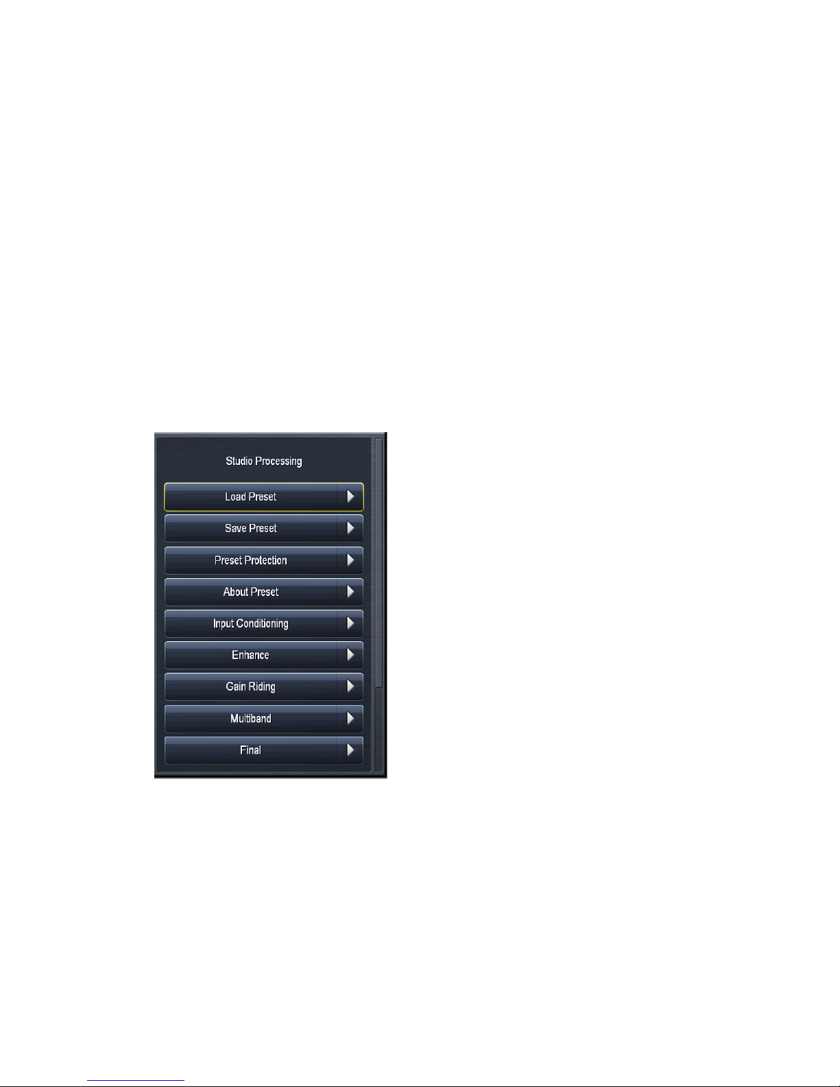
STUDIO PROCESSING MENU
CHAPTER 12 | 72
12
The Studio Processing Core is a low-latency processing core mainly designed for talent monitoring. Its menu
is virtually identical to that of the AM Processing section except for the Band Mix menu which includes a Final
Limiter drive (instead of Clipper driver), an Output Level control to set the final output level, and the option to
bypass the multiband limiters if desired, which further decreases the already low latency throughput time of this
processing section slightly.
Studio Processing Menu
Page 82
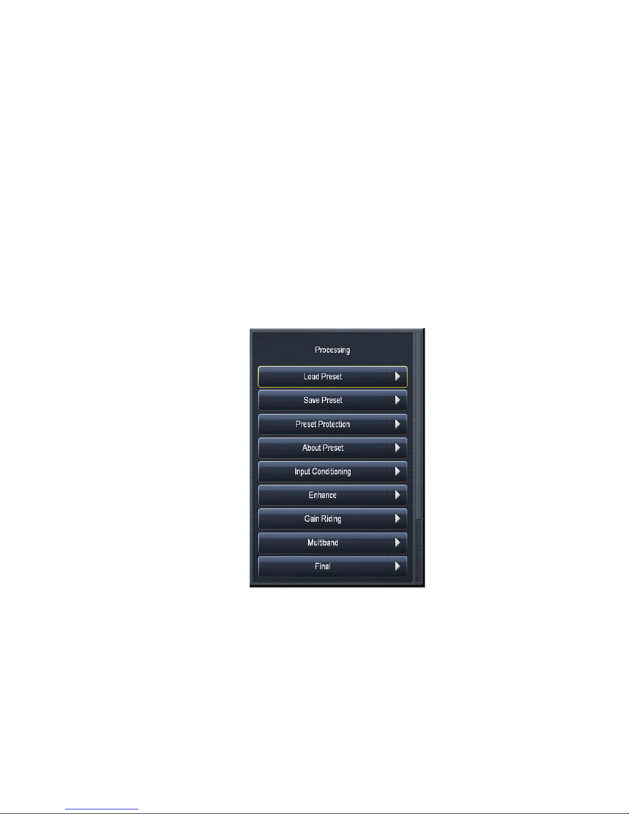
HD PROCESSING MENU
CHAPTER 13 | 73
13
Much like the Studio processing core, the optional HD processing section is virtually identical to its AM counterpart with one significant difference: It uses a look-ahead peak limiter in lieu of a clipper as the final processing
stage.
The HD processing cores are suitable for use in both HD Radio (iBiquity/NRSC-5) and DAB (Eureka 147)
applications depending upon the sample rate established in the System > System Config > Sample Rate menu.
The HD Processing Menu
Page 83
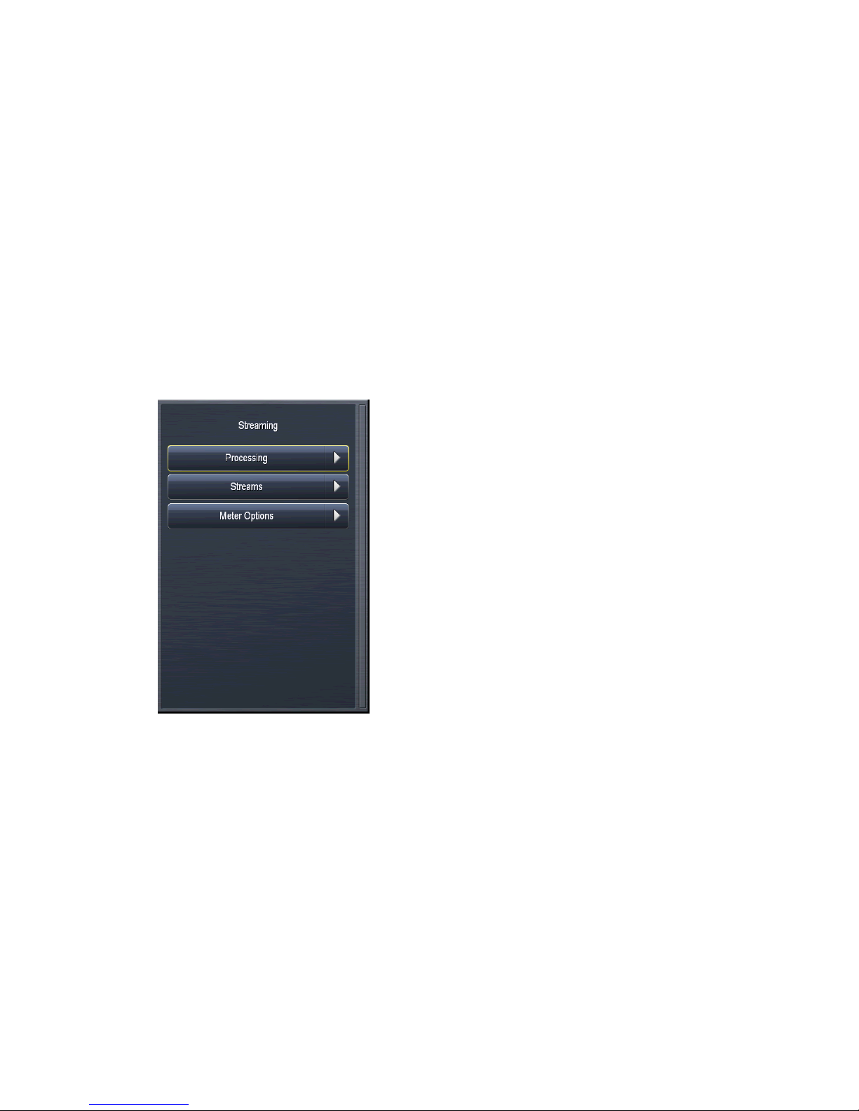
STREAMING MENU
CHAPTER 14 | 74
14
Omnia.7 can be optionally configured to provide independent processing for streaming audio as well as built-in
streaming encoding. The Streaming menu contains sub-menus for processing and for configuring the various
encoder and server options.
The Streaming Menu
A detailed explanation of setting up and configuring streaming encoders and servers would require an entire
manual of its own, and is beyond the scope of the general Omnia.7 manual. We have assumed that users who
stream possess at least a basic knowledge of how streaming audio works and an understanding of the differences
between the various formats. We encourage you to work closely with your IT administrators to obtain the information specific to your operation.
Processing Menu
Much like the Studio and HD processing cores, the streaming processing section is virtually identical to its
AM counterpart with one significant difference: It uses a look-ahead peak limiter in lieu of a clipper as the final
processing stage.
Page 84
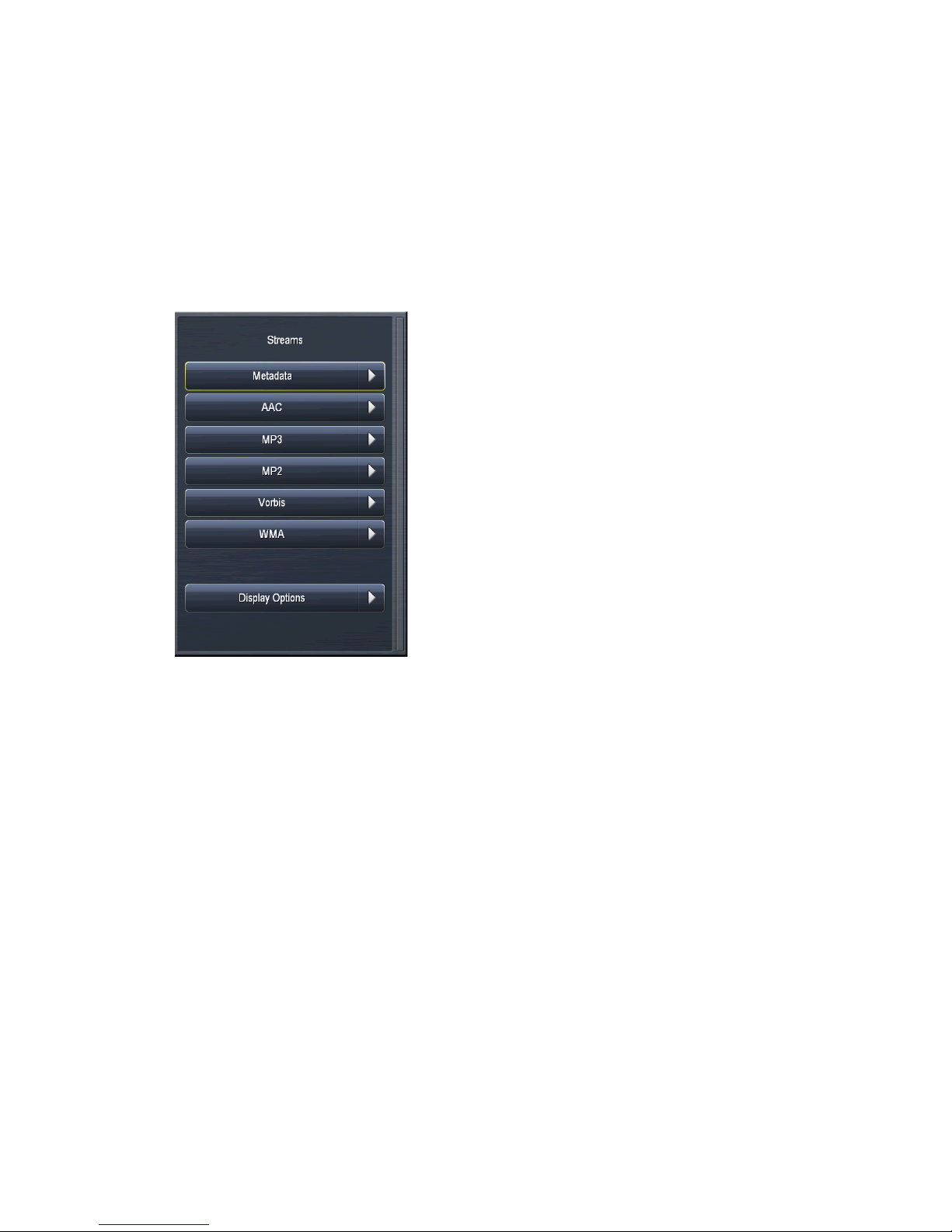
STREAMING MENU
Streams Menu
This menu contains the controls necessary to set up and configure each of the enabled encoders and is where details
of the servers can be entered. The type and maximum number of encoders can be set up in the the System> System
Config> Streaming Encoders menu. For ease of illustration, only one type of each encoder will be shown in the
examples below.
CHAPTER 14 | 75
Metadata Menu
Omnia 7’s built-in http server can be used to feed information such as the song title and artist information to the
stream.
AAC Menu
The AAC menu contains two sub-menus, Encoder and Server.
The Encoder menu allows you to enable or disable the stream, adjust its output gain, enter the stream’s title, and
select the SBR Mode, channel mode, sample rate, bit rate, and audio bandwidth.
Page 85
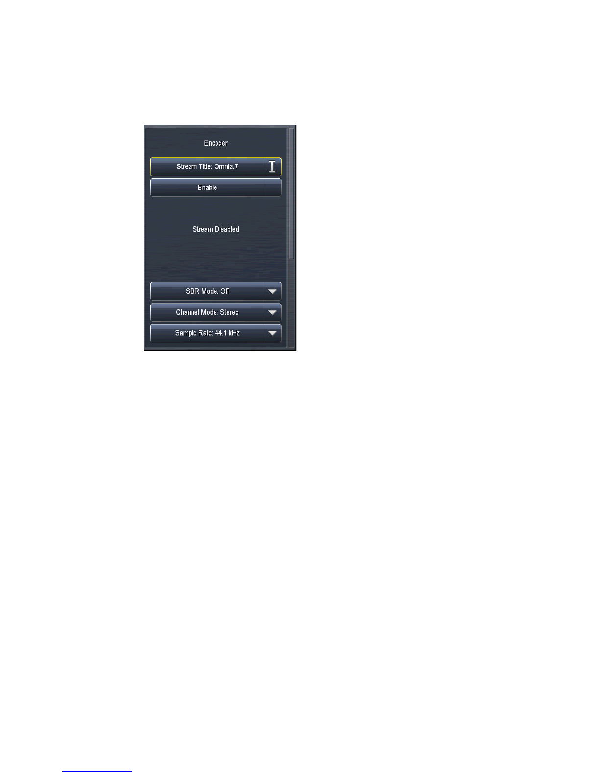
STREAMING MENU
CHAPTER 14 | 76
♦ The Title field allows you to enter the stream title displayed to listeners and on public listings, such as
shoutcast.com.
♦ The Enable control enables or disables the stream. When enabled, the encoder will continually try to
connect to the specified server.
♦ The SBR (Spectral Band Replication) Mode toggles between Off, On, and Oversampled. We recommend
setting this control to Off (AAC) for bit rates of 160kbps or higher, On (AAC+) for bit rates of 96kbps or
lower, and Oversampled for bitrates between 96 and 128kbps.
♦ The Channel Mode menu provides a choice between Mono, Stereo, Stereo Independent, Parametric
Stereo, and Dual Channel. We recommend setting this control to Stereo for bit rates over 40kbps and to
Parametric Stereo for bit rates of 40kbps and lower. Mono should be used only if the program material is
mono. Because the Stereo Independent and Dual Channel settings force the encoder to divide bits equally
between the left and right channels instead of allowing it to allocate the bits as needed, we recommend
not using these settings unless you have a specific reason to do so.
♦ The Bit Rate menu allows you to choose encoding bit rates between 16kbps and 320 kbps. Your choice of
bit rate settings will significantly influence the audio quality of your stream. However, you will also need
to take other factors into consideration, such as the total amount of bandwidth available for the stream,
the anticipated number of users, your maximum upload speed, and the download speed limits of your
intended users.
♦ The Audio Bandwidth menu allows you to set the high frequency range of the stream between 8 and
20kHz. Unless you have a specific reason to set the bandwidth manually, we strongly recommend leaving
this control set to Encoder Default.
♦ The Sample Rate menu will either maintain Omnia.7’s system sample rate of 44.1kHz or 48kHz (depend-
ing on the sample rate setting) in the encoder, or result in a high-quality re-sample to 32, 44.1, or 96kHz.
Page 86
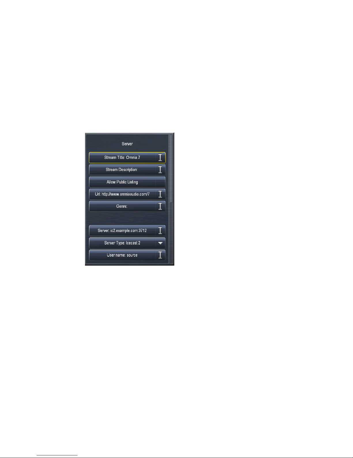
STREAMING MENU
The Server menu allows you to input and set up your server settings.
CHAPTER 14 | 77
♦ The setting of the Gain control is critical. Normally, this control can be left at 0.0. However, there are
times when you will want to reduce the input level into the encoder. For example, if you are employing
a lot of peak limiting in the Streaming core and using AAC+ encoding at a low bit rate, there will be peak
overshoots created as a side effect of the bit rate reduction. Unless the input level into the encoder is
reduced, it will be up to the listener’s decoder to deal with the excessive levels, which will most certainly
degrade the quality of the audio. You may also consider backing off the Final Limiter Drive from within
the Streaming processing core.
♦ The Title field should contain the name of your audio stream.
♦ The Server field should contain the URL of the server, including the port, in the following format:
“streamingserver.example.com:8000”
♦ The Mount Point field (for Icecast 2 servers) should contain the mount point on the server, in the
following format: “/example1.mp3” following the server name.
♦ Enabling the Allow Public Listing control sets the “public listing allowed” flag in the stream, as deter-
mined by the server.
♦ The Server Type control allows you to choose between Shoutcast and Icecast2.
♦ The Mime Type control specifies the HTTP Mime Type of the stream and determines whether Audio/
AAC or Audio/AACP settings are used to provide for player compatibility.
♦ The URL field is a metadata field whose information is sent to the server to be (potentially) displayed in
the listings and player. The URL is typically the station’s official home page.
♦ The User Name field contains the user (log-in) name for the server.
♦ The Password field contains the password for the server.
♦ The Genre field is also a metadata field. The type or style of content found on the stream is typically
entered here.
Page 87
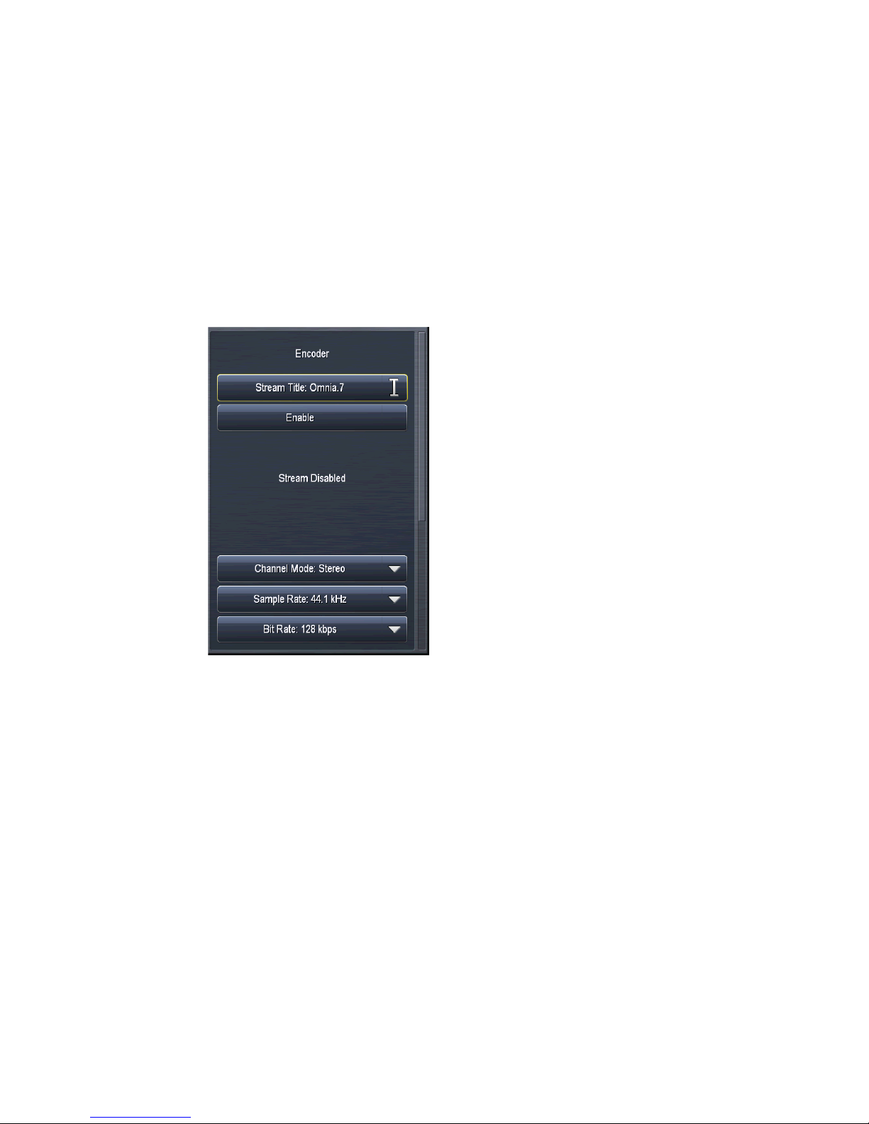
STREAMING MENU
MP3 Menu
The MP3 menu contains two sub-menus, Encoder and Server.
The MP3 Encoder menu allows you to enable or disable the stream, adjust its output gain, enter the stream’s title,
and select the channel mode, sample rate, bit rate, audio bandwidth, and encoding quality.
CHAPTER 14 | 78
♦ The Apply Immediately control determines whether any changes you make to the server settings take
effect immediately or when you manually reconnect.
♦ The Title field allows you to enter the stream title displayed to listeners and on public listings, such as
shoutcast.com.
♦ The Enable control enables or disables the stream. When enabled, the encoder will continually try to
connect to the specified server.
♦ The Channel Mode menu provides a choice between Mono, Stereo, and Stereo Independent. Because the
Stereo Independent settings forces the encoder to divide bits equally between the left and right channels
instead of allowing it to allocate the bits as needed, we recommend not using this settings unless you have
a specific reason to do so.
♦ The Sample Rate menu will either maintain Omnia.7’s system sample rate of 44.1kHz or 48kHz (depend-
ing on the sample rate setting) in the encoder, or result in a high-quality re-sample to 8, 11.025, 12, 16,
22.05, 24, 32kHz.
♦ The Bit Rate menu allows you to choose encoding bit rates between 16kbps and 320 kbps. Your choice of
bit rate settings will significantly influence the audio quality of your stream. However, you will also need
to take other factors into consideration, such as the total amount of bandwidth available for the stream,
the anticipated number of users, your maximum upload speed, and the download speed limits of your
intended users.
♦ The Audio Bandwidth menu allows you to set the high frequency range of the stream between 3 and
20kHZ. Unless you have a specific reason to set the bandwidth manually, we strongly recommend leaving
Page 88
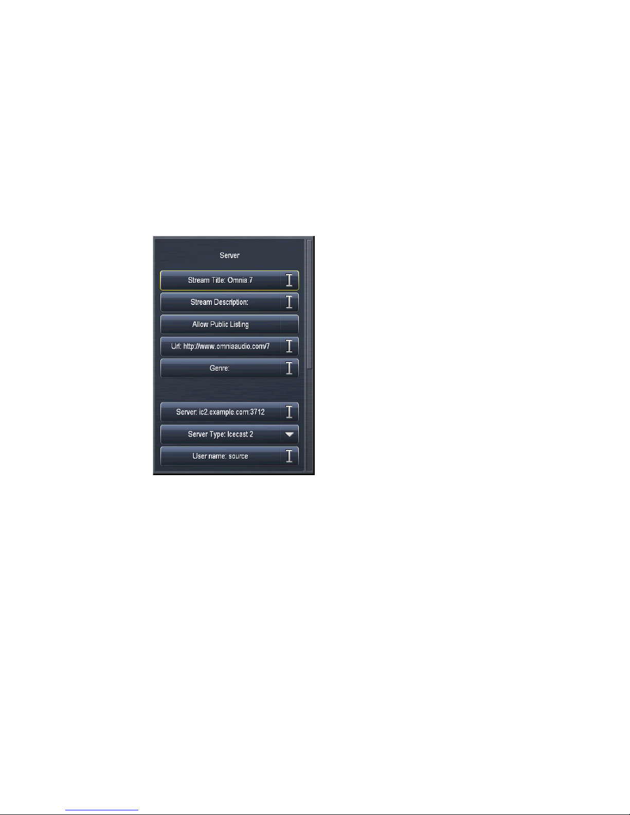
STREAMING MENU
The MP3 Server menu allows you to input and set up your server settings.
CHAPTER 14 | 79
this control set to Encoder Default.
♦ The Encoding Quality menu provides a choice between Best, Normal, and Low CPU which allows you to
balance the tradeoff between higher audio quality and lower CPU usage.
♦ The Gain control determines the final output level into the encoder. If you are encoding to a low bit or
sample rate, you will almost certainly need to turn this down to prevent harsh crackling sounds resulting
from clipping in the receiving decoder.
♦ The Title field allows you to enter the name of the encoder.
♦ The Server field should contain the URL of the server, including the port, in the following format:
“streamingserver.example.com:8000”
♦ The Mount Point field (for Icecast 2 servers) should contain the mount point on the server, in the
following format: “/example1.mp3” following the server name.
♦ Enabling the Allow Public Listing control sets the “public listing allowed” flag in the stream, as deter-
mined by the server.
♦ The Server Type control allows you to choose between Shoutcast and Icecast2.
♦ The URL field is a metadata field whose information is sent to the server to be (potentially) displayed in
the listings and player. The URL is typically the station’s official home page.
♦ The User Name field contains the user (log-in) name for the server.
♦ The Password field contains the password for the server.
♦ The Genre field is also a metadata field. The type or style of content found on the stream is typically
entered here.
♦ The Apply Immediately control determines whether any changes you make to the server settings take
effect immediately or when you manually reconnect.
Page 89
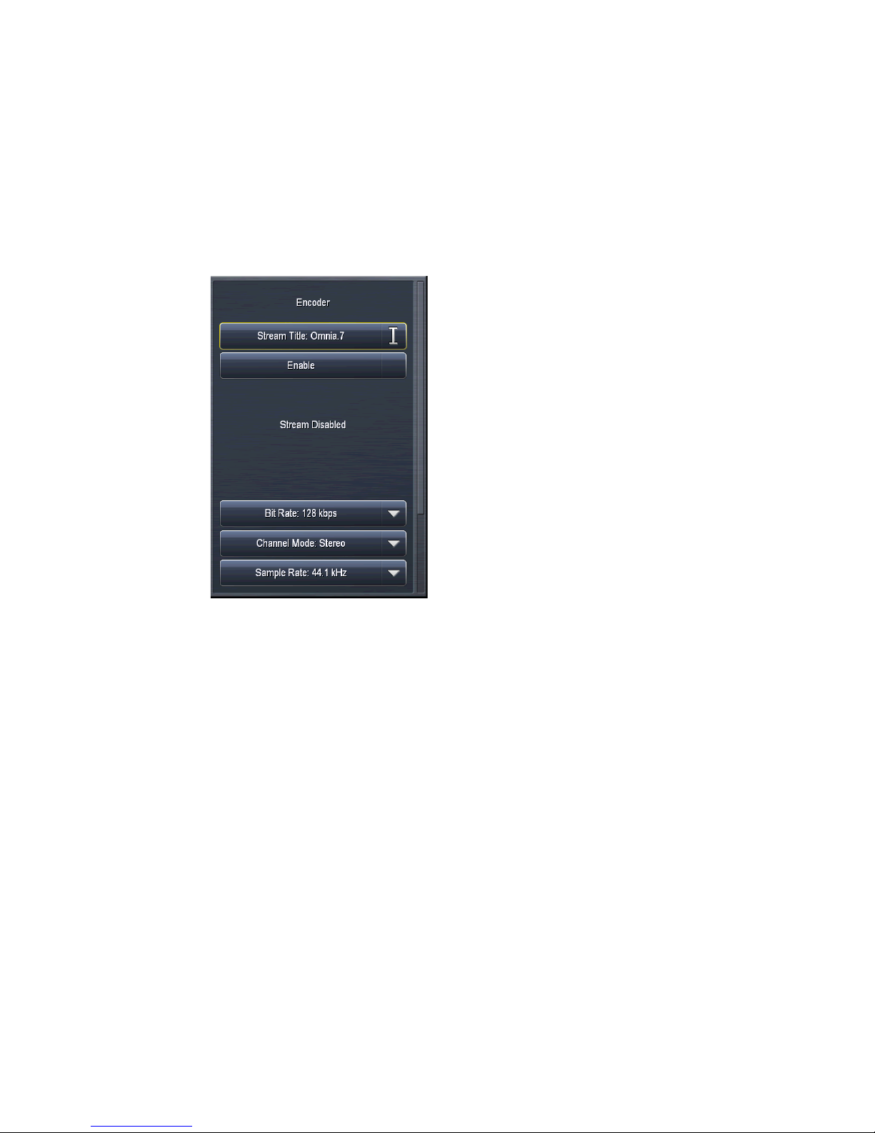
STREAMING MENU
MP2 Menu
The MP2 menu contains two sub-menus, Encoder and Server.
The MP2 Encoder menu allows you to enable or disable the stream, adjust its output gain, enter the stream’s title,
and select the channel mode, sample rate, and bit rate.
CHAPTER 14 | 80
♦ The Title field allows you to enter the stream title displayed to listeners and on public listings, such as
shoutcast.com.
♦ The Enable control enables or disables the stream. When enabled, the encoder will continually try to
connect to the specified server.
♦ The Channel Mode menu provides a choice between Mono, Stereo, Joint Stereo, and Dual Channel.
♦ The Bit Rate menu allows you to choose encoding bit rates between 64kbps and 384kbps. Your choice of
bit rate settings will significantly influence the audio quality of your stream. However, you will also need
to take other factors into consideration, such as the total amount of bandwidth available for the stream,
the anticipated number of users, your maximum upload speed, and the download speed limits of your
intended users.
♦ The Sample Rate menu will either maintain Omnia.9’s system sample rate of 44.1kHz or 48kHz (depend-
ing on the sample rate setting) in the encoder, or result in a high-quality re-sample to 8, 11.025, 12, 16,
22.05, 24, 32kHz.
♦ The Gain control determines the final output level into the encoder.
The MP2 Server menu allows you to input and set up your server settings.
Page 90

STREAMING MENU
CHAPTER 14 | 81
♦ The Title field allows you to enter the stream title displayed to listeners and on public listings, such as
shoutcast.com.
♦ The Server field should contain the URL of the server, including the port, in the following format:
“streamingserver.example.com:8000”
♦ The Mount Point field (for Icecast 2 servers) should contain the mount point on the server, in the
following format: “/example1.mp3” following the server name.
♦ Enabling the Allow Public Listing control sets the “public listing allowed” flag in the stream, as deter-
mined by the server.
♦ The Server Type control allows you to choose between Shoutcast and Icecast2.
♦ The URL field is a metadata field whose information is sent to the server to be (potentially) displayed in
the listings and player. The URL is typically the station’s official home page.
♦ The User Name field contains the user (log-in) name for the server.
♦ The Password field contains the password for the server.
♦ The Genre field is also a metadata field. The type or style of content found on the stream is typically
entered here.
♦ The Apply Immediately control determines whether any changes you make to the server settings take
effect immediately or when you manually reconnect.
Vorbis Menu
The Vorbis menu contains two sub-menus, Encoder and Server.
The Vorbis Encoder menu allows you to enable or disable the stream, adjust its output gain, enter the stream’s title
and Ogg Metadata, and select the channel mode, sample rate, and quality mode.
Page 91
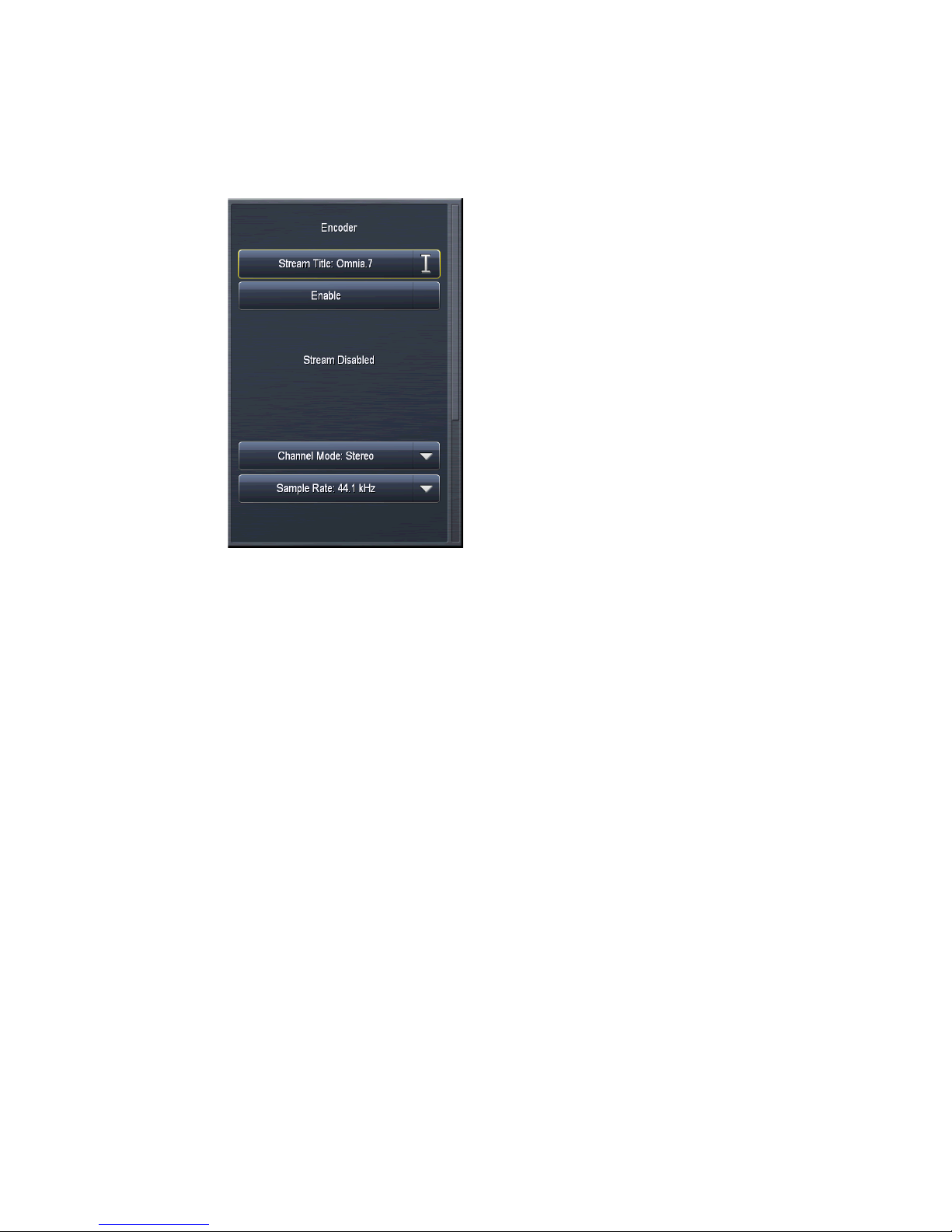
STREAMING MENU
CHAPTER 14 | 82
♦ The Title field allows you to enter the stream title displayed to listeners and on public listings, such as
shoutcast.com.
♦ The Enable control enables or disables the stream. When enabled, the encoder will continually try to
connect to the specified server.
♦ The Channel Mode menu provides a choice between Mono and Stereo.
♦ The Sample Rate menu will either maintain Omnia.9’s sample rate of 44.1kHz or 48kHz (depending on
the sample rate setting)in the encoder, or result in a high-quality re-sample to 8, 11.025, 16, 22.05, 24,
32, or 44.1kHz.
♦ The Quality Mode menu allows you to choose from a range of settings between VBR -2 and VBR 9. The
Vorbis codec is by nature a variable bit rate encoder, but for reference, we have included an approximate
average bit rate for quality modes lower than VBR 4.
♦ The Gain control determines the final output level into the encoder.
Page 92
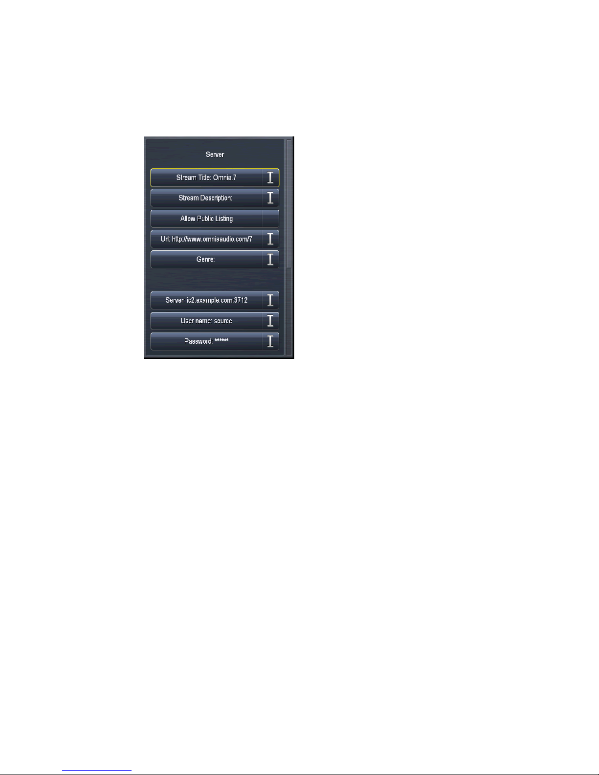
STREAMING MENU
The Vorbis Server menu allows you to input and set up your server settings.
CHAPTER 14 | 83
♦ The Server field should contain the URL of the server, including the port, in the following format:
“streamingserver.example.com:8000”
♦ The Mount Point field (for Icecast 2 servers) should contain the mount point on the server, in the
following format: “/example1.mp3” following the server name.
♦ Enabling the Allow Public Listing control sets the “public listing allowed” flag in the stream, as deter-
mined by the server.
♦ The URL field is a metadata field whose information is sent to the server to be (potentially) displayed in
the listings and player. The URL is typically the station’s official home page.
♦ The User Name field contains the user (log-in) name for the server.
♦ The Password field contains the password for the server.
♦ The Genre field is also a metadata field. The type or style of content found on the stream is typically
entered here.
♦ The Apply Immediately control determines whether any changes you make to the server settings take
effect immediately.
WMA Menu
The WMA menu contains two sub-menus, Encoder and Server.
The WMA (Windows Media Audio) Encoder menu allows you to enable or disable the stream, adjust its output
gain, enter the stream’s title, and select the encoder type and format.
Page 93
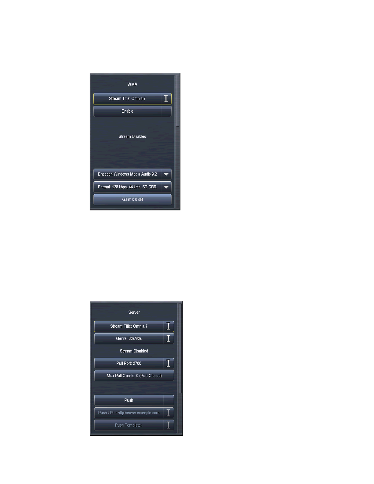
STREAMING MENU
CHAPTER 14 | 84
♦ The Title field allows you to enter the name of the encoder.
♦ The Enable control enables or disables the stream. When enabled, the encoder will continually try to
connect to the specified server.
♦ The Encoder menu lets you choose between Windows Media Audio 9 and Windows Media Audio 9
Professional
♦ The Format menu allows you to choose a combination of bit rates and sample rates to determine the
quality of the audio stream.
♦ The Gain control determines the final output level of the encoder.
The WMA Server menu allows you to input and set up your server settings.
Page 94

STREAMING MENU
CHAPTER 14 | 85
♦ The Title field allows you to enter the name of your audio stream.
♦ The Genre field is also a metadata field. The type or style of content found on the stream is typically
entered here.
♦ The Pull Port field allows you to enter the server’s port number.
♦ The Max Pull Clients control lets you set the maximum number of pull clients. We strongly recommend
against letting listeners through directly without a server in between.
♦ The Push control enables or disables push capabilities outward toward the server, much like Icecast or
Shoutcast. When enabled, fields for providing the Push URL, Template, User Name, and Password are
accessible. Note that the mount point must be part of the server push URL - for example, http://omniaau-
dio.com/mountpoint
Page 95

MONITOR OUTPUT MENU
CHAPTER 15 | 86
15
The Monitor Output menu of Omnia.7 allows you to independently configure the Speaker Output and Headphone
Output. The menus and controls for each of these sections are identical, so any images or references to one apply to
the other.
Monitor Output Menu
Page 96

MONITOR OUTPUT MENU
Speaker/Headphone Output Menus
From here, you can choose which of Omnia.7’s processing cores you wish to monitor, and from within each core,
which specific patch point.
CHAPTER 15 | 87
Additionally, you can Load and Save presets, adjust overall volume levels and individual left and right channel
levels, access the built-in pink noise generators, independently delay the output of the left and right channels,
solo the left and right channels, invert the phase of each channel, couple and un-couple the left and right channels
for delay and EQ, set the frequency of the high pass filter, set the Bass Clip and Limiter thresholds, and access the
loudness and parametric equalizer sections.
Note:
Keep in mind that although some of the features, terms, and tools in the Monitor Output sections
are similar or identical to their counterparts in Omnia.7’s various processing cores - such as the term
“preset” - they have no impact on the air. Monitor Outputs only control what you hear through the
Speaker or Headphone outputs.
Load Preset / Save Preset Menus
These menus work just as their counterparts in the AM, Studio, and HD processing menus.
Page 97

MONITOR OUTPUT MENU
Patch Points Menu
The Patch Point menu lets you choose which of Omnia.7’s processing cores you wish to monitor in the Speaker
and Headphone outputs, and, more specifically, which point within that core you want to hear. The patch point
currently being monitored appears in the corresponding volume control at the top of the screen.
CHAPTER 15 | 88
In a typical radio station scenario, the Speaker Output might be used to feed the control room monitors and the
Headphone Output might be used to feed talent headphones. Each situation and application will be different, and
the choice of how to utilize the monitor outputs is up to you.
One important feature to understand well is the Follow control, which is set to “Off” by default. When Follow
is enabled in a particular user interface on a particular Monitor Output, the patch point (source audio) of that
Monitor Output will conveniently “follow” along with you as you navigate to different processing cores in that user
interface. Keep in mind that anyone else listening to that same Monitor Output will also be affected. The On/Off
status of Follow is independently associated with each remote connection (or the front panel).
AM Processing Patch Points
There are several categories of patch points from which to choose, including I/O, Undo, Miscellaneous, MPX
Decoded, Physical Inputs, Sidechains, and Multiband. The Studio and HD processors have the same or similar
options.
♦ The I/O category lets you listen to Program Input, Loudness Matched A/B, MPX Output, and L/R Output
of the AM processing core.
♦ The Undo category lets you hear audio either before or after the de-clipper, or after the multiband
expander.
♦ The Miscellaneous menu lets you listen to the audio after Input Filtering, after Multiband processing
(Pre Final), after the Bass Clipper, or as an MPX signal with injected noise.
♦ The Physical Inputs menu allows you to monitor the rear-panel Analog or AES inputs.
♦ The Sidechains menu allows you to monitor the audio passing through the Input AGC, Wideband AGC 1,
and Wideband AGC 2 sidechains, as well as the actual output audio from each of those stages.
♦ The Multiband Solo menu allows you to individually monitor the audio in each band of the multiband
AGC.
Page 98

MONITOR OUTPUT MENU
Main Menu
The Main 1 menu contains the controls to set the output level of each Monitor Output, enable or disable any
adjustable parameters of each output, adjust the master gain level, adjust the left and right levels individually, solo
an individual channel, and set a high pass filter frequency for both the left and right channels.
CHAPTER 15 | 89
♦ The Volume slider controls the output level to the speaker or headphone output.
♦ The Bypass control enables or disables the parametric EQ, loudness contours, and high pass filters.
♦ The Lock control allows you to “lock down” all of the settings, including the patch points and the shortcut
settings (such as volume controls) at the top of the user interface. When locked, the controls will appear
grayed out. This is especially useful when the “Follow” control is enabled, as it prevents the selected patch
point from being accidentally changed by someone connected via a remote client.
Note:
Imagine the surprise - not to mention confusion - this would cause the talent if, say, the Speaker
Output, which normally feeds the studio monitors with the low latency Studio output, got switched
over to the HD-2 signal! And while we’re on the subject, let us go on record as stating we do not
endorse the idea of deliberately confusing the talent in this manner. We’re just saying it could
accidentally happen… Ocially, we strongly recommend locking down any monitor output put in
active use.
Page 99

MONITOR OUTPUT MENU
♦ The Pink Noise Left and Pink Noise Right controls turn the pink noise generator in each channel on or
off.
♦ The Left Level and Right Level controls allow you to adjust the output gain of each channel individually
and act as a sort of “balance” control in situations where the left and right speakers are not equally spaced
from the monitor point.
♦ Master Bypass Gain and Left Level and Right Level sliders are also provided when the Monitor Outputs
are in bypass mode.
♦ The Solo Left and Solo Right controls allow you to monitor only the left or only the right channel.
♦ The Left High Pass Filter and Right High Pass Filter controls allow you to set the high pass filter cutoff
point to avoid over-driving small speakers. When calibrating smaller bass-shy speakers, there will come
a point where you can no longer compensate for such a deficiency by EQ-ing, and it is more practical to
simply not try and pass those frequencies at all. That point will be clear on the RTA and is explained in
more detail in the Speaker Calibration section.
There are four additional sub-menus in the Main menu: X-Over, Delay/Phase, Channel Coupling, and Protection
Limiting.
♦ The X-Over menu contains the controls for the Volume-based High Pass Filter.
CHAPTER 15 | 90
¸ The Volume-based High Pass Filter provides a means by which adjust the high pass filter frequency on
the monitor outputs as the volume level is raised. This can help protect smaller monitor speakers by
reducing the amount of low frequency energy routed to them at higher listening levels.
Page 100

MONITOR OUTPUT MENU
♦ In most studios, the left and right speakers are likely to be equidistant from one another and typically
place the talent directly between them. However, in some situations, it may be advantageous to delay
either the right or left channel. The Delay/Phase menu contains the controls necessary to do so.
CHAPTER 15 | 91
¸ The Defeat Delay control turns off the delay entirely to both channels.
¸ The Delay All control allows you to delay the audio output of the Speaker and Headphone outputs.
¸ The Delay Left and Delay Right controls provide a means by which to delay one channel independent-
ly of the other.
¸ The Invert Left and Invert Right controls let you swap the polarity of each channel. The ability to do so
in one channel or the other can be useful if you discover that one of the speakers has been wired out of
phase and it is not practical or convenient to physically switch the positive and negative wires. Being
able to do so to both channels simultaneously can come in handy if you are in a situation where both
channels have gotten out of phase at some point in the studio wiring.
 Loading...