

Page 1
User’s Manual
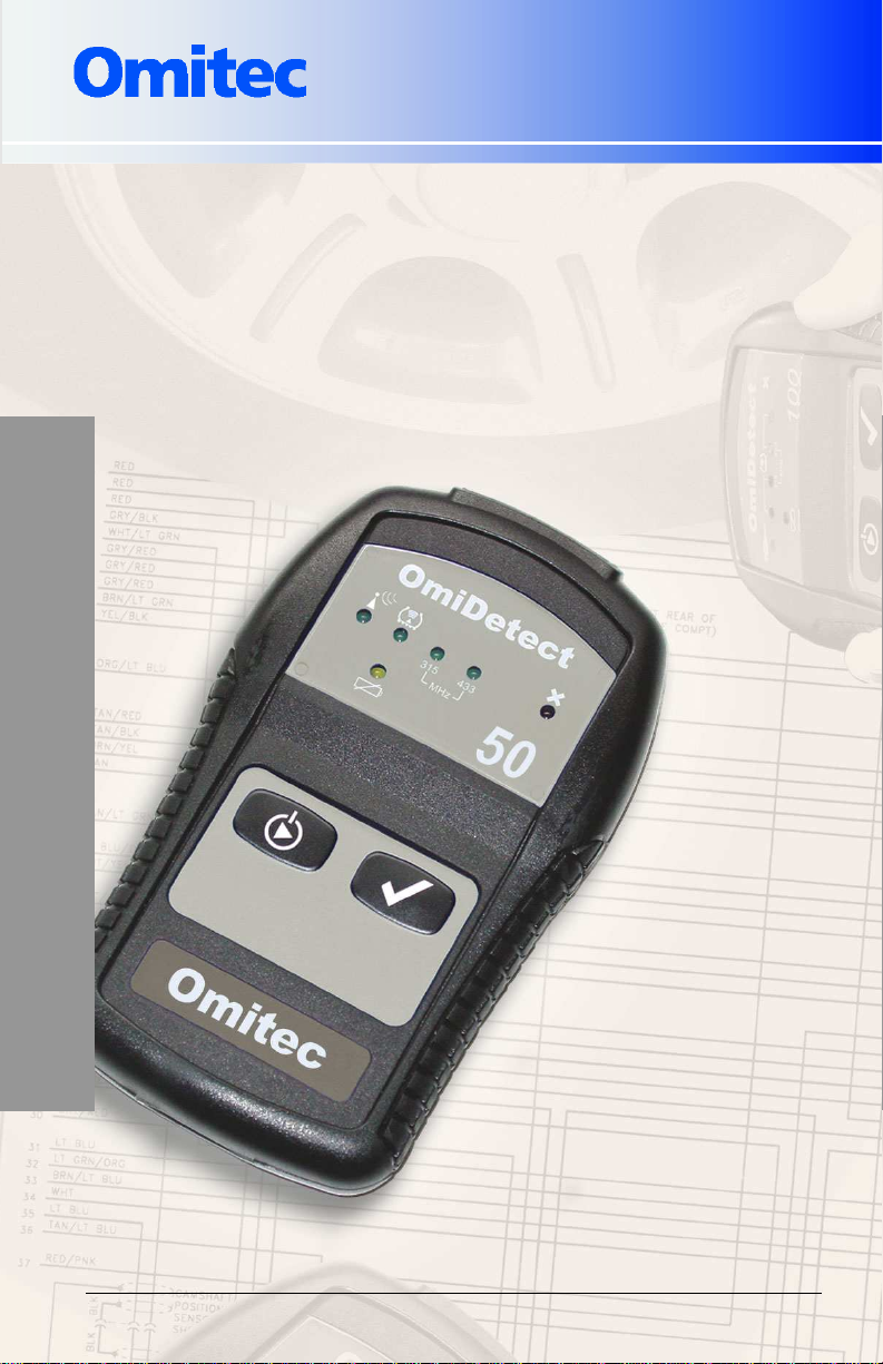
OmiDetect 50
TPM Sensor Tester
CH041006 Rev A.1
OM504/2
Page 2

The information, specifications and illustrations in this manual are based
on the latest information available at the time of publication. The
manufacturer reserves the right to make equipment changes at any time
without notice.
© Copyright 2007 Omitec, Inc.
All rights reserved. OmiDetect is a
registered trademark of Omitec, Inc.
Printed in the U.K.
.
Page 3

OmiDetect 50
Table of Contents
1. INTRODUCTION............................................................................2
Direct Versus Indirect Systems ..................................................3
About Sensors ............................................................................4
Activating Sensors......................................................................4
Reprogramming..........................................................................5
2. SAFETY INFORMATION...............................................................7
3. KIT CONTENTS.............................................................................9
4. CONTROLS AND INDICATORS.................................................10
5. OPERATING INSTRUCTIONS....................................................11
6. WHAT TO DO IF OMIDETECT CANNOT
ACTIVATE THE TPM SENSOR ..................................................14
Technique A..............................................................................14
Technique B..............................................................................14
7. REPROGRAMMING THE TPM CONTROL MODULE................15
8. VEHICLE COVERAGE GUIDE....................................................16
9. SPECIFICATIONS .......................................................................19
10. TROUBLESHOOTING ...............................................................20
11. CARE AND MAINTENANCE .....................................................21
12. WARRANTY...............................................................................21
13. TECHNICAL SUPPORT.............................................................21
Page 4

Introduction
1. Introduction
Congratulations on your purchase of the OmiDetect 50 Tire
Pressure Monitoring (TPM) sensor tester. To enjoy safe and the
best performance from your OmiDetect 50, please read and
follow all instructions, recommendations and warnings.
Understanding the basics of tire pressure monitoring systems
is essential to using the OmiDetect effectively, so be sure to
review the following sections thoroughly.
OmiDetect is a state-of-the-art tester designed especially for
automated and manual testing of Schrader TPM valve sensors for
correct operation. Used properly, it will allow you to quickly:
Confirm that the vehicle’s Schrader TPM sensors are
working properly before you start tire/wheel service work
(including rotating, changing or balancing tires/wheels).
This will reduce the risk of your having to replace a sensor
that was defective prior to your starting the work.
Confirm that the vehicles Schrader TPM sensors are
working properly after you complete tire/wheel service
work.
After rotating the vehicle’s wheels, activate their Schrader
TPM sensors to allow the vehicle control unit monitoring
the TPM sensors to identify their new location.
Diagnose problems with Schrader TPM sensors and other
TPM system components.
Confirm that a Schrader TPM sensor you replaced is
working properly.
Confirm that you installed the correct type of sensor.
History of TPM Systems
In the wake of tire safety issues involving SUVs in the late ‘90s,
Congress passed the Transportation Recall Enhancement,
Accountability, and Documentation (TREAD) Act in 2000. The
TREAD Act mandated that automotive manufacturers start phasing
TPM systems into all their new light vehicles with a GVWR of 10,000
pounds or less beginning in November 2003. By 2006, 90% of all
light vehicles are to comply, and by Sept. 1, 2007, all new light
2
Page 5

Introduction
vehicles must comply. The total population of vehicles with TPM
systems will grow from approximately 4 million units in 2003 to close
to 50 million units by the end of the decade.
The NHTSA, which is responsible for establishing and enforcing
vehicle safety standards, published a mandate requiring that the
TPM system must be capable of monitoring all four tires and alerting
the driver if a tire is under inflated by 25% or more of the OEM’s
recommended tire pressure. Testing showed that proper tire inflation
significantly improves vehicle handling safety, decreases tread wear,
improves fuel economy, and decreases stopping distances.
Underinflated tires are dangerous because they build up internal
heat that can damage the tire structure, potentially resulting in fatal
blowouts.
Direct Versus Indirect Systems
The NHTSA’s mandate on TPM systems allows two system
architectures. The first, called the “direct” system, uses a direct RF
link from each wheel to a central receiving control unit, and the
second, called the "indirect" system, works in conjunction with the
vehicle's antilock-braking (ABS) system.
Direct Systems. Wireless sensor in or on each wheel that
measures internal tire air pressure and temperature
separately and communicates the readings by RF signals
to a receiver/controller control unit at regular intervals. The
sensors have an integral low frequency transmitter and
are typically built into or mounted on the valve stem. The
end of the valve stem serves as the sensor’s antenna.
Most direct systems share the receiver control unit with
the vehicle’s keyless entry system.
Indirect Systems. Monitors rotation of tires via the
vehicle’s antilock braking system (ABS) to calculate
whether they are properly inflated. Does not measure tire
pressure or temperature. The system measures the wheel
speed of all four tires and calculates a “rolling
circumference” for each one. In the event of a tire
pressure loss, the rolling circumference of that tire is
reduced, producing a change in the tire’s rotational speed.
The NHTSA found that direct TPM systems are preferred
because they are better able to detect under- or overinflation and are quicker to provide alerts. Virtually all
vehicle manufacturers today have moved to direct
systems.
3
Page 6

Introduction
Schrader TPM Sensor
Vehicle manufacturers using Schrader TPM sensors:
Ford
Chrysler
GM
Infiniti
Mitsubishi
Nissan
Saab
Volvo
About Sensors
TPM sensors are micromechanical devices (a silicon-based vacuum
cell) powered by a lithium battery with a minimum life expectancy of
up to 10 years. Using their piezoresistive technology, they monitor
tire pressure via measuring the deformation of an internal
diaphragm.
They typically transmit measurement values and sensor ID data at
433 MHz (for European systems) or 315 MHz (for U.S. systems) to
the receiver control unit once per hour when the vehicle is parked
(and only if the pressure changes), to preserve battery life, and
every few seconds when the vehicle is traveling above a certain
speed (typically about 20 mph). If the tire pressure rises or falls
outside calibration limits, a warning light or message is displayed in
real time on the vehicle’s instrument panel, along with an audible
warning, to alert the driver.
Activating Sensors
To activate, or “wake up,” a TPM sensor to test its ability to sense
and transmit tire pressure and sensor ID information to the TPM
control module, you must use one of three different methods,
depending on the type/brand of sensor:
4
Page 7

Introduction
Send the sensor a 125 KHz “continuous” wave command
signal ( ).
Send the sensor a 125 KHz “modulated” wave command
signal ( ).
Position the magnetic tool specified by the OEM in close
proximity to the sensor. The tool is provided with the
vehicle or is available from the OEM.
OmiDetect 50 can activate only sensors capable of being activated
with a continuous wave command signal, primarily Schrader
sensors. Many current-generation sensors can be activated using
that method.
Once a sensor is activated, OmiDetect will listen for the appropriate
response signal. If it detects a valid signal, it will provide both visual
and audible confirmation and indicate its frequency (either 315 MHz
or 434 MHz).
Note: Older generation sensors may not have the electronics
required to activate them using these methods.
Reprogramming
Each TPM sensor has a unique internal identification code. With
most current generation TPM systems, anytime you rotate a
vehicle’s tires or replace one or more TPM sensors, you must “reset”
(reprogram) the TPM system’s control module by placing it in the
“learn” mode and activating each sensor so the control module can
identify the new sensor locations. Refer to the Omitec TPM System
Quick Reference Guide provided with your OmiDetect system for
instructions on how to reset the TPM system of a specific vehicle
make and model.
IMPORTANT: If you do not reprogram the control module, it will
continue to report the correct tire pressures, but will assign
them to the wrong wheel locations.
Other Cases Where You Will Need to Reprogram the TPM Control
Module
If the vehicle’s battery or the TPM control module is disconnected or
the voltage to the TPM system drops below a certain value, the
control module will loose all its sensor ID information and will set a
5
Page 8
Introduction
DTC for a TPM fault. In this case, you will need to reprogram the
control module and clear the DTC.
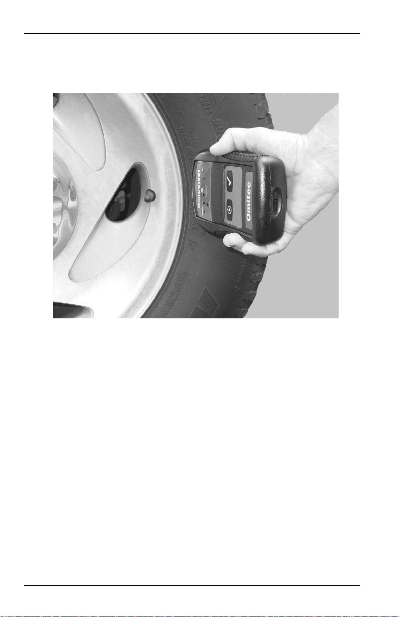
Figure 1. OmiDetect shown in use in testing a TPM sensor.
6
Page 9

Safety Information
2. Safety Information
IMPORTANT SAFETY NOTICE
For your safety, read this manual thoroughly before operating your
OmiDetect system. It is intended for use by properly trained
professional automotive technicians. The safety messages
presented below and throughout this user’s manual are reminders to
the operator to exercise care when using it. Before using your
OmiDetect system, always refer to and follow the safety messages
and applicable service procedures provided by the manufacturer of
the vehicle being serviced.
WARNING – Risk of injury
●
This device emits an electromagnetic field which may interfere with
the safe operation of medial equipment such as a heart pacemaker.
Individuals fitted with a pacemaker should never use this device.
WARNING – Risk of injury
●
Never contact the OmiDetect tester to moving components, drive
belts and other moving components.
WARNING – Risk of electrical shock
●
To avoid possible serious injury from electrical shock, never contact
OmiDetect to electrical components.
CAUTION – General Safety Precautions
●
1. Do not attempt to use the Tire Pressure Monitor System while
adjusting tire pressures, since they do not function as a realtime tire pressure gauge.
2. Tire pressure monitor equipment was calibrated for the original
vehicle tire size. Use only original tire sizes to maintain system
accuracy.
3. Tire sealants should not be used on vehicles equipped with a
Tire Pressure Monitor System. Those sealants can clog the
sensors, rendering them ineffective.
4. Do not attempt to install a tire pressure sensor in a steel or
aftermarket wheel. Tire pressure monitor equipment is only to
be used on original style factory wheels.
5. Always replace a damaged or inoperative TPM
sensor/transmitter.
7
Page 10

Safety Information
6. Never clean a TPM sensor/transmitter with compressed air or
steam. Damage to the sensor/transmitter may result.
7. The cap on the valve stem or a TPM sensor/transmitter
frequently contains a O-ring to prevent contamination and
moisture from entering. Be sure to retain this cap for reuse.
8. Strong radio waves may interfere with the proper operation of
some TPM systems.
9. Snow, ice or mud in the wheel wells and tire chains mounted
on the tires may cause a TPM system to malfunction.
10. Check that the vehicle’s ignition is Off and that its parking
brake is properly set.
11. Do all testing in a well-ventilated area.
12. Do not smoke or allow sparks or open flame near fuel system
parts.
13. Do not smoke or allow open flame near a battery.
14. Do not wear watches, rings or loose-fitting clothing when
working near operating equipment.
15. Wear safety goggles at all times while operating OmiDetect.
Rotating equipment components or electrical equipment can
cause flying particles.
CAUTION – General Operating Precautions
●
1. Keep OmiDetect away from metal objects, such as clamps,
wheel alignment or other tire/wheel equipment, since they will
impede OmiDetect’s ability to receive a good RF signal from a
TPM sensor.
2. Keep OmiDetect away from any known RF transmitters, such
as mobile phones and other RKE (Remote Keyless Entry)
transmitters. Signals received from these devices could result
in the incorrect RF signal being detected.
8
Caution – Misdiagnosis may lead to incorrect or improper
●
adjustment and/or repair.
1. Do not rely on erratic, questionable or obviously erroneous test
information or results. If test information or results are erratic,
questionable or obviously erroneous, verify that the test
procedure was performed correctly. If test information or
results are still suspicious, do not use them for diagnosis.
Improper adjustment or repair may cause equipment damage
or unsafe operation.
Page 11

Safety Information
Kit Contents
Your OmiDetect 50 kit includes:
OmiDetect 50 TPM Sensor Tester
9V 6LR61 Battery
OmiDetect 50 User’s Manual
OmiDetect’s internal 9 volt battery
Important: Your OmiDetect system’s internal 9 volt alkaline battery
must have sufficient charge for the system to work properly. If it
drops below the minimum required, after you power the tester on, it
will sound a constant tone and illuminate the Low Battery Indicator
LED (see Sec. 4) for 5 seconds, then the system will automatically
power Off. OmiDetect will not indicate a valid test result when the
battery is low.
For optimum performance, the recommended batteries are PP3, IEC
6LR61 or 6F22. Do not dispose of batteries in household refuge.
Some communities offer recycling or collection of alkaline batteries.
Contact your local government for disposal practices in your area.
To replace the battery:
1.
Remove battery compartment door from back of unit
and check that the 9V alkaline battery is properly
connected to the battery wiring harness connector.
2. Replace battery compartment door.
9
Page 12

Setup Procedure
3. Controls and Indicators
OmiDetect’s display has a series of 6 LEDs and a Low Battery
Indicator LED.
Figure 2. OmiDetect 50's LED Display.
The 6 LEDs have three functions:
10
The first LED (1) illuminates when the “Listen” mode is
selected, letting you test a TPM sensor activated
manually, rather than electronically using OmiDetect.
The second LED (2) indicates the TPM sensor mode. In
this mode OmiDetect will activate a Schrader valve by
transmitting a continuous RF signal.
The middle two LEDs (3) indicate the frequency of the
response RF signal detected from the TPM sensor under
test, either 315MHz or 433MHz.
The next LED (4) illuminates to indicate a valid sensor
signal was not detected during the test cycle.
Note : On power On OmiDetect automatically reverts to
the last test mode used.
The Low Battery Indicator LED (5) illuminates to
indicate OmiDetect’s internal 9 volt battery is low
and should be replaced (see preceding section).
Page 13

Setup Procedure
Keypad Buttons
Press to power On/Off the tester and to select
TPM sensor Mode. Also lets you select the
“Listen” mode to test sensors activated
manually, rather than electronically using
OmiDetect.
Press to start testing, causing OmiDetect to
activate the TPM sensor and listen for a valid
response RF signal from it.
4. Operating Instructions
When operating OmiDetect to test a Schrader TPM sensor for
proper operation, you will always perform these steps:
1.
Confirm that the vehicle is equipped with Schrader TPM
sensors. For help identifying the type of sensor installed
on the vehicle, refer to Sec. 8, Vehicle Coverage Guide,
or to the vehicle manufacturer’s appropriate service
information.
2.
Hold the front end of OmiDetect on or close to the
tirewall, where it meets the wheel rim, directly below the
sensor.
Important: Do not aim directly at the valve stem. Since it
is metal, it will impede receiving a good RF signal from
the sensor. With low-profile tires, since the area for the
11
Page 14

Setup Procedure
RF signal to penetrate the sidewall is small, carefully
aim OmiDetect halfway between the tire rim and the tire
tread.
12
3.
Power On the OmiDetect tester, by pressing and holding
down the power On/Off button for 2 or 3 seconds. You
will hear a beep and the LED array will illuminate and
display the last test mode used.
4.
Select TPM sensor mode by pressing the power On/Off
button until the LED under the Tire symbol illuminates.
With each press of the power On/Off button, you will
hear a beep and the LED display will alternate between
the Listen and the TPM sensor mode LEDs.
Important: As a battery life saving feature, if you do not
select a sensor type within 30 seconds of powering On
OmiDetect, it will assume no testing is required and
automatically power itself Off.
If the sensor you are testing is not currently supported
by OmiDetect, refer to Sec. 6 for information on how you
can activate the sensor manually.
5.
Press the button to test the sensor. The TPM LED
illuminated will begin to flash to indicate OmiDetect is
activating the sensor and listening for the appropriate
RF signal from it.
Page 15

Setup Procedure
Once OmiDetect detects the appropriate response
signal, it will beep 3 times, the LEDs will stop flashing,
and the LED for the frequency of the response signal it
detected (either 315MHz or 433MHz) will illuminate for 5
seconds to indicate the sensor is operating properly. If it
does not detect the appropriate signal, you will hear a
continuous beep and the X LED will illuminate
continuously, indicating the sensor is not operating
properly. OmiDetect will then reset itself back to the last
test mode used ready for the next test.
If OmiDetect is unable to activate the sensor, be sure to
confirm that you selected the correct sensor type for
testing. Also, remember that some sensors cannot be
activated electronically and must be activated
magnetically. (Refer to the Omitec TPM System Quick
Reference Guide for information on whether the sensor
must be activated magnetically.) If necessary, you can
activate a sensor manually using one of the techniques
outlined in the following section.
To cancel a test once it has started, simply press and
hold down the Power On/Off button for 3 seconds.
OmiDetect will then automatically power itself Off.
Important: If the wheel service work you are performing
on the vehicle includes rotating the tires or replacing a
TPM sensor, with most TPM systems you must
reprogram the TPM control module so it can identify the
new TPM sensor locations, covered in Section 6.
13
Page 16

Setup Procedure
5. What to Do If OmiDetect Cannot Activate
the TPM Sensor
If OmiDetect is unable to activate a TPM sensor, you can use either
of the two following techniques to manually activate it to allow you to
test it for proper operation.
Technique A
1.
Depress the tire’s valve stem to release air pressure for
about 5 to 8 seconds. The TPM sensor will detect the
loss of tire pressure, causing it to transmit a signal to the
vehicle’s TPM control module.
2.
Power On the OmiDetect tester (if necessary repeatedly
press the power On/Off Button until the first LED
illuminates). Then press the button to put OmiDetect
in the “listening” mode for manual testing. The LED will
begin to flash, indicating OmiDetect is listening for an
RF transmission signal from the TPM sensor.
If OmiDetect detects a valid signal, it will beep 3 times
and illuminate the appropriate signal frequency LED for
5 seconds.
Technique B
14
1.
Using a tire/wheel balancer, spin the tire/wheel at the
speed required to cause the TPM sensor to start
transmitting tire pressure measurement signals to the
vehicle’s TPM control module.
Note: Recall that all TPM systems automatically start
transmitting pressure measurement and sensor ID data
every few seconds when the tire is rotating above a
certain speed, typically about 20 mph.
2.
Power On the OmiDetect tester (if necessary repeatedly
press Power ON/OFF button until the first LED
illuminates). Then press the button to put OmiDetect
in the “listening” mode for manual testing. The LED will
begin to flash, indicating OmiDetect is listening for an
RF transmission signal from the TPM sensor.
Page 17

Setup Procedure
If OmiDetect detects a valid signal, it will beep 3 times
and illuminate the appropriate signal frequency LED for
5 seconds.
6. Reprogramming the TPM Control Module
With most current generation TPM systems you will need to
reprogram, or reset, the vehicle’s TPM control module any time:
You rotate a vehicle’s tires
You replace one or more TPM sensors, you must “reset”
(reprogram) the TPM system’s control module by placing it
in the “learn” mode and activating each sensor so the
control module can identify the new sensor locations.
The vehicle’s battery or the control module is
disconnected or the voltage to the TPM system drops
below a certain value, causing the control module to loose
all its sensor ID information. (This will set a DTC for a
TPM fault. In addition to reprogramming the control
module, you also will need to clear the DTC.)
IMPORTANT: If you do not reprogram the control module, it will
continue to report the correct tire pressures, but will assign
them to the wrong wheel locations.
To reprogram the TPM control module:
1.
Place the vehicle’s TPM control module in the “learn”
mode. (The procedure required varies with vehicle
makes and models. Refer to the Omitec TPM System
Quick Reference Guide provided with your OmiDetect
system for the procedure required for the vehicle you
are servicing.)
2.
Activate each TPM sensor (see Section 5), following the
vehicle manufacturer’s requirements for the order in
which the sensors are to be activated. With most vehicle
makes/models you will be required to start with the front
left wheel, followed by the right front, right rear, left rear,
and spare tire, working clockwise around the vehicle.
Typically, the vehicle will sound a series of two or more
horn beeps to confirm its TPM control module was able
to communicate with the TPM sensor and identify the
sensor’s location.
15
Page 18

Setup Procedure
When finished activating all the TPM sensors, you may
be required to drive the vehicle a specified distance and
speed in order for the TPM control module to store the
current tire pressures as new setpoints to be monitored.
Refer to your Omitec TPM System Quick Reference
Guide for more information.
7. Vehicle Coverage Guide
OmiDetect 50 can test only vehicles fitted with Schrader TPMS
sensors. As a broad guide, the table below lists some of the vehicle
manufacturers using Schrader TPMS sensors (black filled circle
indicates LED illuminated).
Vehicle
Manufacturer
Chrysler
16
OmiDetect 50 TPMS Vehicle Coverage List
Model Years TPMS Sensor
300M 2002 - 2005 Schrader
Crossfire 2004 - 2006 Schrader
Grand Cherokee 2002 - 2004 Schrader
Grand Cherokee 2005 - 2006 Schrader
Liberty 2002 - 2004 Schrader
Liberty 2005 - 2006 Schrader
Pacifica 2002 - 2005 Schrader
Activated
Manually
Must Be
Magnet
required
Magnet
required
Magnet
required
Magnet
required
Magnet
required
Page 19

Setup Procedure
Ford
GM
Prowler 2002 - 2003 Schrader
Caravan 2002 - 2003 Schrader
Caravan 2004 - 2006 Schrader
RS Minivan 2002 - 2005 Schrader
Town & Country 2002 - 2003 Schrader
Town & Country 2004 - 2006 Schrader
Aviator 2003 - 2005 Schrader
Crown Victoria 2005 - 2006 Schrader
Escape 2005 - 2006 Schrader
Expedition 2003 - 2006 Schrader
Explorer 2003 - 2005 Schrader
Freestar 2004 - 2006 Schrader
Mark Lt 2005 - 2006 Schrader
Mercury 2005 - 2006 Schrader
Navigator 2004 - 2006 Schrader
Ranger 2004 - 2006 Schrader
Town Car 2005 - 2006 Schrader
Chevrolet
Avalanche
Cadillac SRX 2004 - 2006 Schrader
Cadillac STS 2005 - 2006 Schrader
Cadillac XLR 2004 - 2006 Schrader
Envoy XL 2006 Schrader
Escalade 2005 - 2006 Schrader
Escalade EXT 2006 Schrader
Escalade ESV 2004 - 2006 Schrader
Impala 2005 - 2006 Schrader
Monte Carlo 2005 - 2006 Schrader
Ranier 2006 Schrader
Sierra 2006 Schrader
Silverado 2004 - 2006 Schrader
Suburban 2004 - 2006 Schrader
Tahoe 2005 - 2006 Schrader
Trailblazer 2006 Schrader
2004 - 2006 Schrader
Magnet
required
Magnet
required
Magnet
required
Magnet
required
Magnet
required
Magnet
required
Magnet
required
Magnet
required
Magnet
required
17
Page 20

Setup Procedure
Infiniti
Mitsubishi
Nissan
Saab
Volvo
Yukon 2005 - 2006 Schrader
Yukon XL 2006
M35
QX56
Q45
G35
Endeavour
Galant
350Z
Altima
Armada
Frontier
Maxima
Murano
Pathfinder
Quest
Sentra
Titan
Xterra
9-3 2004 - 2006 Schrader
S60
S80
V70
XC70
XC90
2005 - 2006
2005 - 2006
2005 - 2006
2005 - 2006
2004 - 2006
2004 - 2006
2005 - 2006
2005 - 2006
2005 - 2006
2005 - 2006
2005 - 2006
2005 - 2006
2005 - 2006
2005 - 2006
2005 - 2006
2005 - 2006
2005 - 2006
2004 - 2006
2004 - 2006
2004 - 2006
2004 - 2006
2004 - 2006
Schrader
Schrader
Schrader
Schrader
Schrader
Schrader
Schrader
Schrader
Schrader
Schrader
Schrader
Schrader
Schrader
Schrader
Schrader
Schrader
Schrader
Schrader
Schrader
Schrader
Schrader
Schrader
18
Page 21

Setup Procedure
8.
8. S
Specifications
8.8.
SS
TPMS Valve Sensor
Activation
Activation Range
Activation Format
RF Detection
Frequencies
Power
Approvals FCC
Inductively Coupled RF at 125KHz
2” – 8” (50mm – 200mm) depending
on sensor and wheel type
Continuous Frequency
315 MHz & 433.92 MHz
9V Battery (Alkaline/Manganese)
PP3, IEC 6LR61 or 6F22
Note: Do not use rechargeable
batteries. Dispose of used batteries
in accordance with local authority
guidelines.
This device complies with Part 15 of
the FCC rules. Operation is subject to
the following two conditions:
Industry Canada:
RSS210, RSSGEN
• This device may cause harmful
interference, and
• This device must accept
interference received, including
interference that may cause
undesired operation.
19
Page 22

Troubleshooting
9. Troubleshooting
Problem: Unable to activate a TPM sensor.
Possible solution: Confirm that the vehicle is equipped
with Schrader TPM sensors. Remember: OmiDetect
50 can activate only sensors capable of being
activated with a continuous wave signal command.
Possible solution: When aiming OmiDetect, be sure to
hold it on or close to the tire wall where it meets the
wheel rim, directly below the sensor. Do not aim
directly at the valve stem, since it is metal and will
impede receiving a good RF signal from the sensor.
Possible solution: If you are testing/activating a TPM
sensor fitted to a low-profile tire/wheel, be sure to
carefully aim OmiDetect at the tire sidewall area
halfway between the tire rim and the tire tread.
Possible solution: If you are testing an older-generation
sensor, you may have to activate it magnetically,
rather than electronically using OmiDetect. Refer to
the Omitec TPM System Quick Reference Guide or
to the vehicle manufacturer’s appropriate service
information to confirm the type of sensor installed on
the tire/wheel and how you activate it.
Possible solution: The sensor may be defective and have
to be replaced.
20
Problem: Inconsistent test results.
Possible solution: OmiDetect will not indicate a valid test
result when the battery is low (see Sec. 0).
Problem: OmiDetect power’s Off shortly after I power it On.
Possible solution: As a battery life saving feature, if you
do not select a sensor type within 30 seconds of
powering on OmiDetect, it will assume no testing is
required and automatically power itself Off. Also,
once OmiDetect completes a test cycle, it will
indicate whether it detected a valid signal and then
automatically power itself Off after 5 seconds.
Possible solution: The tool’s internal 9 volt alkaline
battery may be low and need to be replaced. When
the battery is low, after you power the tool On, it will
Page 23

Operating Tips
sound a constant tone and illuminate the Low Battery
Indicator LED (see Sec. 3) for 5 seconds, then the
system will automatically power Off.
Problem: OmiDetect will not power On.
Possible solution: The tool’s internal 9 volt alkaline
battery may be low and need to be replaced (see
above).
10. Care and Maintenance
Your OmiDetect system should be cared for like any other
piece of high-quality electrical equipment.
To maintain the condition and serviceability of the system,
you should periodically inspect and clean all the system
components as necessary.
Never spray any liquid directly on the system. Instead,
moisten a soft cloth with water and a mild cleaning agent
like window cleaning solution, then wipe the units clean.
The system’s internal 9 volt battery should be removed if
the system is not used for extended periods.
Use only a standard 9V alkaline battery when replacing it.
The system does not need any adjustments or calibration.
11. Warranty
The OmiDetect 50 TPM Sensor Tester has a one-year warranty
against defects in workmanship and materials (excluding batteries).
Any defective item returned within this time showing signs of abuse,
tampering, neglect or misuse will be repaired at normal time and
material costs.
12. Technical Support
Technical support is available from Monday through Friday from
8:00 a.m. to 5:00 p.m. EDT by calling OmiDetect Technical Support
toll-free at 1-800-434-6744 or by emailing
techsupportusa@omitec.com.
21
Page 24

Notes:
Page 25

Page 26

29777 Telegraph Road, Onyx Plaza, Ste. 1637
Southfield, MI 48034
Phone: (248) 799-2000
Technical support: (800) 434-6744
Email: techsupport@omitecusa.com
Web site: www.omitecusa.com
 Loading...