

OTMC 100
User Manual
Smart Measurement Solutions

Manual Version: OTMC100.AE.1
© OMICRON Lab 2012. All rights reserved.
This user manual manual is a publication of OMICRON electronics GmbH.
This user manual represents the technical status at the time of printing. The product information,
specifications, and all technical data contained within this user manual are not contractually binding.
OMICRON electronics reserves the right to make changes at any time to the technology and/or
configuration without announcement. OMICRON electronics is not to be held liable for statements and
declarations given in this user manual. The user is responsible for every application described in this
user manual and its results. OMICRON electronics explicitly exonerates itself from all liability for
mistakes in this manual.
Please feel free to copy and print this manual for your needs.
Windows is a registered trademark of Microsoft Corporation. Apple and Bonjour are registered
trademarks of Apple Inc. OMICRON Lab and Smart Measurement Solutions are registered trademarks
of OMICRON electronics GmbH.
OTMC 100 Series User Manual
2

Contents
Preface & General Safety Instructions ...................................................... 6
1 Introduction & Designated Use .................................................................. 7
2 Scope of Delivery, Ordering Information, Accessories ........................... 10
3 Device Overview .......................................................................................... 12
4 Mounting ...................................................................................................... 14
4.1 Safety Instructions ............................................................................... 14
4.2 Suitable Mounting Positions ................................................................ 14
4.3 Mounting Instructions ........................................................................... 16
4.3.1 Mounting Instructions for Mast Mounting .................................. 16
4.3.2 Mounting Instructions for Temporary Mounting Using the 1/4"
BSW Thread ............................................................................. 18
5 Connection, Access & Initial Setup ........................................................... 19
5.1 Connecting the OTMC 100 to an Ethernet Network ............................ 19
5.2 Accessing the OTMC 100 from a Computer ........................................ 21
5.2.1 System Requirements .............................................................. 21
5.2.2 Accessing the OTMC 100 Web Interface ................................. 21
5.3 Next Steps to Set Up the OTMC 100 ................................................... 24
6 Operating the OTMC 100 ............................................................................ 27
6.1 Operating Procedures Performed via the Web Interface ..................... 27
6.1.1 Viewing the GPS, PTP, NTP and Network Status .................... 27
6.1.2 Defining a Password ................................................................. 27
6.1.3 Running a Software Update for the OTMC 100 ........................ 28
6.1.4 Performing a Reboot of the OTMC 100 .................................... 28
6.1.5 Performing a Factory Reset (Reset to Factory Defaults) .......... 29
6.1.6 Creating a System Snapshot for Troubleshooting .................... 29
OTMC 100 Series User Manual
3

6.1.7 Uploading New Software to the Device in Recovery Mode ...... 29
6.1.8 Assigning an IP Address Manually ........................................... 30
6.1.9 Viewing and/or Exporting the System Log File ......................... 30
6.2 Operating Procedures Performed Directly on the Device .................... 31
6.2.1 Performing a Reboot of the OTMC 100 .................................... 31
6.2.2 Performing a Factory Reset (Reset to Factory Defaults) .......... 32
6.2.3 Entering the Recovery Mode Manually (and Uploading New
Software to the OTMC 100) ...................................................... 32
7 The OTMC 100 Web Interface ..................................................................... 34
7.1 Overview .............................................................................................. 36
7.2 Status ................................................................................................... 39
7.2.1 GPS Status Page ...................................................................... 40
7.2.2 PTP Status Page ...................................................................... 42
7.2.3 NTP Status Page ...................................................................... 50
7.2.4 Network Status Page ................................................................ 53
7.2.5 Log Viewer Page ...................................................................... 55
7.3 Configuration ....................................................................................... 57
7.3.1 Network Configuration Page ..................................................... 58
7.3.2 Security Configuration Page ..................................................... 62
7.3.3 PTP Configuration Page ........................................................... 67
7.3.4 NTP Configuration Page ........................................................... 73
7.3.5 Log & Notifications Page .......................................................... 76
7.3.6 SNMP Configuration Page ........................................................ 80
7.4 Tools .................................................................................................... 82
7.4.1 Device Control Page ................................................................. 83
7.4.2 Software Upgrade Page ........................................................... 84
OTMC 100 Series User Manual
4

7.4.3 Configuration Management Page ............................................. 85
8 Automation Interface .................................................................................. 86
8.1 Access ................................................................................................. 86
8.2 Configuration ....................................................................................... 86
9 The OMICRON Device Browser ................................................................. 87
9.1 Installing the OMICRON Device Browser ............................................ 88
9.2 Finding OMICRON Devices in the Device Browser Manually
(OMFind) .............................................................................................. 88
9.3 Accessing the OTMC 100 Web Interface ............................................ 89
10 Technical Data ............................................................................................. 90
10.1 General Specifications ......................................................................... 90
10.2 Environmental Conditions .................................................................... 90
10.3 CE Conformity, Electromagnetic Compatibility (EMC), Certificates ..... 91
11 Glossary ....................................................................................................... 92
OMICRON Service Centers ......................................................................... 94
Index ..............................................................................................................
95
OTMC 100 Series User Manual
5

Preface & General Safety Instructions
This user manual provides information about the OTMC 100 series grandmaster clocks, their possible
fields of application and how to install and operate them. It furthermore provides information about
how to access and configure the devices using a computer.
Following the instructions given in this user manual will help you avoid danger, repair costs and down
time, and help maintain the reliability and life of the OTMC 100.
In addition to the user manual, the applicable safety and lightning protection regulations in the country
and at the site of operation as well as the usual technical procedures for safe and competent work
should be observed.
General safety instructions
Before operating the OTMC 100, carefully read the following general safety instructions:
• The OTMC 100 may only be used in a safe technical condition taking into account its defined
purpose, safety requirements and possible risks as well as the operating instructions given in this
user manual!
• The OTMC 100 is exclusively intended for the application areas specified in chapter "Introduction
and Designated Use" on page 7. The manufacturer or the distributors are not liable for damage
resulting from unintended usage. The user alone assumes all responsibility and risks.
• Do not open the OTMC 100! Opening the device invalidates all warranty claims!
• The OTMC 100 is an SELV device (Safety Extra Low Voltage) which is supplied with power by
Power over Ethernet (PoE according to IEEE 802.3af). It may only be connected to Ethernet
network ports or Power over Ethernet power supplies.
• Always use the waterproof RJ45 Ethernet connector supplied with the OTMC 100 in order to
maintain the watertightness of the device. Do not use the OTMC 100 outdoors without a waterproof
connector inserted.
• For outdoor installation always use shielded Ethernet cable. The cable shield has to be connected
to the shield of the Ethernet connectors.
OTMC 100 Series User Manual
6

1 Introduction & Designated Use
The OTMC 100 is an antenna-integrated GPS controlled time reference. It provides high-precision
time to synchronize intelligent electronic devices (IEDs), computers and measurement equipment in
Ethernet (TCP/IP) based networks. The OTMC 100 series products can be used as a PTP (Precision
Time Protocol) grandmaster clock according to the IEEE 1588-2008 standard and as an NTP
(Network Time Protocol) time server for NTPv4 compliant equipment according to RFC 5905.
The fields of application for the OTMC 100 series products include applications in industrial production
involving automatic test equipment (ATE), time critical banking and telecom applications as well as
protection and control applications in the electrical power industry. The OTMC 100 is the right choice
wherever accurate time in a computer based network is needed.
Due to the unique combination of GPS antenna, GPS receiver and time signal processing, the
OTMC 100 can be directly connected to Ethernet networks without the need of additional RF cable
installation.
The OTMC 100 series is designed for outdoor use in lightning protected areas. It is intended for fixed
installation on masts. For installation requirements, please refer to the Quick Start Guide provided with
the product or chapter "Mounting" on page 14.
The following OTMC 100 models are available:
OTMC 100i: Time reference for use in industrial applications supporting the IEEE 1588-2008 default
profiles.
OTMC 100p: Time reference for use in the electrical power industry. In addition to the
IEEE 1588-2008 default profiles, the OTMC 100p also supports the power profile according to
IEEE C37.238-2011 (IEEE Profile for Use of IEEE 1588-2008 Precision Time Protocol in Power
System Applications) specifically used in the electrical power industry.
For reasons of simplicity this manual uses the general term "OTMC 100" if the features and
functionality described are common for all products of the OTMC 100 series. The complete names
OTMC 100i and OTMC 100p are only used to indicate differences between the models.
The unique design of the OTMC 100 series offers many advantages:
• Web browser interface (called Web Interface) allowing for intuitive and straight forward setup and
control. The use of DHCP/Auto IP and the OMICRON Device Browser tool allows for easy remote
access to all functions and features from a computer.
• Outstanding precision. Synchronized to the GPS satellite navigation system, the OTMC 100's
internal clock achieves a time accuracy of +/- 100 ns to reference time (UTC).
• No need for rack space in server rooms due to outdoor mounting.
• Extremely low power consumption < 2 W.
• Full compliance with IEEE 1588-2008 (IEEE 1588 version 2).
• Easy installation. No additional power supply required through PoE (Power over Ethernet).
Introduction & Designated Use
7

• Ethernet cable length up to 100 m (standard Ethernet). Can be increased to up to 2 km by using
fiber optic Ethernet and media converters.
• Automatic cable length compensation compensates errors due to propagation delays on the
network.
• Automated configuration. The possibility to upload configuration files enables easy exchange and
configuration of the hardware.
• The OTMC 100 enables redundant configurations as defined in IEEE 1588-2008. The best master
clock algorithm (BMCA) guarantees that the best clock in the system is used as the master clock.
An automatic changeover to another clock is performed if the active master clock no longer
provides sufficient time accuracy.
• Due to its integrated NTP server functionality the OTMC 100 can also be used in networks
containing devices that are not yet ready for PTP. The OTMC 100 is able to simultaneously operate
as NTP server and PTP grandmaster clock.
The following features are supported by the OTMC 100 software:
• Time:
• IEEE 1588-2008 version 2 support:
Default E2E (end-to-end) and P2P (peer-to-peer) profile
Power profile acc. to IEEE C37.238-2011 (OTMC 100p only)
One step and two step operation
Multicast transport
IPv4, IPv6 and layer 2
PTP management interface
High performance (up to 512 messages per second)
• NTPv4 (according to RFC 5905)
• Time (according to RFC 868)
• Daytime (according to RFC 867)
• Networking:
• 10Base-T/100Base-TX Ethernet
• IPv4 and IPv6
• DHCP/Autoconf
• Zeroconf (mDNS/DNS-SD)
• OMICRON OMFind service
OTMC 100 Series User Manual
8

• Linux operating system:
• TFTP, FTP and SSH access
• Syslog (local and remote)
• E-Mail notification
• Configuration:
• Web Interface (HTTP & HTTPS)
• Automated configuration via SSH and XML files
• SNMP (for IEEE C37.238-2011)
• Failsafe software upgrades in the field
OTMC 100 series products are exclusively intended for the applications stated in this chapter. Any
other use is considered improper.
Introduction & Designated Use
9

2 Scope of Delivery, Ordering Information, Accessories
Description Part No. Figure
OTMC 100p: PTP grandmaster clock for application in
power system environments.
OTMC 100i: PTP grandmaster clock for application in
industrial environments.
The delivered set includes in addition:
• 1 mast mounting kit for mast diameters of
25 to 70 mm (see OL000350 for details)
• 1 waterproof RJ45 connector
• 1 standard Ethernet patch cable (3 m)
• 1 OTMC 100 Quick Start Guide (printed)
• 1 CD ROM containing the OMICRON Device Browser
software, the PDF versions of the OTMC 100 Series
User Manual and the OTMC 100 Series Quick Start
Guide, and the source code of the Open Source
products used in the OTMC 100 software
OL000300
OL000301
OTMC 100p OTMC 100i
OTMC 100 Series User Manual
10

Mast mounting kit for mast diameters of 25 to 70 mm
(accessory). Kit consisting of:
• 2 clamping blocks (1)
• 2 clamping jaws (2)
• 1 connection pipe 20 x 300 mm (3)
• 4 screws M6 x 110 with 4 lock washers (4)
• 4 screws M6 x 16 with 4 lock washers (5)
OL000350
1
2
3
45
Waterproof RJ45 connector acc. to IEC 61076-3-106,
variant 4 (accessory)
OL000351
Scope of Delivery, Ordering Information, Accessories
11

3 Device Overview
36 mm
2 threaded holes
for clamping block
M6 x 9 mm
Waterproof RJ45 connector
acc. to IEC 61076-3-106,
variant 4
LED
Protective cap
Base plate
106.2 mm
Ø 115.5 mm
14.5 mm
Threaded hole
1/4" BSW x 6.5 mm
for temporary mounting
on a stand
Membrane vent covering the pushbutton
(tightening torque: 0.6 - 0.8 Nm)
Type plate with
product name
and serial number
Degree of protection:
IP65 (for outdoor use) if the waterproof
RJ45 connector is inserted properly
Weight: < 500 g
The OTMC 100 does not provide an ON/OFF switch! The device automatically powers up after supply
voltage is provided via Ethernet (PoE).
The LED indicates the device status:
LED continuously off The OTMC 100 is not supplied with power via the RJ45 Ethernet
connector.
LED lights red Device reboot is in progress.
LED flashes red Software update is in progress.
ATTENTION: Do not disconnect the OTMC 100 from its PoE source
(Ethernet network) during a software update!
LED lights orange Intermediate state when entering the recovery mode manually or
when initiating a factory reset (see also "Operating Procedures
Performed Directly on the Device" on page 31).
LED flashes green The OTMC 100 is in the recovery mode, waiting for new software. In
the recovery mode, the device provides only a rudimentary Web
Interface just allowing for the upload of a software image (see also
"Operating Procedures Performed Directly on the
Device" on page 31).
OTMC 100 Series User Manual
12

LED lights green The OTMC 100 is ready for operation.
The green LED does not provide information about the
number of satellites received or the actual time accuracy
provided by the OTMC 100. Such information are
displayed in the Status pages (see page 39) of the Web
Interface.
The pushbutton can be accessed after unscrewing the water-tight membrane vent.
Membrane vent
detached
Pushbutton
LED
Pushbutton
The pushbutton can be used to:
• Initiate a device reboot.
• Initiate a factory reset to reset the device configuration to the factory defaults (for example, if you
forgot your password).
• Enter the recovery mode in order to upload software to the device (for example, after a software
update process failed).
Please refer to "Operating Procedures Performed Directly on the Device" on page 31 for more
detailed descriptions.
Device Overview
13

4 Mounting
4.1 Safety Instructions
A position with good view to the sky will usually be located in a lightning endangered zone outside of a
building. The OTMC 100 must not be exposed to direct lightning strokes and thus has to be protected
sufficiently. Therefore, the OTMC 100 has to be mounted in an area protected by a lightning protection
system according to the relevant standards and regulations. The user is responsible for sufficient
lightning protection of the device and the observance of all lightning protection regulations relevant for
the site of installation.
Always use the waterproof RJ45 Ethernet connector supplied with the OTMC 100 in order to maintain
the watertightness of the device. Do not use the OTMC 100 outdoors without a waterproof connector
inserted.
CAUTION! Risk of injury or damage due to high voltages caused by lightning stroke.
• The installation of the OTMC 100 and the implementation of lightning protection
measures have to be performed by accordingly qualified experts.
• Always observe all relevant lightning protection regulations.
• The local lightning protection regulations and the protection concept of the building and
the electrical installation may require a suitable surge protection device for the Ethernet
network cable leading into the building.
• For outdoor installation always use shielded Ethernet cable. The cable shield has to be
connected to the shield of the Ethernet connectors.
4.2 Suitable Mounting Positions
The OTMC 100 receives the time information from the satellites of the GPS system. However, GPS
reception generally requires a plain line of sight between the antenna and the satellites.
For proper function, the OTMC 100 requires signal reception from at least 4 GPS satellites. The more
satellites it can receive, the more reliable the time information the OTMC 100 can deliver.
The OTMC 100 should generally be mounted outdoors at a location that provides free view in a range
of 180° vertically to the sky and 360° horizontally around the device. The view to the sky must not be
blocked by any objects. This is usually given when mounting the OTMC 100 on a roof or a sufficiently
high mast. Refer to the figure below.
You should furthermore consider that GPS signals may be reflected by large buildings and structures
around the OTMC 100, which may deteriorate the timing accuracy of the OTMC 100.
Always mount the OTMC 100 in an upright position with the protective cap to the top, as shown in the
figure below. The RJ45 connector on the base plate of the OTMC 100 must point vertically
downwards. Do not mount the OTMC 100 inclined to any side or with the base plate to the top!
OTMC 100 Series User Manual
14
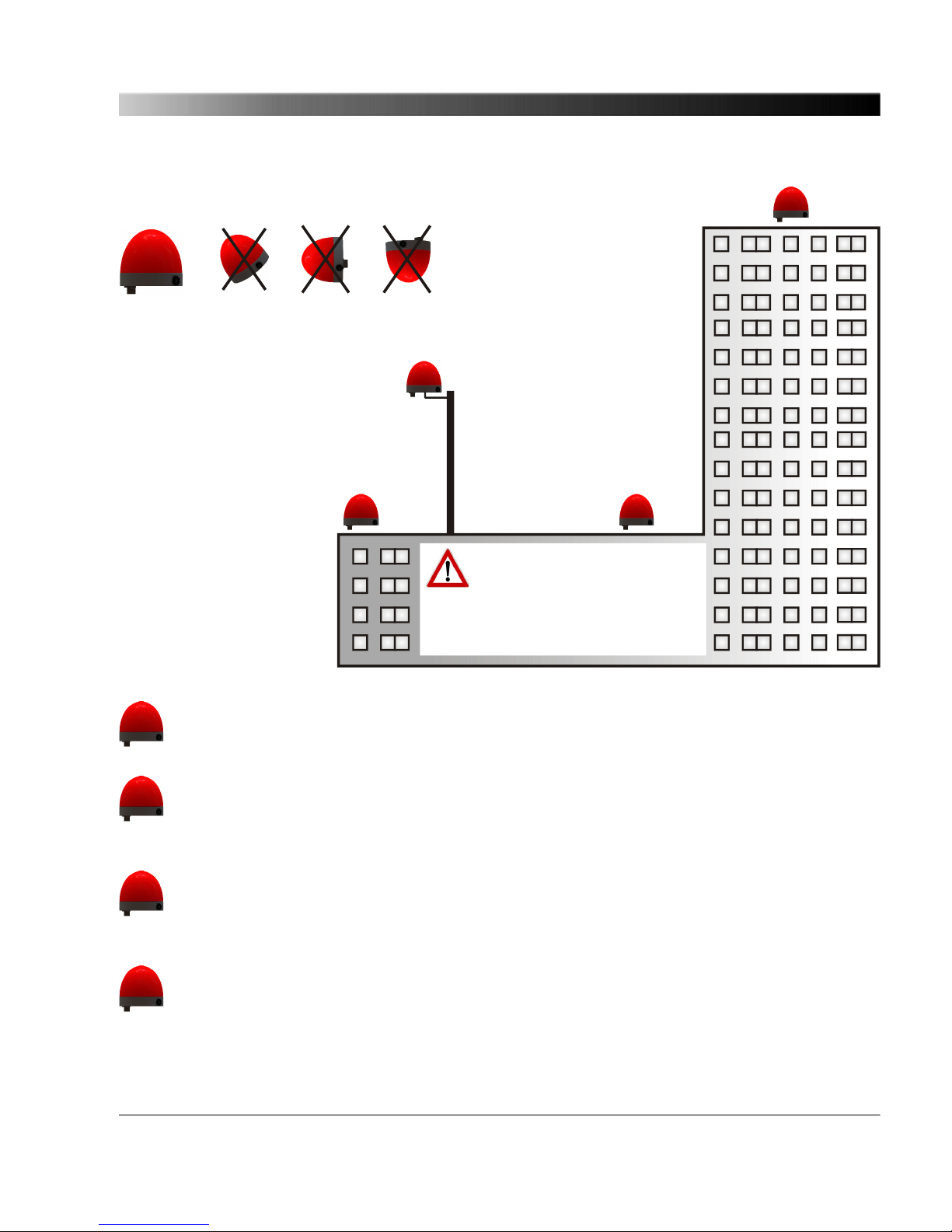
2
BAD
position.
Will not work properly!
BEST
position.
Recommended!
Possible
if no alternative position is
available. Not recommended!
Possible
position.
Mount the OTMC 100 in an upright position
with the protective cap to the top only!
Provide a suitable surge
protection device to the Ethernet
cable leading into the building!
Always observe all relevant
lightning protection regulations!
Use shielded Ethernet cable only!
4
1
3
1
Recommended mounting position with best possible reception of GPS signals.
This mounting position provides direct view to the sky. The view is not hindered by any
objects and the GPS signals are not influenced by any reflections.
2
Possible mounting position providing sufficient reception of GPS signals under most
conditions. This mounting position provides direct view to the sky in a range of nearly 180°.
The view is only partly hindered and there is negligible danger of reflections that could
influence the GPS signals.
3
Possible mounting position if no other mounting position is available. Not recommended!
This mounting position provides direct view to the sky for a range of more than 90° but much
less than 180°. The view to the right is hindered by the taller part of the building and there is
an increased danger of reflections that could influence the GPS signals.
4
Bad mounting position. Do not use!
This mounting position provides direct view to the sky for a range of only 90°. Half the sky is
blocked by the taller part of the building and the reception of GPS signals will be considerably
influenced by reflections. The OTMC 100 will not work properly!
Mounting
15

4.3 Mounting Instructions
There are two possible ways for mounting the OTMC 100. Refer to the subsections below for detailed
mounting instructions.
Mast mounting using the delivered mast
mounting kit.
Temporary mounting using the 1/4" BSW
(British Standard Whitworth) thread for
mounting on a stand, for example.
4.3.1 Mounting Instructions for Mast Mounting
The mast mounting kit delivered with the OTMC 100 contains the following parts:
• 1 mast clamp consisting of 2 clamping jaws and 4 fastening screws M6 x 110 with lock washers
• 2 clamping blocks and 4 fastening screws M6 x 16 with lock washers
• 1 connection pipe 20 x 300 mm
Proceed as follows:
Assemble the mast clamp and attach it to the mast
as shown in the figure.
The mast clamp is suitable for mast diameters of 25
to 70 mm.
Use a tightening torque of 5 Nm for the fastening
screws of the clamping block (1). The tightening
torque for the fastening screws of the mast clamp (2)
depends on the material and diameter of the mast.
1 2
OTMC 100 Series User Manual
16

Attach the clamping block (3) to the base plate of the
OTMC 100 as shown in the figure.
Use a tightening torque of 5 Nm for the fastening
screws.
Exclusively use the two M6 x 16 screws delivered
with the mast mounting kit! Do not use longer
screws! The threaded holes in the base plate are
only 9 mm deep.
3
Insert the connecting pipe (4) to the clamping blocks
on the mast clamp and the OTMC 100 as shown in
the figure.
5
4
Align the OTMC 100 in an upright position as shown
in the figure and tighten both clamping screws (5) of
the clamping blocks evenly with a tightening torque
of 5 Nm.
Assemble the delivered waterproof RJ45 connector
to the Ethernet cable according to the accompanying
assembly instructions and insert it to the RJ45
connector on the base plate of the OTMC 100. Use
suitable cable ties to fasten the Ethernet network
cable to the connecting pipe and the mast.
Always use the waterproof RJ45 Ethernet
connector supplied with the OTMC 100 in
order to maintain the watertightness of the
device. Do not use the OTMC 100 outdoors
without a waterproof connector inserted.
The clamping blocks provide holes for
horizontal and vertical mounting of the
connecting pipe. Therefore, it is also
Mounting
17

possible to mount the OTMC 100 on the
top of a vertically mounted connecting pipe,
as shown in the figure on the right.
4.3.2 Mounting Instructions for Temporary Mounting Using the 1/4" BSW
Thread
Screw the grub screw of the stand into the 1/4" BSW
(British Standard Whitworth) thread (1) on the base
plate of the OTMC 100 and tighten it sufficiently.
The threaded hole in the base plate is 6.5 mm deep.
Make sure not to screw in the grub screw too deep!
Assemble the delivered waterproof RJ45 connector
to the Ethernet cable according to the accompanying
assembly instructions and insert it to the RJ45
connector on the base plate of the OTMC 100. If
necessary, use suitable cable ties to fasten the
Ethernet network cable to the stand.
1
Do not move the OTMC 100 during operation. Changing the position of the OTMC 100
during operation causes time errors.
OTMC 100 Series User Manual
18

5 Connection, Access & Initial Setup
5.1 Connecting the OTMC 100 to an Ethernet Network
Note regarding network switches:
The precise synchronization of clocks via Ethernet networks requires that the propagation
delay times for data packets is constant on the entire network. Network switches that do not
provide transparent clock functionality may introduce jitter and thus influence the propagation
delay. Therefore, the OTMC 100 will only be able to provide highly accurate time
synchronization in networks that that are equipped with network switches providing
transparent clock functionality as specified in IEEE 1588-2008 or that do not have a network
switch at all.
Do not connect conventional RJ45 connectors that are equipped with a locking tab to the
OTMC 100! The locking tab of such connectors cannot be accessed directly anymore after
inserting the plug to the OTMC 100. In this case, a small screwdriver must be used to
carefully unlock the RJ45 connector in the socket. Use the waterproof RJ45 connector
supplied with the OTMC 100 instead or, when using a cable with a conventional RJ45
connector (for test purposes only!), break off the locking tab at the RJ45 connector before
inserting it to the OTMC 100.
The OTMC 100 is supplied with power by Power over Ethernet (PoE) according to IEEE 802.3af. If the
network port the OTMC 100 is connected to does not provide PoE, a PoE injector has to be used as
shown in the figure below.
The OTMC 100 supports Ethernet cable lengths of up to 100 m without the need of repeaters. By
using additional media converters the use of optical Ethernet is possible, which allows much longer
distances. Depending on the used variant it is possible to cover distances up to 2000 m. For further
details, please refer to the user manual of the media converters used.
The OTMC 100 automatically powers up after inserting the RJ45 plug and providing supply voltage to
the OTMC 100. After the device is supplied with voltage, the LED first lights up red for approx. 15 s
during the boot process and then changes to green to indicate operational readiness.
The OTMC 100 is a class 1 powered device (PD) as defined in IEEE 802.3af (power
consumption < 3.84 W). The network port the OTMC 100 is connected to must be able to
supply a class 1 powered device.
CAUTION! Risk of injury or damage due to high voltages caused by lightning stroke.
The local lightning protection regulations and the protection concept of the building and the
electrical installation may require a suitable surge protection device for the Ethernet network
cable leading into the building.
Connection, Access & Initial Setup
19

The following figure shows the general arrangement of the OTMC 100, the surge protection device
and the PoE injector (if necessary).
Ethernet network port
providing PoE
Surge protection device
Ethernet network port
not providing PoE
PoE injector
Surge protection device
Mains
The following figure shows a typical network with one OTMC 100, a network switch providing
transparent clock functionality, and several PTP slaves.
Network switch
(transparent clock)
PTP slavePTP slave PTP slave PTP slave
OTMC 100 Series User Manual
20

5.2 Accessing the OTMC 100 from a Computer
The OTMC 100 automatically powers up after supply voltage is provided via Ethernet (PoE). The LED
lights up green when the device is ready for operation.
After that, a network IP address is assigned automatically in order to connect the device to the
network. If a DHCP server is available in the network, the IP address is assigned by the DHCP server.
If not, the OTMC 100 automatically selects and assigns a link-local IPv4 and IPv6 address by itself.
The OTMC 100 can be configured completely via the Web Interface using a computer. This way, no
manual intervention at the device itself will be required under normal circumstances.
5.2.1 System Requirements
Your computer must fulfill the following requirements to access the OTMC 100 Web Interface:
• Network port configured for operation in the network the OTMC 100 is connected to.
• OMICRON Device Browser installed (see chapter "The OMICRON Device Browser" on page 87).
• Web browser installed (Windows Internet Explorer 8 or higher or Mozilla Firefox 3 or higher).
If you are accessing the OTMC 100 from a Mac or Linux operating system supporting
zeroconf, you can access the web interface of the OTMC 100 by entering
http://<hostname>.local to the address bar of your web browser. The default hostname is
the device serial number. The serial number is available on the type plate on the bottom side
of the OTMC 100 (labeled "SerNo").
5.2.2 Accessing the OTMC 100 Web Interface
Proceed as follows to access the OTMC 100 Web Interface:
1. Connect your computer to the network.
2. If necessary, install the OMICRON Device Browser on your computer. See chapter "The
OMICRON Device Browser" on page 87.
3. Launch the OMICRON Device Browser.
Connection, Access & Initial Setup
21
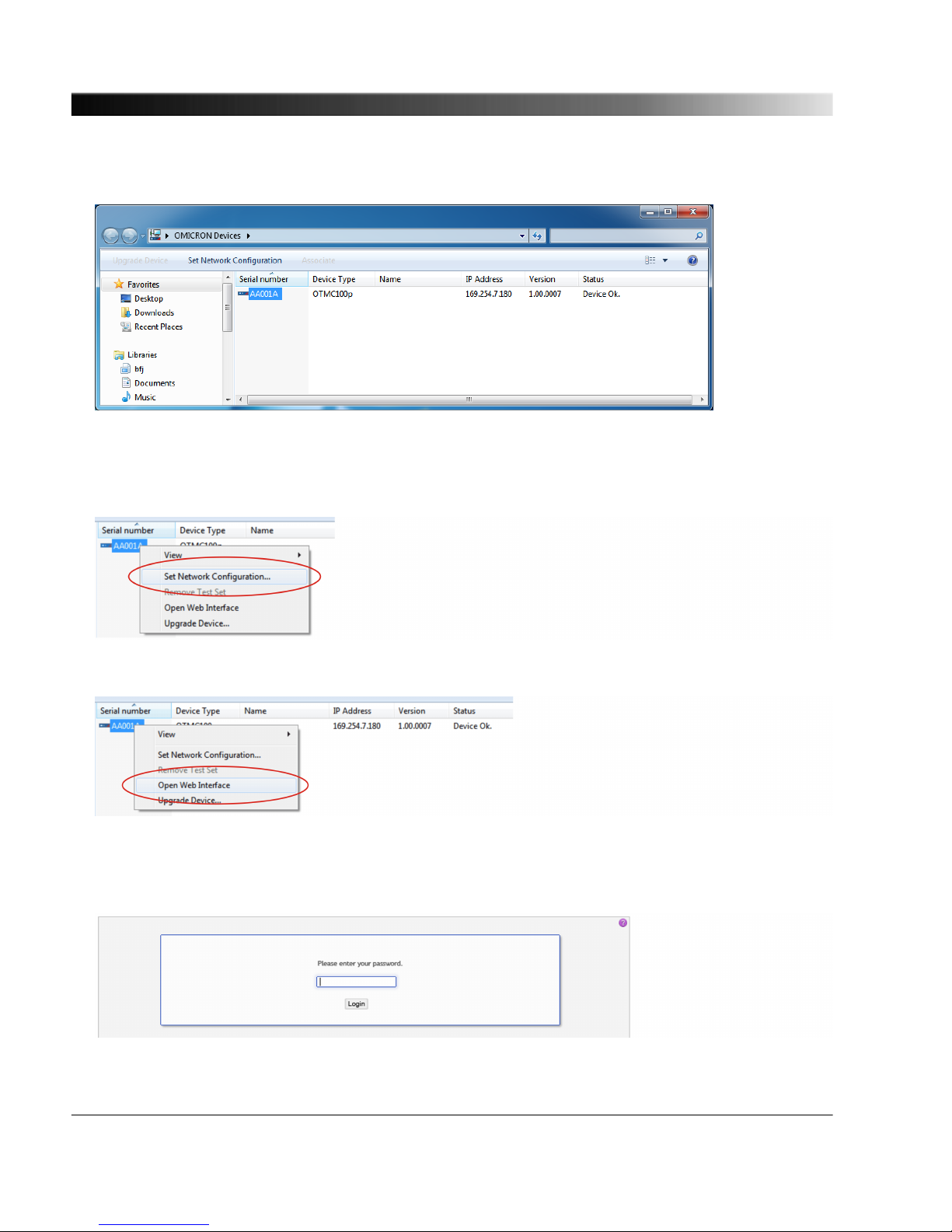
4. The Device Browser will automatically find and display the OTMC 100.
If the IP address configurations of the OTMC 100 and the computer are not compatible, the
respective status is displayed in the Status column. In this case, right-click the OTMC 100 serial
number and select Set Network Configuration to assign a suitable IP address to the OTMC 100.
5. Right-click the OTMC 100 serial number and select Open Web Interface from the context menu.
6. The Web Interface is opened in a web browser.
Password protection is disabled by default. If a password has been defined for the OTMC 100, a
login dialog is displayed. Enter your password and click Login.
OTMC 100 Series User Manual
22

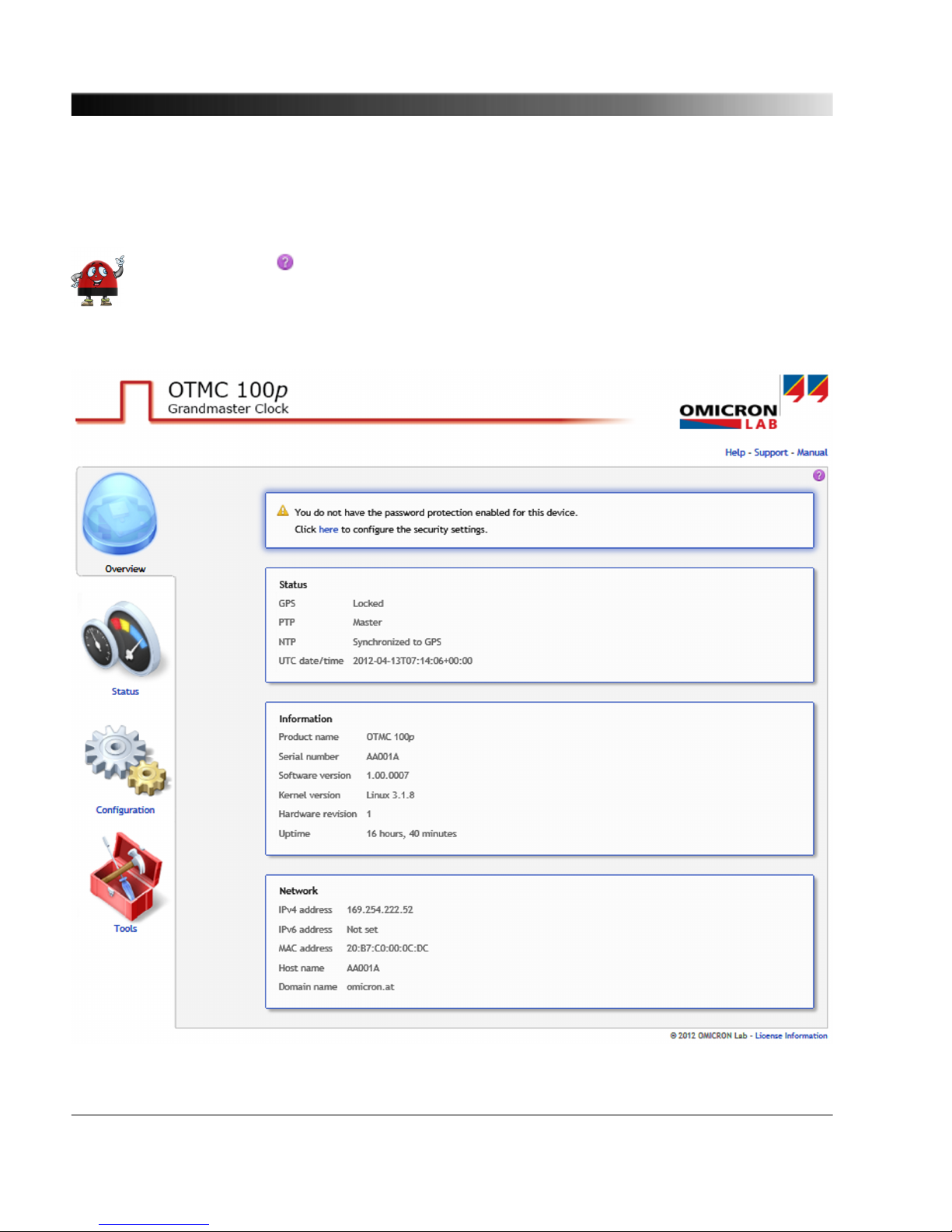
7. The start page of the OTMC 100 Web Interface is displayed.
8. Proceed with section "5.3 Next Steps to Set Up the OTMC 100" on page 24 in order to configure
the OTMC 100 according to your needs.
Connection, Access & Initial Setup
23

5.3 Next Steps to Set Up the OTMC 100
After connecting the OTMC 100 to the network and accessing the device from your computer, you
have to configure the OTMC 100 according to your needs.
See chapter "The OTMC 100 Web Interface" on page 34 or the OTMC 100 online help for a detailed
description of the Web Interface, or section "Operating Procedures Performed via the Web
Interface" on page 27 for a description of the most important operating procedures.
Proceed as follows to set up and configure your OTMC 100. Consult your network administrator if you
do not know the correct settings.
1. Configure the network settings.
Open the Configuration section of the Web Interface and display the Network page (see page
58).
a. Configure the network/IP settings according to the needs of your network. Click the Save All
button to save and apply your settings.
By default, the OTMC 100 will attempt to get an IPv4 address via DHCP and assign
an IPv6 address using the automatic configuration. If no DHCP server is available
for IPv4, the OTMC 100 uses the zeroconf service to automatically assign an IP
address on its own.
OTMC 100 Series User Manual
24

2. Configure the PTP settings.
Display the PTP page of the Configuration section (see page 67). Select your configuration and
click the Save All button to save and apply your settings. The most important PTP settings are:
a. PTP profile (General Settings tab): All PTP devices that should synchronize to each other must
use the same profile.
• Use the Default E2E or Default P2P profile for industrial environments.
Default P2P (peer-to-peer) can only be used if the switches used in the network support and
are configured for operation as peer-to-peer transparent clocks as defined in
IEEE 1588-2008.
Use Default E2E (end-to-end) if standard switches are used in the network and the higher
synchronization error introduced by these switches is acceptable. The Default P2P profile
and the Power Profile according to IEEE C37.238-2011 will not work with those network
switches.
• Use the Power systems profile for power utility environments where all devices are known
to use the Power Profile according to IEEE C37.238-2011 (OTMC 100p only).
b. Operation mode (General Settings tab): Always use the one step operation mode unless there
are devices in the network that do not correctly handle one step master clocks.
c. Domain number (Default Settings tab): All PTP devices that should synchronize to each other
must use the same domain number.
d. Transport (Port Settings tab): Select the transport mechanism according to the needs of your
network. All PTP devices that should synchronize to each other must use the same transport
mechanism.
Connection, Access & Initial Setup
25

3. Secure your OTMC 100 against unauthorized access.
Display the Security page of the Configuration section (see page 62).
a. Password (Access Control tab): Set up a password and select the Web Interface
authentication enabled option. Click the Change button to save and apply your settings. From
now on, entering the password is required to access the OTMC 100.
b. Insecure HTTP (Access Control tab): By default, password transmission to the OTMC 100 is
performed unencrypted. By deselecting the Insecure HTTP enabled option you can force the
use of the encrypted HTTPS protocol and thus protect your password. Click the Change button
to save and apply your settings.
When accessing the OTMC 100 via HTTPS, an "untrusted connection" message
may appear because the OTMC 100 does not have a valid certificate. To avoid
such messages, it is necessary to provide the OTMC 100 with such a certificate.
Please refer to subsection "Generate Certificate tab" in section "Security
Configuration Page" on page 62 for more detailed information.
c. Protocol restrictions: Disabling services that are not required or used for operation will
minimize potential points of attack and thus make the OTMC 100 safer. Click the corresponding
check box to select or deselect an option. Click the Save button to save and apply your settings.
• Usually the OMICRON Device Browser is used to find the OTMC 100 in the network.
However, the OMICRON Device Browser may also be used to change the network
configuration of the OTMC 100. To protect your OTMC 100 against unauthorized or
unintentional configuration changes using the OMICRON Device Browser, deselect the
Allow OMFIND network configuration option.
• If PTP management messages are not used in your network, deselect the Allow PTP SET/
COMMAND management messages option. This will prevent modification of the PTP
settings. Reading the PTP settings is still possible then. In order to completely deactivate the
PTP management interface, deselect the PTP management interface enabled option in the
General Settings tab on the PTP page of the Configuration section (see page 67).
• If you do not want to use the SNMP management interface to configure the OTMC 100,
deselect the Allow SNMPv2c community write access option.
• If you want to prohibit standard user/password authenticated access to the OTMC 100 via
secure shell (SSH), deselect the Allow SSH password login option. When deselected,
access via SSH is only possible via key based authentication. This reduces the risk of
unauthorized access to the OTMC 100 through brute force attacks.
The options in the Protocol Restrictions tab of the Security page just enable or
disable protocol options. In order to completely disable a service, open the
Services tab of the Network configuration page.
OTMC 100 Series User Manual
26

6 Operating the OTMC 100
The following sections describe the most important operating procedures for the OTMC 100. Please
refer to chapter "The OTMC 100 Web Interface" on page 34 or the Web Interface help for a detailed
description of the Web Interface.
6.1 Operating Procedures Performed via the Web Interface
This section describes the most important operating procedures that can be performed via the Web
Interface using a computer.
In order to operate the OTMC 100 via the Web Interface you must access the device from a computer,
e.g., using the OMICRON Device Browser (see section "Accessing and Configuring the OTMC 100
from a Computer" on page 21).
6.1.1 Viewing the GPS, PTP, NTP and Network Status
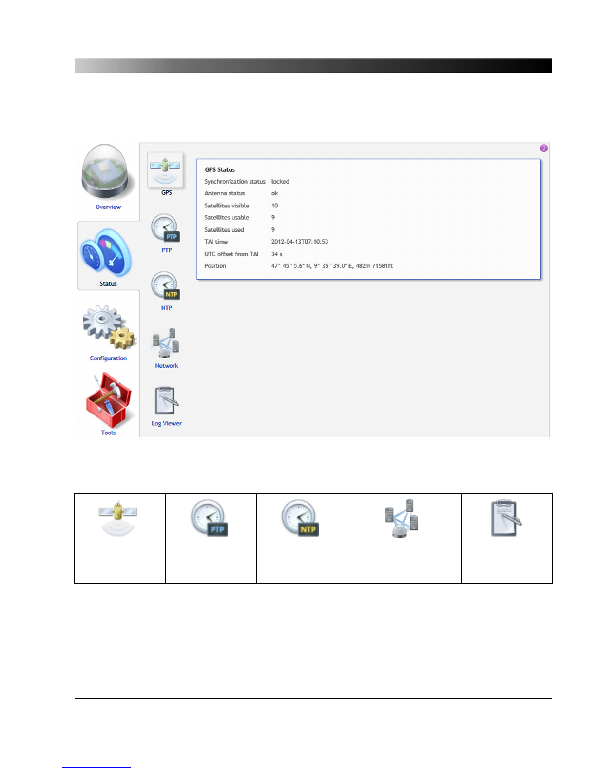
1. The overall GPS, PTP, NTP and network status is displayed in the Overview page of the Web
Interface.
2. To display more detailed status information, click the Status icon in the navigation bar of the Web
Interface.
3. Click the GPS, PTP, NTP or Network icon of the Status section to display the status pages (see
page 39) showing the information.
6.1.2
Defining a Password
If no password is defined for accessing the OTMC 100, a corresponding note is displayed on the
Overview page providing the possibility to directly access the security configuration (see page 62) in
order to enable password protection.
1. Click the Configuration icon in the navigation bar of the Web Interface.
2. Click the Security icon of the Configuration section and display the Access Control tab.
3. Enter your password to the Change password field and repeat it in the Confirm password field.
The password is case sensitive and must have at least 5 characters (letters, figures or
special characters).
4. Select the Web Interface authentication enabled check box to activate password protection.
5. Click the Change button.
6. Your new password is applied to the OTMC 100 and a login dialog appears after a few seconds.
For more information, please refer to "Security Configuration Page" on page 62.
Operating the OTMC 100
27

Perform a factory reset on the device if you forgot your password (see "Operating
Procedures Performed at the Device" on page 31).
6.1.3 Running a Software Update for the OTMC 100
Please note that the OTMC 100 will not deliver time information during a software update.
1. Click the Tools icon in the navigation bar of the Web Interface.
2. Click the Software Upgrade icon.
3. Click the Browse... button to navigate to the software image file and select it.
4. Deselect the Keep settings check box if you want to reset the device configuration to the factory
defaults after the software update. If the check box is selected, the user specific configuration
settings are kept during the software update.
5. Click the Update button to start the software update.
6. The update process may take several minutes. Do not disconnect the OTMC 100 or the computer
during this process.
7. The OTMC 100 automatically restarts after the software update has completed.
If the software update process fails due to any reason, the OTMC 100 enters a recovery
mode on the next power-up. In this mode, the device provides only a rudimentary Web
Interface (similar to the Software Upgrade page) just allowing for the upload of a software
image (see "Operating Procedures Performed at the Device" on page 31).
6.1.4 Performing a Reboot of the OTMC 100
A device reboot can also be performed directly on the device (see "Operating Procedures
Performed at the Device" on page 31).
1. Click the Tools icon in the navigation bar of the Web Interface.
2. Click the Device Control icon.
3. Click the Reboot button next to Reboot device.
4. The OTMC 100 performs a reboot. The device will be ready for operation again after approx. 15 s.
OTMC 100 Series User Manual
28

6.1.5 Performing a Factory Reset (Reset to Factory Defaults)
A factory reset can also be performed directly on the device (see "Operating Procedures
Performed at the Device" on page 31).
Resetting the device to the factory defaults may be necessary if you forgot your password, for
example.
1. Click the Tools icon in the navigation bar of the Web Interface.
2. Click the Device Control icon.
3. Click the Reset button next to Factory reset.
4. The OTMC 100 performs a reboot and resets all configuration settings to the factory defaults. The
device will be ready for operation again after approx. 15 s.
6.1.6 Creating a System Snapshot for Troubleshooting
A system snapshot contains the configuration settings and the log file. It thus provides important
information for the technical support in case of problems.
1. Click the Tools icon in the navigation bar of the Web Interface.
2. Click the Device Control icon.
3. Click the Download button next to System snapshot to download a system snapshot file.
6.1.7
Uploading New Software to the Device in Recovery Mode
Entering the recovery mode manually is only possible using the pushbutton on the device
(see "Operating Procedures Performed at the Device" on page 31).
The recovery mode is entered automatically if a software update performed via the Web Interface fails.
1. In recovery mode the device provides a rudimentary Web Interface solely allowing for the upload of
a software image.
2. Click the Browse... button to navigate to a suitable software image file.
3. Click the Update button to start the software update.
4. The update process may take several minutes. Do not disconnect the OTMC 100 or the computer
during this process.
5. The OTMC 100 automatically restarts after the software has installed completely.
Operating the OTMC 100
29

6.1.8 Assigning an IP Address Manually
The IP address of the OTMC 100 is usually assigned automatically. If a DHCP server is available in
the network, the IP address is assigned by the DHCP server. If not, the OTMC 100 automatically
selects and assigns an IP address on its own.
Assigning an IP address manually is only necessary if the automatic IP address assignment does not
work due to specific characteristics of the network.
1. Click the Configuration icon in the navigation bar of the Web Interface.
2. Click the Network icon of the Configuration section and display the IPv4 tab (or IPv6 if the
network supports IPv6).
3. Select Manual from the list box.
4. Enter the IP address, the Network mask, the Gateway address and the Name server address in
dot-decimal notation (e.g.: 192.168.1.100).
5. Click the Save button to upload and save your settings in the OTMC 100.
See also "Network Configuration Page" on page 58.
6.1.9 Viewing and/or Exporting the System Log File
The log file contains all events logged by the system. Therefore, it may be helpful for the technical
support of OMICRON in case of problems.
Which types of events are actually logged by the system can be selected in the Log & Notifications
configuration (see page 76) .
1. Click the Status icon in the navigation bar of the Web Interface.
2. Click the Log Viewer icon to display the log file.
3. View the messages logged in the file. Error messages are displayed in red, warning messages are
displayed in orange, notice messages are displayed in black. All other messages are displayed in
gray.
4. By clicking Clear View you can clear the display of the Log Viewer page. This does not clear the
log file. Re-opening the Log Viewer page will again display all messages logged in the log file.
5. By clicking Export Log you can export the log file content to a text file (file extension .log).
The log file is cleared with each reboot of the OTMC 100 (see "Performing a reboot of the
OTMC 100" on page 28 or "Performing a reboot of the OTMC 100" on page 31). If the
maximum size of the log file is reached, the system automatically deletes old log file entries
in order to release memory space for new entries.
OTMC 100 Series User Manual
30

6.2 Operating Procedures Performed Directly on the Device
This section describes the operating procedures that can be performed directly at the OTMC 100
using the pushbutton. The pushbutton can be accessed after unscrewing the water-tight membrane
vent. Use a pointed tool such as a ball-pen to press the pushbutton.
Do not forget to reinsert the membrane vent in order to restore watertightness. Tighten the
membrane vent with a tightening torque of 0.6 to 0.8 Nm.
Membrane vent
detached
Pushbutton
LED
Pushbutton
6.2.1 Performing a Reboot of the OTMC 100
A device reboot can also be performed via the Web Interface (see "Performing a reboot of
the OTMC 100" on page 28).
1. Press the pushbutton and release it immediately.
2. The LED goes off for approx. 1 s.
3. The LED lights up red during the boot process.
4. After approx. 15 s the LED changes to green to indicate operational readiness.
Operating the OTMC 100
31

6.2.2 Performing a Factory Reset (Reset to Factory Defaults)
A factory reset can also be performed via the Web Interface (see "Performing a factory
reset" on page 29). Resetting the device to the factory defaults may be necessary if you
forgot your password, for example.
1. Press the pushbutton and keep it pressed.
2. The LED goes off.
3. After approx. 5 s, the LED lights up orange. Keep the button pressed and wait until the LED lights
up red.
4. Release the pushbutton.
5. After approx. 15 s the LED changes to green to indicate operational readiness.
6. The device now has the factory default configuration settings.
6.2.3 Entering the Recovery Mode Manually (and Uploading New Software to
the OTMC 100)
Entering the recovery mode manually is not necessary under normal circumstances since the recovery
mode is entered automatically if a software update performed via the Web Interface fails.
1. Press the pushbutton and keep it pressed.
2. The LED goes off for approx. 5 s.
3. Release the pushbutton as soon as the LED lights up orange.
4. After approx. 20 s the LED flashes green to indicate the recovery mode.
5. Open the OMICRON Device Browser and right-click the OTMC 100 (see "Accessing the
OTMC 100 from a Computer" on page 21). Select the Upgrade Device option from the context
menu. The device provides a rudimentary Web Interface allowing for an upload of a software
image.
OTMC 100 Series User Manual
32

6. Click the Browse... button to navigate to a suitable software image file. The path and file name is
displayed in the field after selecting it in the file open dialog.
7. Click the Update button to start the software update. The update process may take several
minutes. Do not disconnect the OTMC 100 or the computer during this process. The OTMC 100
automatically restarts after the software has installed completely.
Operating the OTMC 100
33
7 The OTMC 100 Web Interface
The Web Interface is used to access and configure the OTMC 100 using a computer.
Click the help icon in the top right corner of a page to display the specific help topic for
this particular page. Click Help in the top right corner of the Web Interface to open the start
page of the help system for the Web Interface.
OTMC 100 Series User Manual
34

Click Manual in the top right corner to open this manual in PDF format.
Click Support in the top right corner to open the contact information page providing OMICRON
contact addresses and information how to contact the technical support of OMICRON in case of
problems.
Click License Information in the bottom right corner to view copyright and license information
regarding open source products used in the OTMC 100 software.
The Web Interface is divided into four main sections. Click an icon in the navigation bar on the left to
access the corresponding pages.
Overview (see page 36)
This page provides an overview of the current settings and states of the
OTMC 100.
Status (see page 39)
The Status pages provide detailed information about the GPS status (e.g.
number of satellites, time and position) and the PTP, NTP and network status.
An additional Log Viewer page shows all events logged in the internal log
file.
Configuration (see page 57)
Use the Configuration pages to view and configure the network, security,
PTP and NTP settings. You can furthermore configure the event logging and
the e-mail notification function of the OTMC 100, and the SNMP settings.
Tools (see page 82)
Use these pages to perform a software upgrade for the OTMC 100 or to
perform a reboot or a factory reset for the device. You can furthermore
download a system snapshot containing important information for the
technical support in case of problems.
The OTMC 100 Web Interface
35

7.1 Overview
The Overview page provides an overview of the current settings and states of the OTMC 100.
If no password is defined for accessing the OTMC 100, a corresponding note is displayed providing
the possibility to directly access the security configuration (see page 62) in order to enable password
protection.
The Overview page displays the following information.
OTMC 100 Series User Manual
36

Status
GPS Displays the current GPS status of the OTMC 100.
Possible states are: Locked, holdover, unlocked.
See "GPS Status Page" on page 40 for more information.
PTP Displays the current PTP status of the OTMC 100.
Possible states are: Master, passive, listening, disabled and faulty.
See "PTP Status Page" on page 42 for more information.
NTP Displays the current NTP status of the OTMC 100.
Possible states are: Synchronized to GPS, synchronized to external server,
nonsynchronous or disabled.
See "NTP Status Page" on page 50 for more information.
UTC date/time Displays the UTC date and time. The local time can be derived from the UTC
time (Universal Time Coordinated) by adding or subtracting hours according to
the specific time zone. For example, UTC plus one hour delivers the Central
European Time CET (two hours during daylight saving time).
Information
Product name Displays the exact product name.
Serial number Displays the serial number of the OTMC 100.
Software version Displays the software version currently installed on the OTMC 100.
Kernel version Displays the kernel version used in the currently installed operating software.
Hardware revision Displays the hardware version of the OTMC 100.
Uptime Displays the time the OTMC 100 is in operation since the last power-up.
Network
IPv4 address Displays the currently assigned IPv4 address of the OTMC 100.
If configured dynamically, the IP address is assigned automatically by a IPv4
DHCP server (if available in the network) or the OTMC 100 itself.
...
The OTMC 100 Web Interface
37

IPv4 address
(cont.)
The IPv4 address can also be set manually by the user.
See also "Network Configuration Page" on page 58.
IPv6 address Displays the currently assigned IPv6 address of the OTMC 100.
If configured dynamically and a IPv6 router is available in the network, the IP
address is assigned automatically.
The IPv6 address can also be set manually by the user.
See also "Network Configuration Page" on page 58.
MAC address Displays the unique MAC address (Media Access Control Address) of the
OTMC 100.
Host name Displays the host name of the OTMC 100. The host name is set to the serial
number by default but can be changed by the user. The serial number is
available on the type plate on the bottom side of the OTMC 100 (labeled
"SerNo").
See also "Network Configuration Page" on page 58.
Domain name Displays the domain name set by the user (e.g.: omicron.at).
See also "Network Configuration Page" on page 58.
OTMC 100 Series User Manual
38
7.2 Status
The following status pages are available:
GPS
(see page 40)
PTP
(see page 42)
NTP
(see page 50)
Network
(see page 53)
Log Viewer
(see page 55)
The OTMC 100 Web Interface
39
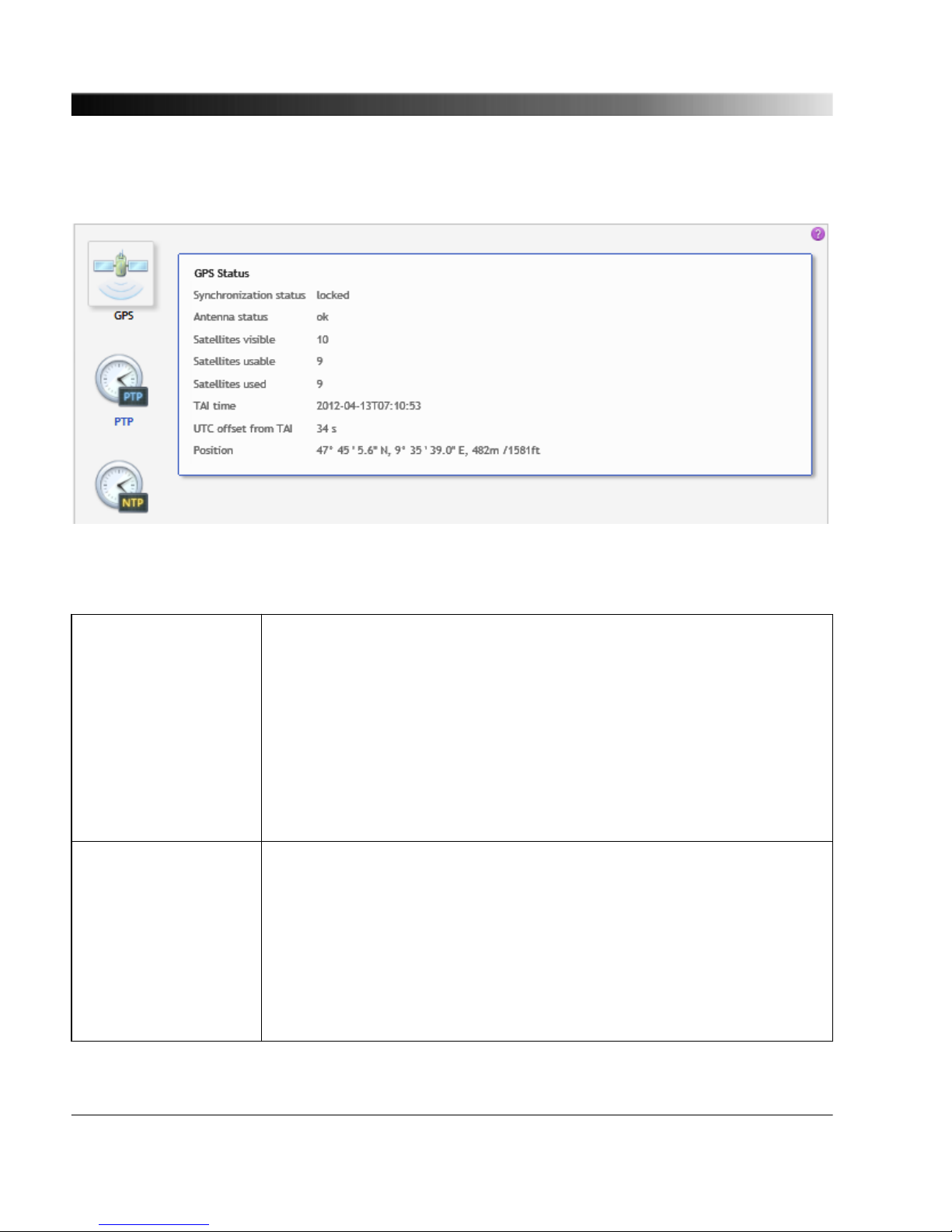
7.2.1 GPS Status Page
The GPS status page displays the following information:
Synchronization status Displays the current GPS status of the OTMC 100:
Locked: The internal clock is synchronized and controlled by GPS
satellites. The OTMC 100 is able to provide GPS synchronized time.
Holdover: The OTMC 100 will enter this state if was in the locked state
before and then temporarily looses time synchronization with GPS
satellites. In the holdover state, the device is still able to provide time
information with possibly reduced accuracy for a certain time.
Unlocked: The internal clock is not synchronized with GPS satellites. The
OTMC 100 is not able to provide time information.
Antenna status Displays the current GPS antenna status of the OTMC 100.
Ok: No antenna problem detected. Note that this status does not deliver
any information about GPS reception. It is also possible that the antenna is
defective but the defect could not be detected by the GPS receiver.
Open circuit or Overcurrent: Hardware error. The internal GPS antenna
is defective. Contact the technical support of OMICRON and send the
OTMC 100 to OMICRON to be repaired.
...
OTMC 100 Series User Manual
40

Antenna status (cont.) Unknown: The antenna status cannot be determined. Please check the
log file and try to reboot the device (see "Performing a reboot of the
OTMC 100" on page 28). If this does not help, contact the OMICRON
support.
See chapter "Contact Information / Technical Support" on page 94 for
OMICRON addresses and information how to contact the technical
support of OMICRON.
Satellites visible Displays the number of satellites the OTMC 100 can "see" in the sky.
Satellites usable Displays the number of satellites from which the OTMC 100 can receive
signals with sufficient quality.
The OTMC 100 requires at least 4 "useable" satellites.
Satellites used Displays the number of satellites actually used by the OTMC 100 for time
synchronization and position determination.
TAI time Displays the date and time according to the International Atomic Time
(TAI). TAI is the basis for UTC with the difference that UTC is occasionally
adjusted by adding a leap second (in order to keep the difference between
UTC and UT1 lower than 0.9 seconds).
UTC offset from TAI Displays the difference of UTC with regard to TAI.
Position Displays the position coordinates (latitude and longitude) in degrees,
minutes and seconds, and the height in meters and feet.
The OTMC 100 Web Interface
41

7.2.2 PTP Status Page
The information in the PTP status page is displayed in four tabs.
7.2.2.1
Port tab
The Port tab displays information on the current state and configuration of the PTP port of the
OTMC 100. The data listed here correspond to the Port Dataset specified in IEEE 1588-2008, clause
8.2.5.
Port state Displays the current PTP state of the network port of the OTMC 100.
Possible states are: Master, passive, listening, disabled, faulty.
Master: The OTMC 100 is the best master clock in the network
(according to the BMCA) and is thus used as time reference (PTP
grandmaster clock).
Passive: Another PTP clock in the network is the best master clock
according to the BMCA (e.g., has a higher priority or provides more
accurate time). Therefore, the other clock is used as time reference in
the network.
...
OTMC 100 Series User Manual
42

Port state (cont.) Listening: After initialization the OTMC 100 is listening for messages
from other PTP master clocks in the network before it becomes either
master or passive.
Disabled: The PTP state machine of the OTMC 100 has been disabled
via the management interface.
Faulty: The OTMC 100 detected a fault condition. Further details about
the error can be found in the log file.
See IEEE 1588-2008, clause 9.2.5 for more detailed information.
Delay mechanism Displays which PTP delay mechanism is currently used by the
OTMC 100. The value of this parameter may either be E2E (end-toend) or P2P (peer-to-peer). The PTP delay mechanism used depends
on the PTP profile selected in the PTP configuration (see page 67) .
Sync interval [s] Displays the mean synchronization interval for multicast messages
(interval between successive Sync messages).
This parameter is set in the PTP configuration (see page 67) .
Sync Interval = 2
Log sync interval
seconds, see IEEE 1588-2008, clause
8.2.5.4.3.
Announce interval [s] Displays the mean time interval between successive Announce
messages. See IEEE 1588-2008, clause 8.2.5.4.1.
This parameter is set in the PTP configuration (see page 67) .
Announce interval = 2
Log announce interval
seconds.
Announce receipt timeout Displays the number of "Announce Interval" intervals that have to pass
without the receipt of an Announce message before an
ANNOUNCE_RECEIPT_TIMEOUT_EXPIRES event occurs. See
IEEE 1588-2008, clause 8.2.5.4.2.
This parameter is set in the PTP configuration (see page 67) .
Minimum pdelay request
interval [s]
Displays the minimum permitted mean time interval between
successive Pdelay_Req messages. See "logMinPdelayReqInterval" in
IEEE 1588-2008. Only available for Default P2P profile and Power
Profile!
This parameter is set in the PTP configuration (see page 67) .
Minimum pdelay request interval = 2
Log min pdelay request interval
seconds, see
IEEE 1588-2008, clause 8.2.5.4.5.
The OTMC 100 Web Interface
43

Minimum delay request
interval [s]
Displays the minimum permitted mean time interval between
successive Delay_Req messages. This value is determined and
advertised by a master clock based on the ability of the master. Only
available for PTP profile "Default E2E"!
This parameter is set in the PTP configuration (see page 67) .
Minimum delay request interval = 2
Log min delay request interval
seconds, see
IEEE 1588-2008, clause 8.2.5.3.2.
Peer mean path delay [ns] Displays the estimate of the current one-way propagation delay on the
link computed using the peer delay mechanism. If the delay
mechanism is E2E, this value is zero. See IEEE 1588-2008, clause
8.2.5.3.3.
Delay asymmetry [ns] Displays the asymmetry delay. The asymmetry delay is defined to be
positive when the master-to-slave or responder-to-requestor
propagation time is longer than the slave-to-master or requestor-toresponder propagation time. See IEEE 1588-2008, clause 7.4.2.
Time (master -> slave) = meanPathDelay + delayAsymmetry
Time (slave -> master) = meanPathDelay - delayAsymmetry
Profile id Displays the profile identity. The profile identity identifies the PTP
profile implemented by the port indicated by the
targetPortIdentity.portNumber member of the field.
See IEEE 1588-2008, clause 15.5.3.1.2.10.
Network protocol Displays the network protocol selected for the Transport parameter in
the PTP configuration (see page 67) .
Possible values are "UDP_IP_V4" (transport via UDP packets over
IPv4), "UDP_IP_V6" (transport of the PTP packets via UDP over IPv6),
and IEEE_802_3 (transport via Ethernet packets according to
IEEE 802.3).
Vlan ID Displays the Vlan ID. The Power Profile according to
IEEE C37.238-2011 requires an IEEE 802.1Q VLAN tag. This value
represents the VID (VLAN Identifier) field (12 bits) within the TCI (Tag
Control Identifier). See IEEE C37.238-2011, clause 5.6. Only available
for Power Profile (OTMC 100p only).
This parameter is set in the PTP configuration (see page 67) .
OTMC 100 Series User Manual
44

Vlan priority Displays the Vlan priority. The Power Profile according to
IEEE C37.238-2011 requires an IEEE 802.1Q VLAN tag. This value
represents the PCP (Priority Code Point) field (3 bits) within the TCI
(Tag Control Identifier). See IEEE C37.238-2011, clause 5.6. Only
available for Power Profile (OTMC 100p only).
This parameter is set in the PTP configuration (see page 67) .
7.2.2.2 Default tab
The Default tab displays the current configuration/state of the internal PTP clock of the OTMC 100.
When the OTMC 100 is in the master state, the slave clocks in the network/domain in which the
OTMC 100 participates are synchronized to this clock. The data listed here correspond to the Default
Dataset specified in IEEE 1588-2008, clause 8.2.1.
Two step Indicates whether the OTMC 100 is operating as a two step clock (true)
or as a one step clock (false), see IEEE 1588-2008, clauses 7.3.8.3,
8.2.1.2.1 and 13.3.2.6.
This parameter is set in the PTP configuration (see page 67) .
Clock identity Displays the clock identity. IEEE 1588-2008, clause 7.5.2.2, requires that
each clock in a PTP network has a unique clock identifier. This identifier
is an 8-octet array. The OTMC 100 automatically sets the clock identity to
a unique value based on the device's MAC address according to
IEEE 1588-2008, clause 7.5.2.2.2.
Clock class Displays the current clock class of the OTMC 100 (see IEEE 1588-2008,
clause 7.6.2.4). The clock class is broadcast in the corresponding PTP
data packets. The value of the clock class parameter is automatically set
by the OTMC 100 depending on the source of time that is currently
available:
PRIMARY_REF_PTP (6)
The clock of the OTMC 100 is locked to a primary reference time source,
i.e., to the GPS system.
PRIMARY_REF_PTP_HOLDOVER (7)
The clock was previously locked to GPS time but has lost GPS reception.
The internal oscillator of the OTMC 100 is used as the source of time and
provides time with the accuracy given by the Clock accuracy parameter.
NOT_IN_SPEC_PTP_A (52)
The clock is not locked to GPS time and is not within its holdover
specification.
The OTMC 100 Web Interface
45

Clock accuracy Displays the current accuracy of the OTMC 100's internal clock with
regard to TAI. See IEEE 1588-2008, clause 7.6.2.5 for details. This
parameter is determined automatically by the OTMC 100, considering the
quality of the current GPS reception.
Clock variance Displays the clock variance. The clock variance parameter is set to the
PTP variance value specified by IEEE 1588-2008, clause 7.6.3. This
parameter gives a measure for the stability of the internal oscillator of the
OTMC 100 and is used in the Best Master Clock Algorithm (BMCA) of the
PTP protocol. The Clock variance of the OTMC 100 is set to a constant
value that was determined from laboratory observations.
Priority 1
Priority 2
Displays the priority values of the OTMC 100. To each PTP master clock,
two priority values (Priority 1 and Priority 2) may be assigned by the user.
If more than one PTP grandmaster clock is available in the network, a
clock with a lower Priority 1 value will always be the preferred master
clock over a clock with a higher Priority 1 value (see IEEE 1588-2008,
clause 6.6.2.3). A value in the range from 0 to 255 may be assigned to
the Priority 1 parameter (see IEEE 1588-2008, clause 7.6.2.2).
The Priority 2 parameter (see IEEE 1588-2008, clause 7.6.2.3) is used if
several devices have the same Priority 1 parameter value and the same
clock quality (class, accuracy and variance). The Priority 2 parameter
thus allows a finer grained ordering among otherwise equivalent clocks
(see IEEE 1588-2008, clause 6.6.2.3). Lower values take precedence.
These parameters are set in the PTP configuration (see page 67) .
Domain number Displays the domain number of the OTMC 100. The domain number
specifies the PTP domain (see IEEE 1588-2008, clause 7.1) in which the
OTMC 100 participates. All clocks in a network that shall be synchronized
to each other must participate in the same PTP domain, i.e., have the
Domain number parameter set to the same value.
This parameter is set in the PTP configuration (see page 67) .
Slave only Displays whether the clock is a slave-only clock (true) or not (false). See
IEEE 1588-2008, clause 8.2.1.4.4.
IEEE C37.238
grandmaster ID
Displays the grandmaster identity of the OTMC 100 to be transmitted in
IEEE C37.238 TLV. By sending this ID, the OTMC 100 identifies itself as
a valid power profile grandmaster. A power profile slave will ignore all
masters that do not provide a setting for this field. Only available for
Power Profile (OTMC 100p only).
This parameter is set in the PTP configuration (see page 67) .
OTMC 100 Series User Manual
46

Local time inaccuracy
[ns]
Displays the maximum time inaccuracy in ns that the device contributes
to the network time inaccuracy. See IEEE C37.238-2011, clause 5.13.
Only available for Power Profile (OTMC 100p only).
This parameter is set in the PTP configuration (see page 67) .
Network time inaccuracy
[ns]
Displays the network time inaccuracy in ns to be transmitted in
IEEE C37.238 TLV. See IEEE C37.238-2011, clause 5.13. Only available
for Power Profile (OTMC 100p only).
This parameter is set in the PTP configuration (see page 67) .
7.2.2.3 Parent tab
The Parent tab displays information about the current grandmaster clock of the network/domain in
which the OTMC 100 operates. If the OTMC 100 is currently the master of the network or domain, the
values given here are identical to the values in the Default tab (see page 45) . Otherwise, information
about the respective grandmaster clock is given here. The data corresponds to the Parent Dataset
specified by IEEE 1588-2008, clause 8.2.3.
Port identity Displays the port identity. This parameter states the port identity of the
OTMC 100 as defined by IEEE 1588-2008, clause 7.5.2, in the format
portNumber@clockIdentity.
GM identity Displays the grandmaster identity. This is the unique identifier of the
clock that is currently the grandmaster clock of the network or domain
in which the OTMC 100 participates.
GM clock class Displays the grandmaster clock class. This parameter specifies the
current clock class of the current grandmaster clock in the network or
domain (see IEEE 1588-2008, clause 7.6.2.4). The value of the GM
clock class parameter is automatically set by the current grandmaster
clock depending on the source of time that is currently available.
GM clock accuracy Displays the current accuracy of the internal clock of the current
grandmaster clock with regard to TAI. See IEEE 1588-2008, clause
7.6.2.5 for details.
GM clock variance Displays the grandmaster clock variance. The GM clock variance
parameter is set to the PTP variance value specified by IEEE
1588-2008, clause 7.6.3. This parameter gives a measure for the
stability of the internal oscillator of the current grandmaster clock and is
used in the Best Master Clock Algorithm (BMCA) of the PTP protocol.
The OTMC 100 Web Interface
47

GM priority 1
GM priority 2
Displays the priority 1 and 2 of the current grandmaster clock. If more
than one PTP grandmaster clock is available in the network, a clock
with a lower Priority 1 value will always be the preferred master clock
over a clock with a higher Priority 1 value (see IEEE 1588-2008, clause
6.6.2.3). A value in the range from 0 to 255 may be assigned to the
Priority 1 parameter (see IEEE 1588-2008, clause 7.6.2.2).
The Priority 2 parameter (see IEEE 1588-2008, clause 7.6.2.3) is used
if several devices have the same Priority 1 parameter value and the
same clock quality (class, accuracy and variance). The Priority 2
parameter thus allows a finer grained ordering among otherwise
equivalent clocks (see IEEE 1588-2008, clause 6.6.2.3). Lower values
take precedence.
IEEE C37.238
grandmaster ID
Displays the grandmaster identity announced in IEEE C37.238 TLV. By
sending this ID, the current grandmaster clock identifies itself as a valid
power profile grandmaster. A power profile slave will ignore all masters
that do not provide a setting for this field. Only available for Power
Profile (OTMC 100p only).
GM time inaccuracy [ns] Displays the maximum time inaccuracy in ns that the current
grandmaster clock contributes to the network time inaccuracy. See
IEEE C37.238-2011, clause 5.13. Only available for Power Profile
(OTMC 100p only).
Network time inaccuracy
[ns]
Displays the network time inaccuracy of the current grandmaster clock
in ns announced in IEEE C37.238 TLV. See IEEE C37.238-2011,
clause 5.13. Only available for Power Profile (OTMC 100p only).
OTMC 100 Series User Manual
48

7.2.2.4 Time tab
The Time tab displays parameters for the time that is currently distributed in the PTP network or
domain in which the OTMC 100 participates (e.g., epoch related parameters like UTC offset or leap
second information), and parameters of the time source currently used. If the OTMC 100 is the current
grandmaster of the network, the data in this tab represent its own time source. If the OTMC 100 is in
passive state, this tab lists the parameter values of the current grandmaster clock in the network or
domain. The data listed here represents the Time Properties Data set specified in IEEE 1588-2008,
clause 8.2.4.
UTC offset Displays the UTC offset. In PTP systems whose epoch is the PTP
epoch, the value is the offset between TAI and UTC in seconds;
otherwise the value has no meaning. See IEEE 1588-2008, clause
8.2.4.2.
UTC offset valid True indicates that the value of the UTC offset parameter is valid.
Otherwise false. See IEEE 1588-2008, clause 8.2.4.3.
Leap 59
Leap 61
Displays the boolean values that are used to notify the clocks in the
network or domain that a UTC leap second is pending.
Leap 59 = True means that the last minute of the current UTC day
contains only 59 seconds (see IEEE 1588-2008, clause 8.2.4.4).
Leap 61 = True means that the last minute of the current UTC day
contains 61 seconds (see IEEE 1588-2008, clause 8.2.4.5).
Time traceable True indicates that the time currently distributed in the network or
domain is traceable to a primary reference, e.g., to GPS (see
IEEE 1588-2008, clause 8.2.4.6)
Frequency traceable True indicates that the frequency determining the timescale
currently distributed in the network or domain is traceable to a
primary reference, e.g., to GPS (see IEEE 1588-2008, clause
8.2.4.7).
PTP time scale True indicates that the timescale distributed in the network or
domain is the PTP timescale, i.e., TAI time. False if an arbitrary
timescale is used. See IEEE 1588-2008, clause 8.2.4.8.
Example: GPS (0x20) means that the current grandmaster clock is
synchronized to a satellite system like GPS.
Time source Displays the source of time that is used by the current grandmaster
clock (see IEEE 1588-2008, clause 8.2.4.9). Possible values for this
parameter are listed in IEEE 1588-2008, clause 7.6.2.6.
The OTMC 100 Web Interface
49
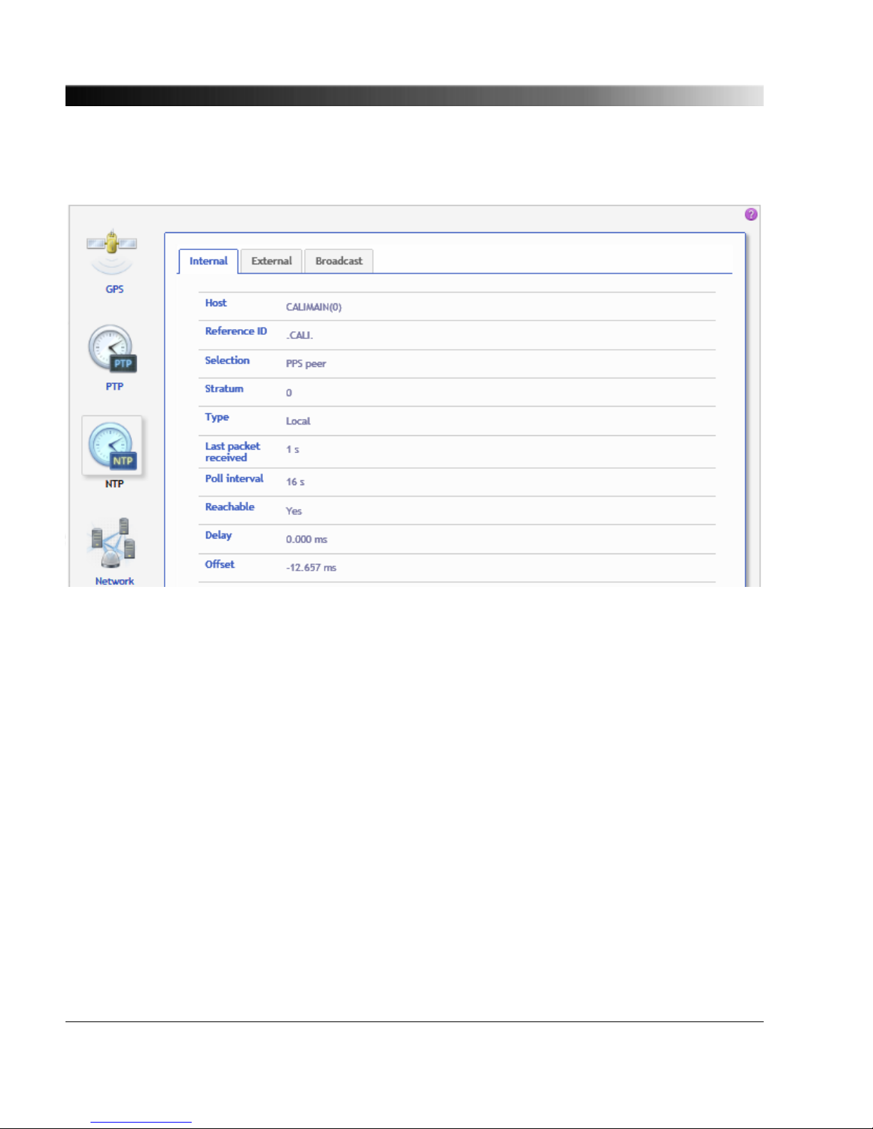
7.2.3 NTP Status Page
The NTP status page displays status information for the local driver (Internal tab) as well as for the
external servers and the broadcast/multicast servers configured in the NTP configuration (see
page 73) (External and Broadcast tabs). Refer to the respective subsection below.
OTMC 100 Series User Manual
50

7.2.3.1 Internal tab
The Internal tab displays the current status information of the local driver. The local driver sets the
system time to the PTP time if the GPS synchronization status is "locked" and the UTC offset is valid.
Afterwards the system time is steered with a 1-PPS from the PTP clock.
Host Displays the host name (or IP number) of the peer.
Reference ID Displays the association ID or kiss code (kiss-o'-death).
Code
ACST
AUTH
AUTO
BCST
CALI
CRYPT
DENY
INIT
MCST
RATE
TIME
STEP
XFAC
Description
Manycast server
Authentication error
Autokey sequence error
Broadcast server
Local GPS time server
Autokey protocol error
Access denied by server
Association initialized
Multicast server
Rate exceeded
Association timeout
Step time change
Interface has changed
Selection Displays the current selection status of the peer.
NTPQ
' '
'x'
'.'
'-'
'+'
'#'
'*'
'o'
Description
Discarded (not valid)
Discarded (intersection)
Discarded (table overflow)
Discarded (cluster)
Include (combine)
Backup
System peer
PPS peer
Stratum Displays the stratum of the peer (0 - 15).
Type Displays the type information of the peer.
NTPQ
'u'
'b'
'l'
Description
Unicast
Broadcast/multicast
Local
The OTMC 100 Web Interface
51

Last packet received Displays the time in seconds when the last packet was received.
Poll interval Displays the poll interval in seconds.
Reachable Displays whether the peer is reachable or not ("yes" or "no").
Delay Displays the round trip time of the query (in ms).
Offset Displays the difference (in ms) between the reference time and the system
clock.
Jitter Displays the magnitude (in ms) of the jitter between several time queries.
7.2.3.2 External tab
The External tab displays the status information for the external servers configured in the NTP
configuration (see page 73) .
Please refer to the Internal tab section (see page 51) for a detailed description of the displayed
information.
7.2.3.3 Broadcast tab
The Broadcast tab displays the Host, the Reference ID, the Stratum and the Poll interval for each
broadcast/multicast server configured in the NTP configuration (see page 73) .
Please refer to the Internal tab section (see page 51) for a detailed description of the displayed
information.
OTMC 100 Series User Manual
52

7.2.4 Network Status Page
The Network status page shows detailed network settings of the OTMC 100 in three tabs. For
information how to configure the network settings, see "Network Configuration Page" on page 58.
7.2.4.1
General tab
The General tab displays the general configuration settings of the OTMC 100.
MAC address Displays the unique MAC address (Media Access Control Address) of the
OTMC 100.
Host name Displays the host name of the OTMC 100. The host name is set to the serial
number by default but can be changed by the user in the Network configuration
(see page 58) . The serial number is available on the type plate on the bottom
side of the OTMC 100 (labeled "SerNo").
Domain name Displays the domain name set by the user in the Network configuration (see
page 58) (e.g.: omicron.at).
The OTMC 100 Web Interface
53

7.2.4.2 IPv4 tab
The IPv4 tab displays the IPv4 specific configuration settings of the OTMC 100. The IPv4
configuration is set in the Network configuration (see page 58) .
Configuration Displays the configuration method selected for IPv4.
Disabled: IPv4 is switched off.
Static: The IP address was assigned manually by the user.
DHCP: The IP address was assigned automtically by a DHCP server.
IP address Displays the currently assigned IPv4 address of the OTMC 100 (e.g.:
192.168.1.100).
Network mask Displays the network mask in dot-decimal notation (e.g.: 255.255.255.0).
Gateway If set, this parameter displays the gateway address in dot-decimal notation
(e.g.: 192.168.1.1).
Name server 1
Name server 2
If set, these parameters display the address of the first and second name
server selected in dot-decimal notation (e.g.: 192.168.1.50).
7.2.4.3 IPv6 tab
The IPv6 tab displays the IPv6 specific configuration settings of the OTMC 100. The IPv6
configuration is set in the Network configuration (see page 58) .
Configuration Displays the configuration method selected for IPv6.
Disabled: IPv6 is switched off.
Static: The IP address was assigned manually by the user.
Autoconf: The IP address was assigned automatically using the Stateless
Address Autoconfiguration (SLAAC).
IP address Displays the currently assigned IPv6 address of the OTMC 100.
Network mask Displays the network mask in dot-decimal notation.
Gateway If set, this parameter displays the gateway address in hexadecimal notation.
Name server 1
Name server 2
If set, these parameters display the address of the first and second name
server in hexadecimal notation.
Link local address
Link local mask
Displays the link local address and the respective mask automatically assigned
by the Stateless Address Autoconfiguration (SLAAC) if the Autoconf
configuration is selected in the IPv6 Network configuration (see page 58) .
OTMC 100 Series User Manual
54
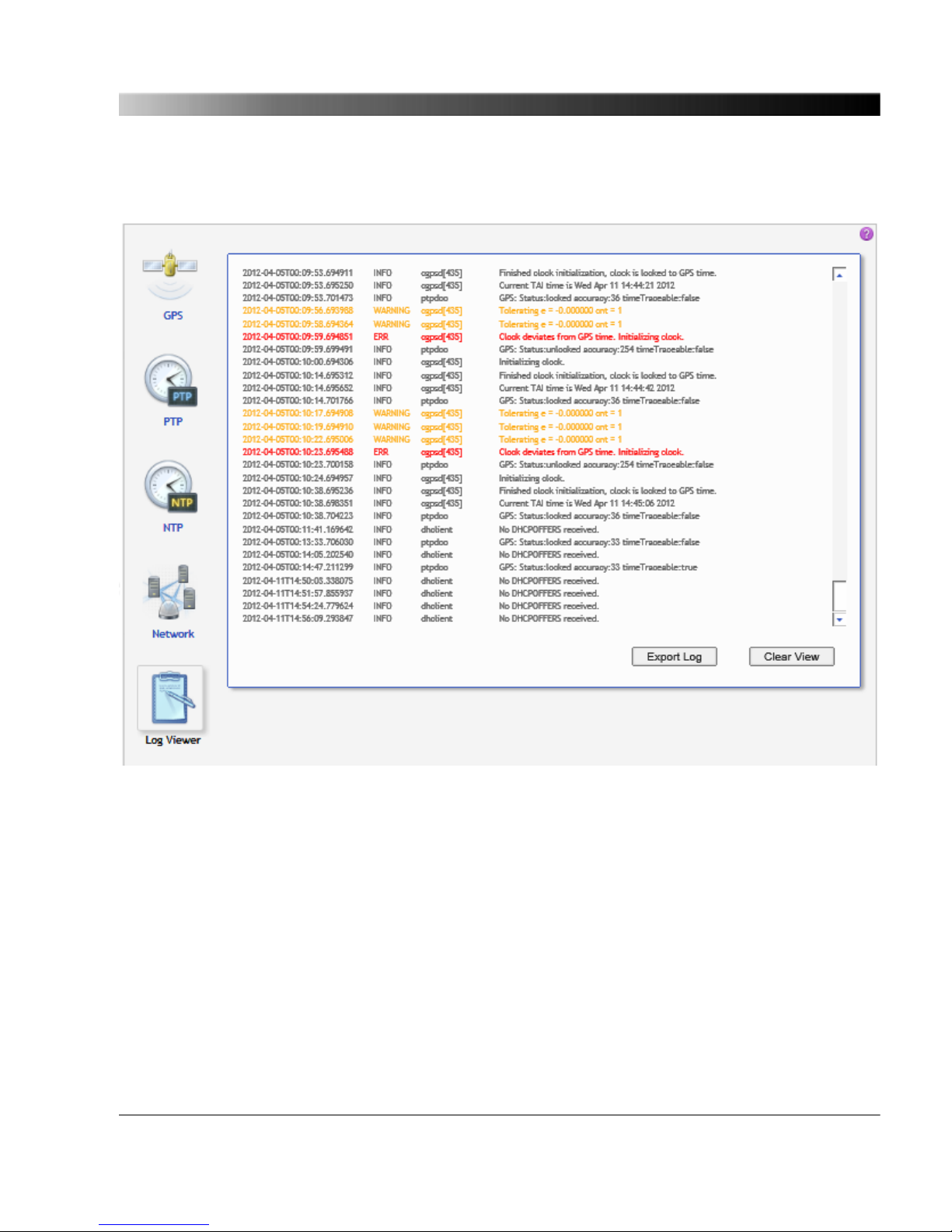
7.2.5 Log Viewer Page
The Log Viewer page shows all events logged in the internal log file.
Which types of events are actually logged by the system can be selected in the Log & Notification
configuration (see page 76) .
ERR
Error messages are displayed in red.
WARNING
Warning messages are displayed in orange.
NOTICE
Notice messages are displayed in black.
INFO
All other messages (debug messages, information, etc.) are displayed in gray.
Click Clear View to delete the messages displayed in the Log Viewer window. This does not clear the
log file. Re-opening the Log Viewer will again display all messages logged in the log file.
Click Export Log to export the log file content to a text file (file extension .log).
The OTMC 100 Web Interface
55

The log file is cleared with each reboot of the OTMC 100 (see "Performing a reboot of the
OTMC 100" on page 28 or "Performing a reboot of the OTMC 100" on page 31). If the
maximum size of the log file is reached, the system automatically deletes old log file entries
in order to release memory space for new entries.
OTMC 100 Series User Manual
56

7.3 Configuration
The following configuration pages are available.
Network (see page 58)
Security (see page 62) PTP (see page 67)
NTP (see page 73) Log & Notifications
(see page 76)
SNMP (see page 80)
The OTMC 100 Web Interface
57
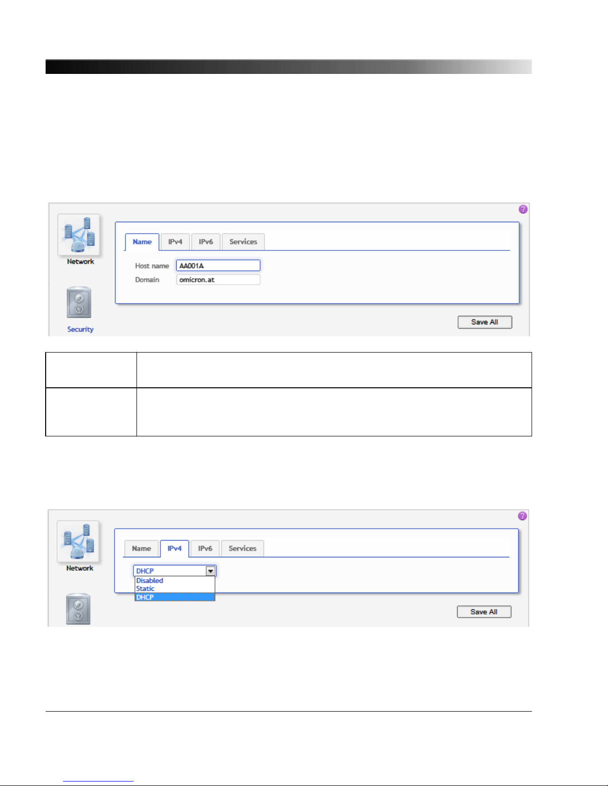
7.3.1 Network Configuration Page
Select the corresponding tab to specify your network configuration settings. Click the Save All button
to save and apply your network configuration specified in the individual tabs to the OTMC 100.
7.3.1.1 Name tab
Host name Host name (device name) of the OTMC 100. The host name is set to the serial
number by default but can be changed by the user.
Domain Domain name. If a DHCP server is available in the network, the OTMC 100
receives the domain name from the DHCP server. The domain name can also be
set manually by the user (e.g.: omicron.at).
7.3.1.2 IPv4 tab
Select the IPv4 configuration according to your needs:
OTMC 100 Series User Manual
58
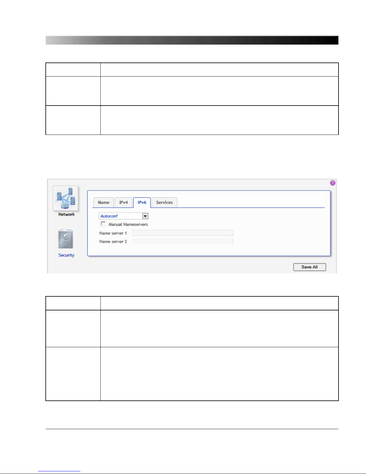
Disabled IPv4 is switched off.
Static Select Static to set the IP address manually. The page then displays fields for
entering the IP address, the Network mask, the Gateway address and the
Name server address in dot-decimal notation (e.g.: 192.168.1.100).
DHCP The IP address is assigned automatically by a IPv4 DHCP server (if available in
the network) or the OTMC 100 itself. The IP address assigned is displayed in the
Overview page (see page 36) .
7.3.1.3 IPv6 tab
Select the IPv6 configuration according to your needs:
Disabled IPv6 is switched off.
Static Select Static to set the IP address manually. The page then displays fields for
entering the IP address, the Gateway address and the Name server address in
hexadecimal notation (e.g.: 2607:f0d0:2001:a::10), and the Network mask in
decimal notation.
Autoconf The IP address is assigned automatically using the Stateless Address
Autoconfiguration (SLAAC). The IP address assigned is displayed in the
Overview page (see page 36) .
Additionally, the user has the option to manually specify DNS servers by
selecting the Manual Nameservers option and entering DNS server addresses
to the Name server fields (in hexadecimal notation, e.g.: 2607:f0d0:2001:a::10).
The OTMC 100 Web Interface
59

7.3.1.4 Services tab
Use this tab to enable or disable individual services and processes running on the OTMC 100 system.
All services are enabled by default. Disabling services that are not used or required for your
specific application will enhance the device security.
Precision Time Protocol
(PTP)
Select the checkbox to enable PTP support (propagation of time
information via PTP in the network).
Network Time Protocol (NTP) Select the checkbox to enable NTP support (propagation of time
information via NTP in the network).
Internet Time Service /
Daytime Service
Select the checkbox to enable Time/Daytime support (propagation
of time information via the Time and Daytime protocol).
Omicron OMFIND Select the checkbox to enable the Omicron OMFIND service. This
service is used by the OMICRON Device Browser to automatically
detect OMICRON devices in the network.
Zeroconf Select the checkbox to enable detection of OTMC 100 devices in
the network by clients that are able to handle mDNS/DNS-SD (e.g.,
the Apple Bonjour tool, as an alternative to the OMFIND service
used by the OMICRON Device Browser).
OTMC 100 Series User Manual
60

Simple Network Management
Protocol (SNMP)
Select the checkbox to enable access via SNMP.
File Transfer Protocol (FTP) Select the checkbox to enable access via FTP. The OTMC 100 is
able to provide FTP server functionality, which can be used for
example to transfer a configuration file to the OTMC 100.
Trivial File Transfer Protocol
(TFTP)
Select the checkbox to enable access via TFTP. The OTMC 100 is
able to provide TFTP server functionality, which can be used for
example to download a configuration file from the OTMC 100.
The OTMC 100 Web Interface
61
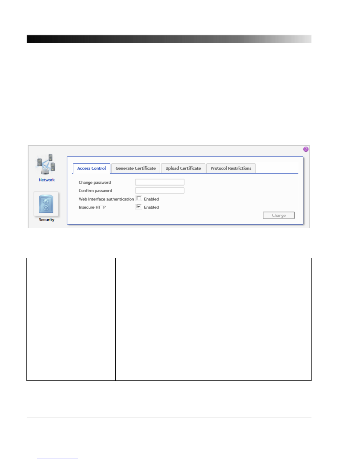
7.3.2 Security Configuration Page
Use the Security page to configure the security of the OTMC 100. It is possible to activate password
protection for accessing the OTMC 100, generate and define authentication certificates for accessing
the OTMC 100 via the secure HTTPS protocol and to disable remote configuration of the OTMC 100,
for example via the OMICRON Device Browser or the PTP and SNMP management interfaces.
Select the corresponding tab to specify the security options to be used by the OTMC 100.
7.3.2.1
Access Control tab
Use this tab to define password protection for accessing the OTMC 100. Click the Change button to
save and apply your access control settings to the OTMC 100.
Change password Enter your password for accessing the OTMC 100. The OTMC 100
uses the same password for all services and processes running on
the OTMC 100 (e.g., detection by OMICRON OMFIND service, FTP
access, etc.)
The password is case sensitive and must have at least 5 characters
(letters, figures or special characters).
Confirm password Repeat your password for confirmation.
Web Interface authentication
enabled
Select the check box to activate password protection using the
currently defined password. If enabled, a login dialog appears when
accessing the OTMC 100 Web Interface.
The OTMC 100 is delivered with the default password timeserver.
Once the password has been changed, the new password is used
when selecting this check box.
OTMC 100 Series User Manual
62
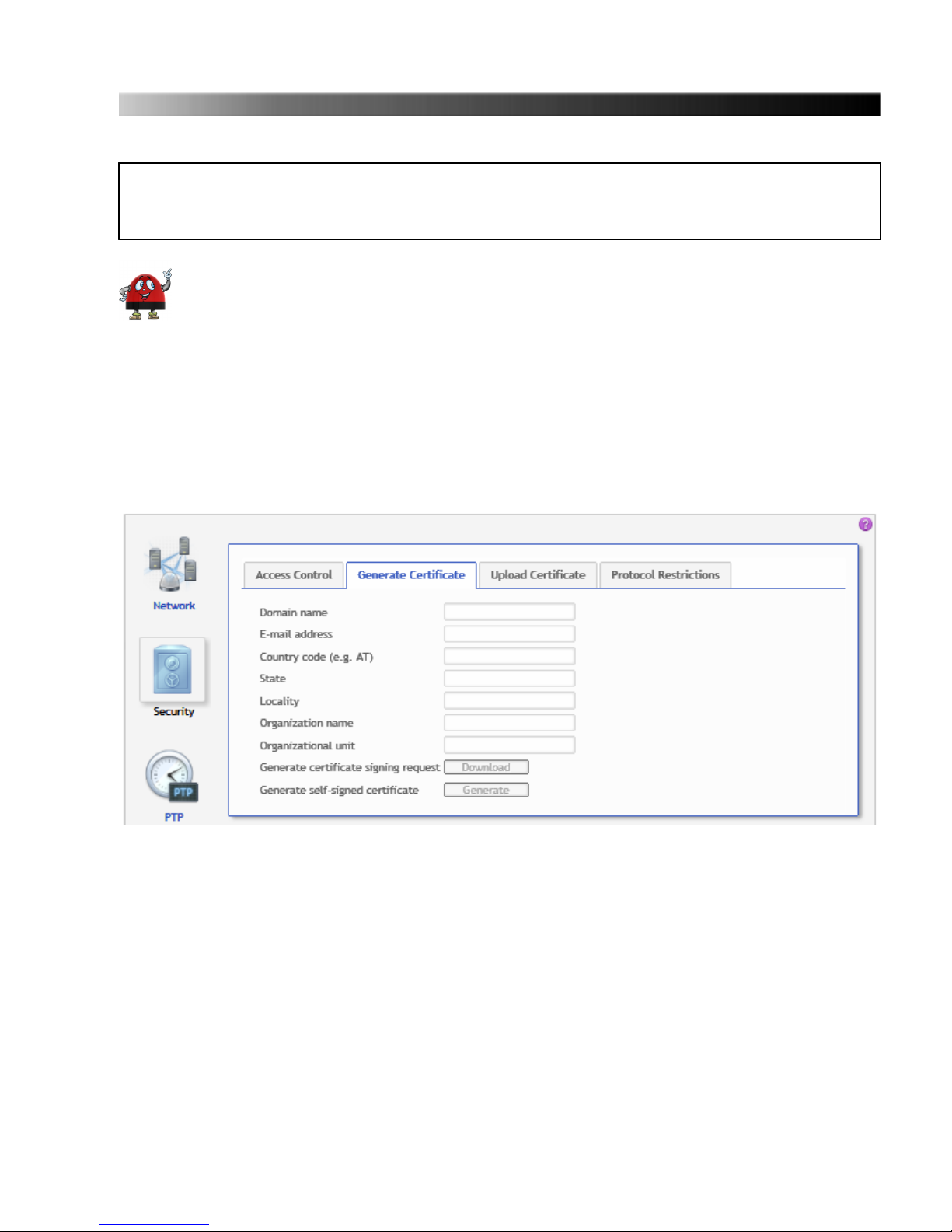
Insecure HTTP enabled If this check box is selected, the OTMC 100 can be accessed via
the HTTP protocol. If deselected, access is only possible via the
secure HTTPS protocol.
In order to deactivate an existing password protection, just deselect the Web Interface
authentication enabled check box, and click the Change button to apply your settings to
the OTMC 100. Attention: If you select the checkbox again, the OTMC 100 will automatically
use the last valid password defined. Therefore, make sure to keep your password stored at a
save place for future use even if you deactivate password protection.
Perform a factory reset on the device if you forgot your password (see "6.2 Operating
Procedures Performed Directly on the Device" on page 31). This will reset the OTMC 100 to
the default password timeserver.
7.3.2.2 Generate Certificate tab
When accessing the OTMC 100 via HTTPS, an "untrusted connection" message will appear because
the OTMC 100 does not have a valid certificate.
To avoid such messages, it is necessary to provide the OTMC 100 with such a certificate. There are
two possible ways: Generating a certificate signed by an accredited certification authority or
generating a certificate signed by yourself.
Web browsers usually contain the digital signatures of all accredited certification authorities by default
and will therefore accept certificates signed by those authorities. However, when using a self-signed
certificate, the web browser will not recognize you as a valid certification authority (since it does not
know the signature of "your" certification authority) and thus not accept such certificates. This behavior
The OTMC 100 Web Interface
63

can only be eliminated by providing each web browser used to access the OTMC 100 with the digital
signature of "your" certification authority. Due to this, generating a self-signed certificate will in most
cases not be a feasible solution in practice. We recommend to generate a certificate signed by an
accredited certification authority or to accept the "untrusted connection" message displayed when
accessing the OTMC 100.
Proceed as follows to generate a certificate signed by an accredited certification authority:
1. Enter the reqired information to the fields Domain name, E-mail address, Country code (e.g.
AT), State, Locality, Organization name and Organizational unit.
2. Click the Download button next to Generate certificate signing request to generate a certificate
and download it from the OTMC 100.
3. Send the certificate to an accredited certification authority.
4. Upload the signed certificate received from the certification authority to the OTMC 100 using the
Upload Certificate tab (see below).
5. The web browser will then recognize that the certificate has been signed by an accredited
certification authority and therefore no longer display the "untrusted connection" message when
accessing the OTMC 100.
Proceed as follows to generate a self-signed certificate:
1. Enter the reqired information to the fields Domain name, E-mail address, Country code (e.g.
AT), State, Locality, Organization name and Organizational unit.
2. Click the Generate button next to Generate self-signed certificate to generate a certificate on the
OTMC 100 that is signed by yourself.
3. Deselect the Insecure HTTP enabled option in the Access Control tab and click the Change
button.
4. The OTMC 100 automatically performs a restart of the web server.
5. The web browser then displays an "untrusted connection" message. Add the certificate previously
generated for the OTMC 100 to your web browser.
The approach to add the certificate to the web browser strongly depends on the browser
used to access the OTMC 100. Please consult the help system of your web browser for a
detailed description how to handle certificates with your browser.
OTMC 100 Series User Manual
64

7.3.2.3 Upload Certificate tab
Click the Browse... button to navigate to the signed certificate (see above). The path and file name is
displayed in the field after selecting it in the file open dialog. Then click the Upload button to upload
the certificate to the OTMC 100.
7.3.2.4 Protocol Restrictions tab
Use this tab to increase the security if you are using the OTMC 100 in a network with high security
demands. Deselecting services that are not required or used for operation makes the OTMC 100 safer
against any kind of attacks, for example performed to change the configuration. Deselecting all options
will minimize potential points of attack and thus provide highest security.
Click the corresponding check box to select or deselect an option. All options are selected by default.
Click the Save button to save and apply your protocol restrictions settings to the OTMC 100.
The OTMC 100 Web Interface
65

Allow OMFIND network
configuration
The OMFIND service is used by the OMICRON Device Browser to
automatically detect OMICRON devices in the network. However,
the Device Browser also allows for changing the IP address of
OMICRON devices available in the network.
Deselect this option to prohibit IP address changes via the
OMICRON Device Browser. If selected, changing the IP address via
the Device Browser is possible.
Allow PTP SET/COMMAND
management messages
Deselect this option to disable write access via the PTP
management interface in order to prohibit configuration of the
OTMC 100 via the PTP management interface.
Allow SNMPv2c community
write access
Deselect this option to disable write access via the SNMP
management interface in order to prohibit configuration of the
OTMC 100 via the SNMP management interface.
Allow SSH password login If this option is enabled, the user can log in to the OTMC 100 via
SSH using the standard user/password authentication (i.e., using
the user name and password defined for the OTMC 100) or using a
public/private key pair previously generated by the user and copied
to the OTMC 100.
Deselect this option to prohibit standard user/password
authenticated access to the OTMC 100 via secure shell (SSH).
When deselected, access via SSH is only possible via key based
authentication. Deselecting this option reduces the risk of
unauthorized access to the OTMC 100 through brute force attacks.
There are numerous instructions for generating SSH key
pairs on the Internet.
OTMC 100 Series User Manual
66
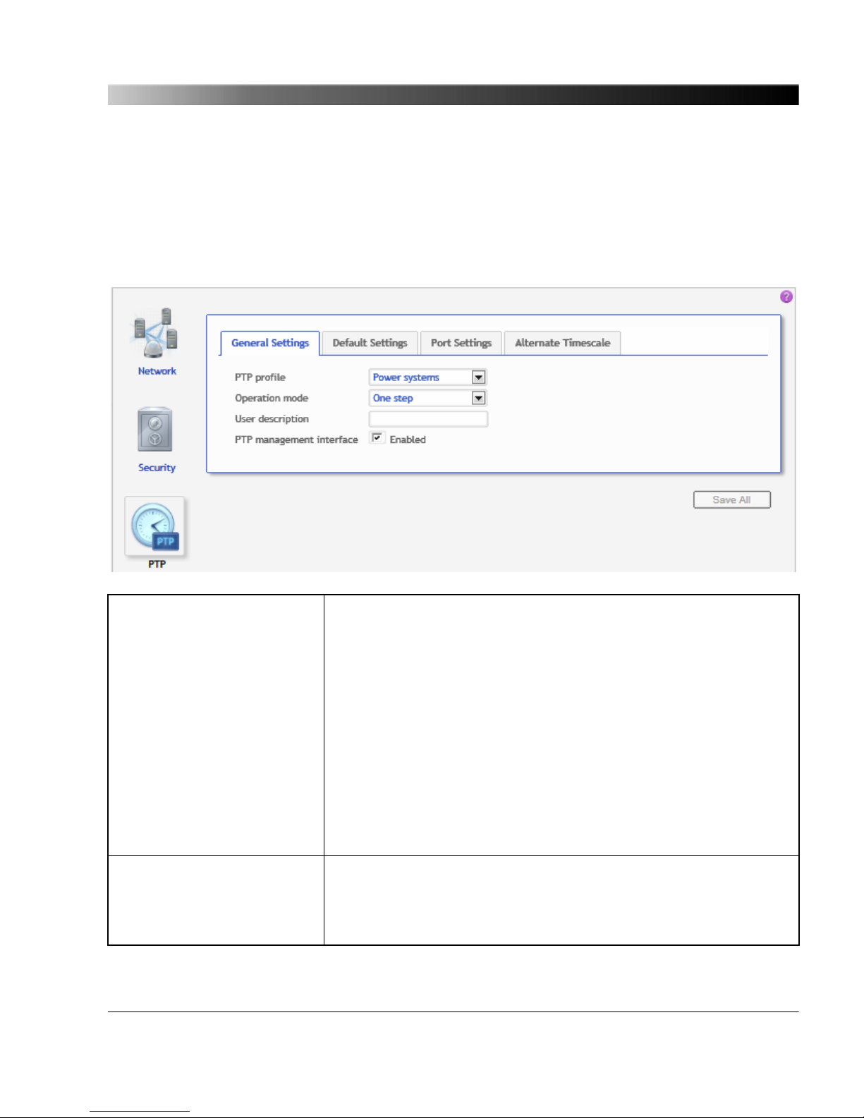
7.3.3 PTP Configuration Page
Select the corresponding tab to specify your PTP configuration settings. Click the Save All button to
save and apply your PTP configuration specified in the individual tabs to the OTMC 100.
7.3.3.1 General Settings tab
PTP profile Use this list box to select the PTP profile. The Default E2E and PTP
profiles are intended for application in industrial environments that
use the IEEE 1588-2008 Precision Time Protocol.
Default E2E: The default profile with the end-to-end mechanism as
defined in IEEE 1588-2008 is used.
Default P2P: The default profile with the peer-to-peer mechansim is
used.
Power systems: The Power Profile acc. to IEEE C37.238-2011 is
intended for application in power system environments that use the
Precision Time Protocol according to the IEEE Std. C37.238-2011
(IEEE Standard Profile for Use of IEEE 1588-2008 Precision Time
Protocol in Power System Applications). (OTMC 100p only.)
Operation mode Use this list box to select the operating mode for the PTP clock
according to IEEE 1588-2008 (One step or Two step).
...
The OTMC 100 Web Interface
67
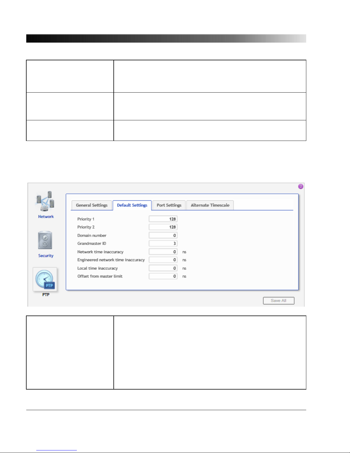
Operation mode (cont.) One step is the recommended mode since this mode produces less
network traffic. The two step mode should only be used if some
equipment used in the network does not work correctly with the one
step mode.
User description Enter a description for the OTMC 100. This may be required to
identify the OTMC 100 uniquely if you are using more than one
OTMC 100 devices in the network.
PTP management interface
enabled
Select the check box to enable access via the PTP management
interface.
7.3.3.2 Default Settings tab
Priority 1
Priority 2
Use this field to specify the priority values. To each PTP master
clock, two priority values (Priority 1 and Priority 2) may be assigned
by the user. If more than one PTP grandmaster clock is available in
the network, a clock with a lower Priority 1 value will always be a
preferred master clock over a clock with a higher Priority 1 value
(see IEEE 1588-2008, clause 6.6.2.3). A value in the range from 0
to 255 may be assigned to the Priority 1 parameter (see
IEEE 1588-2008, clause 7.6.2.2).
...
OTMC 100 Series User Manual
68

Priority 1, Priority 2 (cont.) The Priority 2 parameter (see IEEE 1588-2008, clause 7.6.2.3) is
used if several devices have the same Priority 1 parameter value
and the same clock quality (class, accuracy and variance). The
Priority 2 parameter thus allows a finer grained ordering among
otherwise equivalent clocks (see IEEE 1588-2008, clause 6.6.2.3).
Lower values take precedence.
Domain number Use this field to specify the domain number. The domain number
specifies the PTP domain (see IEEE 1588-2008, clause 7.1) in
which the OTMC 100 participates. All clocks in a network that shall
be synchronized to each other must participate in the same PTP
domain, i.e., have the Domain number parameter set to the same
value.
Grandmaster ID Use this field to specify the grandmaster identity to be transmitted in
IEEE C37.238 TLV. By sending this ID, the OTMC 100 identifies
itself as a valid power profile grandmaster. A power profile slave will
ignore all masters that do not provide a setting for this field. Only
available for Power Profile (OTMC 100p only).
Network time inaccuracy Use this field to specify the network time inaccuracy in ns to be
transmitted in IEEE C37.238 TLV. See IEEE C37.238-2011, clause
5.13. Only available for Power Profile (OTMC 100p only).
Engineered network time
inaccuracy
Use this field to specify the engineered network time inaccuracy in
ns. This value is set at the end device to represent the worst
network time inaccuracy from this device to all preferred
grandmasters. See "EngTimeInacc" in IEEE C37.238-2011. Only
available for Power Profile (OTMC 100p only).
Local time inaccuracy Use this field to specify the maximum time inaccuracy in ns that the
device contributes to the network time inaccuracy. See
IEEE C37.238-2011, clause 5.13. Only available for Power Profile
(OTMC 100p only).
Offset from master limit Use this field to specify the offset from master limit in ns to generate
OfstExceedsLimit event. If this value is zero, no event is generated.
See "OfstExceedsLimit" in IEEE C37.238-2011. Only available for
Power Profile (OTMC 100p only).
The OTMC 100 Web Interface
69
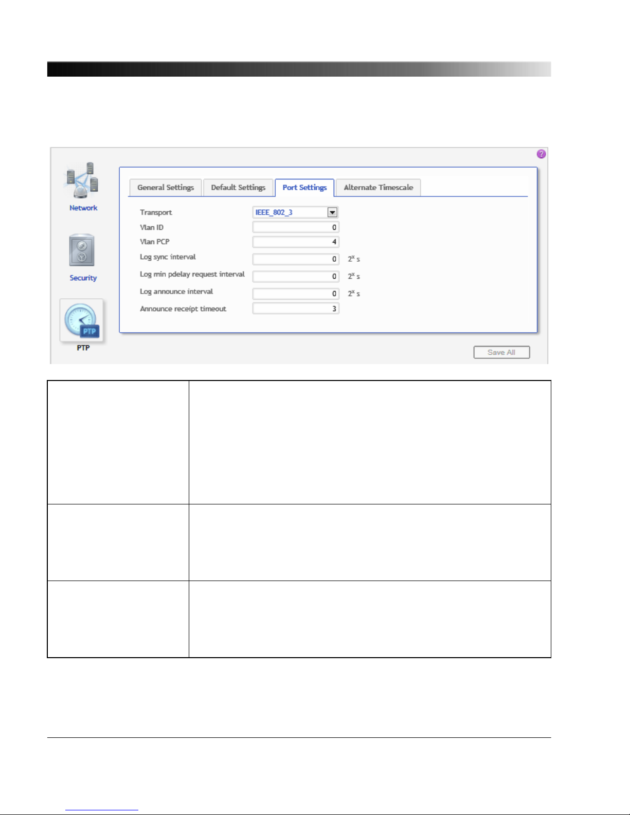
7.3.3.3 Port Settings tab
Transport Select the transport mechanism (network protocol) from the list. The
protocols available in the list depend on the PTP profile selected:
UDP_IP_V4: User Datagram Protocol (UDP) for Internet Protocol (IP)
version 4. Only available for the default E2E and P2P profiles.
UDP_IP_V6: User Datagram Protocol (UDP) for Internet Protocol (IP)
version 6. Only available for the default E2E and P2P profiles.
IEEE_802_3: Ethernet protocol according to IEEE 802.3.
VLan ID Use this field to specify the VLan ID. The Power Profile according to
IEEE C37.238-2011 requires an IEEE 802.1Q VLAN tag. This value
represents the VID (VLAN Identifier) field (12 bits) within the TCI (Tag
Control Identifier). See "VlanId" in IEEE C37.238-2011. Only available
for Power Profile (OTMC 100p only).
VLan PCP Use this field to specify the VLan PCP. The Power Profile according to
IEEE C37.238-2011 requires an IEEE 802.1Q VLAN tag. This value
represents the PCP (Priority Code Point) field (3 bits) within the TCI
(Tag Control Identifier). Only available for Power Profile (OTMC 100p
only).
OTMC 100 Series User Manual
70

Log sync interval Use this field to specify the logarithm to the base 2 of the mean
synchronization interval (interval between successive Sync messages
in 2x seconds) for multicast messages. See "logSyncInterval" in
IEEE 1588-2008.
For example, a value of 2 will result in a synchronization interval of 4
seconds (= 22).
Note:
Sync interval = 2
Log sync interval
seconds, see IEEE 1588-2008, clause
8.2.5.4.3.
Log min pdelay request
interval
Use this field to specify the logarithm to the base 2 of the minimum
permitted mean time interval between successive Pdelay_Req
messages (interval in 2x seconds). See "logMinPdelayReqInterval" in
IEEE 1588-2008. Only available for PTP profile "Default P2P" and
"Power Systems"!
For example, a value of 0 will result in an interval of 1 second (= 20).
Note:
Minimum pdelay request interval = 2
Log min pdelay request interval
seconds, see
IEEE 1588-2008, clause 8.2.5.4.5.
Log min delay request
interval
The logarithm to the base 2 of the minimum permitted mean time
interval between successive Delay_Req messages (interval in 2
x
seconds). This value is determined and advertised by a master clock
based on the ability of the master. Only available for PTP profile
"Default E2E"!
For example, a value of 1 will result in an interval of 2 seconds (= 21).
Range:
Log sync interval <= Log minimum delay request interval <=
Log sync interval + 5
Note:
Minimum delay request interval = 2
Log min delay request interval
seconds, see
IEEE 1588-2008, clause 8.2.5.3.2.
See IEEE 1588-2008 for more detailed information.
Log announce interval
Use this field to specify the mean time interval in 2x seconds between
successive Announce messages. See "logAnnounceInterval" in
IEEE 1588-2008.
For example, a value of 1 will result in an interval of 2 seconds (= 21).
The OTMC 100 Web Interface
71
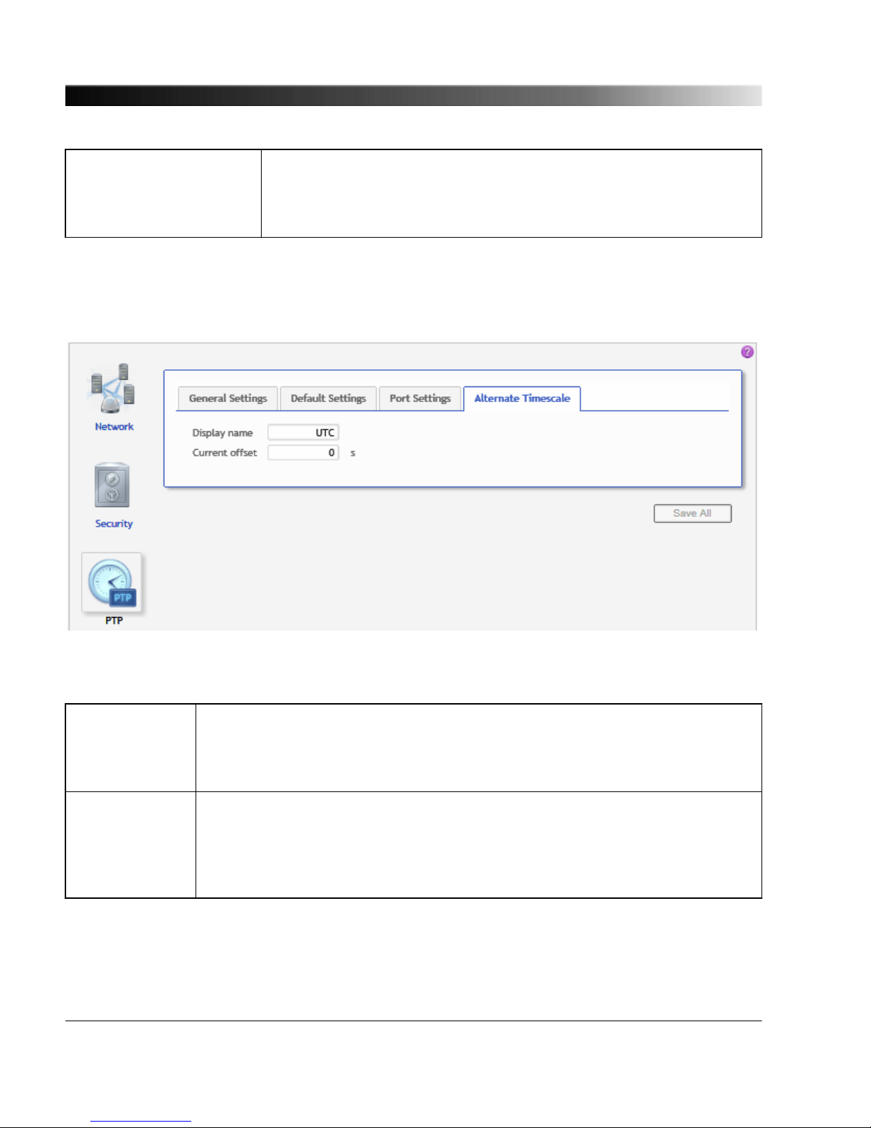
Announce receipt timeout Use this field to specify the number of "Log Announce Interval" intervals
that have to pass without the receipt of an Announce message before
an ANNOUNCE_RECEIPT_TIMEOUT_EXPIRES event occurs. See
"announceReceiptTimeout" in in IEEE 1588-2008.
7.3.3.4 Alternate Timescale tab (only available for Power Profile)
This tab is only available for the Power Profile according to IEEE C37.238-2011 supported by the
OTMC 100p.
Display name Use this field to specify the designation of the alternate timescale
(ALTERNATE_TIME_OFFSET_INDICATOR TLV). Text of max. 10 characters.
See "displayname" and "ALTERNATE_TIME_OFFSET_INDICATOR" in
IEEE 1588-2008 (clause 16.3.3.7) and IEEE C37.238-2011.
Current offset Use this field to specify the value for the
ALTERNATE_TIME_OFFSET_INDICATOR TLV. This is the offset (in seconds)
of the alternate time from the node time. The alternate time is the sum of this
value and the node time. See "ALTERNATE_TIME_OFFSET_INDICATOR" in
IEEE 1588-2008 (clause 16.3.3.4) and IEEE C37.238-2011.
OTMC 100 Series User Manual
72

7.3.4 NTP Configuration Page
The NTP server on the OTMC 100 requires an accurate time source before any NTP client can
synchronize to it. Two time sources are possible: GPS or external NTP servers. If at least one time
source becomes available, it will take a few seconds until the NTP server synchronizes to the time
source.
Select the corresponding tab to specify your NTP configuration settings. Click the Save All button to
save and apply your NTP configuration specified in the individual tabs to the OTMC 100.
7.3.4.1
External Servers tab
Use this tab to specify external NTP servers, for example to improve safety if the GPS signal fails. If
you are exclusively using GPS as an NTP time source it is not necessary to specify an NTP server on
this tab.
Server 1
Server 2
Server 3
Use the Server list box to select 1 to 3 sources the OTMC 100 should receive
NTP time information from if it is not locked to GPS satellites. The more
sources you specify, the more accurate is the NTP time information the
OTMC 100 can deliver.
...
The OTMC 100 Web Interface
73
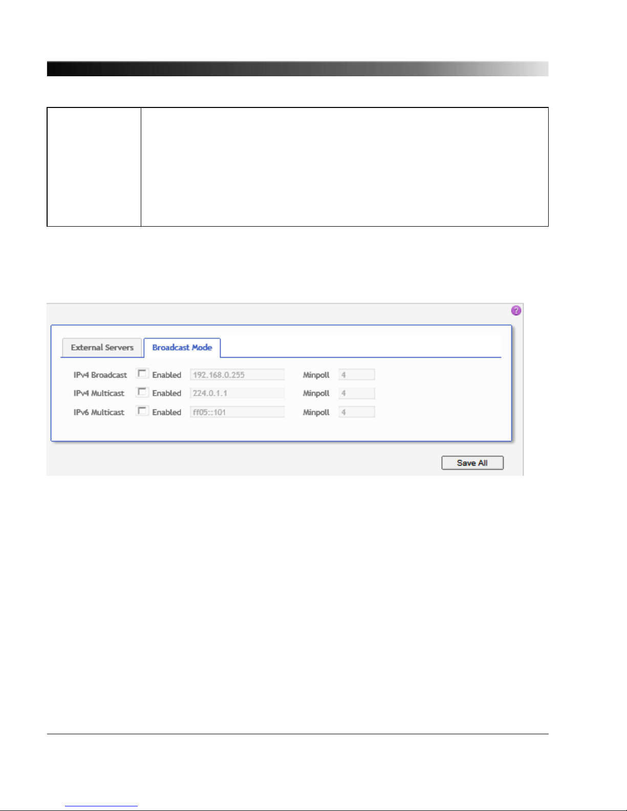
Server 1, 2, 3
(cont.)
Select IPv4 or IPv6 and enter the address of an NTP time server (e.g.
pool.ntp.org) to the respective field. Or select Disabled if you do not want to use
it.
Use the corresponding Minpoll and Maxpoll fields to enter the minimum and
maximum polling interval as a power of 2 (i.e., in 2x seconds). For example, if
you enter a value of 5, the OTMC 100 will poll the NTP time server every 32
seconds (= 25).
Possible values: 4 to 17 resulting in an interval between 16 and 131072 seconds.
7.3.4.2 Broadcast Mode tab
The most common configuration is the client/server mode where every client sends a request to the
server to retrieve the current time. No separate configuration is required for this mode.
The broadcast/multicast mode works by broadcasting the time into the network. In this case, the
clients must be configured to listen for broadcast/multicast messages in the network. This mode can
be configured on this tab.
Explanation:
Broadcast means that data packets are sent from one point (here: OTMC 100) to all other subscribers
of a computer network. Broadcast is not supported by IPv6.
Multicast means that data packets are sent to a specific subset of subscribers only. This subset of
subscribers is specified by an address range, the multicast address. Multicasting therefore allows
much more efficient distribution of information.
OTMC 100 Series User Manual
74

IPv4 Broadcast Select the Enabled check box to enable the sending of IPv4 broadcast
messages containing NTP time information.
If enabled, enter the broadcast IP address in dot-decimal notation (e.g.:
192.168.0.255).
Minpoll specifies the interval for sending the broadcast messages as a power of
2 (i.e., in 2x seconds).
Possible values for Minpoll: 4 to 17 resulting in a broadcast interval between 16
and 131072 seconds.
IPv4 Multicast Select the Enabled check box to enable the sending of IPv4 multicast messages
containing NTP time information.
If enabled, enter the IPv4 multicast address in dot-decimal notation (e.g.:
224.0.1.1).
Minpoll specifies the interval for sending the multicast messages as a power of 2
(i.e., in 2x seconds).
Possible values for Minpoll: 4 to 17 resulting in a broadcast interval between 16
and 131072 seconds.
IPv6 Multicast Select the Enabled check box to enable the sending of IPv6 multicast messages
containing NTP time information.
If enabled, enter the IPv6 multicast address in hexadecimal notation (e.g.:
ff05::101).
Minpoll specifies the interval for sending the multicast messages as a power of 2
(i.e., in 2x seconds).
Possible values for Minpoll: 4 to 17 resulting in a broadcast interval between 16
and 131072 seconds.
See the "ntp.conf man page" for a more detailed description of the NTP parameters (see
Linux command "man ntp.conf").
The OTMC 100 Web Interface
75

7.3.5 Log & Notifications Page
Select the corresponding tab to specify your settings for the logging of system messages and the
event notification. Click the Save All button to save and apply your log & notification settings specified
in the individual tabs to the OTMC 100.
7.3.5.1 Log tab
Level Use this list box to select the level as of which you want to have system
messages logged to the selected target. Lower levels include the
messages of higher levels.
The following levels are available (starting from the lowest level): Debug,
Info, Notice, Warning, Error, Critical, Emergency.
OTMC 100 Series User Manual
76

Target Use this list box to select the target where you want to have the system
messages logged to:
Local logfile only: Logging is performed to the internal log file that can be
viewed using the Log Viewer page (see page 55) in the Status section.
IPv4 syslog server and IPv6 syslog server: Logging is performed to the
internal log file and to the specified syslog server for IPv4 or IPv6 installed
in the network.
Remote host &
Remote port
Use this field to specify the host name and port number of the syslog
server in the network used as log target for the system messages.
Only active if the Target list box is set to IPv4/IPv6 syslog server.
Remote transport Use this field to specify the network transport protocol of the IPv4 or IPv6
syslog server, if selected in the Target field.
Select UDP (User Datagram Protocol) or TCP (Transmission Control
Protocol).
Enabled sources Select the corresponding check box to enable logging for a particular
message type (e.g., GPS messages, PTP messages, etc.).
The OTMC 100 Web Interface
77
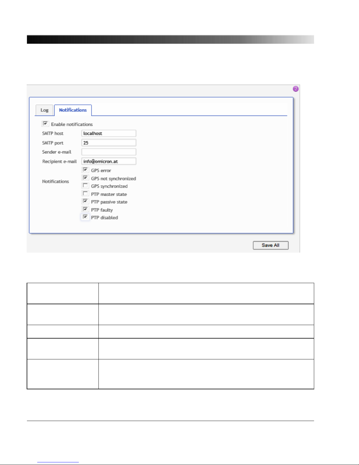
7.3.5.2 Notifications tab
The event notification function can be used to generate e-mail messages on the occurrence of specific
events.
Enable notifications Select the check box to enable the event notification function and activate
the fields and controls in this tab.
SMTP host &
SMTP port
Use this field to specify the host name and port number of the SMTP (e-
mail) server.
Sender e-mail Use this field to specify the e-mail address of the OTMC 100.
Recipient e-mail Use this field to specify the recipient e-mail address for the event
notification messages.
Notifications Select the corresponding check box to enable e-mail notification for an
event.
GPS error: Notification in case of GPS errors.
OTMC 100 Series User Manual
78

GPS not synchronized: Notification if the OTMC 100 has lost GPS
synchronization.
GPS synchronized: Notification if the OTMC 100 gained GPS
synchronization.
PTP master state: Notification if the OTMC 100 entered the PTP master
state. The PTP master state is automatically assigned to the PTP clock
that is able to provide the most accurate time information of all clocks
available in the network.
PTP passive state: Notification if the OTMC 100 left the PTP master state
because it is no longer able to provide accurate time information or, if
more than one PTP grandmaster clock is available in the network,
because another grandmaster clock provides more accurate time
information than the OTMC 100.
PTP faulty: Notification if PTP time information is no longer available in
the network due to an occurring error in the OTMC 100.
PTP disabled: Notification if the Precision Time Protocol (PTP) service
has been disabled in the Network configuration (see page 58) .
The OTMC 100 Web Interface
79

7.3.6 SNMP Configuration Page
Configuration via the Simple Network Management Protocol (SNMP) is only possible for the power
profile settings (as defined by IEEE C37.238-2011 MIB) of the OTMC 100p. No other settings can be
configured via SNMP.
Use this page to configure the access via the Simple Network Management Protocol (SNMP). Click
the Save All button to save and apply your SNMP configuration specified in the individual tabs to the
OTMC 100.
A MIB file is required for proper representation of the OTMC 100 settings in SNMP clients.
Refer to the Device Control page (see page 83) of the Tools section to download the MIB
file from the OTMC 100.
7.3.6.1 Access tab
OTMC 100 Series User Manual
80
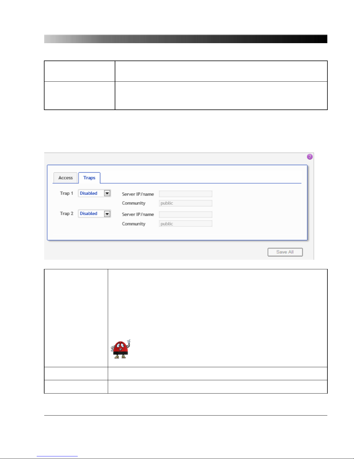
Read community Use this field to specify the community name for read access. SNMP
clients of this community can obtain read access to the OTMC 100.
Read/write community Use this field to specify the community name for read and write access.
SNMP clients of this community can obtain read and write access to the
OTMC 100.
7.3.6.2 Traps tab
Trap 1
Trap 2
The OTMC 100 is able to act as an SNMP agent that actively sends
messages to an SNMP manager in case of occurring events. You can
specify two separate SNMP managers (Trap 1 and Trap 2) as the recipients
of these messages.
Select Disabled from the list box to disable this function. Or select Trap to
send a trap message or Inform to send an inform request to the SNMP
manager in case of an occurring event.
Such messages can only be initiated by the notifications defined in
the power profile.
Server IP/name Use this field to enter the IP address of the server acting as SNMP manager.
Community Use this field to define the community name.
The OTMC 100 Web Interface
81

7.4 Tools
The following pages are available in the Tools section:
Device Control
(see page 83)
Software Upgrade
(see page 84)
Configuration Management
(see page 85)
OTMC 100 Series User Manual
82

7.4.1 Device Control Page
Reboot device Click the Reboot button to initiate a device reboot.
A reboot can also be performed using the pushbutton on the device.
Factory reset Click the Reset button to initiate a factory reset in order to reset the device
configuration to the factory defaults. The factory reset deletes all user
specific settings.
A factory reset can also be performed using the pushbutton on the device.
System snapshot Click the Download button to download a system snapshot containing all
configuration settings and the log file. The system snapshot contains
important information for the technical support in case of problems.
SNMP MIB File A MIB (Management Information Base) file is required for proper
representation of the power profile settings of the OTMC 100p in SNMP
clients. Click the Download button to download the MIB file from the
OTMC 100p.
The OTMC 100 Web Interface
83

7.4.2 Software Upgrade Page
Installed software version Displays the version number of the software currenty installed on
the OTMC 100.
Choose image file Click the Browse... button to navigate to the software image file.
The path and file name is displayed in the field after selecting it in
the file open dialog.
Keep settings If this check box is selected, the user specific configuration settings
are kept during a software update. Deselect the check box to
automatically reset the device configuration to the factory defaults
after a software update.
Update button Click the Update button to start the software update. The update
process may take several minutes. Do not disconnect the
OTMC 100 or the computer during this process.
The OTMC 100 automatically restarts after the software update
completed.
If the software update process fails due to any reason, the OTMC 100 will enter a recovery
mode on the next power-up. In this mode, the device provides only a rudimentary Web
Interface (similar to the Software Upgrade page) just allowing for the upload of a software
image.
OTMC 100 Series User Manual
84

7.4.3 Configuration Management Page
Upload
XML configuration Use this function to upload a prepared configuration file to the OTMC 100
and apply this configuration on the device.
Click the Browse... button to navigate to the XML configuration file. The
path and file name is displayed in the field after selecting it in the file open
dialog. Click the Save button to upload and save the configuration file to
the OTMC 100.
Download
XML configuration Click the Download button next to XML configuration to download the
current configuration of the OTMC 100 in XML format.
XSD Click the Download button next to XSD to download the XML Schema
Definition defining the XML structure of the XML configuration file from the
OTMC 100.
The OTMC 100 Web Interface
85

8 Automation Interface
The OTMC 100 series offers secure shell (SSH) access to its internal Linux operating system for
remote configuration.
It provides the following functionality:
• Configuration management (backup and restore)
• Download of log files
• Usage of Linux shell utilities (e.g. ping)
8.1 Access
The OTMC 100 supports TFTP, FTP and SSH access. By default you can login via FTP/SSH using
the user name omicron and the password timeserver. The Web Interface, the SSH, and the FTP
server use the same password. Therefore, changing the password in the Web Interface will also
update the password for the other services.
Anonymous access is possible via TFTP and FTP, however, without the option to upload files. In order
to upload files, we recommend the secure SCP (Secure Copy) instead of FTP, where passwords are
not transmitted in plain text. Note that the TFTP and FTP services can also be disabled if not needed.
The log and configuration files are located in the home directory of user omicron ("/home/omicron") in
the respective subfolders "config" and "log".
8.2 Configuration
All configuration options are stored in a single XML file that can be edited easily. The XML file contains
the same options as the Web Interface (which is in fact just a front end for the XML file). Additionally,
an XML Schema Definition (XSD) is provided to ensure that only valid configuration options are set.
This makes it possible to easily clone a device even from distant locations. Just download the
configuration file from one OTMC 100, edit it if required (e.g. change the IP address) and upload it to
another OTMC 100.
Further instructions regarding the automated configuration via SSH can be found in the readme file
located under "/home/omicron/doc/readme.txt".
OTMC 100 Series User Manual
86

9 The OMICRON Device Browser
By means of the OMICRON Device Browser you can access network compatible OMICRON devices.
The Device Browser automatically finds all OMICRON devices available in the computer network.
Having the Device Browser installed on your computer, the OMICRON devices may be displayed in
one of two ways:
1. When using the regular Windows Explorer, the OMICRON devices appear in the Windows
Explorer’s folder tree in a section called OMICRON Devices, their serial numbers presented like
regular first-level folders.
If necessary, right-click on a free area of the Windows Explorer’s folder tree and select the Show
all folders option to display the OMICRON Devices section in the Windows Explorer.
2. Alternatively, double click the OMICRON Devices desktop icon. This launches a Windows Explorer
window listing the OMICRON devices detected in the computer network with their serial number,
device type/name and IP address.
There is no functional difference; use whatever method is more convenient for you. Even though the
Device Browser help system focuses on accessing devices via the "regular" Windows Explorer, when
working from the OMICRON Devices Explorer window, the handling is basically identical.
Click the help button in the top right corner of the Device Browser Explorer window to view the
Device Browser help providing detailed information about the Device Browser.
The OMICRON Device Browser
87

9.1 Installing the OMICRON Device Browser
The OMICRON Device Browser and its installation program Setup Wizard are included on the
CD ROM accompanying the OTMC 100. Proceed as follows to install the OMICRON Device Browser:
1. Exit all other major programs running on your computer.
2. Insert the CD ROM into your computer’s CD ROM drive and click Install Device Browser on the
start page. Should the start page not be displayed automatically a few seconds after the CD has
been inserted into the CD ROM drive, change to the Windows Explorer and double-click
autorun.exe on the CD ROM.
3. Follow the instructions displayed on the screen to install the software.
Note regarding firewall requirements: The OMFind service sends and receives network
packets on UDP port 4987 and 4988. The OMICRON Device Browser installer will configure
the Windows firewall appropriately during installation on supported systems. If you have a
separate "personal" firewall enabled, ensure that UDP ports 4987 and 4988 are open for the
OMFind service.
9.2 Finding OMICRON Devices in the Device Browser Manually
(OMFind)
Normally the Device Browser automatically finds the OMICRON devices connected to the network. If
not, it is also possible to manually search the network for available OMICRON devices.
Proceed as follows:
1. Right-click the OMICRON Devices desktop icon.
2. On the context menu, select OMFind and then click Find Devices.
3. This will start the Device Discovery tool. This tool is intended to diagnose network/firewall problems
when the Device Browser lists no or not all expected test sets.
4. Click the Start Discovery button to manually search for OMICRON devices connected to the
network. Once the search is finished, the Discovered devices section lists network parameters of
all found OMICRON devices.
Some of the available firewall/tunneling products are capable of stopping even the Start
Discovery feature of the Device Discovery tool. So you will not find any OMICRON devices
on the network this way. In this case, the network parameters list stays empty once a search
is finished. If you experience such a behavior, this may indicate a firewall/tunneling software
blocking the network communication.
OTMC 100 Series User Manual
88
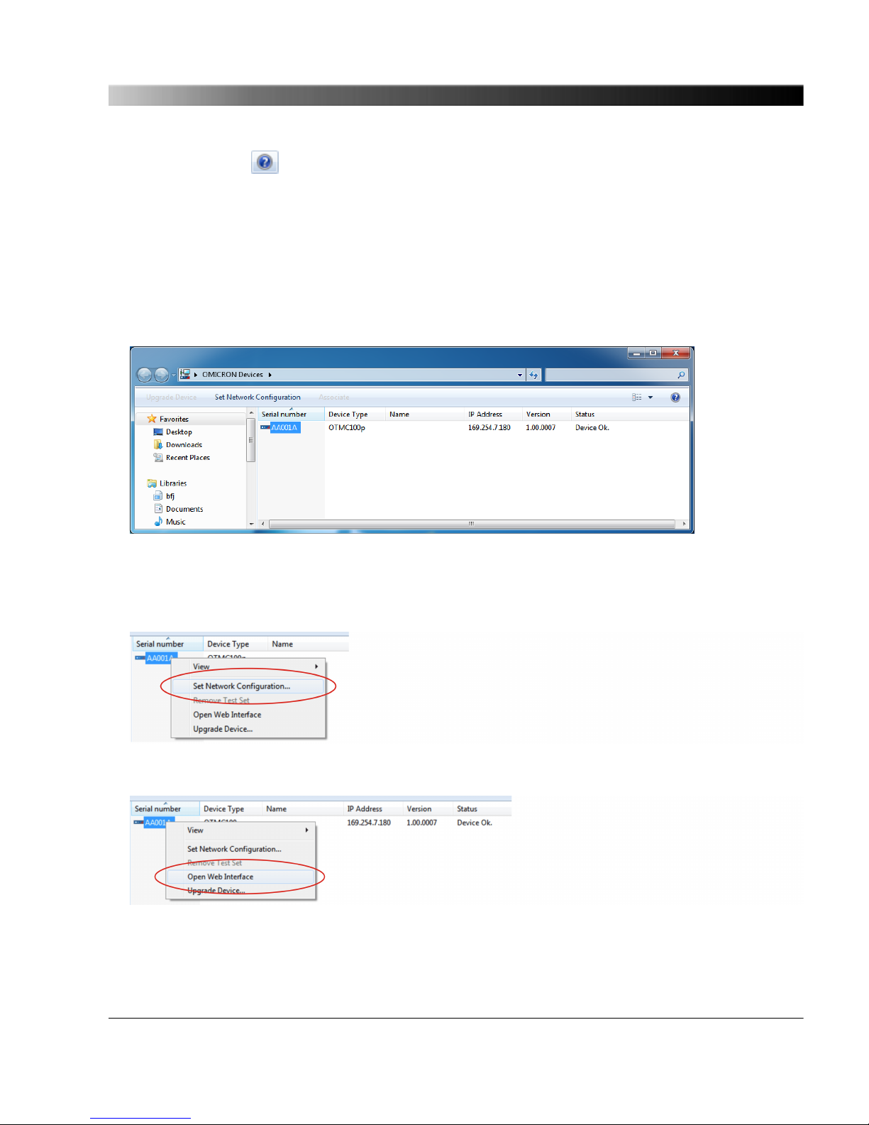
Click the help button in the top right corner of the Device Browser Explorer window to view the
Device Browser help providing detailed information about the OMFind service.
9.3 Accessing the OTMC 100 Web Interface
Proceed as follows to access the OTMC 100 Web Interface:
1. Launch the OMICRON Device Browser.
2. The Device Browser will automatically find and display the OTMC 100.
If the IP address configurations of the OTMC 100 and the computer are not compatible, the
respective status is displayed in the Status column. In this case, right-click the OTMC 100 serial
number and select Set Network Configuration to assign a suitable IP address to the OTMC 100.
3. Right-click the OTMC 100 serial number and select Open Web Interface from the context menu.
4. The start page of the OTMC 100 Web Interface is displayed in a web browser.
The OMICRON Device Browser
89

10 Technical Data
You can find more detailed technical data on the OMICRON Lab web site
www.omicron-lab.com.
10.1 General Specifications
Dimensions Overall height (without connector and mounting kit): 106.2 mm / 4.17"
Diameter: 115.5 mm / 4.55"
Weight < 500 g / 1.1 lbs
Degree of protection IP65 according to EN 60529
Timing accuracy +/- 100 ns to reference time (TAI/UTC)
Ethernet port Waterproof Ethernet connector according to IEC 61076-3-106 (variant 4),
10Base-T/100 Base-TX
Power supply Power over Ethernet (PoE), class 1 powered device according to
IEEE 802.3af
Power consumption < 2 W
GPS performance 12 channel GPS receiver
Frequency: 1575.42 MHz, L1 band
10.2 Environmental Conditions
Temperature range Operation: -40 °C to +70 °C (-40 °F to +158 °F)
Storage: -40 °C to +85 °C (-40 °F to +185 °F)
Weathering resistance For outdoor use (IP65)
OTMC 100 Series User Manual
90

10.3 CE Conformity, Electromagnetic Compatibility (EMC),
Certificates
CE conformity The product adheres to the specifications of the guidelines of the council
of the European Community for meeting the requirements of the member
states regarding the electromagnetic compatibility (EMC) Directive
2004/108/EC.
EMC emission EN 55022:2010 class B, EN 61326-1:2006
EMC immunity EN 55024:2010, EN 61326-1:2006, EN 62305-4:2010
Safety IEC 60950-1:2005 2 Ed. +A1:2009, IEC 60950-22:2005
Certificates
Manufactured under an ISO 9001 registered system.
Technical Data
91

11 Glossary
ATE Automatic Test Equipment
BMCA Best Master Clock Algorithm
BSW British Standard Whitworth
CET / CEST Central European Time / Central European Summer Time
DNS Domain Name System
DNS-SD DNS Service Discovery
E2E End-To-End
FTP File Transfer Protocol
GPS Global Positioning System
HTTP HyperText Transfer Protocol
HTTPS HyperText Transfer Protocol Secure
IED Intelligent Electronic Device
IP Internet Protocol
MAC address Media Access Control address
mDNS Multicast DNS (Domain Name System)
MIB Management Information Base
NTP Network Time Protocol
P2P Peer-To-Peer
PoE Power over Ethernet (according to IEEE 802.3af)
PTP Precision Time Protocol
RFC Request for comment
SCP Secure Copy
SELV Safety Extra Low Voltage
SLAAC Stateless Address Autoconfiguration
OTMC 100 Series User Manual
92

SNMP Simple Network Management Protocol
SSH Secure Shell
TAI International Atomic Time
TCP Transmission Control Protocol
TFTP Trivial File Transfer Protocol
UDP User Datagram Protocol
UT1 Universal Time No. 1. Variant of the Universal Time (UT) used as reference time
for the Universal Time Coordinated (UTC).
UTC Universal Time Coordinated
XML Extensible Markup Language
XSD XML Schema Definition
Glossary
93

OMICRON Service Centers
North and South America
OMICRON electronics Corp. USA
3550 Willowbend Blvd.
Houston, TX 77054, USA
Phone: +1 713 830-4660 or 1 800 OMICRON
E-Mail: support@omicron-lab.com
Web site: www.omicron-lab.com
Asia, Pacific
OMICRON electronics Asia Ltd.
Suite 2006, 20/F, Tower 2
The Gateway, Harbour City Kowloon, Hong Kong S.A.R.
Phone: +852 3767 5500
E-Mail: support@omicron-lab.com
Web site: www.omicron-lab.com
Europe, Africa, Middle East
OMICRON electronics GmbH
Oberes Ried 1
6833 Klaus, Austria
Phone: +43 5523 507-333
E-Mail: support@omicron-lab.com
Web site: www.omicron-lab.com
For address details of other OMICRON Service Centers in your area, please visit our web site
www.omicron-lab.com.
OTMC 100 Series User Manual
94

Index
A
about the OTMC 100 ..................................... 7
about this manual .......................................... 6
accessing the OTMC 100 ...................... 21, 89
accessories .................................................. 10
addresses .................................................... 94
automation interface .................................... 86
C
certificate for web browser ..................... 63, 65
Configuration section (Web Interface) ......... 57
connecting the OTMC 100 ........................... 19
contact information ...................................... 94
D
designated use .............................................. 7
Device Browser ..................................... 21, 87
device configuration, upload/download ....... 85
device overview ........................................... 12
E
E-Mail notification ........................................ 76
Ethernet cable
patch cable (scope of delivery) ............... 10
possible length ................................... 7, 19
shielded cable for installation
outside .............................................. 14, 19
F
factory reset ..................................... 29, 32, 83
finding OMICRON devices manually ........... 88
G
glossary ....................................................... 92
GPS status ...................................... 27, 36, 40
H
help, display online help .............................. 34
HTTPS (enable/disable) .............................. 62
I
installing the OMICRON Device Browser .... 88
introduction to the OTMC 100 ....................... 7
IP address ................................. 21, 36, 53, 89
configuration ..................................... 58, 59
IP address assignment (manual assignm.) . 30
L
LED status indication ................................... 12
lightning protection ................................ 14, 19
Index
95

log & notifications ........................................ 76
log file .............................................. 30, 55, 76
login dialog ............................................ 21, 27
M
manual IP address assignment ................... 30
manual, display PDF manual ....................... 34
manufacturer address .................................. 94
mast mounting ............................................. 16
mast mounting kit .................................. 10, 16
MIB file ................................................... 80, 83
mounting instructions ................................... 16
mounting positions ....................................... 14
N
network configuration ............................ 24, 58
network status ....................................... 27, 53
network topology, typical ............................. 19
notification by E-Mail ................................... 76
NTP configuration ........................................ 73
NTP status ....................................... 27, 36, 50
O
OMFind ........................................................ 88
OMICRON Device Browser ................... 21, 87
OMICRON service centers .......................... 94
operation
assign IP address ................................... 30
factory reset ...................................... 29, 32
GPS, PTP, NTP, network status ............ 27
operation directly on the device .............. 31
operation via Web Interface ................... 27
password definition ................................. 27
reboot ............................................... 28, 31
software update ................................ 28, 32
software upload in recovery mode ... 29, 32
system snapshot .................................... 29
view/export log file .................................. 30
ordering information ..................................... 10
overview (device overview) ......................... 12
Overview section (Web Interface) ............... 36
P
password ............................................... 27, 62
PoE injector ................................................. 19
product name ......................................... 10, 36
protocol restrictions ..................................... 65
PTP configuration .................................. 24, 67
PTP status ....................................... 27, 36, 42
pushbutton ............................................. 12, 31
R
reboot .............................................. 28, 31, 83
recovery mode ....................................... 29, 32
RJ45 connector (waterproof
connector) ............................ 10, 12, 16, 18, 19
OTMC 100 Series User Manual
96

S
safety instructions .................................... 6, 14
scope of delivery .......................................... 10
security configuration ............................. 24, 62
serial number ....................... 21, 36, 53, 58, 87
services (enable/disable) ............................. 60
setting up the OTMC 100, steps .................. 24
SNMP configuration ..................................... 80
SNMP MIB file ....................................... 80, 83
software update ............................... 28, 32, 84
software upload in recovery mode ......... 29, 32
Status section (Web Interface) .................... 39
support ................................................... 34, 94
surge protection device ......................... 14, 19
system log file .................................. 30, 55, 76
system requirements for computer
used to access the OTMC 100 .................... 21
system snapshot .................................... 29, 83
T
technical data .............................................. 90
temporary mounting on a stand ................... 18
Tools section (Web Interface) ...................... 82
W
waterproof RJ45 connector . 10, 12, 16, 18, 19
Web Interface ........................................ 27, 34
Configuration section .............................. 57
operating procedures performed
via Web Interface ................................... 27
Overview section .................................... 36
Status section ......................................... 39
Tools section .......................................... 82
X
XML configuration, upload/download .......... 85
Index
97

www.omicron-lab.com
© 2012 OMICRON Lab
OTMC 100 User Manual engl. V. 1
All rights reserved.
 Loading...