


CT Analyzer & CT SB2
User Manual

CT Analyzer & CT SB2 User Manual
Manual Version: CTAnalyzer+CTSB2UM.AE.3
© OMICRON electronics GmbH 2012. All rights reserved.
This manual is a publication of OMICRON electronics GmbH.
All rights including translation reserved. Reproduction of any kind, for example, photocopying,
microfilming, optical character recognition and/or storage in electronic data processing systems,
requires the explicit consent of OMICRON electronics GmbH. Reprinting, wholly or in part, is not
permitted.
The product information, specifications, and technical data embodied in this manual represent the
technical status at the time of writing and are subject to change without prior notice.
We have done our best to ensure that the information given in this manual is useful, accurate and
entirely reliable. However, OMICRON electronics GmbH does not assume responsibility for any
inaccuracies which may be present.
The user is responsible for every application that makes use of an OMICRON product.
OMICRON electronics GmbH translates this manual from the source language English into a number
of other languages. Any translation of this manual is done for local requirements, and in the event of a
dispute between the English and a non-English version, the English version of this manual shall govern.

CT Analyzer
User Manual

CT Analyzer User Manual
Manual Version: CTAnalyzerUM.AE.3
2

Contents
Contents
Preface . . . . . . . . . . . . . . . . . . . . . . . . . . . . . . . . . . . . . . . . . . . . . . . . . . . . . . .7
Using This Manual . . . . . . . . . . . . . . . . . . . . . . . . . . . . . . . . . . . . . . . . . . . . . . . . 7
Operator Qualifications and Safety Standards. . . . . . . . . . . . . . . . . . . . . . . . . . . 7
Conventions and Symbols Used . . . . . . . . . . . . . . . . . . . . . . . . . . . . . . . . . . . . . 8
Related Documents . . . . . . . . . . . . . . . . . . . . . . . . . . . . . . . . . . . . . . . . . . . . . . . 8
Safety Rules . . . . . . . . . . . . . . . . . . . . . . . . . . . . . . . . . . . . . . . . . . . . . . . . . . .9
General Rules for Safe Operation . . . . . . . . . . . . . . . . . . . . . . . . . . . . . . . . . . . . 9
Orderly Measures . . . . . . . . . . . . . . . . . . . . . . . . . . . . . . . . . . . . . . . . . . . . . . . 10
Disclaimer . . . . . . . . . . . . . . . . . . . . . . . . . . . . . . . . . . . . . . . . . . . . . . . . . . . . . 10
1 Introduction . . . . . . . . . . . . . . . . . . . . . . . . . . . . . . . . . . . . . . . . . . . . . . . . . .11
1.1 Designated Use . . . . . . . . . . . . . . . . . . . . . . . . . . . . . . . . . . . . . . . . . . . . . . . . . 11
1.2 Functional Components of the CT Analyzer . . . . . . . . . . . . . . . . . . . . . . . . . . . 12
1.2.1 Overview. . . . . . . . . . . . . . . . . . . . . . . . . . . . . . . . . . . . . . . . . . . . . . . . . . . . . . 12
1.2.2 Mains Connection Unit and Grounding . . . . . . . . . . . . . . . . . . . . . . . . . . . . . . . 13
1.2.3 Compact Flash Card Slot . . . . . . . . . . . . . . . . . . . . . . . . . . . . . . . . . . . . . . . . . 13
1.2.4 Remote Control Interface (PC Connection) . . . . . . . . . . . . . . . . . . . . . . . . . . . 14
1.2.5 Inputs and Outputs . . . . . . . . . . . . . . . . . . . . . . . . . . . . . . . . . . . . . . . . . . . . . . 15
1.2.6 I/0 Key with Status LEDs . . . . . . . . . . . . . . . . . . . . . . . . . . . . . . . . . . . . . . . . . 16
1.2.7 Display with Soft Keys . . . . . . . . . . . . . . . . . . . . . . . . . . . . . . . . . . . . . . . . . . . 17
1.2.8 Keyboard . . . . . . . . . . . . . . . . . . . . . . . . . . . . . . . . . . . . . . . . . . . . . . . . . . . . . 18
1.3 License-Depending Functional Scope . . . . . . . . . . . . . . . . . . . . . . . . . . . . . . . . 19
1.4 Scope of Delivery, Accessories, Available Licenses . . . . . . . . . . . . . . . . . . . . . 20
2 Setup and Connection. . . . . . . . . . . . . . . . . . . . . . . . . . . . . . . . . . . . . . . . . .21
2.1 General Safety Rules for Connecting and Operating the CT Analyzer . . . . . . . 21
2.2 Setting Up the CT Analyzer . . . . . . . . . . . . . . . . . . . . . . . . . . . . . . . . . . . . . . . . 22
2.3 Connecting the CT Analyzer to a PC (optional). . . . . . . . . . . . . . . . . . . . . . . . . 23
2.4 Connection for Usual Applications. . . . . . . . . . . . . . . . . . . . . . . . . . . . . . . . . . . 24
2.4.1 Wiring for a CT Test . . . . . . . . . . . . . . . . . . . . . . . . . . . . . . . . . . . . . . . . . . . . . 24
2.4.2 Wiring for a Burden Test . . . . . . . . . . . . . . . . . . . . . . . . . . . . . . . . . . . . . . . . . . 26
2.4.3 Wiring for Primary Resistance Measurement . . . . . . . . . . . . . . . . . . . . . . . . . . 27
2.5 Connection for Special Applications . . . . . . . . . . . . . . . . . . . . . . . . . . . . . . . . . 28
2.5.1 Measurement on a Gapped Core . . . . . . . . . . . . . . . . . . . . . . . . . . . . . . . . . . . 28
2.5.2 Excitation Curve Measurement for an Unwound Iron Core . . . . . . . . . . . . . . . 29
2.5.3 Measurement on a GIS (SF6) Switch Gear . . . . . . . . . . . . . . . . . . . . . . . . . . . 30
2.5.4 Measurement on Bushing-Type CTs . . . . . . . . . . . . . . . . . . . . . . . . . . . . . . . . 32
2.5.5 VT Ratio Measurement Using QuickTest . . . . . . . . . . . . . . . . . . . . . . . . . . . . . 38
3

CT Analyzer User Manual
2.5.6 VT Winding Resistance Measurement Using QuickTest . . . . . . . . . . . . . . . . . 39
2.5.7 Polarity Check Using QuickTest and the CPOL Polarity Checker . . . . . . . . . . 39
2.6 Disconnection . . . . . . . . . . . . . . . . . . . . . . . . . . . . . . . . . . . . . . . . . . . . . . . . . . 41
2.7 Improving the Quality of Measurement Results. . . . . . . . . . . . . . . . . . . . . . . . . 42
2.7.1 4-Wire Measurement vs. 2-Wire Measurement . . . . . . . . . . . . . . . . . . . . . . . . 42
2.7.2 Noise Reduction Techniques . . . . . . . . . . . . . . . . . . . . . . . . . . . . . . . . . . . . . . 43
3 Short Guide for Running a CT Test . . . . . . . . . . . . . . . . . . . . . . . . . . . . . . . 45
4 Running a CT Test (Detailed) . . . . . . . . . . . . . . . . . . . . . . . . . . . . . . . . . . . . 49
4.1 Setting Up the CT Analyzer . . . . . . . . . . . . . . . . . . . . . . . . . . . . . . . . . . . . . . . . 50
4.2 Preparing and Configuring the Test. . . . . . . . . . . . . . . . . . . . . . . . . . . . . . . . . . 50
4.3 Running the Automatic Test and Connecting the CT Analyzer . . . . . . . . . . . . . 52
4.4 After the Test is Finished. . . . . . . . . . . . . . . . . . . . . . . . . . . . . . . . . . . . . . . . . . 55
4.5 Disconnection . . . . . . . . . . . . . . . . . . . . . . . . . . . . . . . . . . . . . . . . . . . . . . . . . . 57
5 Operating and Configuring the CT Analyzer. . . . . . . . . . . . . . . . . . . . . . . . 59
5.1 Working in the User Interface . . . . . . . . . . . . . . . . . . . . . . . . . . . . . . . . . . . . . . 59
5.1.1 Displaying a Specific Card . . . . . . . . . . . . . . . . . . . . . . . . . . . . . . . . . . . . . . . . 59
5.1.2 Using the Soft Keys . . . . . . . . . . . . . . . . . . . . . . . . . . . . . . . . . . . . . . . . . . . . . 59
5.1.3 Editing a Card . . . . . . . . . . . . . . . . . . . . . . . . . . . . . . . . . . . . . . . . . . . . . . . . . . 60
5.2 The Main Menu . . . . . . . . . . . . . . . . . . . . . . . . . . . . . . . . . . . . . . . . . . . . . . . . . 60
5.3 New CT-Test . . . . . . . . . . . . . . . . . . . . . . . . . . . . . . . . . . . . . . . . . . . . . . . . . . . 61
5.4 New MR-Test. . . . . . . . . . . . . . . . . . . . . . . . . . . . . . . . . . . . . . . . . . . . . . . . . . . 61
5.5 New Quick-Test . . . . . . . . . . . . . . . . . . . . . . . . . . . . . . . . . . . . . . . . . . . . . . . . . 61
5.6 File Handling . . . . . . . . . . . . . . . . . . . . . . . . . . . . . . . . . . . . . . . . . . . . . . . . . . . 62
5.6.1 Available Functions. . . . . . . . . . . . . . . . . . . . . . . . . . . . . . . . . . . . . . . . . . . . . . 62
5.6.2 Working in the File System . . . . . . . . . . . . . . . . . . . . . . . . . . . . . . . . . . . . . . . . 63
5.7 Settings . . . . . . . . . . . . . . . . . . . . . . . . . . . . . . . . . . . . . . . . . . . . . . . . . . . . . . . 65
5.7.1 Available Options in the Settings Menu . . . . . . . . . . . . . . . . . . . . . . . . . . . . . . 65
5.7.2 Default Test Card Selection . . . . . . . . . . . . . . . . . . . . . . . . . . . . . . . . . . . . . . . 69
5.7.3 Miscellaneous Settings . . . . . . . . . . . . . . . . . . . . . . . . . . . . . . . . . . . . . . . . . . . 70
5.8 Tools (Update Functions) . . . . . . . . . . . . . . . . . . . . . . . . . . . . . . . . . . . . . . . . . 73
5.8.1 Available Functions. . . . . . . . . . . . . . . . . . . . . . . . . . . . . . . . . . . . . . . . . . . . . . 73
5.8.2 Update Text . . . . . . . . . . . . . . . . . . . . . . . . . . . . . . . . . . . . . . . . . . . . . . . . . . . 74
5.8.3 Update Firmware . . . . . . . . . . . . . . . . . . . . . . . . . . . . . . . . . . . . . . . . . . . . . . . 75
5.9 CT Analyzer Help System . . . . . . . . . . . . . . . . . . . . . . . . . . . . . . . . . . . . . . . . . 76
5.10 Operating the CT Analyzer from a Computer . . . . . . . . . . . . . . . . . . . . . . . . . . 77
6 The CT Analyzer Test Cards . . . . . . . . . . . . . . . . . . . . . . . . . . . . . . . . . . . . . 79
6.1 Overview of Test Cards . . . . . . . . . . . . . . . . . . . . . . . . . . . . . . . . . . . . . . . . . . . 79
6.2 CT-Object Card . . . . . . . . . . . . . . . . . . . . . . . . . . . . . . . . . . . . . . . . . . . . . . . . . 80
4

Contents
6.2.1 Available Soft Keys . . . . . . . . . . . . . . . . . . . . . . . . . . . . . . . . . . . . . . . . . . . . . . 80
6.2.2 Information Fields to be Filled by the User . . . . . . . . . . . . . . . . . . . . . . . . . . . . 81
6.2.3 Parameters and Settings Used or Determined by the Test Process . . . . . . . . 82
6.3 Burden Card . . . . . . . . . . . . . . . . . . . . . . . . . . . . . . . . . . . . . . . . . . . . . . . . . . 100
6.3.1 Test Settings . . . . . . . . . . . . . . . . . . . . . . . . . . . . . . . . . . . . . . . . . . . . . . . . . . 100
6.3.2 Test Results . . . . . . . . . . . . . . . . . . . . . . . . . . . . . . . . . . . . . . . . . . . . . . . . . . 101
6.3.3 Connecting the Burden and Running the Burden Test . . . . . . . . . . . . . . . . . . 101
6.4 Residual Magnetism Card . . . . . . . . . . . . . . . . . . . . . . . . . . . . . . . . . . . . . . . . 102
6.4.1 Test Settings and Results . . . . . . . . . . . . . . . . . . . . . . . . . . . . . . . . . . . . . . . . 103
6.4.2 Running a Residual Magnetism Measurement. . . . . . . . . . . . . . . . . . . . . . . . 103
6.5 Resistance Card . . . . . . . . . . . . . . . . . . . . . . . . . . . . . . . . . . . . . . . . . . . . . . . 105
6.5.1 Primary Winding Resistance Measurement . . . . . . . . . . . . . . . . . . . . . . . . . . 106
6.5.2 Secondary Winding Resistance Measurement . . . . . . . . . . . . . . . . . . . . . . . . 106
6.5.3 Test Settings and Results . . . . . . . . . . . . . . . . . . . . . . . . . . . . . . . . . . . . . . . . 107
6.6 Excitation Card . . . . . . . . . . . . . . . . . . . . . . . . . . . . . . . . . . . . . . . . . . . . . . . . 108
6.6.1 Available Soft Keys . . . . . . . . . . . . . . . . . . . . . . . . . . . . . . . . . . . . . . . . . . . . . 109
6.6.2 Test Settings . . . . . . . . . . . . . . . . . . . . . . . . . . . . . . . . . . . . . . . . . . . . . . . . . . 109
6.6.3 Test Results . . . . . . . . . . . . . . . . . . . . . . . . . . . . . . . . . . . . . . . . . . . . . . . . . . 109
6.6.4 Excitation Graph . . . . . . . . . . . . . . . . . . . . . . . . . . . . . . . . . . . . . . . . . . . . . . . 114
6.6.5 Accuracy Limiting Error Graph* . . . . . . . . . . . . . . . . . . . . . . . . . . . . . . . . . . . 117
6.7 Ratio Card . . . . . . . . . . . . . . . . . . . . . . . . . . . . . . . . . . . . . . . . . . . . . . . . . . . . 119
6.7.1 Available Soft Keys . . . . . . . . . . . . . . . . . . . . . . . . . . . . . . . . . . . . . . . . . . . . . 120
6.7.2 Test Settings . . . . . . . . . . . . . . . . . . . . . . . . . . . . . . . . . . . . . . . . . . . . . . . . . . 120
6.7.3 Test Results . . . . . . . . . . . . . . . . . . . . . . . . . . . . . . . . . . . . . . . . . . . . . . . . . . 121
6.7.4 Ratio Table and Phase Table for IEC 60044-1, IEC 60044-6 and
IEC 61869-2 . . . . . . . . . . . . . . . . . . . . . . . . . . . . . . . . . . . . . . . . . . . . . . . . . . 122
6.7.5 Ratio Table and Phase Table for IEEE C57.13 . . . . . . . . . . . . . . . . . . . . . . . 123
6.8 Assessment Card . . . . . . . . . . . . . . . . . . . . . . . . . . . . . . . . . . . . . . . . . . . . . . 125
6.8.1 Assessed Parameters. . . . . . . . . . . . . . . . . . . . . . . . . . . . . . . . . . . . . . . . . . . 126
6.9 Comment Card . . . . . . . . . . . . . . . . . . . . . . . . . . . . . . . . . . . . . . . . . . . . . . . . 130
7 CT Testing Using the Guesser Function . . . . . . . . . . . . . . . . . . . . . . . . . .131
7.1 About the Guesser Function . . . . . . . . . . . . . . . . . . . . . . . . . . . . . . . . . . . . . . 131
7.2 Setting Up and Connecting the CT Analyzer . . . . . . . . . . . . . . . . . . . . . . . . . . 132
7.3 Preparing and Configuring the Test. . . . . . . . . . . . . . . . . . . . . . . . . . . . . . . . . 132
7.4 Running the Automatic Test . . . . . . . . . . . . . . . . . . . . . . . . . . . . . . . . . . . . . . 133
7.5 After the Test is Finished . . . . . . . . . . . . . . . . . . . . . . . . . . . . . . . . . . . . . . . . . 134
7.6 Disconnection . . . . . . . . . . . . . . . . . . . . . . . . . . . . . . . . . . . . . . . . . . . . . . . . . 134
8 Using the Quick Test Feature . . . . . . . . . . . . . . . . . . . . . . . . . . . . . . . . . . .135
8.1 Safety Notes and Notes for Using Quick Test . . . . . . . . . . . . . . . . . . . . . . . . . 136
5

CT Analyzer User Manual
8.2 Introduction to Quick Test . . . . . . . . . . . . . . . . . . . . . . . . . . . . . . . . . . . . . . . . 137
8.3 Performing Measurements with Quick Test. . . . . . . . . . . . . . . . . . . . . . . . . . . 139
8.4 Advanced Measurement . . . . . . . . . . . . . . . . . . . . . . . . . . . . . . . . . . . . . . . . . 139
8.5 Polarity Check . . . . . . . . . . . . . . . . . . . . . . . . . . . . . . . . . . . . . . . . . . . . . . . . . 145
8.6 CT Ratio Measurement . . . . . . . . . . . . . . . . . . . . . . . . . . . . . . . . . . . . . . . . . . 149
8.7 VT Ratio Measurement . . . . . . . . . . . . . . . . . . . . . . . . . . . . . . . . . . . . . . . . . . 151
8.8 Resistance Measurement . . . . . . . . . . . . . . . . . . . . . . . . . . . . . . . . . . . . . . . . 154
8.9 Impedance Measurement . . . . . . . . . . . . . . . . . . . . . . . . . . . . . . . . . . . . . . . . 156
8.10 Reactance Measurement. . . . . . . . . . . . . . . . . . . . . . . . . . . . . . . . . . . . . . . . . 158
9 CT Analyzer PC Toolset . . . . . . . . . . . . . . . . . . . . . . . . . . . . . . . . . . . . . . . 161
9.1 System Requirements . . . . . . . . . . . . . . . . . . . . . . . . . . . . . . . . . . . . . . . . . . . 161
9.2 Installing the CT Analyzer PC Toolset . . . . . . . . . . . . . . . . . . . . . . . . . . . . . . . 161
9.3 The CTA Start Page . . . . . . . . . . . . . . . . . . . . . . . . . . . . . . . . . . . . . . . . . . . . 162
10 Technical Data . . . . . . . . . . . . . . . . . . . . . . . . . . . . . . . . . . . . . . . . . . . . . . .163
10.1 Mains Power Supply . . . . . . . . . . . . . . . . . . . . . . . . . . . . . . . . . . . . . . . . . . . . 163
10.2 Generator Output. . . . . . . . . . . . . . . . . . . . . . . . . . . . . . . . . . . . . . . . . . . . . . . 163
10.3 Measurement Inputs . . . . . . . . . . . . . . . . . . . . . . . . . . . . . . . . . . . . . . . . . . . . 163
10.4 Winding Resistance Measurement Accuracy . . . . . . . . . . . . . . . . . . . . . . . . . 164
10.5 Ratio and Phase Measurement Accuracy . . . . . . . . . . . . . . . . . . . . . . . . . . . . 164
10.6 Compact Flash Card Interface. . . . . . . . . . . . . . . . . . . . . . . . . . . . . . . . . . . . . 166
10.7 Remote Control Interface. . . . . . . . . . . . . . . . . . . . . . . . . . . . . . . . . . . . . . . . . 166
10.7.1 RS232 Interface . . . . . . . . . . . . . . . . . . . . . . . . . . . . . . . . . . . . . . . . . . . . . . . 166
10.7.2 USB Interface . . . . . . . . . . . . . . . . . . . . . . . . . . . . . . . . . . . . . . . . . . . . . . . . . 167
10.8 Environmental Conditions . . . . . . . . . . . . . . . . . . . . . . . . . . . . . . . . . . . . . . . . 167
10.8.1 Climate . . . . . . . . . . . . . . . . . . . . . . . . . . . . . . . . . . . . . . . . . . . . . . . . . . . . . . 167
10.8.2 Shock and Vibration . . . . . . . . . . . . . . . . . . . . . . . . . . . . . . . . . . . . . . . . . . . . 168
10.8.3 Mechanical Data . . . . . . . . . . . . . . . . . . . . . . . . . . . . . . . . . . . . . . . . . . . . . . . 168
10.8.4 Safety Standards, Electromagnetic Compatibility (EMC) . . . . . . . . . . . . . . . . 168
11 User Maintenance . . . . . . . . . . . . . . . . . . . . . . . . . . . . . . . . . . . . . . . . . . . . 169
11.1 Care and Cleaning. . . . . . . . . . . . . . . . . . . . . . . . . . . . . . . . . . . . . . . . . . . . . . 169
11.2 Replacing Fuses . . . . . . . . . . . . . . . . . . . . . . . . . . . . . . . . . . . . . . . . . . . . . . . 169
11.3 Calibrating the CT Analyzer. . . . . . . . . . . . . . . . . . . . . . . . . . . . . . . . . . . . . . . 169
12 Error and Warning Messages . . . . . . . . . . . . . . . . . . . . . . . . . . . . . . . . . . . 171
OMICRON Service Centers . . . . . . . . . . . . . . . . . . . . . . . . . . . . . . . . . . . . . 185
Index . . . . . . . . . . . . . . . . . . . . . . . . . . . . . . . . . . . . . . . . . . . . . . . . . . . . . . . 187
6

Preface
Using This Manual
This User Manual provides information on how to use the CT Analyzer. The
CT Analyzer User Manual contains important safety instructions for working with
the CT Analyzer and gets you familiar with operating the CT Analyzer. Read and
observe the safety rules described in "Safety Rules" on page 9 and all relevant
installation and operation instructions. Following the instructions in this User
Manual will help you to prevent danger, repair costs, and avoid possible down
time due to incorrect operation.
The CT Analyzer User Manual always has to be available at the site where the
CT Analyzer is used. It must be read and observed by all users of the
CT Analyzer. Reading the CT Analyzer User Manual alone does not release you
from the duty to comply with all relevant national and international safety
regulations.
Operator Qualifications and Safety Standards
Preface
Working on high-voltage power equipment can be extremely dangerous.
Testing with the CT Analyzer should only be carried out by authorized and
qualified personnel. Before starting to work, clearly establish the responsibilities.
Personnel receiving training, instruction, direction, or education on the
CT Analyzer should remain under the constant supervision of an experienced
operator while working with the equipment.
Testing with the CT Analyzer must comply with the internal safety instructions
as well as additional relevant documents.
In addition, observe the following safety standards, if applicable:
• EN 50191 (VDE 0104) "Erection and Operation of Electrical Equipment"
• EN 50110-1 (VDE 0105 Part 100) "Operation of Electrical Installations"
• IEEE 510 "IEEE Recommended Practices for Safety in High-Voltage and
High-Power Testing"
7

CT Analyzer User Manual
Conventions and Symbols Used
In this manual, the following symbols indicate paragraphs with special safety
relevant meaning:
Symbol Description
Related Documents
The following documents complete the information covered in the CT Analyzer
User Manual:
Caution: Equipment damage or loss of data possible
Warning: Risk of electric shock!
Personal injury or severe damage to objects possible
Title Description
CT SB2 User Manual Contains information how to use and
operate the optional CT SB2 switch box for
multi-ratio CT measurement with the
CT Analyzer as well as safety instructions
for working with the CT SB2.
Help System for
CT Analyzer PC Toolset
Contains detailed information about the
software tools provided with the
CT Analyzer PC Toolset.
8

Safety Rules
Before operating the CT Analyzer, read the instructions in this section carefully.
If you do not understand some safety rules, contact OMICRON before
proceeding. When working with the CT Analyzer, observe the following safety
rules.
Maintenance and repair is only permitted by qualified experts at OMICRON
repair centers.
General Rules for Safe Operation
• Always observe the five safety rules:
– Disconnect completely
– Secure from reconnection
– Verify that the installation is dead
– Carry out grounding and short-circuiting
– Provide protection against adjacent live parts
• Do not touch any terminals without a visible connection to ground.
• Always be aware of the danger of the high voltages and currents associated
with this equipment. Pay attention to the information provided in this user
manual.
•Use the CT Analyzer and its accessories only in a technically sound
condition and when its use is in accordance with the safety regulations for the
specific job site and application.
• Use only original accessories available from OMICRON.
• If the CT Analyzer or any add-on device or accessory seems to be
functioning improperly, please call the OMICRON Hotline (refer to
chapter "OMICRON Service Centers" on page 185).
• Do not operate the CT Analyzer when explosive gas or vapors are present.
• Do not operate the CT Analyzer under wet or moist conditions
(condensation).
• Do not open the CT Analyzer. Opening the CT Analyzer invalidates all
warranty claims. Do not repair, modify, extend, or adapt the CT Analyzer or
any accessories.
• Do not insert objects (e.g. screwdrivers, etc.) into the ventilation slots or any
input/output sockets.
Safety Rules
9

CT Analyzer User Manual
• Do not stand right next to or directly underneath a connection point because
• Full compliance with the regulations also includes following the instructions
Orderly Measures
The CT Analyzer User Manual or the e-book version of the manual has always
to be available on the site where the CT Analyzer is being used. All users of the
CT Analyzer must read and observe the safety rules described in this section
and all relevant installation and operation instructions.
The CT Analyzer may be used only as described in this User Manual. Any other
use is not in accordance with the regulations. The manufacturer and the
distributor are not liable for damage resulting from improper usage. The user
alone assumes all responsibility and risk.
Disclaimer
the clamps may fall off and touch you.
provided in this User Manual.
If the equipment is used in a manner not specified by the manufacturer, the
protection provided by the equipment may be impaired.
10

1 Introduction
1.1 Designated Use
The CT Analyzer is intended to perform automatic testing and calibration of low
leakage flux current transformers (i.e., CTs with non-gapped cores) in
laboratories as well as on-site in utilities. Testing of CTs with gapped cores is
also possible with restricted accuracy. The following tests can be performed
using the CT Analyzer:
• Burden measurement
• Residual magnetism measurement of CTs
• CT winding resistance measurement
• CT excitation characteristic measurement according to IEC 61869-2,
IEC 60044-1, IEC 60044-6 (TPS, TPX, TPY, TPZ) and IEEE C57.13.
• CT ratio measurement with consideration of a connected burden
• CT phase and polarity measurement
• Determination of accuracy limiting factor, instrument security factor,
secondary time constant, symmetrical short-circuit current factor, transient
dimensioning factor, remanence factor, knee point voltage/current, class,
saturated inductance and non-saturated inductance.
Introduction
Using the Quick Test feature it is also possible to use the CT Analyzer as a
versatile multimeter with included power source, e.g. for:
• Quick and easy resistance measurement, e.g. for wiring checks on the
secondary side of CTs.
• Quick voltage ratio checks for VTs.
• Measurement of burden values, e.g. to determine the new burden value after
changes of the relay equipment. This allows the re-calculation of the CT test
results for the new burden value by the CT Analyzer and thus makes it
unnecessary to run an additional CT test in order to determine the behavior
of the CT with the new burden.
• Quick wiring checks using the CPOL polarity checker from OMICRON. Using
the CPOL in combination with the specific test signal provided by the
CT Analyzer’s Quick Test feature you can check a series of test points (e.g.,
the burden wiring) for correct polarity.
The CT Analyzer is intended exclusively for the applications described above.
Any other use is deemed not to be according to the regulations. The
manufacturer and the distributor are not liable for damage resulting from
improper usage. The user alone assumes all responsibility and risk.
11

CT Analyzer User Manual
Compact Flash
card slot
Remote control interface
RS232 interface and USB
interface for connecting
the CT Analyzer to a PC
Grounding
terminal
Keyboard
with cursor keys and
card selection keys
Output
Generator output
Display
with context-dependent
keys ("soft keys")
Sec, Prim
Measurement inputs
I/0 key
with status LEDs
Mains connection unit
Mains socket with fuse and
ON/OFF switch
1.2 Functional Components of the CT Analyzer
1.2.1 Overview
Figure 1-1 provides an overview of the operating and display elements and the
connectors of the CT Analyzer.
Figure 1-1 CT Analyzer overview
12
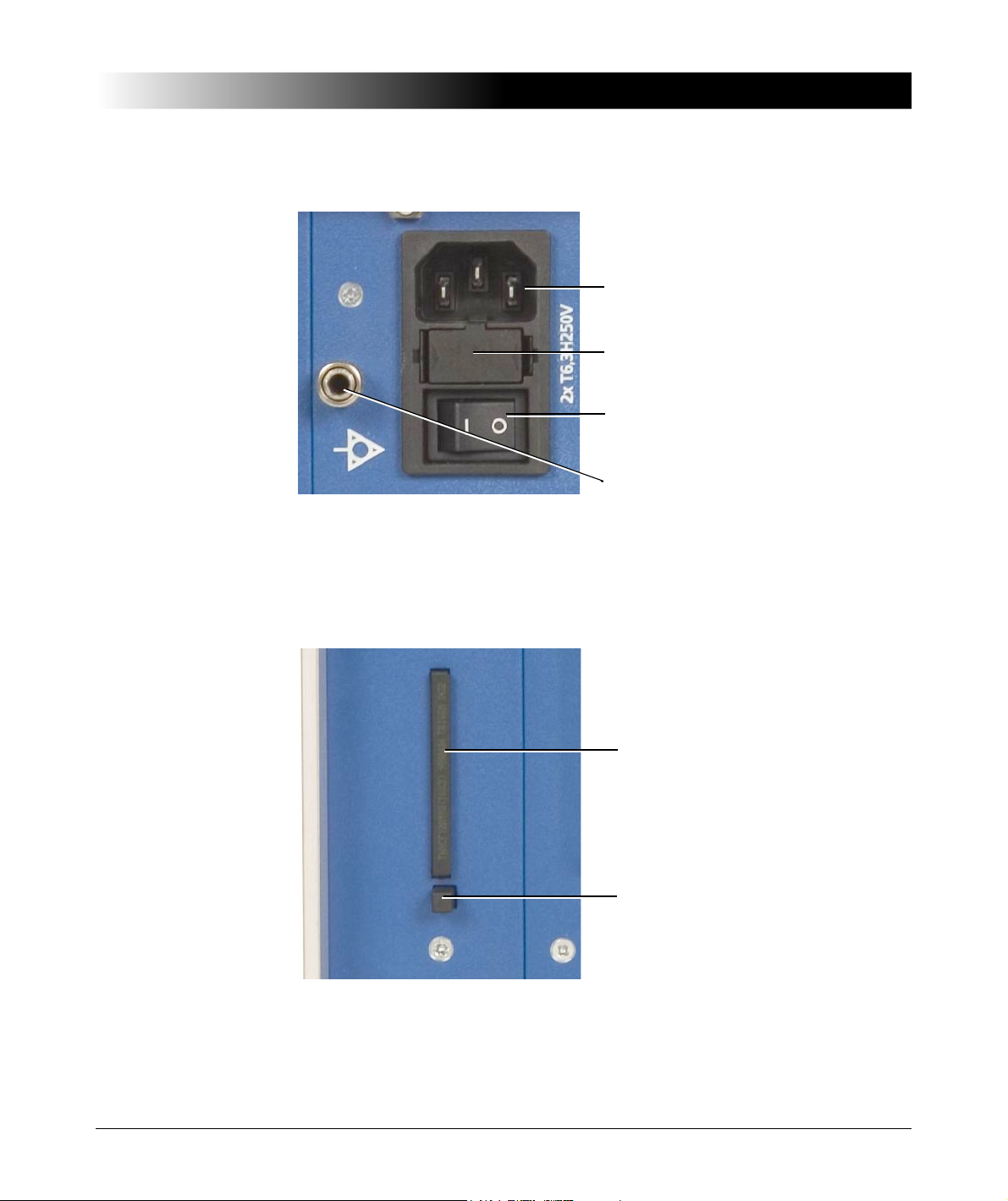
1.2.2 Mains Connection Unit and Grounding
Mains socket (IEC320)
ON/OFF switch
Grounding terminal
(4mm socket combined with knurled
nut for clamp connection)
Mains fuse: 2 x T6.3 A / 250 V,
high breaking capacity
Compact Flash card
Storage medium for test data.
Eject button
Press to eject the Compact Flash
card.
Figure 1-2 Mains connection unit and grounding terminal
Introduction
1.2.3 Compact Flash Card Slot
Figure 1-3 Compact Flash card slot
13

CT Analyzer User Manual
RS232 interface
USB interface
(type B connector)
1.2.4 Remote Control Interface (PC Connection)
CT Analyzer devices as of serial number JHxxxx or newer are equipped with a
USB interface and a RS232 interface. You can use both interfaces alternatively
to connect the CT Analyzer to a computer.
OMICRON recommends to use the USB interface since communication via USB
is considerably faster than communication via RS232.
14
Figure 1-4 Remote control interface (RS232 and USB)
Since in this case the CT Analyzer provides two alternative interfaces, the user
has to select the interface to be used (or check the selection) in the CT Analyzer
settings before connecting the CT Analyzer. The factory default setting for those
devices is USB.
1. Open the Main Menu on the CT Analyzer and select Settings.
2. In the Setting Menu page, select Remote Interface.
3. In the Select remote interface port page, select the interface actually used
to connect the CT Analyzer to the computer: USB or RS232.
The CT Analyzer will only communicate via the selected interface. It will not be
recognized by the computer if the CT Analyzer settings do not match the
interface used for connection.

Note: Please refer to the following sections for more information:
I/0
Output
Generator output.
AC: 40V
rms
, 5A
rms
DC: 120V, 15A
Sec
Measurement input for secondary side of CT,
150V
AC
max., 500kΩ input impedance
Prim
Measurement input for primary side of CT,
30V
AC
max., 150kΩ input impedance
• Section 2.3 on page 23 for information on how to connect the CT Analyzer to
a PC.
• Chapter 5 on page 59 for general information on how to operate the
CT Analyzer.
• Section 5.7 on page 65 for more detailed information about the
Setting Menu page.
1.2.5 Inputs and Outputs
Warning: While the red LED of the key is flashing, voltage is applied at
the output and the measurement inputs.
Introduction
Figure 1-5 Inputs and outputs of the CT Analyzer
15
CT Analyzer User Manual
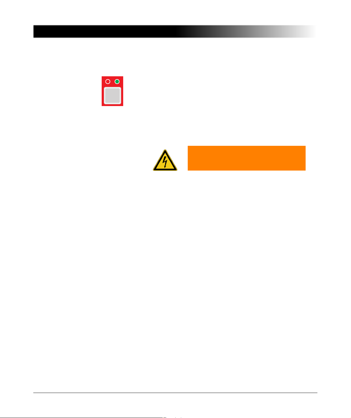
I/0
1.2.6 I/0 Key with Status LEDs
Red LED on the left, green LED on the right.
I/0 key to start the test.
During the boot process after switching the CT Analyzer on, both
LEDs are on. The red LED is switched off when the boot process is
finished and the CT Analyzer is ready for operation.
Green LED on: The CT Analyzer is switched on and ready for
Red LED flashing: Test is running.
Red LED steadily on: Device error.
operation.
Warning: While the red LED is flashing,
voltage is applied at the output and the
measurement inputs.
16

1.2.7 Display with Soft Keys
Card area with tab
Soft key description
fields
Soft keys, labelled by the soft
key description fields
If 3 points are visible in the lowermost soft
key description field (see dashed arrow),
this key can be used to open an additional
set of soft keys
Edit fields
(underlined by
dotted lines)
Status
line
Display field
(not underlined)
A scrollbar is displayed if the content of a
card is too long to be displayed at a time.
Use the up/down cursor keys on the
keyboard to scroll through the card.
Introduction
Figure 1-6 Display with context-dependent soft keys
The following icons may be displayed in the status line:
Remote control. The CT Analyzer is connected to a computer and a
software tool of the CT Analyzer PC Toolset (e.g. the
CTA Remote Excel File Loader) running on that computer has
established connection to the CT Analyzer.
The keyboard on the CT Analyzer is locked until the running test is
finished.
17
CT Analyzer User Manual
1.2.8 Keyboard
Security key. The data measured with the CT Analyzer can be
stored in XML files. Stored files are protected by a security
checksum to prevent the data within these files from being edited.
If the CT Analyzer displays the data of a previously stored test, and
the data in this file are valid, a key is shown in the status line. If the
file data are invalid since someone tried to edit them later, a broken
key is displayed.
Note: When loading older files containing no security checksum, no
security information is shown.
Overload indication. The CT Analyzer could not output the required
test current or take all necessary measurement points due to an
overload.
Multi-ratio CT measurement. Indicates that a multi-ratio CT test
using the optional CT SB2 switch box has been initialized on the
CT Analyzer (here: full tap combination X1-X4).
18
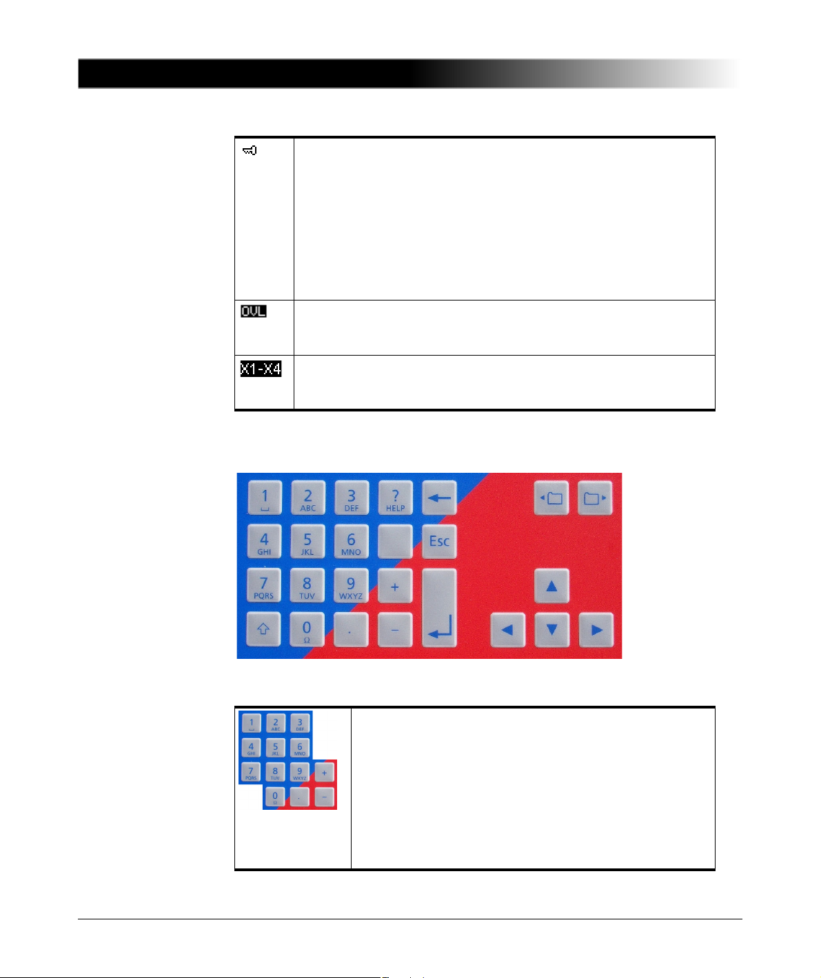
Figure 1-7 Keyboard
Numeric / character keys for entering values and text.
After pressing a key, the status line displays the character
set available for the key. Press the key as often as
required to scroll through the displayed character set. After
1 second or after pressing another key, the character
selected in the status line is entered into the edit field in
the display.
Note: To quickly change between letters and numerics,
hold the button pressed for a second.

Introduction
HELP
?
ESC
Press this key to enter capital letters.
Press this key to display the context-sensitive help system
(see section 5.9 on page 76).
Press this key to delete the character left of the cursor
position.
Press this key to leave an edit field without applying a
change or to leave the edit mode of a card or to go one
level back in the user interface level.
The CT-Object card is the top user interface level.
Pressing this key several times will always bring you back
to the CT-Object card.
Press this key to apply a change for an edit field.
When working in the CT Analyzer file system, use this key
to open a selected folder or to confirm to move back to the
next higher level in the file structure.
Use the card selector keys to display a specific card.
Use the cursor keys to select an edit field in the user
interface or to move the cursor within an edit field.
Use the cursor key to enter the edit mode of a
displayed card.
1.3 License-Depending Functional Scope
The functional scope provided by the CT Analyzer depends on the licenses
actually available on the device.
This User Manual describes the full functional scope provided when the
complete set of licenses is available on the CT Analyzer. A lack of licenses may
primarily result in functional restrictions regarding the selectable standards,
classes, core types and frequencies as well as the availability of individual
measurement functions and/or test cards.
For up-to-date information about the licenses and packages available for the
CT Analyzer please refer to the OMICRON website.
19

CT Analyzer User Manual
1.4 Scope of Delivery, Accessories, Available Licenses
For up-to-date information about the scope of delivery and available accessories
and licenses for the CT Analyzer please refer to the OMICRON website or the
OMICRON office nearest you.
20

Setup and Connection
2 Setup and Connection
2.1 General Safety Rules for Connecting and Operating the CT Analyzer
Observe the following general safety rules when connecting and operating the
CT Analyzer. The safety rules given here are supplemented by further notes and
warnings applicable for specific actions only. Such specific notes and warnings
are given where necessary in this user manual.
• Before putting the CT Analyzer into operation, check the test set for visible
damages.
• When taking the CT Analyzer into operation, make sure that the air slots, the
power switch and the power supply plug at the test set are not obstructed.
• Only use wires with 4mm safety "banana" connectors and plastic housing for
connection to the front panel input/output sockets.
• During the test always connect one terminal of the transformer’s primary side
to protective earth.
Warning: Make sure that the terminals of the test object to be connected to the
CT Analyzer do not carry any voltage potential. During a test, the CT Analyzer
is the only permitted power source for the test object.
Warning: Do not touch the equipment under test or the measurement leads
while the red LED on the CT Analyzer is flashing. Never connect or disconnect
measurement leads while the red LED on the CT Analyzer is flashing.
As long as the red LED is flashing, the output is active and lethal voltages can
occur due to the high energy stored in external inductors.
Warning: Always make sure that the CT Analyzer output is connected to the
correct side of the current transformer according to the wiring instructions given
in sections 2.4 to 2.5 below. Accidentally mixing up the windings can cause lifethreatening voltages within the transformer and/or destroy the connected CT
or the CT Analyzer!
21

CT Analyzer User Manual
Warning: Feeding test voltage to a tap of a multi-ratio CT can cause life-
threatening voltages on other taps with higher ratios. Do not touch these taps!
Using the optional CT SB2 switch box can make the testing of multi-ratio CTs
much safer. If necessary, the CT Analyzer then reduces the test voltage in a
way that the maximum possible voltage within the measurement setup (i.e., the
voltage occurring at the tap combination with the highest ratio) is limited to
200V.
2.2 Setting Up the CT Analyzer
Proceed as follows to set up the CT Analyzer:
1. Make sure to position the CT Analyzer on dry, solid ground.
2. Connect the grounding terminal on the CT Analyzer’s side panel (see section
1.2 on page 12) to protective ground (PE). Use the original cable supplied by
OMICRON or alternatively a solid connection of at least 6mm
point as close as possible to the test object.
3. Connect the CT Analyzer to mains using the supplied power cord. Supply the
CT Analyzer only from a power outlet that is equipped with protective ground
(PE). An error message (901) appears if the PE connection is defective or if
the power supply has no galvanic connection to ground.
2
. Use a ground
22
Warning: The error message 901 is a safety relevant message! This
message may appear if protective ground or equipotential ground is not
connected properly or if the power supply does not have galvanic
connection to ground, which can be the case in very special grid
applications or if the CT Analyzer is supplied by a generator or an isolating
transformer. For safe operation always make sure that protective ground
and equipotential ground are connected properly.
4. Connect the equipment under test according to the instructions given in this
manual. Refer to sections 2.4 and 2.5 for detailed descriptions how to
connect the CT Analyzer for a specific measurement and/or application.

Setup and Connection
to PC
USB A/B
CT Analyzer settings:
Main Menu -> Settings ->
Remote Interface -> USB
CT Analyzer settings:
Main Menu -> Settings ->
Remote Interface -> RS232
to PC
RS232
(crossover)
RS232/USB
adapter
CT Analyzer settings:
Main Menu -> Settings ->
Remote Interface -> RS232
to PC
RS232
(crossover)
2.3 Connecting the CT Analyzer to a PC (optional)
CT Analyzer devices as of serial number JHxxxx or newer are equipped with a
USB interface and a RS232 interface. You can use both interfaces alternatively
to connect the CT Analyzer to a computer.
Proceed as follows to connect the CT Analyzer to a PC:
1. Select the interface to be used (or check the selection) in the CT Analyzer
settings:
– Open the Main Menu on the CT Analyzer and select Settings.
– In the Setting Menu page, select Remote Interface.
– In the Select remote interface port page, select the interface actually
used to connect the CT Analyzer to the computer: USB or RS232.
2. Connect the CT Analyzer to the PC using a RS232 cable or a USB cable as
shown in the following figure.
CT Analyzer connected via USB
CT Analyzer connected via RS232 interface and a RS232/USB adapter on
the PC side
CT Analyzer connected via RS232 interface
Figure 2-1 Connecting the CT Analyzer to a PC
23

CT Analyzer User Manual
2.4 Connection for Usual Applications
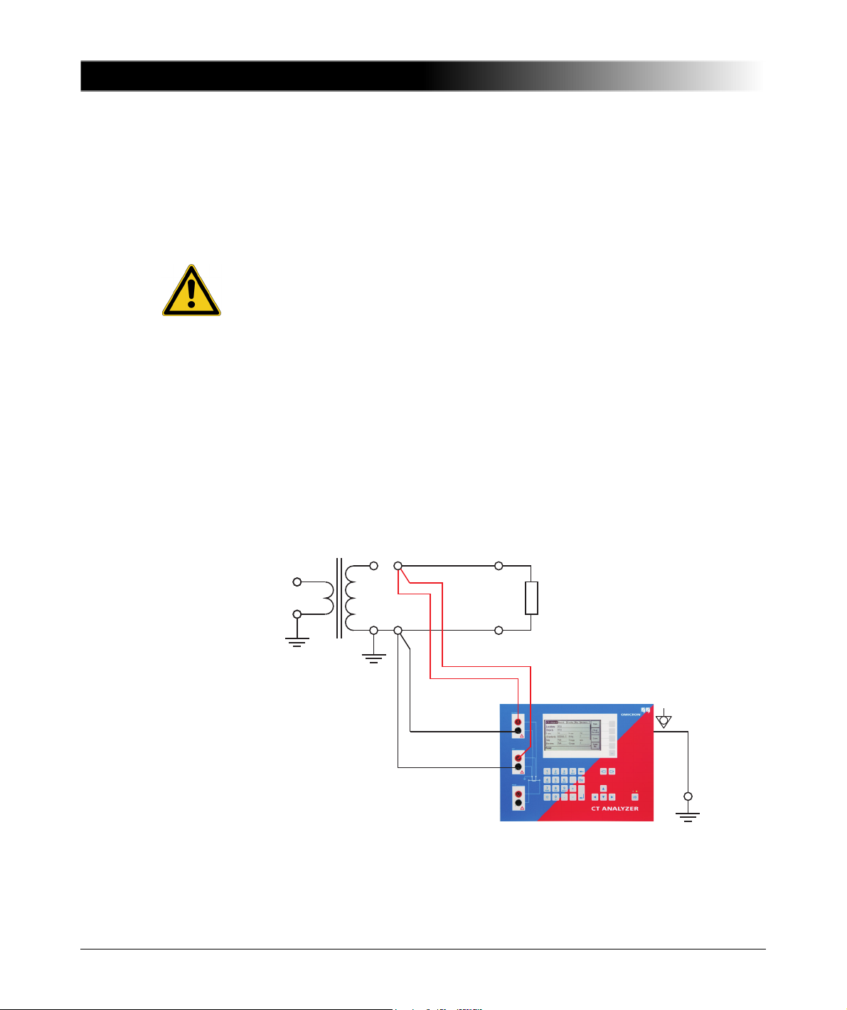
2.4.1 Wiring for a CT Test
This section shows the basic wiring of the CT Analyzer for a CT test.
Observe the general safety rules in section 2.1 on page 21 and the hints and
instructions for improving the quality of the measurement results given in section
2.7 on page 42.
Warning: Feeding test voltage to a tap of a multi-ratio CT can cause lifethreatening voltages on other taps with higher ratios. Do not touch these taps!
Caution: The grounded terminal on the secondary side of the CT always has
to be connected to the black sockets of input "Sec" and the "Output" of the
CT Analyzer. Connecting the red sockets of the CT Analyzer to PE can result
in incorrect measurement and/or cause an automatic abortion of the
measurement with an error message.
Caution: If it is necessary to use clamps for the connection of the
measurement leads to the secondary side of the test object, always use the
4-wire connection technique as described in section 2.7.1 on page 42 in order
to avoid measurement errors.
For a CT test, connect the CT Analyzer as shown in Figure 2-2:
1. Make sure that the primary side of the CT is connected to PE on one side and
open on the other side.
Caution: It is absolutely important to avoid coupling of interferences into the
primary circuit during measurement. Therefore, connect the side of the primary
circuit that is able to receive more interferences to PE (e.g. the side with the
longer line length). The ungrounded side should be the side that receives less
interferences (refer to Figure 2-2).
2. Disconnect the hot side of all secondary windings of the CT in order to
remove any load from the CT. Every kind of load remaining on the secondary
side of the CT during measurement leads to incorrect measurement results
or error messages.
3. Connect the black socket of CT Analyzer input "Prim" to the grounded side
of the CT’s primary circuit and the red socket of this input to the open
(ungrounded) side.
24

Setup and Connection
Utility line
Prevent coupling of interferences into the primary circuit (e.g. by
disconnecting the utility line, switching off the breaker, etc).
Coupling of interferences into the ungrounded connection
influences the measurement results.
The side that is able
to receive more
interferences has to
be connected to PE.
4. Connect the black "Output" socket and the black socket of input "Sec" of the
CT Analyzer to that terminal on the secondary side of the CT that is
connected to PE.
5. Connect the red "Output" socket and the red socket of input "Sec" of the
CT Analyzer to the other (ungrounded) terminal on the secondary side of the
CT.
Figure 2-2 Basic wiring for a CT test
Note: The CT may make humming or buzzing noises of varying frequency
during the CT test. This is completely normal and does not indicate a defective
CT.
25
CT Analyzer User Manual
CT Burden
2.4.2 Wiring for a Burden Test
For a burden test, connect the CT Analyzer as shown in Figure 2-3. Observe the
general safety rules in section 2.1 on page 21.
1. Open the connection line to the ungrounded side of the CT (refer to Figure
2-3).
Caution: If you do not disconnect the CT for the burden test, the
CT Analyzer measures the parallel impedance of the burden and the CT
winding instead of the burden itself. Although in many cases the impedance
of the CT is many times higher than the burden impedance, this will cause a
measuring error.
The CT Analyzer does not perform demagnetization after burden
measurement. Therefore, CT saturation could occur if you do not disconnect
the CT prior to the burden test.
2. Connect the black "Output" socket and the black socket of input "Sec" of the
CT Analyzer to that side of the burden that is connected to PE.
3. Connect the red "Output" socket and the red socket of input "Sec" of the
CT Analyzer to the other (ungrounded) side of the burden.
Figure 2-3 Basic wiring for a burden test
26

Setup and Connection
Utility line Utility line
2.4.3 Wiring for Primary Resistance Measurement
For the primary winding resistance measurement, connect the CT Analyzer as
shown in Figure 2-4. Observe the general safety rules in section 2.1 on page 21.
1. Make sure that the primary side of the CT is connected to PE on one side and
open on the other side.
2. Disconnect the hot side of all secondary windings of the CT in order to
remove any load from the CT. Every kind of load remaining on the secondary
side of the CT during measurement leads to incorrect measurement results
or error messages.
3. Connect the black socket of CT Analyzer input "Prim" to the grounded side
of the CT’s primary winding and the red socket of this input to the open
(ungrounded) side.
4. Connect the black "Output" socket of the CT Analyzer to the grounded side
of the CT’s primary winding and the red "Output" socket to the ungrounded
side of the primary winding.
Figure 2-4 Basic wiring for primary winding resistance measurement
27

CT Analyzer User Manual
Air gap
Position 2
Ratio error measured: +5%
Position 1
Ratio error measured: +0.5%
Position 3
Ratio error measured: -15%
Primary wire
2.5 Connection for Special Applications
2.5.1 Measurement on a Gapped Core
For gapped cores, the position of the primary wire inside the core has a large
influence on the ratio measurement results.
Therefore, in order to obtain correct measurement results, it is very important to
arrange the primary wire during measurement to the same position inside the
core as it is during real operation. Depending on the position of the primary wire
inside the core, the measured ratio can differ by up to 20%.
The figure below shows how the ratio error can differ depending on the position
of the primary wire inside the core.
28
Figure 2-5 Ratio error depending on the position of the primary wire inside
As shown in Figure 2-5, the measured ratio error may differ considerably
depending on the position of the primary wire. Best measurement results are
obtained if the primary wire is positioned exactly in the center of the core. As an
alternative, a copper foil formed to a ring and placed to the inner side of the core
can be used as shown in Figure 2-6.
the gapped core

Setup and Connection
Copper foil
Figure 2-6 Using a copper foil formed to a ring as primary wire
Note: Exact measurement results are only possible if the primary wire is
positioned exactly in the center of the core.
The CT Analyzer does not consider leakage inductances. The leakage
inductances are neglected instead. This way, the CT Analyzer is able to reach a
measurement error of approx. 0.1% for class PR and class TPY CTs and
approx. 0.8% for class TPZ CTs.
2.5.2 Excitation Curve Measurement for an Unwound Iron Core
Using the CT Analyzer it is possible to measure the magnetic properties of an
empty, unwound iron core. For this purpose, it is necessary to apply an "auxiliary
winding" of at least 20 turns to the core.
For this purpose, OMICRON offers a special cable with 23 turns (VEHK0658)
and a special Microsoft Excel template for the required calculations.
Proceed as follows to perform the measurement (refer to Figure 2-7 and Figure
2-8). Observe the general safety rules in section 2.1 on page 21.
1. Apply the "auxiliary winding" cable to the unwound core.
2. Connect the "Output" sockets and input "Sec" of the CT Analyzer to the cable
as shown in Figure 2-7. For cores that require high currents to reach the knee
point, several cables can be cascaded to increase the number of turns, see
Figure 2-8.
3. Start the CTA Remote Excel File Loader with the special Excel template
mentioned above.
4. Enter the iron parameters to the template.
29

CT Analyzer User Manual
Iron core without winding
23 turns auxiliary
winding
Figure 2-7 Excitation curve measurement using one "auxiliary winding"
cable
Figure 2-8 Excitation curve measurement using several cascaded
"auxiliary winding" cables
2.5.3 Measurement on a GIS (SF6) Switch Gear
Proceed as follows to perform measurements on a GIS (SF6) switch gear (refer
to Figure 2-9). Observe the general safety rules in section 2.1 on page 21.
1. Disconnect all utility lines.
2. Open all circuit breakers to the bus bars.
3. Close the earthing switch.
4. Connect one secondary side terminal of the CT to protective earth.
30

Setup and Connection
Utility line
disconnected
100m max.
Gas insulated busbar
Earthing switch
Circuit breaker
3m max.
Burden
Coax measurement cables
5. Connect the secondary side of the CT to the "Output" sockets and input "Sec"
of the CT Analyzer:
• Connect that side of the CT that is connected to PE to the black sockets
of the CT Analyzer.
• Connect that side of the CT that is open to the red sockets of the
CT Analyzer.
6. Connect the primary side of the CT to CT Analyzer input "Prim". Make sure
that the polarity is correct (same colors on same polarity).
Figure 2-9 Measurement on a GIS (SF6) switch gear
31

CT Analyzer User Manual
2.5.4 Measurement on Bushing-Type CTs
Measurement on a Bushing-Type CT
Proceed as follows to perform measurements on a bushing-type CT (refer to
Figure 2-10). Observe the general safety rules in section 2.1 on page 21.
1. Disconnect all utility lines from the transformer (i.e., isolate the transformer
from the energized power system).
2. Connect all transformer terminals that are not used for measurement (in this
example H2 and H3) to protective earth (PE) in order to minimize the external
disturbances. External disturbances can influence the measurement results
because the bushings are acting as an antenna.
3. Connect terminal H0 to protective earth.
4. Connect one secondary side terminal of the CT to protective earth.
5. Connect the secondary side of the CT to the "Output" sockets and the "Sec"
sockets of the CT Analyzer:
• Connect that side of the CT that is connected to PE to the black sockets
of the CT Analyzer.
• Connect that side of the CT that is open to the red sockets of the
CT Analyzer.
6. Connect the primary side of the CT to CT Analyzer input "Prim". Make sure
that the polarity is correct (same colors on same polarity).
7. Short-circuit and ground the free winding on the measured transformer leg to
reduce the impedance of the winding that is connected in series to the
primary side of the CT. The input impedance of CT Analyzer input "Prim" is
only approx. 330k
winding of that leg is short-circuited.
8. If the transformer has a tap changer installed, the position of the tap changer
should be changed to a position where the regulation winding is completely
bridged in order to ensure that the regulation winding cannot act as a voltage
divider together with the main winding of the transformer.
Ω and can thus influence the measurement results, if no
32

Setup and Connection
H0
(Mp)
(N)
H3
(C)
(W)
H2
(B)
(V)
H1
(A)
(U)
CT
Coax measurement cables
Figure 2-10 Measurement on a bushing-type CT
Note: Primary terminal H1 must be open. Otherwise the primary side is shorted
and the CT Analyzer cannot obtain proper results.
Measurement on a Y (Wye) Winding Transformer
For measurements on current transformers in Y-connected transformer
windings it has to be assured that the main impedance of the transformer does
not influence the measurement results.
The CT Analyzer has an input impedance of approx. 330kΩ. This measurement
impedance can be low enough to influence the measurement results. In order to
prevent any influence of the CT Analyzer's input impedance to the measurement
results, the transformer winding at the same leg should be short-circuited. Shortcircuiting the windings on all legs of the transformer is even better.
Furthermore, all bushing terminals that are not connected to the CT Analyzer
should be connected to protective earth in order to prevent influence of external
disturbances (see Figure 2-11).
33

CT Analyzer User Manual
Figure 2-11 Measurement on a Y winding transformer
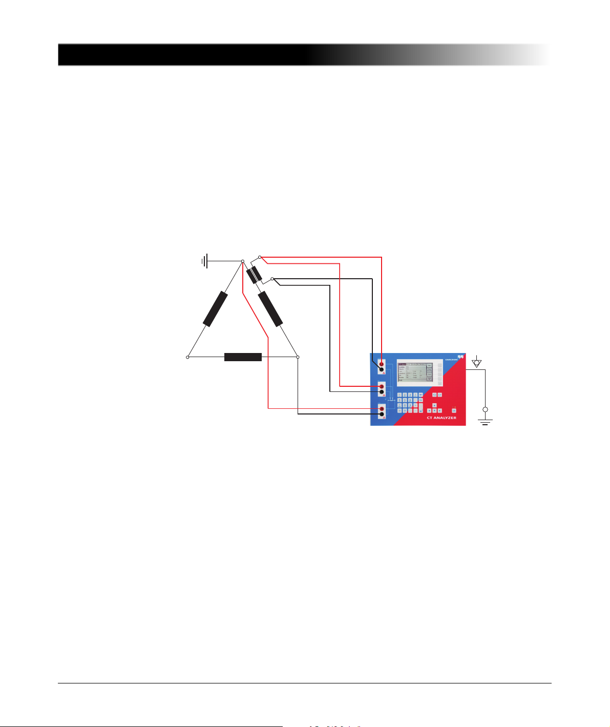
Measurement on a Δ (Delta) Winding Transformer
CTs outside the delta winding
For CTs that are located in the bushing outside of the delta winding (Figure
2-12), no delta compensation is needed.
In this case, only two parallel transformer windings are connected in series to
the CT. This connection method provides least possible influence to the
measurement result for the winding resistance of the CT.
The Y winding and the remaining windings of the power transformer's delta
winding are short-circuited to avoid influence of the induced flux of the power
transformer's core to the measurement.
34

Setup and Connection
Figure 2-12 Bushing-type CT outside the delta winding power transformer
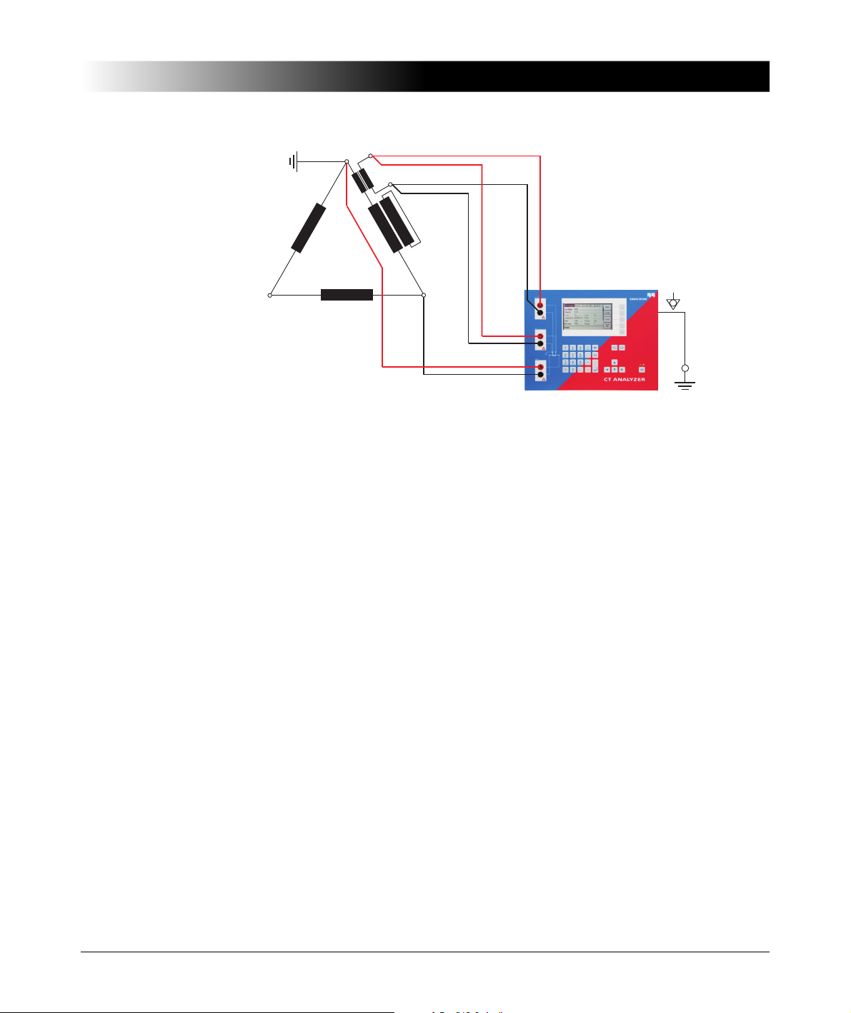
CTs inside the delta winding
For CTs that are integrated in the delta winding of the transformer, it is not
possible to read the CT ratio directly since the delta winding acts as a voltage
divider. In order to obtain the correct CT ratio, the ratio value determined by the
CT Analyzer has to be corrected.
For this purpose, the CT Analyzer provides a "Delta Compensation" field on the
CT- Object card where you can select the delta compensation factor depending
on the bushing terminals that are used for primary signal measurement.
Figure 2-13 Setting the delta compensation on the CT-Object card
35
CT Analyzer User Manual
L2
L3
L1
If it is possible to short-circuit the transformer winding at the same leg as the
primary measurement is done (see Figure 2-15), the measurement should be
performed with the winding short-circuited. In this case, no delta compensation
is required since the voltage induced on the transformer’s secondary winding is
zero and thus the voltage induced on the primary side of the transformer is also
zero.
For the measurement setup shown in Figure 2-14, the delta compensation factor
on the CT-Object card has to be set to "Ratio 2/3" (see Figure 2-13).
If input "Prim" is connected between L1 and L2, the delta compensation has to
be set to "Ratio 1/3".
Figure 2-14 Measurement setup for delta compensation "Ratio 2/3"
In the configuration shown in Figure 2-15, no delta compensation is required
since the main winding of the power transformer is short-circuited on the other
side. This avoids the induction of flux in the main winding of the power
transformer that could influence the measurement results.
36
Setup and Connection
L2
L3
L1
Figure 2-15 Measurement setup for delta compensation "Ratio 1"
37

CT Analyzer User Manual
a
n
A
N
2.5.5 VT Ratio Measurement Using QuickTest
To measure the ratio of VTs using the CT Analyzer, you can either use the
Quick Test function of the CT Analyzer (see chapter 8 on page 135) or the
CTA QuickTest PC tool which is part of the CT Analyzer PC Toolset.
Observe the general safety rules in section 2.1 on page 21.
Warning: For VT ratio measurement using the Quick Test feature, the
CT Analyzer output has to be connected to the primary side of the VT.
Connecting the CT Analyzer output to the secondary side of the VT by mistake
will cause hazardous voltages on the primary side!
For VT ratio measurements using Quick Test, connect the CT Analyzer as
shown in Figure 2-16. For a detailed description on how to perform such
measurements, please refer to section 8.7 on page 151.
1. Connect the "Output" sockets and input "Sec" of the CT Analyzer to the
primary side of the VT.
2. Connect input "Prim" of the CT Analyzer to the secondary winding of the VT.
Figure 2-16 Connecting the VT for ratio measurement using the
CT Analyzer
38

Setup and Connection
a
n
A
N
2.5.6 VT Winding Resistance Measurement Using QuickTest
To measure the winding resistance of VTs using the CT Analyzer, you can either
use the Quick Test function of the CT Analyzer (see chapter 8 on page 135) or
the CTA QuickTest PC tool which is part of the CT Analyzer PC Toolset.
Observe the general safety rules in section 2.1 on page 21.
For VT winding resistance measurements using Quick Test, connect the
CT Analyzer as shown in Figure 2-17. For a detailed description on how to
perform such measurements, please refer to section 8.8 on page 154.
Connect the "Output" sockets and input "Sec" of the CT Analyzer to the winding
to be measured.
Figure 2-17 Connecting the VT for winding resistance measurement using
the CT Analyzer
2.5.7 Polarity Check Using QuickTest and the CPOL Polarity Checker
Observe the general safety rules in section 2.1 on page 21.
For the polarity check using Quick Test, connect the CT Analyzer as shown in
Figure 2-18. For a detailed description on how to perform the polarity check,
please refer to section 8.5 on page 145.
1. Ensure that the ungrounded side of the CT winding is not connected to the
wiring to be checked.
2. Connect the black "Output" socket and the black socket of input "Sec" of the
CT Analyzer to that side of the burden that is connected to PE.
39

CT Analyzer User Manual
CT
Burden
CPOLCPOL
3. Connect the red "Output" socket and the red socket of input "Sec" of the
CT Analyzer to the other (ungrounded) side of the burden.
Figure 2-18 Wiring for a polarity check of the burden wiring using Quick Test
and the CPOL polarity checker
Note: The CT Analyzer measures the voltage of the injected signal using input
"Sec". Therefore, you should always connect this input when using the Polarity
Check measurement type. The higher the resistance of the wiring checked (i.e.,
the burden wiring) or the current amplitude set on the CT Analyzer, the higher
the terminal voltage generated by this current!
40

2.6 Disconnection
Proceed as follows to disconnect the CT Analyzer:
1. Wait until the red LED on the CT Analyzer is off.
Warning: Never disconnect measurement leads while the red LED on the
CT Analyzer is flashing. As long as the red LED is flashing, the output is active
and lethal voltages can occur due to the high energy stored in external
inductors.
2. Disconnect the measurement leads starting at the CT Analyzer.
Setup and Connection
41
CT Analyzer User Manual
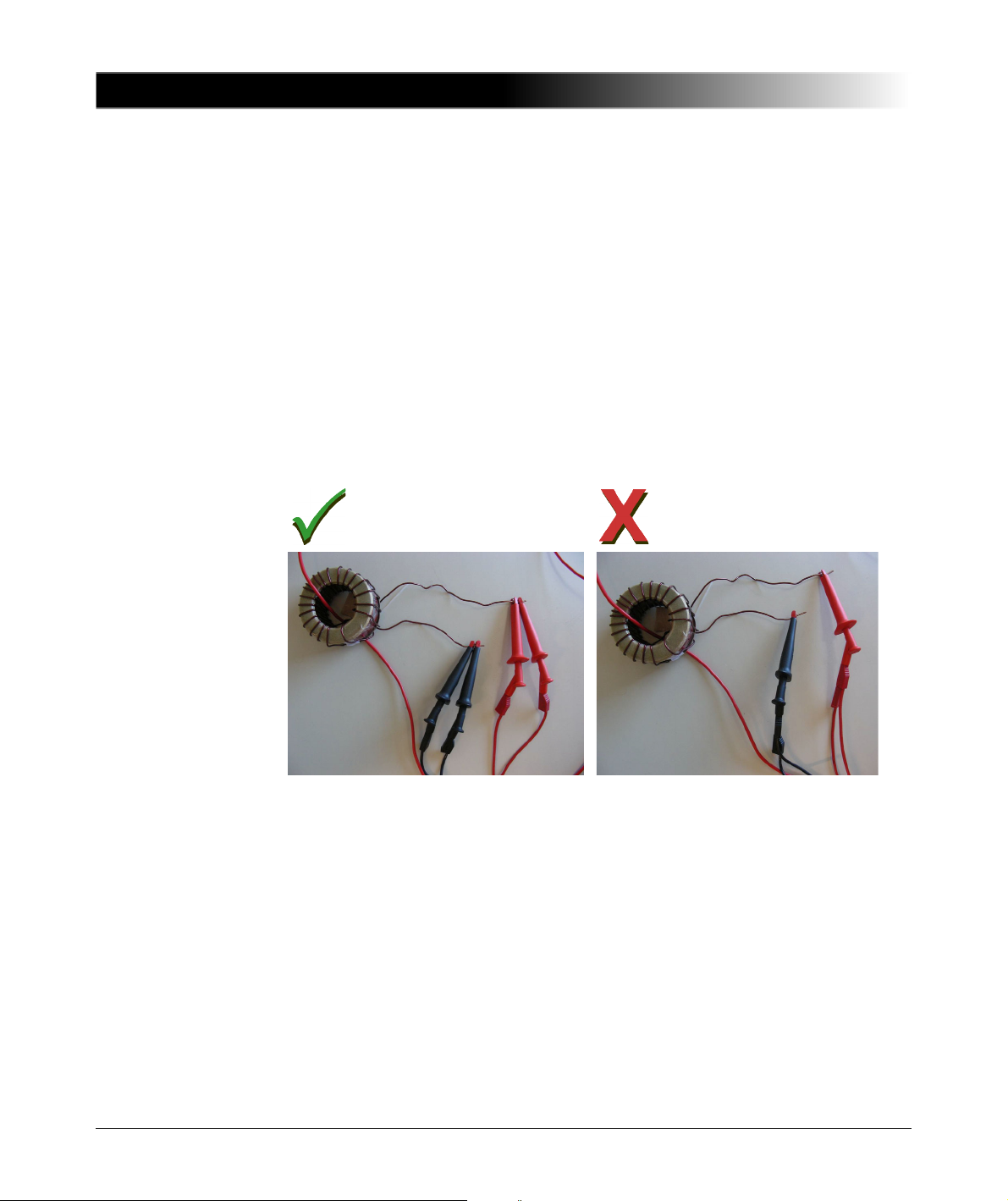
The measurement leads from the
"Output" sockets and input "Sec" of
the CT Analyzer are connected to the
test object via separate clamps.
One clamp is used for each
measurement lead! Correct!
Separate measurement leads are
used for the "Output" sockets and
input "Sec" of the CT Analyzer, but
the measurement leads are
connected to the test object via a
common clamp.
Two measurement leads use one
single clamp! Do not use!
Do not use!
OK
4-wire connection 2-wire connection
2.7 Improving the Quality of Measurement Results
2.7.1 4-Wire Measurement vs. 2-Wire Measurement
If the secondary side of the test object does not provide screw terminals for
connecting the delivered terminal adapters or banana sockets to insert the
measurement leads directly, and it is therefore necessary to use clamps (e.g.
crocodile clamps or Kelvin clamps) for the connection of the measurement
leads, always use the 4-wire connection technique as described below.
Otherwise, the possibly existing contact resistance of the clamps could
affect the measurement results, i.e., the CT Analyzer possibly delivers
incorrect measurement results.
Both connection techniques are shown in the following figure.
42
Figure 2-19 Demonstration of 2-wire and 4-wire connection technique

2.7.2 Noise Reduction Techniques
For proper test results it is important to consider the following:
• If possible, disconnect both primary terminals of the CT from the utility lines.
• If possible, always use the original coax measurement cables delivered by
OMICRON. If it is necessary to use loose single-wire measurement cables,
twist the wires to a twisted-pair line. Avoid open loops consisting of individual
single-wire measurement cables in order to prevent interference voltages
caused by magnetic fields.
• Connect one terminal of the CT’s primary side to protective earth. If it is not
possible to disconnect the utility lines from both primary terminals, connect
that side of the primary circuit that is able to receive more interferences to PE
(the primary side that is still connected to the utility lines or the side with the
longer line length, respectively). The ungrounded side should be the side that
receives less interferences.
• When testing a CT in a utility, take care that one side of the CT is connected
to PE and at least the ungrounded terminal is disconnected from all utility
lines.
Refer to Figure 2-20.
Setup and Connection
Note: Do not connect both primary terminals to PE! This would cause
incorrect measurement results. Connecting both primary terminals to PE has the
same effect as a short-circuit in the CT.
43

CT Analyzer User Manual
Utility line
Utility line
Connection required if
secondary side
terminal cannot be
disconnected
Burden
Use coax measurement cables!
Figure 2-20 Noise reduction for CT measurement
44

Short Guide for Running a CT Test
3 Short Guide for Running a CT Test
This chapter provides a short guide for running a CT test using the CT Analyzer.
This short guide is intended as an overview of a complete test procedure. For
more detailed information, please refer to chapter 4 on page 49.
This short guide does not consider the residual magnetism measurement (see
section 6.4 on page 102) and does not use the guesser function of the
CT Analyzer (see chapter 7 on page 131).
When working with the CT Analyzer, always observe the safety rules given in
section 2.1 on page 21.
Note: The CT may make humming or buzzing noises of varying frequency
during the CT test. This is completely normal and does not indicate a defective
CT.
Warning: Do not touch the equipment under test or the measurement leads
while the red LED on the CT Analyzer is flashing. Never connect or disconnect
measurement leads while the red LED on the CT Analyzer is flashing.
As long as the red LED is flashing, the output is active and lethal voltages can
occur due to the high energy stored in external inductors.
Warning: Always make sure that the CT Analyzer output is connected to the
correct side of the current transformer according to the wiring instructions given
in sections 2.4 and 2.5. Accidentally mixing up the windings can cause lifethreatening voltages within the transformer and/or destroy the connected CT
or the CT Analyzer!
Warning: Feeding test voltage to a tap of a multi-ratio CT can cause lifethreatening voltages on other taps with higher ratios. Do not touch these taps!
45
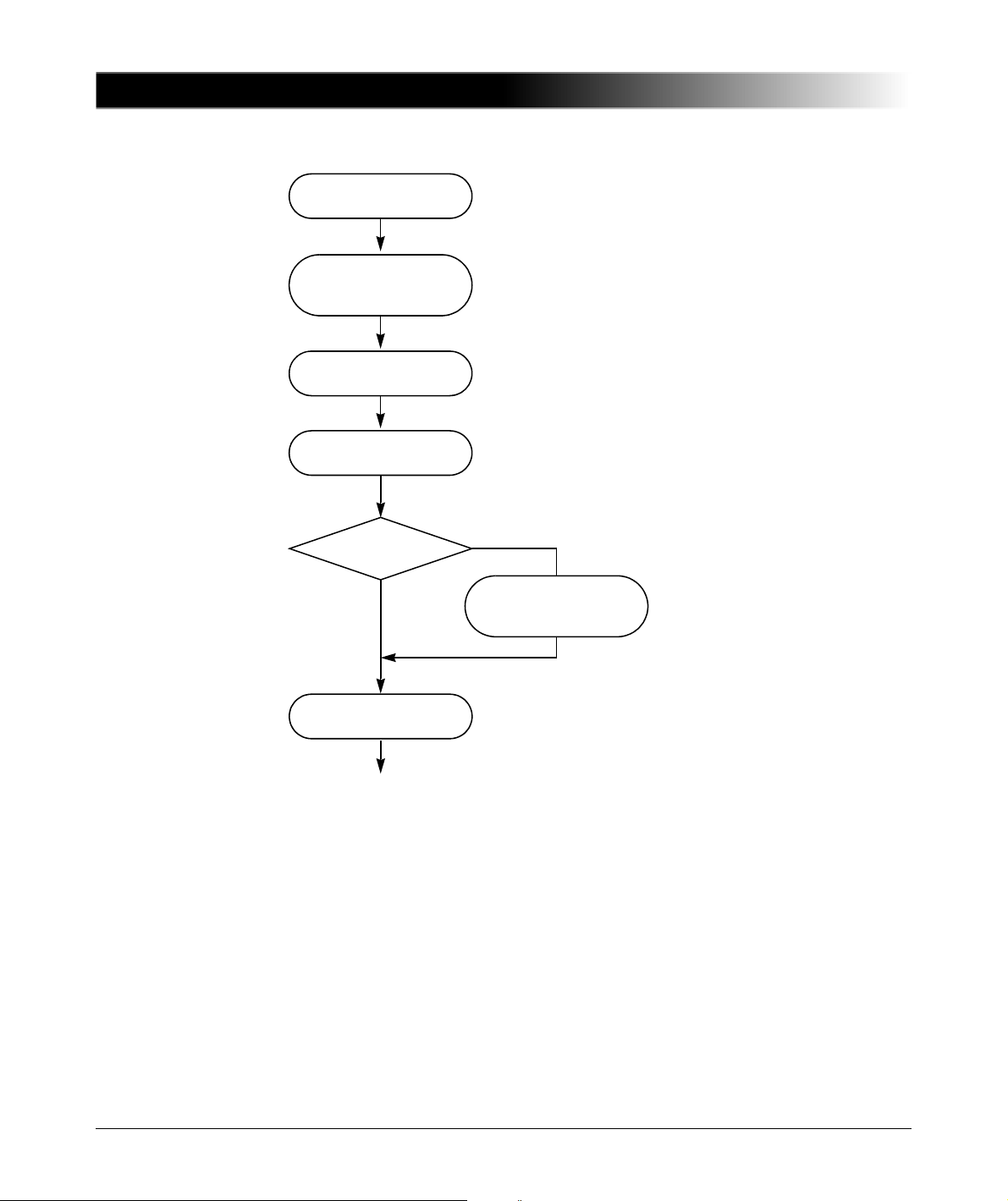
CT Analyzer User Manual
Set up the CT Analyzer
-> 2.2 on page 22
Switch the CT Analyzer on and
display the CT-Object card
-> 4.2 on page 50
Select test cards
-> 4.2, step 2. on page 50
Enter CT name plate data
-> 4.2, step 3. on page 51
Burden test card
enabled?
Select test current for
burden test
-> 4.2, step 4. on page 52
Start test
-> 4.3, step 1. on page 52
see next page
Yes
No
46

Test execution:
Burden test
Test finished message
-> 4.3, step 11. on page 54
Disconnect or perform new test
-> 4.5 on page 57
Burden test card
enabled?
Connect CT Analyzer
for burden test
-> 2.4.2 on page 26
Start Test
soft key
Skip Test
soft key
Cancel Test
soft key
Connect CT Analyzer
for CT test
-> 2.4.1 on page 24
Prim.
Winding Resistance
measurement
enabled?
Connect CT Analyzer for
primary winding resistance
measurement
-> 2.4.3 on page 27
Start Test
soft key
Skip Test
soft key
Cancel Test
soft key
View results
-> 4.4 on page 55
Start Test
soft key
Skip Test
soft key
Cancel Test
soft key
Test execution:
CT test
from previous page
Yes
No
Yes
No
Test execution:
Prim. winding resistance
measurement
Residual Magnetism
measurement if enabled
-> 6.4 on page 102
Short Guide for Running a CT Test
47

CT Analyzer User Manual
48
Running a CT Test (Detailed)
4 Running a CT Test (Detailed)
This chapter provides a detailed description how to run a CT test using the
CT Analyzer. Follow the sections 4.1 to 4.5 in the given order.
The example CT test described below does not use the guesser function, which
is an aid for the user to find out single unknown name plate data of a CT, for
example if parts of the CT’s name plate are unreadable. For detailed information
about the guesser function, please refer to chapter 7 on page 131.
When working with the CT Analyzer, always observe the safety rules given in
section 2.1 on page 21.
Note: The CT may make humming or buzzing noises of varying frequency
during the CT test. This is completely normal and does not indicate a defective
CT.
Warning: Do not touch the equipment under test or the measurement leads
while the red LED on the CT Analyzer is flashing. Never connect or disconnect
measurement leads while the red LED on the CT Analyzer is flashing.
As long as the red LED is flashing, the output is active and lethal voltages can
occur due to the high energy stored in external inductors.
Warning: Always make sure that the CT Analyzer output is connected to the
correct side of the current transformer according to the wiring instructions given
in sections 2.4 and 2.5. Accidentally mixing up the windings can cause lifethreatening voltages within the transformer and/or destroy the connected CT
or the CT Analyzer!
Warning: Feeding test voltage to a tap of a multi-ratio CT can cause lifethreatening voltages on other taps with higher ratios. Do not touch these taps!
49

CT Analyzer User Manual
I/0
4.1 Setting Up the CT Analyzer
1. Set up the CT Analyzer as described in section 2.2 on page 22.
4.2 Preparing and Configuring the Test
1. Proceed as follows to display the CT-Object card with a new CT test.
If the CT Analyzer is already switched on:
– If necessary, display the CT-Object card and then press the Main soft key
to display the main menu.
– In the main menu, select "New CT Test" and press the OK soft key to
initialize a new CT test.
– The display shows the CT-Object card, ready to start a test.
If the CT Analyzer is switched off:
– Switch the CT Analyzer on.
– After the boot process is finished, the green LED is on and the red LED is
off.
– The display shows the CT-Object card, ready to start a test.
2. For reasons of simplicity, we do not want to perform a residual magnetism
measurement in our example CT test described here. Press the Select
Cards soft key in the CT-Object card to open the Select Cards page. Check,
and if necessary make the following test card selection (see Figure 4-1):
The following test cards are required: CT-Object, Burden, Primary Winding
Resistance, Secondary Winding Resistance, Excitation, Ratio and
Assessment.
The Residual Magnetism test card is not required. Deselect it if necessary.
Figure 4-1 Select Cards page
When finished, press the Back soft key to return to the CT-Object card.
50

Running a CT Test (Detailed)
3. Enter the CT name plate data listed in the table below to the CT-Object card
(see Figure 4-2).
Figure 4-2 CT-Object card with name plate data entered
I-pn Rated primary current of the CT.
I-sn Rated secondary current of the CT.
Standard Standard to be used for the CT test and the test assessment.
P/M CT type. Set "P" for a protection CT or "M" for a metering CT.
Class Rated accuracy class of the CT. This field becomes available
after selecting the CT type (protection CT or metering CT).
VA Rated power of the CT.
Note: For protection CTs of the IEEE C57.13 classes C, K
and T, the VA parameter is not available. Enter the rated
secondary terminal voltage V
instead (see also "Specific
b
parameters and settings displayed for IEEE C57.13
protection CTs" on page 98).
Note: Depending on the selected standard and CT type, other or further CT
data may be necessary for a correct assessment. If the "Check "*" settings
before start" option is enabled in the default test settings (see section
5.7.3 on page 70), all parameters that are required for assessment are
marked by a star "*" in the CT-Object card. In this case, no automatic
assessment will be available if you do not enter data for one or more
parameters marked by a star "*" (see section 6.2.3 on page 82).
51

CT Analyzer User Manual
I/0
I/0
?
4. If you enabled the Burden test card in step 2., display the Burden card and
specify the test current for the burden measurement. Use the default test
current derived from the I
a test current of your choice to the "I-test" parameter.
Figure 4-3 Defining the test current in the Burden card
previously entered in the CT-Object card or enter
sn
4.3 Running the Automatic Test and Connecting the CT Analyzer
1. Start the test by pressing the key. The red LED flashes to indicate that
the CT test is running.
2. If you enabled the Burden test card in section 4.2, step 2. on page 50 a
message is displayed, asking you to change the wiring for the burden test.
Connect the burden as described in chapter 2.
– Make sure that the red LED on the CT Analyzer is off.
– Refer to section 2.4.2 on page 26 for detailed information on how to
connect the CT Analyzer for the burden test.
– You can display the connection diagram by pressing the key while
the wiring check message is displayed.
Figure 4-4 Burden test: Wiring check message (left) and wiring diagram
(right)
3. Press the Start Test soft key to execute the automatic burden test.
Note: If you do not want to perform the burden test, press Skip Test to skip
the burden test and continue with the next test step or Cancel Test to abort
the complete test.
52

Running a CT Test (Detailed)
I/0
?
?
Note: If the "Continuous burden measurement" option is enabled in the
Settings (see section 5.7.3 on page 70), the burden test has to be stopped
manually by pressing the key.
4. If you enabled the Primary Winding Resistance test card in section 4.2,
step 2. on page 50, a message is displayed, asking you to change the wiring
for the primary winding resistance measurement. Connect the primary
winding of the CT as described in chapter 2.
– Make sure that the red LED on the CT Analyzer is off.
– Refer to section 2.4.3 on page 27 for detailed information on how to
connect the CT Analyzer for the primary resistance measurement.
– You can display the connection diagram by pressing the key while
the wiring check message is displayed.
Figure 4-5 Primary winding resistance measurement: Wiring check
message (left) and wiring diagram (right)
5. Press the Start Test soft key to execute the automatic primary winding
resistance measurement.
Note: If you do not want to perform the primary winding resistance
measurement, press Skip Test to skip the primary winding resistance
measurement and continue with the CT test or Cancel Test to abort the
complete test.
6. A message is displayed asking you to change the wiring for the CT test.
Connect the CT to the CT Analyzer as described in chapter 2.
– Make sure that the red LED on the CT Analyzer is off.
– Refer to section 2.4.1 on page 24 for detailed information on how to
connect the CT Analyzer for the CT test.
– Be sure that the polarity of all wires is correct.
– You can display the connection diagram by pressing the key while
the wiring check message is displayed.
Note: If you do not want to execute the CT test, press the Skip Test soft key
instead of changing the wiring. This will skip the CT test and immediately
perform the demagnetization cycle to finish the test.
53

CT Analyzer User Manual
I/0
7. Press the Start Test soft key to execute the automatic CT test.
8. Automatic test step 1: CT resistance measurement
9. Automatic test step 2: Determination of the excitation characteristic
Figure 4-6 CT test: Wiring check message (left) and wiring diagram
(right)
Note: If you do not want to perform the CT test, press Skip Test to skip the
CT test or Cancel Test to abort the complete test.
The CT Analyzer measures the secondary winding resistance of the CT.
The CT Analyzer measures the excitation curve and determines the knee
point and other important CT data.
10.Automatic test step 3: Ratio measurement
The CT Analyzer then measures the current ratio error, the phase error, the
composite error and the polarity. The CT Analyzer calculates the ratio error
for the operating burden (parameter "Burden" in the CT-Object card) and the
nominal burden (parameter "VA" in the CT-Object card).
11."Test finished" message
When the test is over, the red LED stops flashing and the green LED is on.
The CT Analyzer displays a "Test finished" message showing the status of
the test execution and the overall test assessment (see Figure 4-7).
Press any key on the keyboard to close this message.
Figure 4-7 Test finished message when the test is over
54
Note: The test results and settings of each test finished with the "Test ok"
status are automatically stored to the file OMICRON\AutoSave\
CTAnalyzer.xml on the Compact Flash card. The existing CTAnalyzer.xml
file is overwritten with each successful test. Tests that could not be finished
successfully or that were aborted by the user are not stored and thus do not
overwrite the existing CTAnalyzer.xml file.
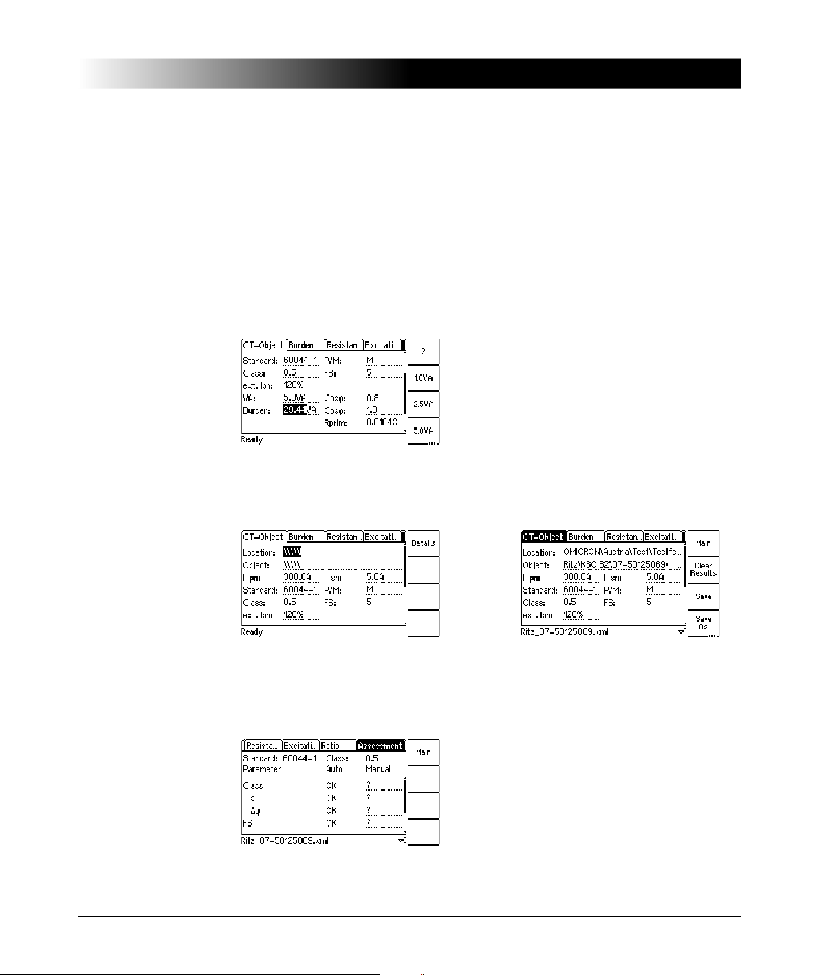
4.4 After the Test is Finished
After the test is finished, the CT-Object card displays the CT data determined
during the test (refer to Figure 4-8).
Figure 4-8 CT-Object card after the test is finished
Running a CT Test (Detailed)
Now, you can enter the "Location" and "Object" details and save the test (use
the cursor keys to scroll within the card and select edit fields).
Figure 4-9 CT-Object card after the test, ready to enter location details
(left) and after saving the test (right)
The assessment of the individual parameters can be viewed on the
Assessment card (Figure 4-10).
Figure 4-10 Assessment card after the test is finished
55

CT Analyzer User Manual
If desired, you can view the individual measurement results acquired during the
test by viewing the Burden, Resistance, Excitation and Ratio cards, as shown
in the following figures 4-11 to 4-14.
Figure 4-11 Burden card with measurement results after the test is finished
Figure 4-12 Resistance card with measurement results after the test is
finished
56
Figure 4-13 Excitation card with measurement results after the test is
finished
Figure 4-14 Ratio error and phase displacement at operating burden after
the test is finished

4.5 Disconnection
After the CT test is finished, disconnect the CT under test from the CT Analyzer.
1. Wait until the red LED on the CT Analyzer is off.
Warning: Never disconnect measurement leads while the red LED on the
CT Analyzer is flashing. As long as the red LED is flashing, the output is active
and lethal voltages can occur due to the high energy stored in external
inductors.
2. Disconnect the measurement leads starting at the CT Analyzer.
Running a CT Test (Detailed)
57

CT Analyzer User Manual
58

Operating and Configuring the CT Analyzer
...
...
1st set of soft keys
Press
2nd set of soft keys
5 Operating and Configuring the
CT Analyzer
5.1 Working in the User Interface
5.1.1 Displaying a Specific Card
To display a specific card, select the card by pressing the card selection keys.
The card’s tab showing the name of the selected card is then highlighted (see
Figure 5-1).
Figure 5-1 CT-Object card selected
5.1.2 Using the Soft Keys
Using the soft keys you can operate the CT Analyzer and change the user
interface level of the software.
The functionality of the soft keys is context-dependent, i.e., the software offers
different functions or selectable sets of parameters depending on the focus (i.e.,
depending on which card or field is highlighted or selected in the user interface).
If the lowermost soft key description field contains 3 points (see Save As in
Figure 5-1), additional soft key functions are available. Then you can switch the
set of displayed soft keys using the key located below the soft keys (see
Figure 5-2).
Figure 5-2 Switching the set of soft keys in the CT-Object card
59

CT Analyzer User Manual
Display field
(selection not
possible)
Edit field
Edit field selected
ESC
ESC
Press the Main soft key in
any test card
-> Main Menu
How to get there:
5.1.3 Editing a Card
To open the edit mode for a displayed card, press the cursor key. The
card’s tab is then no longer highlighted (see Figure 5-3). Use the cursor keys to
move the cursor and to select the desired edit field. Some edit fields have soft
keys assigned. The soft keys available for an edit field are displayed if the field
is selected.
Figure 5-3 Edit field selected in the CT-Object card
Proceed as follows to edit a card:
1. Select the edit field using the cursor keys.
2. Enter or edit the value or text:
– Select an entry offered by the soft keys (if available)
– or enter the value or text using the keyboard and then press the key
to confirm your input or use the key to leave an edit field without
applying and saving the entry.
3. Leave the edit mode either by moving the cursor to the card’s tab using the
cursor key or by pressing the key. The focus is then set to the
card’s tab again (tab highlighted).
5.2 The Main Menu
60
The Main Menu can be opened from any test card by pressing the Main soft key.
The items in the list can be selected using the cursor keys. When an
item is selected (highlighted), the soft keys are labeled with the functions
available for this specific item.
Figure 5-4 Main Menu page
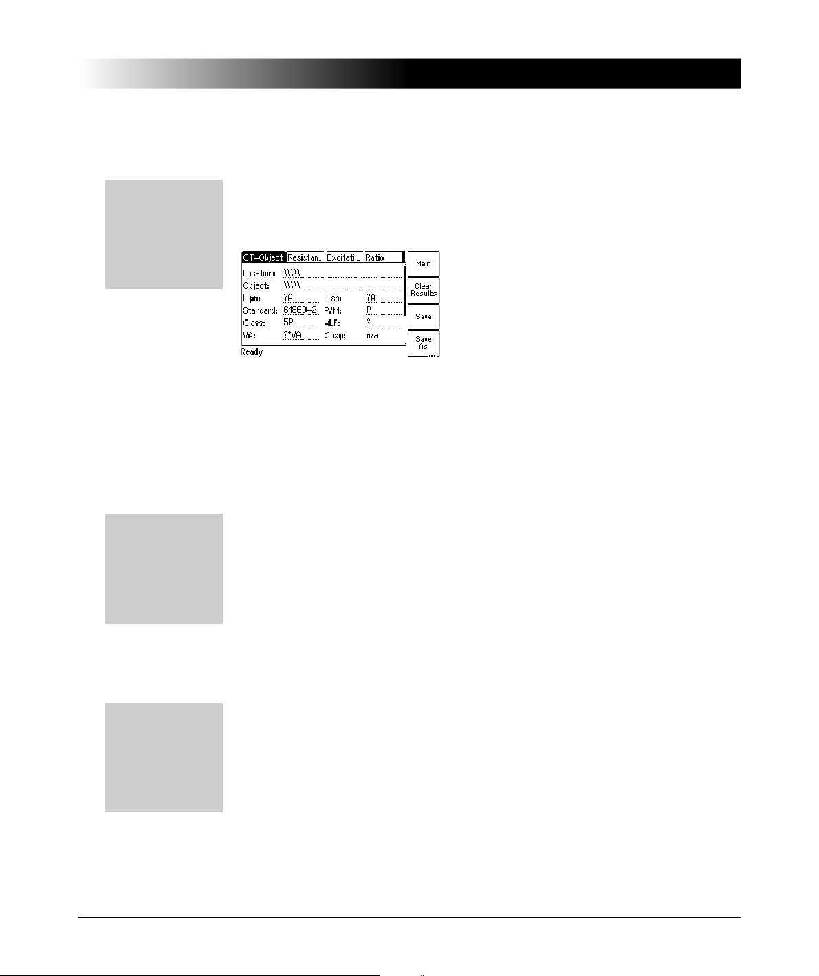
5.3 New CT-Test
Press the Main soft key in
any test card
Main Menu:
- New CT-Test
OK soft key
-> CT-Object card
How to get there:
Press the Main soft key in
any test card
Main Menu:
- New MR-Test
OK soft key
-> CT-Object card
How to get there:
Press the Main soft key in
any test card
Main Menu:
- New Quick-Test
OK soft key
-> CT-Quick card
How to get there:
By selecting "New CT-Test" in the main menu and then pressing the OK soft
key, a new CT test with the default parameter settings is loaded and displayed
in the CT-Object card. Some of the default values can be defined in the default
test settings (see section 5.7 on page 65).
Figure 5-5 CT-Object card with default test settings after initializing a new
Note: For more detailed information about the parameters and fields in the
CT-Object card, please refer to section 6.2 on page 80.
Operating and Configuring the CT Analyzer
CT test
5.4 New MR-Test
Using the "New MR-Test" option in the main menu you can initialize a new multiratio CT test using the optional CT SB2 switch box.
This option is only available if you have purchased a corresponding license. For
more detailed information about multi-ratio CT testing using the CT SB2, please
refer to the CT SB2 User Manual.
5.5 New Quick-Test
Using the "New Quick-Test" option in the main menu you can open the optional
QuickTest feature. With this feature you can use the CT Analyzer as a
multimeter or perform polarity checks using the CPOL polarity checker.
This option is only available if you have purchased a corresponding license. For
more detailed information about QuickTest, please refer to chapter 8 on
page 135.
61

CT Analyzer User Manual
Press the Main soft key in
any test card
Main Menu:
- File Handling
Select soft key
-> File Menu page
How to get there:
5.6 File Handling
5.6.1 Available Functions
62
In the File Menu page you can access all available file operation functions by
selecting the entry using the cursor keys and then pressing the Select
soft key.
Figure 5-6 File Menu page
Load Report Loading an existing report or settings file from the
Compact Flash card.
You can also load a file by pressing the Load soft key in
the CT-Object card.
Save As Saving the current file to the Compact Flash card.
Saving a file is described in detail on page 64.
Delete File Deleting a selected file or folder from the Compact Flash
card.
Only empty folders can be deleted. If you try to delete a
folder still containing files or subfolders, an error
message is displayed.
To select several neighboring files at a time, keep the
key pressed while selecting the files or folders
using the cursor keys.
Rename File Renaming a selected file on the Compact Flash card.
Only files can be renamed. Renaming of folders is not
possible on the CT Analyzer.
Copy / Cut / Paste
File(s)
Copying or cutting a file on the Compact Flash card and
pasting it at another location on the Compact Flash card.
Copying/cutting and pasting a file is described in detail
on page 64.
Format CF card Formatting the Compact Flash card. All data on the
Compact Flash card will be lost!

Note: In the CT Analyzer file system, the root directory can contain a maximum
Press the Main soft key in
any test card
Main Menu:
- File Handling
Select soft key
File Menu:
- Load Report or
- Save As or
- Delete File or
- Rename File or
- Copy File(s) or
- Cut File(s) or
- Paste File(s)
How to get there:
Press the Main soft key in
any test card
Main Menu:
- File Handling
Select soft key
File Menu:
- Save As or
- Paste File(s)
How to get there:
of 240 files and the file name length (incl. the path) is limited to 240 characters.
5.6.2 Working in the File System
After selecting one of the available file operation functions in the File Menu, the
file system card is displayed showing the current path in its title bar and the file
system elements in the card area (refer to Figure 5-7).
Navigating in the file system
• To open a folder, select its entry (see Figure 5-7, left) using the
cursor keys and then press the key.
• To go one level higher in the directory structure, select the "one level higher"
entry and then press the key.
Operating and Configuring the CT Analyzer
Figure 5-7 File system card for loading a report
Creating a new folder
Creating a new folder is only possible for the functions Save As and
Paste File(s) of the File Menu.
To create a new folder in the file system, select Save As or Paste Files(s) in the
file menu and then navigate to the desired location in the file system where you
want to create the new folder. Then press the New Dir soft key. A new folder
with an empty name is created. Enter a name for the folder and press the
key.
Figure 5-8 File system card after creating a new folder
Note: In the CT Analyzer file system, a directory can contain a maximum of 240
files and the maximum file name length is 240 characters. Renaming of folders
is not supported by the CT Analyzer.
63

CT Analyzer User Manual
Press the Main soft key in
any test card
Main Menu:
- File Handling
Select soft key
File Menu:
- Save As
How to get there:
Press the Main soft key in
any test card
Main Menu:
- File Handling
Select soft key
File Menu:
- Copy File(s) or
- Cut File(s)
How to get there:
Saving a file
1. Open the file menu and select Save As.
2. Navigate to the desired folder in the file system where you want to save the
Note: The test results and settings of each test finished with the "Test ok" status
are automatically stored to the file OMICRON\AutoSave\CTAnalyzer.xml on
the Compact Flash card. The existing CTAnalyzer.xml file is overwritten with
each successful test. Tests that could not be finished successfully or that were
aborted by the user are not stored and thus do not overwrite the existing
CTAnalyzer.xml file.
Note: You can also save a file by pressing the Save or the Save As soft key
in the CT-Object card.
file:
• If you like to save the file with the same name, press the Save soft key. A
warning will pop up asking whether the existing file should be overwritten
or not.
• If you want to use a similar file name as an existing one in the selected
folder, select this file using the cursor keys and press the
Save As soft key or the key. A new *.xml file entry with the
selected file name is added. Edit this file name and then press again
Save, Save As or the key.
64
Copying / cutting and pasting a file on the Compact Flash card
Note: Copying / cutting and pasting folders is not possible with the CT Analyzer.
1. Open the file menu and select Copy File(s) or Cut File(s).
2. The file system card appears. Navigate to the desired file you want to copy
or cut.
3. Highlight the file and then press the Copy (or Cut) soft key.
To go back to the main menu without copying or cutting a file, press Abort.
Note: To select several neighboring files at a time, keep the key
pressed while selecting the files using the cursor keys.
4. The file system card is closed and the file menu is displayed. Select
Paste File(s).
5. The file system card appears again. Navigate to the desired location in the
file system where you want to paste the file.
6. Press the Paste soft key to paste the file.
In case of a cut/paste action, the file is not deleted from its old location until
it has been pasted at its new location.

Operating and Configuring the CT Analyzer
Press the Main soft key in
any test card
Main Menu:
- Settings
Select soft key
-> Setting Menu page
How to get there:
5.7 Settings
In the Setting Menu page you can access the device settings or the default
settings for a new CT test. Select an entry using the cursor keys and
then press the Select soft key to open the corresponding settings page.
Figure 5-9 Setting Menu page
5.7.1 Available Options in the Settings Menu
Select Language Selection of the user interface language.
One user language can be installed on the CT Analyzer.
The English user interface is part of the firmware and
therefore always available. The second language can be
installed by the user as required (refer to section 5.8 on
page 73).
Select Startup
Mode
Default Test Card
Selection
Using this option you can select the default test mode the
CT Analyzer comes up each time when it is switched on.
Select the mode using the soft keys:
Single Tap: The CT Analyzer automatically initializes a
normal single-ratio CT test.
Multi-Ratio: The CT Analyzer automatically initializes a
multi-ratio CT test using the CT SB2 switch box (see the
CT SB2 User Manual for more detailed information).
Quick: The CT Analyzer automatically initializes the
Quick Test measurement function (see chapter 8 on
page 135 for more detailed information).
Select the test cards a new CT test should contain by
default. Please refer to section 5.7.2 on page 69.
65

CT Analyzer User Manual
Default Standard Select the default I
setting to be used for a new CT test using the soft keys.
"Isn": Select the default secondary current (1A or 5A, or
? if you want to use the guesser function by default).
"
Standard": Select IEC 61869-2, IEC 60044-1,
IEC 60044-6 or IEEE C57.13.
"
P/M": Select Prot. CT or Meter. CT (protection or
metering CT), or ? if you want to use the guesser
function by default.
"
Class": The classes available for selection depend on
the selected standard and CT type (P/M). Select a class
or ? if you want to use the guesser function by default.
"Ktd" (IEC 60044-6 only):
If IEC 60044-6 is selected for the standard, it is
furthermore possible to select the calculation method for
the K
(transient dimensioning factor):
td
acc. to IEC 60044-6: K
to the standard.
acc. to OMICRON: K
remanence.
acc. to GB 16847: K
standard GB16847.
"TPX/Y/Z Spec. Mtd."
For IEC 61869-2 protection CTs of the classes TPX, TPY
and TPY it is possible to select the default method for
specifying the protection requirements used for the
accuracy class assessment (refer to page 93 for more
information).
by Duty: Protection requirements specification by duty
cycle and the necessary time constants (standard
specification according to IEC 61869-2; the CT Analyzer
then calculates the K
values).
by Ktd: Protection requirements specification by the
rated transient dimensioning factor K
CT’s name plate (alternative specification according to
IEC 61869-2).
Default Nominal
Frequency
Nominal frequency to be used for a new CT test:
16.7Hz, 50Hz, 60Hz or 400 Hz.
, standard, class and CT type (P/M)
sn
is calculated exactly according
td
calculation considers the CT
td
is calculated acc. to the Chinese
td
(IEC 61869-2 protection CTs only):
automatically from the entered
td
stated on the
td
66

Operating and Configuring the CT Analyzer
Temperature Select the temperature unit (°C or °F) and the default
values for the ambient temperature and the reference
temperature (for winding resistance measurement and
calculation).
Date/Time Clock settings for the device-internal clock.
Display Contrast Display contrast adjustment.
Accur. Limiting
Error Graph
Enable or disable the accuracy limiting error graph.
This graph is primarily required for Chinese standards. It
shows the maximum possible primary current (K * I
pn
)
that can flow over a specific burden without exceeding the
accuracy limit (5% or 10 %).
Start Delay Allows the definition of a delay time of up to 10s for the
actual test start after pressing the start button.
You can apply the defined delay for the burden test, the
residual magnetism measurememt, the primary winding
resistance measurement and the secondary winding
resistance measurement.
Min. VA at M cores
Isn 5A
Applies to IEC 60044-1 metering CTs with I
= 5A only!
sn
Here you can set the minimum VA value used for the CT
assessment to 3.75VA. This means, selecting the
3.75VA soft key will cause the CT Analyzer to assess the
CT only up to a lower nominal burden limit of 3.75VA
instead of 1VA. When 3.75VA is active, it is not possible
to enter VA values lower than 3.75VA in the CT-Object
card.
Selecting 0VA deactivates this option. Assessment is
then performed up to a lower burden value of 1VA. This
is the factory default which is suitable for most cases.
You should not change it without important reason.
C57.13 electronic
burdens
Applies to IEEE C57.13 metering CTs only!
Enable or disable the use of the electronic burdens E-0.2
and/or E-0.04 for CT Assessment. If enabled, these
values are offered in the set of soft keys available for the
"VA" and "Burden" parameters in the CT-Object card. In
this case, CT assessment is also performed for the
electronic burden values in addition to the burden values
defined in the standard.
67

CT Analyzer User Manual
Remote interface
Misc. Settings Use the Miscellaneous Settings page to
1
If your CT Analyzer is equipped with a USB interface and
a RS232 interface, use this option to display the Select
remote interface port page. On this page you can
select the interface used to connect the CT Analyzer to a
PC: USB or RS232.
If equipped with both interfaces, the CT Analyzer will only
communicate via the selected interface. It will not be
recognized by the computer if the CT Analyzer settings
do not match the interface used for connection.
• enable or disable automatic test assessment if a
parameter marked with a star "*" in the CT-Object
card was not entered by the user prior to the test.
Parameters marked with a star are mandatory
parameters that are required for assessment (and
possibly for the calculation of further parameters).
• enable or disable continuous burden measurement.
• define the class multiplication factor.
• define the thresholds for the decision algorithms of the
guesser function.
Please refer to section 5.7.3 on page 70 for more
information.
68
1. Only available for CT Analyzer devices that are equipped with a USB interface (serial number
JHxxxx or newer).

5.7.2 Default Test Card Selection
Press the Main soft key in
any test card
Main Menu:
- Settings
Select soft key
Setting Menu:
- Default Test Card
Selection
Select soft key
-> Select Cards page
How to get there:
Enabling or disabling test cards for the default test is done using the Default
Test Card Selection option from the Setting Menu. In this case, the test card
selection made in this page becomes effective when starting a new CT test.
If you want to enable or disable test cards for your currently active test only,
press the Select Cards soft key in the CT-Object card. In this case, the test card
selection made in this page is immediately effective after pressing the Back soft
key.
To enable or disable a test card, select its entry using the cursor keys
and then press the Add or Remove soft key. Enabled cards are marked with a
checkmark, see Figure 5-10.
Figure 5-10 Select Cards page for selecting the default test cards
Operating and Configuring the CT Analyzer
Some cards require the existence of other cards. This means that if you are
adding such a card, the required other cards are automatically added, too. On
the other hand, if you remove a card which is required by another card, the other
card is removed, too. Figure 5-11 shows these dependencies.
69

CT Analyzer User Manual
CT-Object
Sec. Winding Resistance
Excitation
Ratio
Burden
Assessment
Comment
requires
requires
requires
requires
Prim. Winding Resistance
requires
Residual Magnetism
requires
requires
requires
ESC
Press the Main soft key in
any test card
Main Menu:
- Settings
Select soft key
Setting Menu:
- Misc. Settings
Select soft key
-> Miscellaneous
Settings page
How to get there:
Figure 5-11 Dependencies of test cards
5.7.3 Miscellaneous Settings
70
To save your selection and return to the setting menu press the Back soft key.
To return to the setting menu without saving the selection, press the key.
Figure 5-12 Miscellaneous Settings page

Operating and Configuring the CT Analyzer
I/0
I/0
The following values can be defined in the Miscellaneous Settings page.
Assessments
Check "*" settings
before start
Display warning
before start
Continuous burden
measurement
Depending on the selected standard and CT type,
some parameters and data (for example, the nominal
burden) are required to obtain a correct assessment of
the CT. If the user does not specify these data prior to
the test, the automatic assessment function of the
CT Analyzer possibly performs the assessment based
on the actual values determined for the CT during the
test and not based on the CT’s nominal data stated on
the name plate.
"Check "*" settings before start"
If this option is enabled, the CT Analyzer checks
whether the user has entered all necessary values and
data relevant for an automatic assessment prior to the
test start. The respective parameters are then marked
by a star ("*") in the CT-Object card. If the user did not
enter data for one or more of these mandatory
parameters, no automatic assessment is performed
and the CT Analyzer displays an "Assessment not
available" message after the test is finished.
This option can be used to avoid an automatic
assessment if the user did not enter all required
parameters and CT data prior to the test.
"Display warning before start"
This option is only relevant if the "Check "*" settings
before start" option is enabled. It is enabled
automatically when enabling the "Check "*" settings
before start" option but can be disabled manually.
Enabling the "Display warning before start" option
displays a corresponding warning message prior to the
test start if the user did not enter data for one or more
of the mandatory parameters that are required for
assessment.
Normally, the CT Analyzer stops the burden test
automatically as soon as it obtains stable
measurement values for the connected burden.
If this option is enabled, the burden measurement is
not stopped automatically but instead performed
continuously until the user stops it manually by
pressing the key.
71

CT Analyzer User Manual
Class multiplication
factor
Decision 1A/5A CT If the guesser function is active, the device uses the
Decision P/M CT If the guesser function is active, the device uses the
The default value for the class multiplying factor can
be set. This default is used when the CT Analyzer is
switched on or if a new CT test is selected in the main
menu.
The class multiplying factor increases the assessment
level for the ratio test. For example, a class multiplier
of 0.5 means that the maximum accepted tolerance for
the ratio error is only half the standard tolerance.
Possible values: 0.25 to 1.00. Default: 1.00
measured winding resistance to decide whether the
CT is a 1A or 5A CT. This value specifies the decision
threshold.
Possible values: 0.5 to 2
If the measured winding resistance is higher than the
defined value, the guesser function decides that the
CT’s nominal secondary current is 1A. Otherwise the
secondary current is 5A.
measured knee point voltage to decide whether the
measured CT is a protection CT or a metering CT. This
value specifies the decision threshold.
If the knee point voltage is higher than the defined
value, the guesser function decides that the measured
CT is a protection CT. Otherwise it is a metering CT.
• "1A: Prot. CT, if V-kn >"
Possible values: 50 to 300V. Default: 100 V.
• "5A: Prot. CT, if V-kn >"
Possible values: 15 to 60V. Default: 20V.
Ω. Default: 1Ω.
72
The Reset Values soft key resets all values to their default values.

5.8 Tools (Update Functions)
Press the Main soft key in
any test card
Main Menu:
- Tools
Select soft key
-> Tools Menu page
How to get there:
From the Tools Menu page you can access the update functions of the
CT Analyzer.
Figure 5-13 Tools Menu page
5.8.1 Available Functions
Update Text Using this item you can install a new user interface
language file.
The file system page opened after selecting
Update Text only displays files named CTUser_*.bin.
Operating and Configuring the CT Analyzer
Please refer to section 5.8.2 on page 74.
Update Firmware Using this item you can update the firmware of your
CT Analyzer.
The file system page opened after selecting
Update Firmware only displays files named
CTAnalyzer.bin.
Please refer to section 5.8.3 on page 75.
73

CT Analyzer User Manual
Press the Main soft key in
any test card
Main Menu:
- Tools
Select soft key
Tools Menu:
- Update Text
-> File system card
How to get there:
Update Licenses This function allows to add additional licenses to your
CT Analyzer.
Using the Update License soft key you can read a
license file from the Compact Flash card.
Using the New License soft key you can add new
licenses manually.
For information on how to receive new licenses or a
new license key for additional functions, please contact
your local OMICRON distributor or the OMICRON
support.
5.8.2 Update Text
74
Note: Instead of using the Update Text function of the CT Analyzer you can
also use the Firmware Update PC tool contained in the CT Analyzer PC Toolset.
For detailed information, please refer to the help system of the CT Analyzer PC
Toolset.
Using this function you can install a new user interface language file. The new
language installed is then available for selection in the Language page.
Figure 5-14 File system card for selecting a new language file
To install a new language, select the corresponding file CTUser_xxx.bin in the
directory A:\OMICRON\ on the Compact Flash card using the cursor
keys and press the Select soft key.

English is contained in the firmware and does not require a user language file.
Press the Main soft key in
any test card
Main Menu:
- Tools
Select soft key
Tools Menu:
- Update Firmware
-> File system card
How to get there:
Caution: Only install language files that are included in the package of the
installed firmware version. If you install a language file that does not belong to
the same package, the user interface may become unreadable.
Refer to the OMICRON website for available languages or ask your distributor
for a special language file.
If the text update process is interrupted or fails, the device displays an error
message and automatically resets the user interface to English when it is
switched on the next time.
Press Abort to return to the tools menu without installing a new language.
5.8.3 Update Firmware
Note: Instead of using the Update Firmware function of the CT Analyzer you
can also use the Firmware Update PC tool contained in the CT Analyzer PC
Toolset. For detailed information, please refer to the help system of the CT
Analyzer PC Toolset.
Operating and Configuring the CT Analyzer
Using this function you can install new device firmware.
Figure 5-15 File system card for selecting a new firmware file
To perform a firmware update, a corresponding firmware file CTAnalyzer.bin
has to be available in the directory A:\OMICRON\ on the Compact Flash card.
To update the firmware, select the desired firmware file CTAnalyzer.bin using
the cursor keys and press the Update Firmw. soft key.
Note: The firmware update process may take some minutes. If the update
process is interrupted or fails, switch the CT Analyzer off and on again. The
device then tries to perform the firmware update again automatically.
75

CT Analyzer User Manual
?
?
?
?
?
It is also possible to install older firmware. In this case, the user interface text is
deleted and the device automatically changes to the English user interface.
After you have downgraded the firmware, you also have to install the user
interface language file of this (older) firmware package.
After the installation of new firmware, the user interface language automatically
changes to English if the installed user interface text is no longer compatible. If
you are using a user interface language other than English, install the
corresponding new user interface language file delivered with the new
firmware.
Press Abort to return to the Tools Menu page without updating the firmware.
5.9 CT Analyzer Help System
The CT Analyzer provides a context-sensitive help system. Pressing the
key displays a help page, the content of which depends on where the focus was
set before the key was pressed.
For example:
• If the focus is set to the CT-Object card’s tab, pressing the the key
displays a help page showing the wiring for a CT test.
• If the focus is set to the Burden card’s tab, pressing the the key
displays a help page showing the wiring for a burden test.
• If a parameter field in the CT-Object card or the Assessment card is
selected with the cursor, pressing the the key displays a help page with
explanatory texts for this specific parameter.
Figure 5-16 Help system showing the wiring diagram for a CT test (left) and
explanatory text for a parameter (right)
When the help system is displayed, you can use the Next Page and Prev. Page
soft keys to scroll through the available help pages. Pressing the About soft key
opens a page with information about the CT Analyzer hardware, the installed
firmware version, the serial number, etc.
76

Operating and Configuring the CT Analyzer
5.10 Operating the CT Analyzer from a Computer
It is also possible to operate the CT Analyzer remote controlled from a computer.
Diverse software tools are available from OMICRON for this purpose.
For a detailed description, please refer to the help system of the
CT Analyzer PC Toolset.
77

CT Analyzer User Manual
78

6 The CT Analyzer Test Cards
6.1 Overview of Test Cards
The following table provides an overview of all test cards available for the
CT Analyzer. The set of test cards actually available on your CT Analyzer
depends on your purchased license(s).
Note: For up-to-date information about available licenses for the CT Analyzer
please refer to the OMICRON website or contact your OMICRON sales contact.
Card Short description
CT-Object This card contains the basic CT data and is always
required to perform a CT test. Refer to page 80.
Burden This card is used to measure a current transformer’s
secondary burden with AC current. Refer to page 100.
Res. Magnetism This card is used to measure the residual magnetism of
CTs. Refer to page 102.
Resistance This card is used to measure the secondary winding
resistance and the primary winding resistance of the CT.
Refer to page 105.
Excitation This card is used to trace the excitation curve of the
current transformer and to determine further CT-specific
parameters. Refer to page 108.
Ratio This card is used to measure the current ratio of the CT
considering the external load or the nominal burden and
to determine the current ratio error and the phase
displacement. Refer to page 119.
Assessment This card shows the automatic assessment of the tested
parameters according to the selected standard. In this
card you can also perform a manual assessment. Refer
to page 125.
Comment In this card you can enter any text, e.g. additional notes
regarding the test. Refer to page 130.
The CT Analyzer Test Cards
79
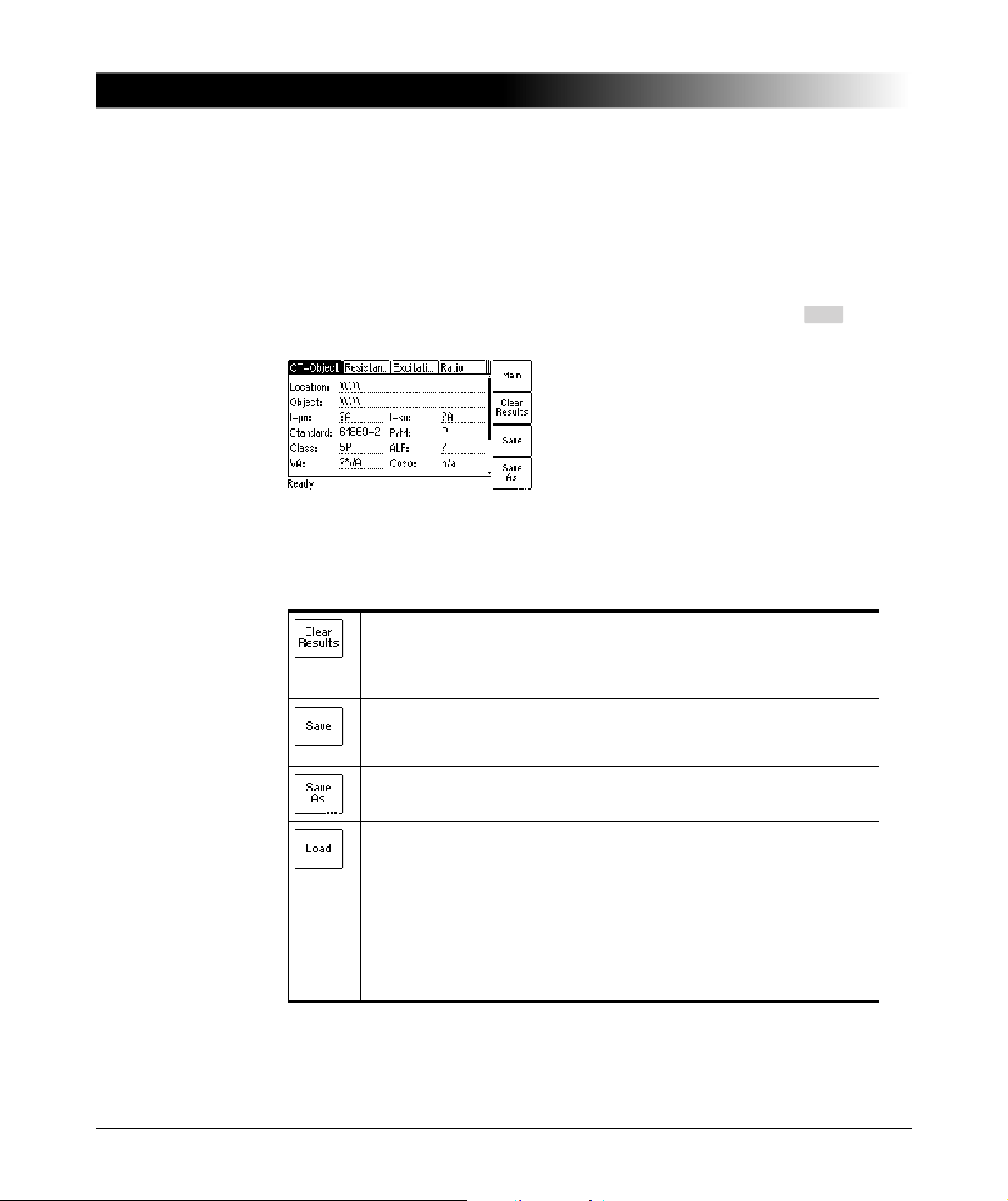
CT Analyzer User Manual
ESC
6.2 CT-Object Card
The CT-Object card is the most important card and always required for all types
of tests. In this card all necessary settings for a test are done. Some of the
settings contained in the CT-Object card are also shown in other cards for
information.
Note: The CT-Object card is the top user interface level. Pressing the key
several times will always bring you back to the CT-Object card.
Figure 6-1 CT-Object card with default settings after initializing a new CT
test
6.2.1 Available Soft Keys
Clears the results of the previous test and enables to start a new
test. All measurement results as well as all the parameters
previously determined using the "guesser function" are cleared. Text
entries for "Location" and "Object" remain unchanged.
Saves the test results and test settings to the currently loaded
CT Analyzer report file. If the test results have not been saved yet,
the Save As dialog is opened. Saving a file is described on page 64.
Saves the test results and test settings to a new .xml file. Saving a
file is described on page 64.
Allows to load a test stored on the Compact Flash card in order to
check its results, to recalculate the results with different settings or to
use its settings for a new test.
Note: Recalculation of the existing CT test results in order to verify
the behavior of the CT at different burdens or primary currents can be
performed by changing the burden value on the CT-Object card or
the primary current on the Ratio card. The recalculated results can
then be stored again like for a regular test.
80
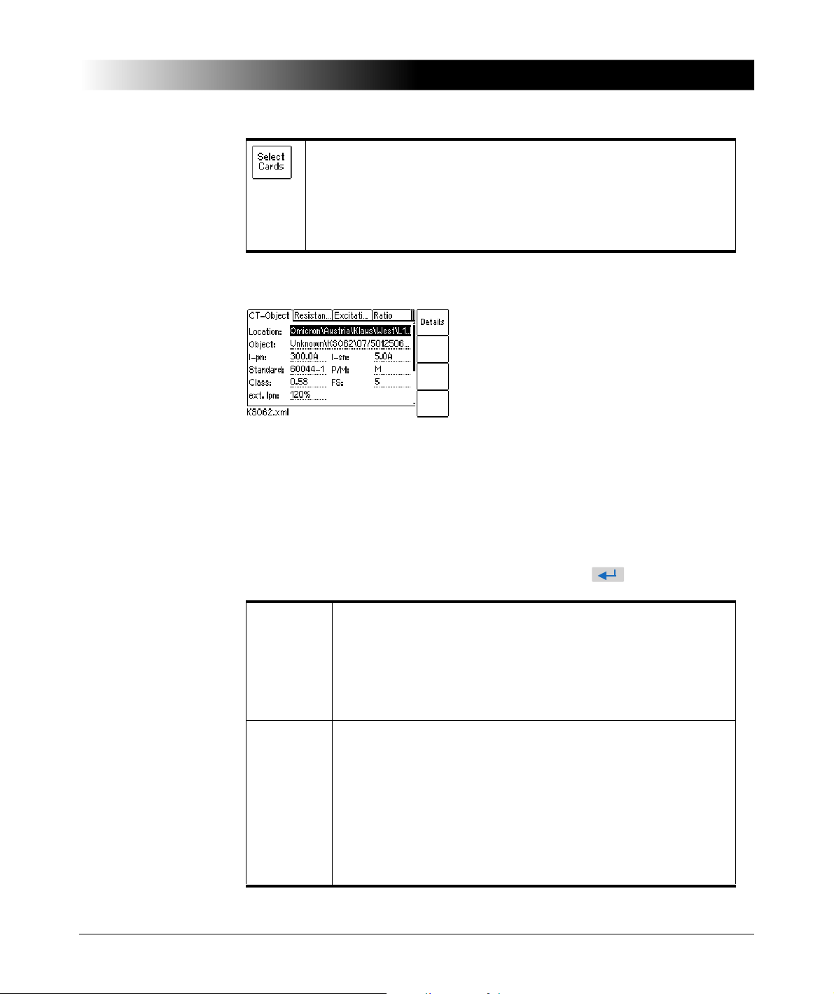
The CT Analyzer Test Cards
Opens the Select Cards page where you can select the test cards
for the current test. The Select Cards page is described on page 69.
Note: When loading a new CT test from the main menu (using the
"New CT-Test" entry), the test card selection defined in the default
test settings is used for this new test. The card selection performed
in the CT-Object card will then be discarded.
6.2.2 Information Fields to be Filled by the User
Figure 6-2 Editing the location settings in the CT-Object card
The "Location" and "Object" text fields are only used for reporting and
documentation purposes. They can be filled by the user after the test is finished.
These fields provide information about the location of the CT and the CT itself.
The content of these fields is defined in the Location settings page and the
Object settings page, respectively.
To open these settings pages, position the cursor on the "Location" or the
"Object" field and then press the Details soft key or the key.
Location
settings
page
Object
settings
page
The Location settings page provides the following text fields.
Each field can contain a maximum of 40 numbers or letters.
• Company, Country, Station, Feeder:
Information where the CT is installed.
• Phase: Phase to which the CT is connected.
• IEC-ID: IEC-ID of the CT or freely definable information.
The Object settings page provides the following text fields.
Each field can contain a maximum of 40 numbers or letters.
• Manufact.: Manufacturer of the CT under test.
• Type: Type number or description of the CT under test.
• Serial No.: Serial number of the CT under test.
• Core: Number of the tested core.
• Tap: Description of the tap (e.g. 1S1-1S3, X1-X4, ...).
• Optional 1: Optional field for free use.
81

CT Analyzer User Manual
6.2.3 Parameters and Settings Used or Determined by the Test Process
The fields described in this section are used and/or determined by the test
process.
Figure 6-3 Editing the CT-Object card
Note: If the "Check "*" settings before start" option is enabled in the default test
settings (see section 5.7.3 ”Miscellaneous Settings” on page 70), no automatic
assessment will be available if you do not enter data for a parameter that is
relevant for assessment. Such parameters are marked by a star "*" in the
CT Analyzer user interface and in the following tables.
82

The CT Analyzer Test Cards
Common Parameters and settings displayed for all standards,
CT types and classes
The table below lists all parameters and settings that are displayed for all
standards, CT types and classes.
In addition to these common parameters, specific additional parameters are
displayed in the CT-Object card depending on the selected standard, CT type
(protection or metering CT) and class. For these specific parameters, please
refer to the tables on pages 87 to 99.
Parameter Description
I-pn Rated primary current.
Possible values: 1 to 99000A or ?
I-sn Rated secondary current.
Possible values: 0.0001 to 25A or soft keys 1.0, 2.0, 5.0, 1.0A/ √3, 2.0A / √3,
5.0A/ √3 or ?
Default: ?.
Standard Standard according to which the test has to be performed.
Possible values: Soft keys IEC 60044-1, IEC 60044-6, IEEE C57.13 or
IEC 61869-2
Default: Standard defined in the default test settings.
Note: Using the IEEE C57.13 standard for transformers with gapped cores
may possibly deliver incorrect results.
P/M * Definition of CT type: Protection or metering CT.
Possible values: Soft keys Prot. CT, Meter. CT or ?
Default: As defined in the default test settings.
* This parameter is relevant for assessment. No automatic assessment is
available if the user did not enter data for this parameter prior to the test (see
page 82).
1
.
1
soft key. Default: ?.
1
.
83

CT Analyzer User Manual
Parameter Description
Class * Accuracy class of the CT.
Possible values: Depending on the selected standard or ?
Default: As defined in the default test settings.
This parameter is only displayed, after the parameters "Standard" and "P/M"
have been defined or determined by the CT Analyzer. Depending on these
parameters, the parameters for the CT class can be selected using the soft
keys.
Note: The class can be selected by soft keys or is determined by the
CT Analyzer during the test. Automatic determination during the test only
works for IEC 61869-2 or IEC 60044-1 metering CTs and IEEE C57.13
metering CTs. If the question mark has been entered for the "P/M" parameter,
the "Class" cannot be defined by the user but is automatically determined by
the CT Analyzer instead.
* This parameter is relevant for assessment. No automatic assessment is
available if the user did not enter data for this parameter prior to the test (see
page 82).
For IEEE C57.13 metering CTs only:
An additional soft key Assess @ VA is available for metering CTs according
to IEEE C57.13. Use this option if the accuracy class of the CT only applies
to one specific burden.
CT assessment is normally performed for the maximum burden specified
("VA" or "Burden" parameter) and all lower burdens defined in the standard.
Example: If the burden specified is B-0.9, the assessment is performed for
the burdens B-0.9, B-0.5, B-0.2 and B-0.1 (and the electronic burdens E-0.2
and E-0.04).
Selecting the Assess @ VA option in addition to the class setting will cause
the CT Analyzer to consider only the burden value specified prior to testing
for the CT assessment. The ratio table and the phase table in the Ratio card
then only show the error for this specific burden (see section 6.7.5 on page
123).
When Assess @ VA is selected, the soft key changes to Assess all VA to
enable deactivation of this option.
1
.
84

Parameter Description
α
5
I
rated
-------------
2
=
VA *
Cos
ϕ
Burden
Cos
ϕ
f Rated frequency of the CT.
Nominal burden of the CT, used to calculate the behavior of the CT at the
nominal burden.
Possible values: 0 to 300VA or soft keys 1.0VA to 30VA or ?
Depending on the burden and the selected test standard, the corresponding
cos ϕ is used (cos ϕ not editable by the user).
* This parameter is relevant for assessment. No automatic assessment is
available if the user did not enter data for this parameter prior to the test (see
page 82).
If the IEEE C57.13 standard is selected with the type "metering CT"
CT Analyzer offers some soft keys (e.g. B-0.1, B-0.2, B-0.5 etc.) with
standard loads for the power. If these soft keys are used, the power is
calculated according to table 9 of IEEE C57.13. If the rated current is not 5A,
the resistance and inductance of the table is multiplied by the factor
If the IEEE C57.13 standard is selected with the type "protection CT" (class
C, K or T), the VA and Cos ϕ parameters are not accessible to the user. In
this case, the user has to enter the terminal voltage V
parameters and settings displayed for IEEE C57.13 protection CTs" on
page 98.
"Burden" and "Cos ϕ" are used to define the operating burden connected to
the CT. These parameters are used to calculate the behavior of the CT at
the operating burden (connected burden) and the corresponding cos
Possible values for "Burden": 0 to 300VA or soft keys 1.0VA to 30VA or ?
Possible values for "Cos
These parameters can also be changed after the test or in a loaded test
report in order to check the CT behavior at different burden values.
Special behavior depending on available test cards:
If the test contains a Burden card, a question mark is automatically entered
to the fields "Burden" and "cos ϕ" and entering the burden is not possible
until the test is finished. In this case, the value determined during the burden
test is automatically entered after burden measurement. If I
burden is updated immediately after the burden test is finished. If I
defined (entry "?"), the burden is updated after the resistance test.
Possible values: Integer value between 16 and 400 Hz or soft keys 16.7Hz,
50Hz, 60 Hz or 400 Hz.
Default: Frequency defined in the default test settings.
ϕ": 0 to 1.
The CT Analyzer Test Cards
1
.
, the
instead. See "Specific
b
ϕ.
1
.
is defined, the
sn
is not
sn
85

CT Analyzer User Manual
Parameter Description
Rprim Specified primary winding resistance (only available if primary winding
Class mult.
factor
Delta compensation
resistance measurement is enabled for the test).
Possible values: 0 to 3000 ohms or soft key ?
Default: ?.
Class multiplying factor.
This factor increases the assessment level for the ratio test. E.g. a class
multiplier of 0.5 means that the maximum accepted tolerance for the ratio
error is only half the standard tolerance.
Possible values: 0.25 to 1.00 or soft key 1.0.
Default: 1.0 (as set in the device settings: Main Menu, entry "Settings" ->
Setting Menu, entry "Misc. Settings").
Correction factor for the ratio measurement. This factor enables the ratio
measurement for CTs that are installed inside a delta winding transformer.
Possible values: Soft keys Ratio 1, Ratio 2/3 or Ratio 1/3.
Default: Ratio 1.
Choose "Ratio 1" if no correction is required.
Choose "Ratio 2/3" if input PRIM is connected to the two terminals of that
transformer winding, the CT is in series with.
Choose "Ratio 1/3" if input PRIM is connected to the terminals of a
transformer winding, the CT is not in series with.
1
.
1. If the question mark is entered for this parameter and a new test is started, the CT Analyzer
automatically tries to determine the value using its integrated guesser function (see chapter 7 on
page 131).
86

The CT Analyzer Test Cards
Specific parameters and settings displayed for IEC 60044-1
protection CTs
The following parameters are only displayed in the CT-Object card if the
standard IEC 60044-1 is selected with the type "Protection CT".
Param. Description Available for IEC 60044-1
protection CTs, class
2P, 3P,
4P, 5P,
6P, 10P
ALF Accuracy limiting factor acc. to IEC 60044-1.
Possible values: Integer value from 1 to 300 or soft keys
1
?
, 5, 10, 15, 20 or 30.
Default: ?.
Rct Specified secondary winding resistance.
1
Possible values: 0 to 3000 ohms or soft key ?
.
Default: ?
Ts Specified secondary time constant.
Possible values: 0.000 to 100.0s or soft key ?
1
.
Default: 100s.
Kx Dimensioning factor acc. to IEC 60044-1, PX.
Possible values: 1 to 300 or soft key ?
1
.
Default: ?.
Ek Rated knee point e.m.f.
Possible values: 0 to 20000 or soft key ?
1
.
Default: ?.
Ie Accuracy limiting current acc. to IEC 60044-1, PX.
Possible values: 0.03mA to 30 A or soft key ?
1
.
Default: ?.
E1 User-defined e.m.f. to verify the excitation current at this
specific e.m.f.
Possible values: 0.1 to 20000V or soft key ?
2
.
Default: ?.
Ie1 Maximum allowed excitation current at E
Possible values: 0.03mA to 30000 mA or soft key ?
.
1
3
.
Default: ?.
1. If the question mark is entered for this parameter and a new test is started, the CT Analyzer
automatically tries to determine the value using its integrated guesser function (see chapter 7 on
page 131).
2. If the question mark is entered, half the voltage entered or measured for Ek is used.
3. If the question mark is entered, the CT Analyzer uses the excitation current measured at the
voltage value defined at E
. In this case, the assessment for this parameter is OK.
1
2PR, 3PR,
4PR, 5PR,
6PR, 10PR
PX
xx
xx
x
x
x
x
x
x
87

CT Analyzer User Manual
Specific parameters and settings displayed for IEC 60044-1
metering CTs
The following parameters are only displayed in the CT-Object card if the
standard IEC 60044-1 is selected with the type "Metering CT".
Param. Description Available for
FS Instrument security factor acc. to IEC 60044-1.
ext. Ipn Extended current rating.
1. If the question mark is entered for this parameter and a new test is started, the CT Analyzer
IEC 60044-1
metering CTs,
class
0.1, 0.2, 0.2s, 0.5,
0.5s, 1, 3, 5
Possible values: Integer value from 1 to 30 or soft keys ?
FS1.5, FS2, FS5, FS10, FS20 or FS30.
Default: ?.
Possible values: 100 to 400% or soft keys 120%, 150%, 200%,
300%, 400%.
Default: 120 %.
automatically tries to determine the value using its integrated guesser function (see chapter 7 on
page 131).
1
, FS1,
x
x
88

The CT Analyzer Test Cards
T
p
K1–
ω
------------ -=
Specific parameters and settings displayed for IEC 60044-6
The following parameters are only displayed in the CT-Object card if the
standard IEC 60044-6 is selected.
Param. Description Available for
IEC 60044-6, class
TPS TPX TPY TPZ
Rct Specified secondary winding resistance.
Possible values: 0 to 3000 ohms or soft key ?
Default: ?
Kssc Rated symmetrical short-circuit current factor.
Possible values: 1 to 300 or soft keys ?
1
, 3, 5, 7.5, 10,
12.5, 15, 17.5, 20, 25, 30, 40 or 50.
Default: ?.
Tp Primary time constant.
Possible values: 0.000 to 5.000s or soft keys 20ms,
40ms, 60ms, 80ms, 100ms or 120ms.
T
depends on K as follows:
p
1
.
xxxx
xxxx
xxxx
K Dimensioning factor.
Possible values: 1 to 1572.
K depends on T
as described above for Tp.
p
V-al Rated equivalent excitation limiting secondary voltage.
1
Possible values: 0 to 9999V or soft key ?
.
Default: ?.
I-al Accuracy limiting secondary excitation current.
Possible values: 0.03mA to 30 A or soft key ?
1
.
Default: ?.
E1 User-defined e.m.f. to verify the excitation current at this
specific e.m.f.
Possible values: 0.1 to 20000V or soft key ?
Ie1 Maximum allowed excitation current at E
2
.
(user-defined
1
e.m.f.).
Possible values: 0.03mA to 30 A or soft key ?
3
.
Ktd Rated transient dimensioning factor.
Possible values: 1.0 to 2043 or soft key ?
1
.
Default: ?.
x
x
x
x
x
xxx
89

CT Analyzer User Manual
Param. Description Available for
Ts Specified secondary time constant.
Duty Specified duty cycle.
t1 Duration of first current flow. The specified accuracy limit
t-al1 Permissible time to accuracy limit for first energizing
t2 Duration of second current flow. The specified accuracy
t-al2 Permissible time to accuracy limit for second energizing
tfr Dead time between first opening and reclosure.
Possible values: 0.000 to 100.0s or soft key ?
1
.
Default: ?.
Using the soft keys, two different energizing cycles can
be selected: C-O or C-O-C-O
Default: C-O.
must not be reached within time t
al1
.
Possible values: 0.000 to 5.000s or soft key 100ms.
Default: 0.1s.
period of the duty cycle.
Possible values: 0.000 to 5.000s and max. t
or soft key
1
40ms.
Default: 0.04s.
limit must not be reached within time t
al2
.
Note: Only displayed if "Duty" is C-O-C-O.
Possible values: 0.000 to 5.000s or soft key 100ms.
Default: 0.1s.
period of the duty cycle.
Note: Only displayed if "Duty" is C-O-C-O.
Possible values: 0.000 to 5.000s and max. t
or soft key
2
40ms.
Default: 0.04s.
Note: Only displayed if "Duty" is C-O-C-O.
Possible values: 0.00 to 5.00s or soft key 300ms.
Default: 0.3s.
IEC 60044-6, class
TPS TPX TPY TPZ
xx
xx
xx
xx
xx
xx
xx
90

The CT Analyzer Test Cards
Param. Description Available for
IEC 60044-6, class
TPS TPX TPY TPZ
Ktd calculation
1. If the question mark is entered for this parameter and a new test is started, the CT Analyzer
2. If the question mark is entered, half the voltage entered or measured for E
3. If the question mark is entered, the CT Analyzer uses the excitation current measured at the
Calculation method for transient dimensioning factor Ktd.
Select a calculation method using the soft keys:
acc. to IEC 60044-1 (calculation exactly acc. to
standard), acc. to OMICRON (calculation considers CT
remanence) or acc. to GB 16847 (acc. to Chinese
xx
standard GB 16847).
Default: As defined in the default test settings (see
"Default Standard" parameter in section 5.7.1 on
page 65).
automatically tries to determine the value using its integrated guesser function (see chapter 7 on
page 131).
voltage value defined at E
. In this case, the assessment for this parameter is OK.
1
is used.
k
91

CT Analyzer User Manual
Specific parameters and settings displayed for IEC 61869-2
protection CTs
The following parameters are only displayed in the CT-Object card if the
standard IEC 61869-2 is selected with the type "Protection CT".
Param. Description Available for IEC 61869-2
ALF Accuracy limiting factor acc. to IEC 61869-2.
Rct Specified secondary winding resistance.
Ts Specified secondary time constant.
Kx Dimensioning factor acc. to IEC 61869-2.
Ek Rated knee point e.m.f.
E1 User-defined e.m.f. to verify the excitation
Ie Accuracy limiting current acc. to IEC 61869-2.
Ie1 Maximum allowed excitation current at E
Possible values: Integer value from 1 to 300
or soft keys ?
1
, 5, 10, 15, 20 or 30.
Default: ?.
Possible values: 0 to 3000 ohms or soft key
1
?
.
Default: ?
Possible values: 0.000 to 100.0s or soft key
1
?
.
Default: 100 s.
Possible values: 1 to 300 or soft key ?
1
.
Default: ?.
Possible values: 0 to 20000 or soft key ?
1
.
Default: ?.
current at this specific e.m.f.
Possible values: 0.1 to 20000V or soft key ?
Default: ?.
Possible values: 0.03mA to 30 A or soft key
1
?
.
Default: ?.
.
1
Possible values: 0.03mA to 30000 mA or soft
3
key ?
.
Default: ?.
protection CTs, class
protection transient
xP xPR PX PXR TPX TPY TPZ
protection
xx
xxx x x x
xxxx
xx
xx
2
.
xx
xx
xx
92

The CT Analyzer Test Cards
Param. Description Available for IEC 61869-2
protection CTs, class
Kssc Rated symmetrical short-circuit current factor.
1
Possible values: 1 to 300 or soft keys ?
, 3, 5,
7.5, 10, 12.5, 15, 17.5, 20, 25, 30, 40 or 50.
Default: ?.
Spec. The accuracy class assessment has to be
performed for the specific protection
requirements the CT is built for. According to
the standard, these requirements are normally
stated by the duty cycle and the time
constants.
However, in some cases the choice of one
specific duty cycle/time constant cannot
describe all protection requirements.
Therefore, the CT Analyzer offers the
possibility to specify "more general
requirements" (which cover the requirements
of different duty cycles and time constants) by
entering the K
instead.
td
Use the soft keys to choose if you want to
specify the protection requirements used for
the accuracy class assessment
• by specifying the duty cycle and the
necessary time constants (by Duty,
standard specification according to
IEC 61869-2; the CT Analyzer then
calculates the K
automatically from the
td
entered values)
• or alternatively by specifying the rated
transient dimensioning factor K
stated on
td
the CT’s name plate (by Ktd, alternative
specification according to IEC 61869-2).
The setting of this parameter displays or hides
the parameters K
, and Tp, Duty and t
td
al1
(see
parameter descriptions below).
Possible values: Soft keys by Duty or by Ktd.
Default: As defined in the default test settings.
protection transient
xP xPR PX PXR TPX TPY TPZ
protection
xxx
xxx
93

CT Analyzer User Manual
T
p
K1–
ω
------------ -=
Param. Description Available for IEC 61869-2
Ktd * Rated transient dimensioning factor according
Tp * Primary time constant.
Duty Specified duty cycle.
to the name plate.
Note: Only displayed if parameter "Spec." is
"by Ktd".
Possible values: 1.0 to 2043 or soft key ?
1
.
Default: ? or ?*.
* If displayed, this parameter is relevant for
assessment. No automatic assessment is
available if the user did not enter data for this
parameter prior to the test (see page 82).
Note: Only displayed if parameter "Spec." is
"by Duty".
Possible values: 0.000 to 5.000s or soft keys
20ms, 40ms, 60ms, 80ms, 100ms or 120ms.
T
depends on K as follows:
p
Default: ? or ?*.
* If displayed, this parameter is relevant for
assessment. No automatic assessment is
available if the user did not enter data for this
parameter prior to the test (see page 82).
Note: Only displayed if parameter "Spec." is
"by Duty".
Using the soft keys, two different energizing
cycles can be selected: C-O or CO-CO
Default: C-O.
protection CTs, class
protection transient
protection
xP xPR PX PXR TPX TPY TPZ
xxx
xxx
xxx
94
The CT Analyzer Test Cards
Param. Description Available for IEC 61869-2
protection CTs, class
t-al1 * Permissible time to accuracy limit for first
energizing period of the duty cycle.
Note: Only displayed if parameter "Spec." is
"by Duty".
Possible values: 0.000 to 5.000s and max. t
or soft key 40ms.
Default: ? or ?*.
* If displayed, this parameter is relevant for
assessment. No automatic assessment is
available if the user did not enter data for this
parameter prior to the test (see page 82).
t1 * Duration of first current flow. The specified
accuracy limit must not be reached within time
t
.
al1
Note: Only displayed if parameter "Spec." is
"by Duty" and "Duty" is "CO-CO".
Possible values: 0.000 to 5.000s or soft key
100ms.
Default: ? or ?*.
* If displayed, this parameter is relevant for
assessment. No automatic assessment is
available if the user did not enter data for this
parameter prior to the test (see page 82).
tfr * Dead time between first opening and
reclosure.
Note: Only displayed if parameter "Spec." is
"by Duty" and "Duty" is "CO-CO".
Possible values: 0.00 to 5.00s or soft key
300ms.
Default: ? or ?*.
* If displayed, this parameter is relevant for
assessment. No automatic assessment is
available if the user did not enter data for this
parameter prior to the test (see page 82).
protection transient
xP xPR PX PXR TPX TPY TPZ
1
protection
xxx
xxx
xxx
95
CT Analyzer User Manual
Param. Description Available for IEC 61869-2
t-al2 * Permissible time to accuracy limit for second
1. If the question mark is entered for this parameter and a new test is started, the CT Analyzer
2. If the question mark is entered, half the voltage entered or measured for E
3. If the question mark is entered, the CT Analyzer uses the excitation current measured at the
protection CTs, class
protection transient
xP xPR PX PXR TPX TPY TPZ
protection
energizing period of the duty cycle.
Note: Only displayed if parameter "Spec." is
"by Duty" and "Duty" is "CO-CO".
Possible values: 0.000 to 5.000s or soft key
40ms.
xxx
Default: ? or ?*.
* If displayed, this parameter is relevant for
assessment. No automatic assessment is
available if the user did not enter data for this
parameter prior to the test (see page 82).
automatically tries to determine the value using its integrated guesser function (see chapter 7 on
page 131).
voltage value defined at E
. In this case, the assessment for this parameter is OK.
1
is used.
k
96

The CT Analyzer Test Cards
Specific parameters and settings displayed for IEC 61869-2
metering CTs
The following parameters are only displayed in the CT-Object card if the
standard IEC 61869-2 is selected with the type "Metering CT".
Param. Description Available for
IEC 61869-2
metering CTs,
class
0.1, 0.2, 0.2s, 0.5,
0.5s, 1, 3, 5
FS Instrument security factor acc. to IEC 61869-2.
Possible values: Integer value from 1 to 30 or soft keys ?
FS1.5, FS2, FS5, FS10, FS20 or FS30.
Default: ?.
ext. Ipn Extended current rating.
Possible values: 100 to 400% or soft keys 120%, 150%, 200%,
300%, 400%.
Default: 120%.
ext. VA Extended burden range for ratio error and phase displacement
assessment according to IEC 61869-2.
The assessment of the ratio error and the phase displacement is
usuallly performed down to a burden of 12.5% of the nominal
burden. If the "ext. VA" parameter is set to "on", the assessment
is performed for an extended range down to a burden of 1VA if
the limit of 12.5% results in a burden higher than 1VA.
Possible values: Soft keys On or Off.
Default: On.
1. If the question mark is entered for this parameter and a new test is started, the CT Analyzer
automatically tries to determine the value using its integrated guesser function (see chapter 7 on
page 131).
1
, FS1,
x
x
x
97

CT Analyzer User Manual
Specific parameters and settings displayed for IEEE C57.13
protection CTs
The following parameter is only displayed in the CT-Object card if the
IEEE C57.13 standard is selected with the type "Prot. CT".
Param. Description Available for
Vb * Rated secondary terminal voltage.
Vk
Vk1
Ik
Ik1
RE(20*Isn) Ratio error at 20 * I
Rct Specified secondary winding resistance.
If the IEEE C57.13 standard is selected with the type
"protection CT" (class C, K or T), the VA and Cos
parameters are not accessible to the user. In this case, the
user has to enter the terminal voltage V
Possible values: Integer values from 10 to 1200V or soft
2
keys ?
, 10V, 20V, 50V, 100V, 200V, 400V or 800V.
Default: ? or ?*.
* This parameter is relevant for assessment. No automatic
assessment is available if the user did not enter data for
this parameter prior to the test (see page 82).
User-defined measuring point.
User-defined measuring point 1.
Possible values: Integer values from 0.1V to 20.000V or
soft key ?
Default: ?.
User-defined measuring point.
User-defined measuring point 1.
Possible values: Integer values from 0.03mA to
30.000mA or soft key ?
Default: ?.
Possible values: Integer values from 1% to 99%.
Default: 10%.
Possible values: 0 to 3000 ohms or soft key ?
Default: ?
1
.
2
.
.
sn
instead.
b
ϕ
1
.
IEEE C57.13, class
C T X K
xx x
xx
xx
x
x
1
98
1. Acc. to IEEE C57.13 (1993)
2. If the question mark is entered for this parameter and a new test is started, the CT Analyzer
automatically tries to determine the value using its integrated guesser function (see chapter 7 on
page 131).
 Loading...