

Page 1
27
CMC 156
Reference Manual
Page 2

Test Set CMC 156
2
Article Number VESD1002 - Version CMC156.AE.9
© OMICRON electronics. All rights reserved.
This manual is a publication of OMICRON electronics GmbH.
All rights including translation reserved. Reproduction of any kind, e.g., photocopying, microfilming,
optical character recognition and/or storage in electronic data processing systems, requires the explicit
consent of OMICRON electronics. Reprinting, wholly or in part, is not permitted.
The product information, specifications, and technical data embodied in this manual represent the
technical status at the time of writing and are subject to change without prior notice.
We have done our best to ensure that the information given in this manual is useful, accurate and
entirely reliable. However, OMICRON electronics does not assume responsibility for any inaccuracies
which may be present.
The user is responsible for every application that makes use of an OMICRON product.
OMICRON electronics translates this manual from the source language English into a number of other
languages. Any translation of this manual is done for local requirements, and in the event of a dispute
between the English and a non-English version, the English version of this manual shall govern.
Page 3

Safety Instructions
3
Safety Instructions
ATTENTION: Before starting up the CMC 156, carefully read the following
safety instructions.
The system must not be put into operation without full knowledge of this
information!
The CMC 156 may only be operated by trained personnel on the
company premises!
Page 4

Test Set CMC 156
4
For your safety
The generator outputs supply voltages up to 125 V
rms
therefore:
• Operate the CMC 156 only with mains suppy with protective grounding!
• Connecting of one of the front-sided connectors to protective ground is not
permissible as this may cause dangerous contact voltages at all front panel
connectors. Grounding of a voltage output causes that also the sockets of
the analog inputs as well as the current outputs and N-connectors have
phase voltage.
• Use only measuring cables with 4 mm banana plugs and plastic jacketing
for connection to banana sockets; always insert plugs up to the stops.
Recommendation: use 4 mm safety banana plugs.
• Do not leave test leads exposed; always disconnect test leads at the
CMC 156 first!
• When connecting and disconnecting the test object make sure that all
generator outputs have been turned "OFF". Never disconnect the test
object when in a manual program section a switch in the software is "ON"
or a sweep is still under way (e.g. V, I, ϕ).
• All front panel sockets are to be considered as dangerous voltage contacts
with working voltages of up to 250V
rms
. Therefore only cables certified to
the corresponding national standards institute may be used.
• If the generator section lamp lights, there is a dangerous contact voltage
(> 42 Vpk) at least at one of the three voltage outputs!
• Never insert conductive parts (screwdriver, etc.) into the sockets!
• Do not operate in a wet or humid environment (condensation).
• Do not operate if an explosive environment.
• External devices may only be connected to the SELV interfaces of the
CMC 156 (host-interface, Gen. out 7-12, ext. Interface) if they comply to the
SELV requirements according to EN60950.
Do not open the CMC 156 or remove any of its housing components
Voltages of up to 400 V will occur inside the unit! If the unit is opened,
warranty claims will become void.
If the mains fuse must be replaced (rear panel of the test set)
First disconnect the mains plug of the CMC test set!
Unscrew the plastic tile and change the fuse (T6.3AH 250V).
Page 5

Table of Contents
5
Table of Contents
Safety Instructions ................................................................................................... 3
Table of Contents ..................................................................................................... 5
1 Introduction ....................................................................................................... 7
2 Start-Up .............................................................................................................. 9
2.1 System components ............................................................................................................ 9
2.2 System Start ......................................................................................................................... 9
3 Design and Operation ..................................................................................... 11
3.1 Modules ..............................................................................................................................12
3.1.1 Host Interface .......................................................................................................13
3.1.2 Processor ..............................................................................................................13
3.1.3 D/A Converter + Reconstruction Filter .................................................................13
3.1.4 Measuring Module ................................................................................................14
3.1.5 Internal Current and Voltage Amplifiers ...............................................................15
3.1.6 Power Supply ........................................................................................................16
3.2 Signal Generation ..............................................................................................................17
3.3 Accuracy ............................................................................................................................19
4 Connectors and Interfaces ............................................................................. 20
4.1 Connectors on the Front Panel ..........................................................................................20
4.1.1 Generator Combination Socket for VOLTAGE OUTPUT, CURRENT OUTPUT .22
4.1.2 Measurement Combination Socket for BINARY INPUT and ANALOG INPUT ...24
4.2 Connections on the Back Panel .........................................................................................27
4.2.1 Gen. out 7-12 ........................................................................................................27
4.2.2 ext. Interface .........................................................................................................29
5 Technical Data ................................................................................................. 31
5.1 Mains Supply .....................................................................................................................31
5.2 Outputs ...............................................................................................................................32
5.2.1 Current Outputs CURRENT OUTPUT 1-3 ...........................................................33
5.2.2 Voltage Outputs VOLTAGE OUTPUT 1-3 ............................................................35
5.2.3 Interface for an External Amplifier ‘Gen. out 7-12’ ...............................................36
5.2.4 Binary Outputs Relays ..........................................................................................37
5.2.5 Binary Outputs Transistor .....................................................................................38
Page 6

Test Set CMC 156
6
5.3 Inputs ................................................................................................................................ 39
5.3.1 Binary Inputs ........................................................................................................ 39
5.3.2 Counter Inputs 100 kHz ....................................................................................... 41
5.3.3 Measuring Inputs ................................................................................................. 42
5.4 Computer Interface ........................................................................................................... 43
5.5 Ambient Conditions ........................................................................................................... 43
5.5.1 Climate ................................................................................................................. 43
5.5.2 Shock and Vibration ............................................................................................ 44
5.5.3 Electromagnetic Compatibility (EMC) .................................................................. 44
5.6 Safety ................................................................................................................................ 45
5.7 Mechanical Data ............................................................................................................... 45
6 Technical Data EP Option .............................................................................. 47
6.1 Outputs (EP option) .......................................................................................................... 48
6.1.1 Current Outputs CURRENT OUTPUT 1-3 .......................................................... 49
6.1.2 Voltage Outputs VOLTAGE OUTPUT 1-3 ........................................................... 53
6.1.3 Output Power with EP option ............................................................................... 55
7 Appendix ......................................................................................................... 57
7.1 Optional Devices ............................................................................................................... 57
7.1.1 Current Amplifier CMA 56 .................................................................................... 57
7.1.2 Current Amplifier CMA 156 .................................................................................. 58
7.1.3 Voltage and Current Amplifier CMS 156 ............................................................. 60
7.1.4 CMLIB B - Optional connection for meter testing ................................................ 62
7.2 Ordering Notes .................................................................................................................. 64
8 Contact Information / Technical Support ...................................................... 69
Index ....................................................................................................................... 71
Page 7

Introduction
7
1 Introduction
The CMC 156 test system consists of the components CMC 156 test set, a
computer and the CMC user software. External amplifiers and optional devices
can also be controlled optionally.
Due to its wide range of optional settings, the CMC 156 test set completely
eliminates the need for operating elements on the front panel - every function
is controlled by the software on the COMPUTER. This means the modulestructured application software as well as the configuration of the test system.
The CMC software is described in the CMC software user's manual.
This description exclusively refers to the hardware of the CMC 156 test set.
Page 8

Test Set CMC 156
8
Page 9
Start-Up
9
2 Start-Up
2.1 System components
Before start-up, please verify that all system components are present:
• CMC 156 test set
• Mains cable
• Connection cable CMC 156 ↔ computer (25-pole)
• Connection cable CMC 156 ↔ test object:
These are provided by the user.
• Standard computer with a parallel interface
2.2 System Start
The instructions below can be followed if the computer is set up completely
and the software is installed properly.
1
A description of the installation of the CMC software is found in your CMC
software manual, chapter 1 "Installation".
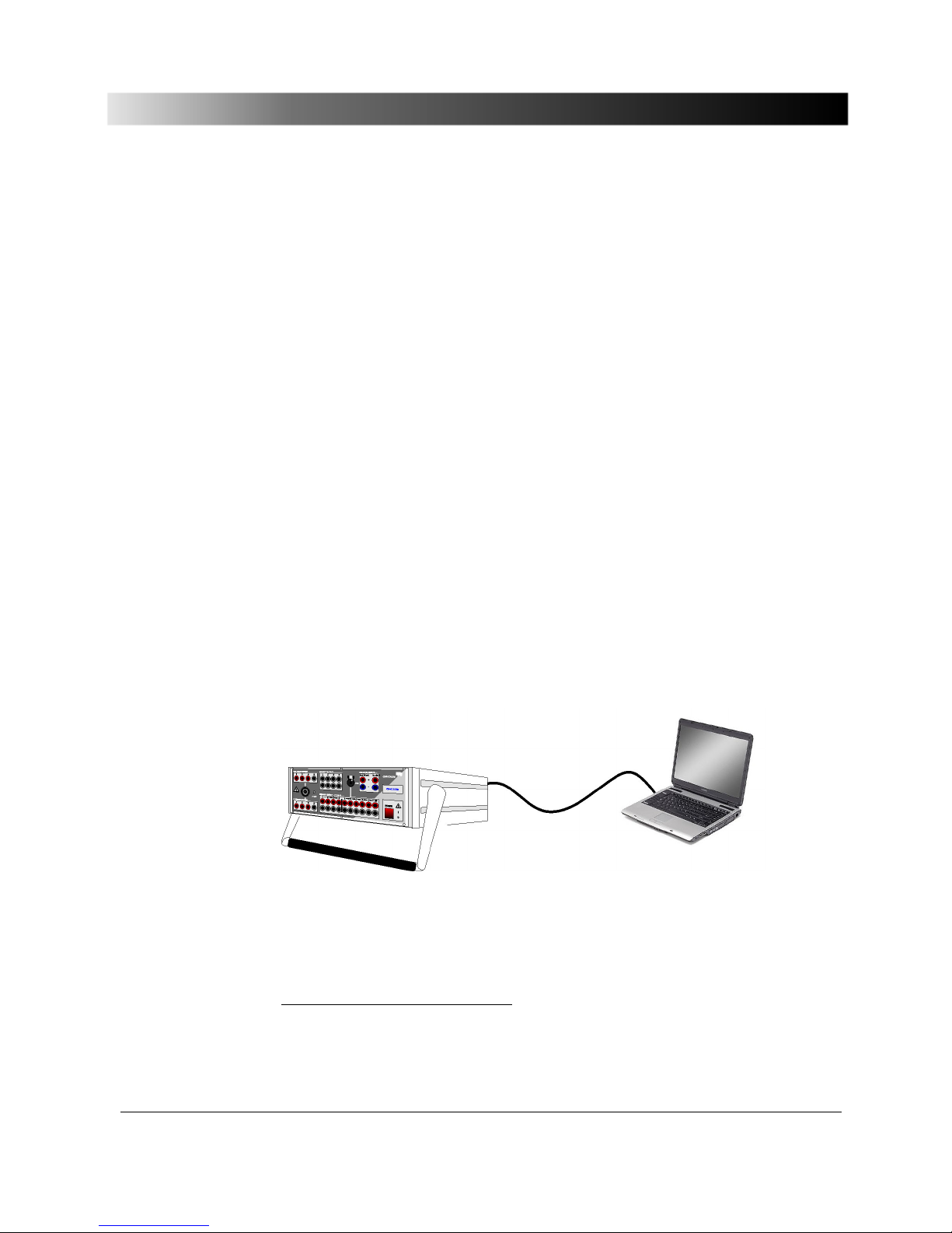
The following procedure is recommended to connect the system components:
Figure 1 Connection CMC 156 and computer
1
These instructions refer to a system including a computer and basic device CMC 156, i.e. without
additional amplifiers. If the system is to be operated with external amplifiers, please refer to the
instructions in your CMC SW user's manual, section "Configuring an external amplifier".
Page 10

Test Set CMC 156
10
Generally: Make sure that the ventilation slots at the rear panel of the
CMC 156 are free and clear!
1. Connect the CMC 156 test set to the computer:
• If the computer is equipped with a parallel printer port, use the 25-pole
cable (VEHK0002)
1
that was supplied with the test set to connect the
CMC 156 to the computer.
• If the computer is equipped with a USB port, use an OMICRON
CMUSB-P converter (ordering number VEHZ2007) instead of the
VEHK0002 to connect the CMC 156 to the computer.
2. Connect the CMC 156 and the computer to the power supply. (Power
supply cable is supplied.)
3. Power both units up. CMC 156: ON/OFF switch on the front panel.
4. For further actions, see the Installation in the appropiate software manual.
5. Start the software.
An extensive hardware test is carried out when the software is starting up. If
there is a hardware fault, the software will put out an appropriate message
after starting).
1
Only original centronics cable may be used due to the electromagnetic compatibility (EMC)
requirement for the connecting cable.
Page 11

Design and Operation
11
3 Design and Operation
Our computer-controlled design concept allows the following segregation of
functions:
Computer
• Application software
• Control and display
• Measuring data processing
• Reporting and archiving
CMC 156 test set
• Signal generation
• Voltage and current amplifier
• Input signal measurement
• Time-critical processes
Page 12
Test Set CMC 156
12
3.1 Modules
... Power GND potential
2
4
2
3
3
6
6
4
M
a
in
s
Low level
outputs
Gen. out 7 -12
Supply
Reinforced isolation
to mains
Isolation
for SELV
Isolation for
working voltage (relays)
Signal generator
and measuring units
Current amplifier
Voltage amplifier
±
1
0
V
I
n
p
u
t
± 20mA Input
B
in
a
r
y
o
u
t
p
u
t
s
1
-
4
B
in
a
r
y
in
p
u
t
s
5
-
1
0
Binary inputs
1-4
I
d
c
Udc
Counter inputs
ext. Interface
Binary outputs
(transistor)
ext. Interface
PC connection
Host Interface
P
C
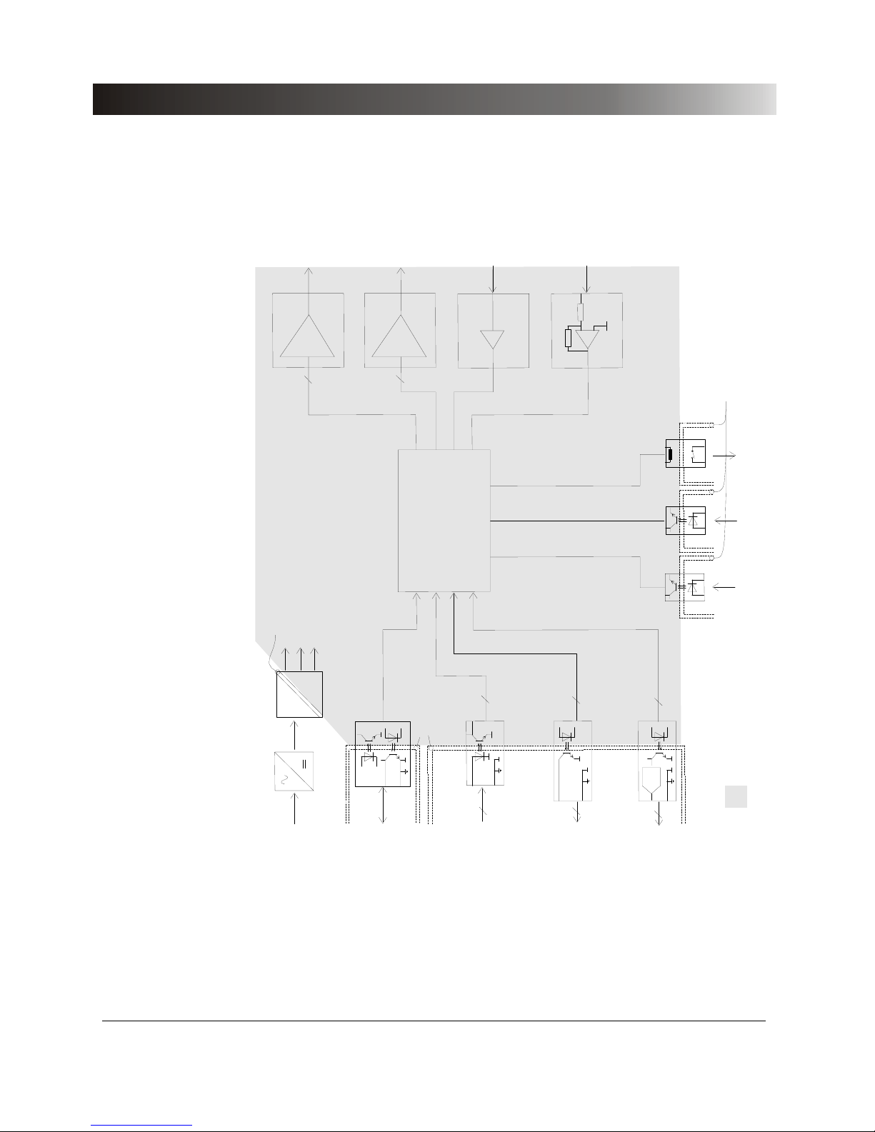
Figure 2 Basic block diagram of the CMC 156
Page 13

Design and Operation
13
3.1.1 Host Interface
The CMC 156 communicates with the computer via the Host Interface (parallel
printer interface) at its rear side.
If the computer is equipped with a parallel printer port, too, use the 25-pole
cable (VEHK0002) that was supplied with the test set to connect the CMC 156
to the computer.
If the computer is equipped with a USB port, use an OMICRON CMUSB-P
converter (ordering number VEHZ2007) instead of the VEHK0002 to connect
the CMC 156 to the computer.
3.1.2 Processor
A signal processor is the core of the test set hardware. It has the following
tasks:
• Communications with the host computer
• Signal generation
• Control of the test set hardware
• Input signal measurement and filtering
Its Harvard architecture and the built-in arithmetic unit make the signal
processor ideally suited for digital signal processing tasks.
For example, the signal processor needs for multiplication + adding + parallel
data transfer only two machine cycles (30ns). The CMC 156 uses this
advantage of the signal processor for signal generation and digital filtering.
3.1.3 D/A Converter + Reconstruction Filter
For D/A converters 16-bit PCM converters are used. Their high resolution
allows coverage of the entire amplitude range without range switching.
This is important in particular for fault simulation for protective devices,
because range switching in the test set via relays may cause erroneous
tripping when switching from a load to a fault condition.
The reconstruction low pass filter forms the desired output signal from the
stair-step output signals of the D/A converters and suppresses the high
frequency component, which is periodically repeated with the sampling
frequency. The 3dB bandwidth is at 3.1kHz.
Page 14

Test Set CMC 156
14
3.1.4 Measuring Module
The measuring module for analog signals primarily consists of a laser trimmed
high-precision voltage reference, a 16-bit A/D converter with series-connected
multiplexer and the appropriate input circuits (precision voltage divider, filter).
The input signals V
dc
and Idc, the output voltages, amplifier temperatures, etc.
are measured here. Behind the I
dc
input a PTC thermistor is located as
reversible fuse.
The binary inputs are read via opto-isolators having a time resolution of 100 μs
and are divided in two isolated groups (group 1: binary inputs 1..4; group 2:
binary inputs 5..10). The binary inputs can be configured by means of the
CMC software. You can specify if floating or potential-carrying contacts are to
be connected. For potential-carrying contacts, the expected rated voltage may
be specified (individually for each binary input) and the operating threshold of
the binary inputs may be set.
The operating threshold is set in % of the nominal voltage.
1
To isolate single binary inputs against each, other additional opto-Isolators
may be connected in series to the binary inputs.
For ordering notes see section 7.2, „Ordering Notes“.
The configuration of the binary inputs in the CMC software is described in your
CMC software user's manual, section "Configuring the binary inputs".
The binary inputs 1..10 can also be used as counter inputs for input
frequencies of up to 3kHz.
Additionally, for meter testing with higher frequencies
(e.g. with reference meters), two counter inputs for input frequencies of up to
100kHz are available at the ‘ext. Interf.’ interface.
1
Range: 10 to 71%; valid for binary inputs 1-10.
Page 15

Design and Operation
15
3.1.5 Internal Current and Voltage Amplifiers
The output amplifiers are designed as linear amplifiers and direct voltage
coupling with MOSFET output stages.
Using this technology, excellent harmonic distortion and frequency response
specifications can be realized in a very compact design.
The direct voltage coupling allows accurate representation of any transient
function.
Protection of the current and voltage outputs
If a current output is feed externally from one of the voltage outputs, it will not
self-destruct. However, if power is supplied from an external source, the
current output may be destroyed.
The voltage outputs are also protected against overload and sustained short
circuit by means of a fast electronic current limiter and temperature sensors.
Protection against transient overvoltage is effected by means of transient
absorbers.
If two voltage outputs are shorted against each other, the output elements are
brought close to their capacity limits, but they will not be destroyed.
For heat sink temperatures > 167°F (75°C), all outputs are thermally
disconnected (including the outputs on the rear panel of the test set).
Overload displays in the software
At the event of an overload at one of the current or voltage outputs a
corresponding display will be shown in the CMC software.
1
1
This display depends on the software version; for how your software will display these states,
please refer to chapter 3 of the CMC software manual.
Page 16

Test Set CMC 156
16
What to do in case of a switching OFF due to
overtemperature?
If a thermal switching OFF occurs due to a low ohmic burden in connection
with a high ON period, one of the following messages is displayed on screen:
Overtemperature at voltage output! All V and I outputs
switched off!
Overtemperature at current output! All V and I outputs
switched off!
The most important status messages can be found in chapter 13 of the CMC
software manual.
To avoid switching OFF, the power supply voltage of the current amplifier can
be reduced. For more information, please refer to the CMC software manual,
chapter ‘System configuration’.
3.1.6 Power Supply
The following power supplies are used in the CMC 156:
a. The mains-sided power supply with power factor correction creates an
intermediate circuit voltage for the supply of the connected isolated power
supplies.
b. Auxiliary supply for the supply of the processor and of all analog circuits of
the power amplifiers.
c. Supply for the voltage amplifiers
d. Supply for the current amplifiers
e. Supplies for the two isolated binary input groups
f. Supply for the parallel SELV1 interface to the computer
g. Supply for the analog SELV interfaces for controlling additional amplifiers
1
Safety extra-low voltage.
Page 17

Design and Operation
17
3.2 Signal Generation
To achieve the specified quality of the output signals, the generation of sine
signals of high quality is necessary. The requirement for 6 fixed-phase
coupled signals suggests a digital implementation.
In the CMC 156 the quality of the signals is achieved due to the use of a
modern and powerful signal processor.
The implemented algorithm linearly interpolates between the basic values of
any signal table according to the following equation:
S[i+x]=S[i]+x*{S[i+1]-S[i]}
S[i] .......... basic table value i
x ............. fractional component of the table pointer
The table may be processed with any real step width. The output of sine
signals uses the internal sine table which has 256 basic entries. The
frequency resolution is 2.33 μHz, and the phase resolution is < 50 μ degrees.
16k words are available per channel in the signal table for transient signals. By
means of interpolation, the signals are always output at 10k-samples/s, even if
the basic value table contains less samples/s, as is common in fault
recordings.
Page 18
Test Set CMC 156
18
Generator
triple
1
Generator
triple
2
Generator
triples
3 and 4
3
3
6
0 ... 5 V
rms
Gen. out 7-12
0 ... 125 V
rms
VO LTAGE
OUTPUT 1-3
0 ... 12,5 A
rms
CURRENT
OUTPUT 1-3
I
V
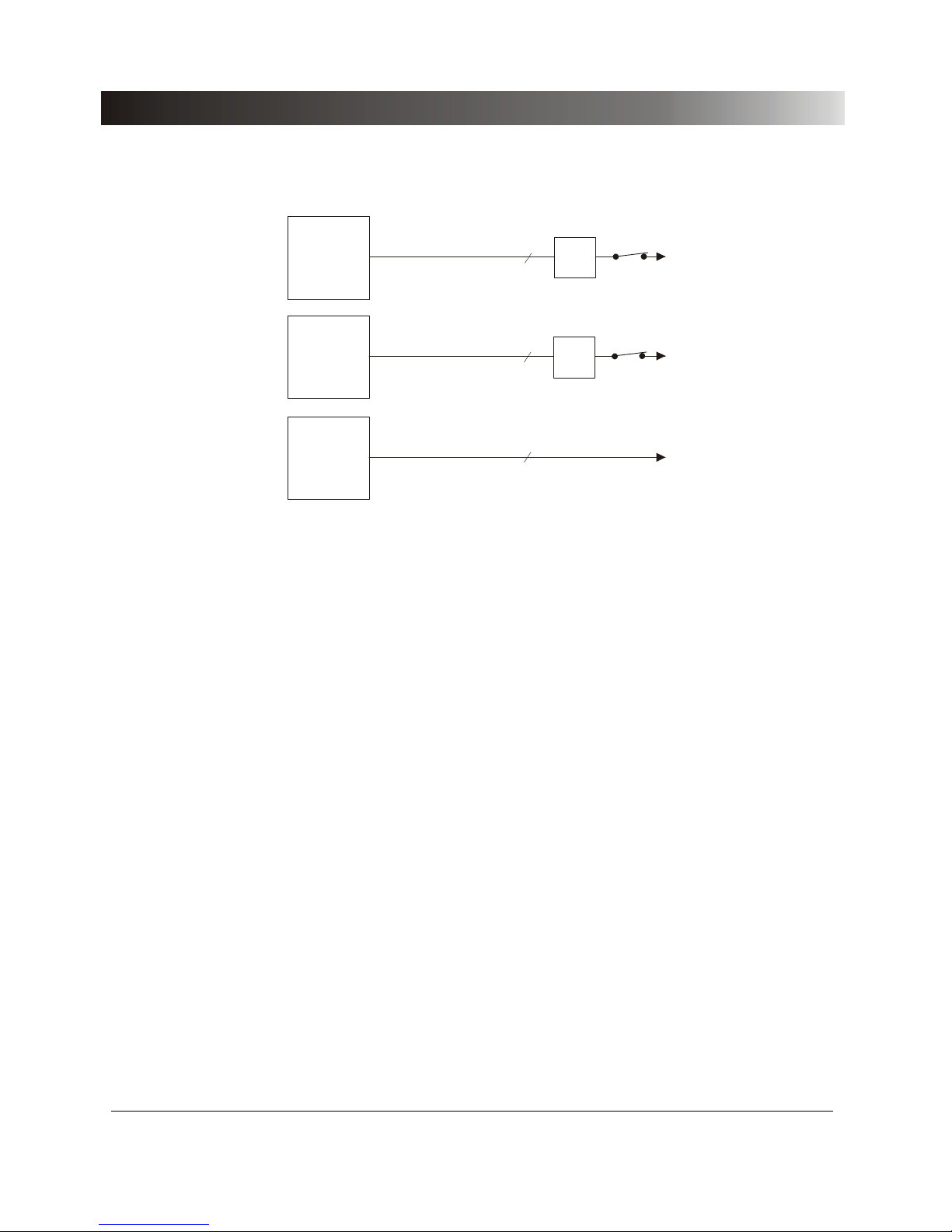
Figure 3 Block diagram of the generator outputs of the CMC 156
The CMC 156 test system supplies four generator triples
of three signals each.
The generator triples 1 and 2 are output via the internal amplifiers to the
outputs of the front panel.
• The generator triple 1 is output via the internal voltage amplifier to the
outputs VOLTAGE OUTPUT 1-3 on the front panel.
• The generator triple 2 is output via the internal current amplifier to the
outputs CURRENT OUTPUT 1-3 on the front panel.
The completely independent generator triples 3 and 4 are output on the
interface Gen. out 7-12 at the back panel, which is intended for controlling
external amplifiers (0 to 5V
rms
).
The generator triples 3 (Gen. out 7-9) and 4 (Gen. out 10-12) can be
• put out via external amplifiers, which can be connected via the isolated
interfaces at the back panel of the unit
or
• used directly.
The selection of the amplifiers takes place in the software.
The configuration of amplifiers in the CMC software is described in chapter 3
your CMC software user's manual.
Page 19
Design and Operation
19
3.3 Accuracy
The data sheet values for the CMC 156 are not typical values but guaranteed
values over one year from the time of factory calibration at 23 °C ± 5 %
(73 °F ± 10 °F).
Some factors had to be taken into account during development in order to
achieve the desired accuracy. For example, let's look at the signal path from
the signal generator to the output jack:
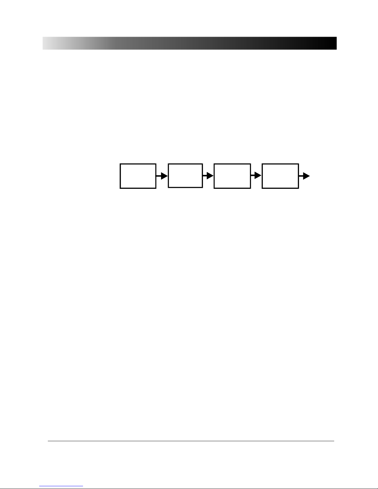
Si g n a l
generation
DSP
D/A co n ver t er Rec. f ilt er
A
mplifier
Output
signal
Figure 4 Output signal path
When the signal is generated in the DSP, an adequate bit width is ensured.
Naturally, the drift and the temperature coefficients are unimportant.
Therefore, the amplitude and offset correction is preferably carried out in the
DSP. There are no conventional trim pots (with poor temperature coefficients)
at all.
The amplification and offset errors of the D/A converters are corrected by the
DSP. For component selection the linearity as well as temperature and longterm drift were taken into account above all.
In the case of the voltage amplifier it is important that there is a gain-fixing
negative feedback across the entire amplifier, which is built via precision
resistors with corresponding temperature coefficient.
To ensure precision production appropriate measuring devices are necessary.
The measuring devices used by OMICRON are calibrated at regular intervals.
This ensures traceability to national and international standards.
Page 20
Test Set CMC 156
20
4 Connectors and Interfaces
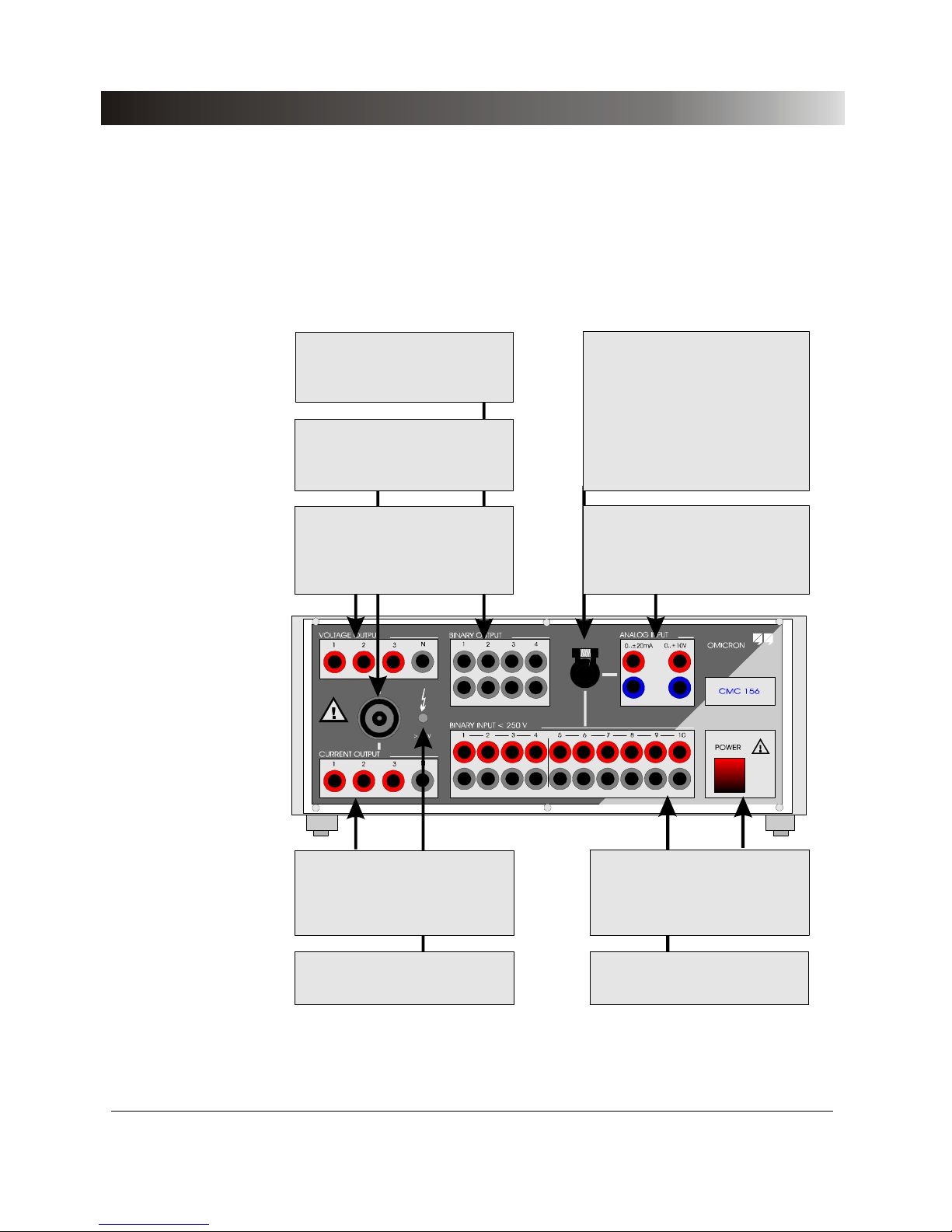
4.1 Connectors on the Front Panel
+
_
I
0
BINARY OUTPUT
4 internal floating binary outputs
routed out individually.
8-pole combinati on jack for outputs
and
.
(for assignment see the following)
VOLTAGE OUTPUT 1-3
CURRENT OUTPUT 1-3
VOLTAGE OUTPUT
VOLTAGE OUTPUT 1-3
Signals brought out via
internal amplifiers.
.
Combination jack for ,
20-pol e combination jack for the
following connections:
- current measuring input
- voltage measuring input
- 10 binary inputs
(for assignment see the following)
BINARY INPUT
ANALOG INPUT
ANALOG INPUT
0..±20mA: DC current input
routed out individually.
0..±10V: DC voltage input
routed out individually.
BINARY INPUT
Binary inputs 1 .. 10 routed out
individually.
POWER
Mains switch.
CURRENT OUTPUT
CURRENT OUTPUT 1-3
Signals brought out via
internal amplifiers.
.
Warn dis play
:
At least one phase has
more than 42 V.
Figure 5 Front panel
Page 21
Connectors and Interfaces
21
P
o
w
e
r
_
G
N
D
C
o
n
n
e
c
tio
n
p
o
s
s
i
b
ilitie
s
G
N
D
B
I5
-
1
0
*
)
G
N
D
B
I1
-
4
*
)
0
.
.
.
±
2
0
m
A
0
.
.
.
±
1
0
V
+
-
+
-
0
..
2
5
0
V
=
3
4
5
6
F
r
o
n
t
p
a
n
e
l
A
N
A
L
O
G
I
N
P
U
T
B
I
N
A
R
Y
IN
P
U
T
5
-
1
0
B
I
N
A
R
Y
IN
P
U
T
1
-
4
1
2
3
N
1
2
3
N
1
2
3
4
S
o
f
tw
a
r
e
c
o
n
t
r
o
lle
d
V
O
L
T
A
G
E
O
U
T
P
U
T
/
C
U
R
R
E
N
T
O
U
T
P
U
T
B
I
N
A
R
Y
O
U
T
P
U
T
V
O
L
T
A
G
E
C
U
R
R
E
N
T
*
)
B
I
1
-
4
a
n
d
B
I
5
-
1
0
is
o
la
t
e
d
f
r
o
m
e
a
c
h
o
t
h
e
r
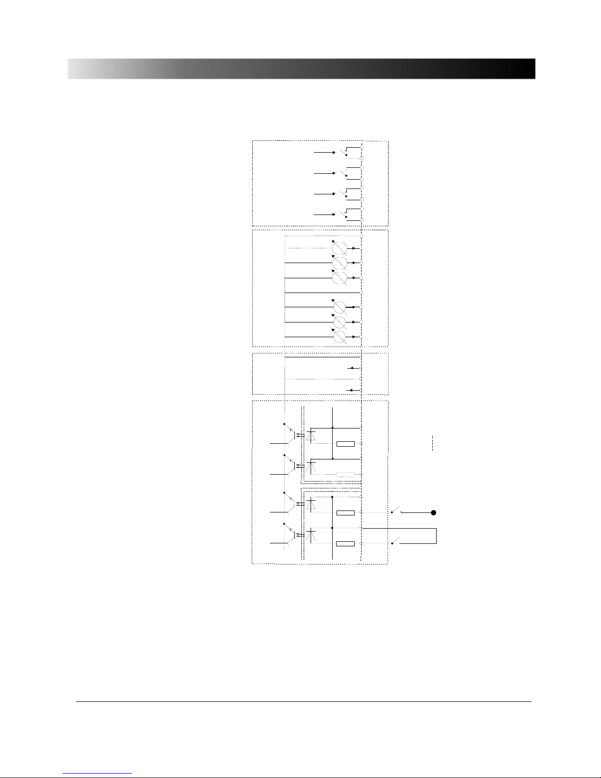
Figure 6 Outputs and inputs of the front panel
Page 22
Test Set CMC 156
22
4.1.1 Generator Combination Socket for
VOLTAGE OUTPUT, CURRENT OUTPUT
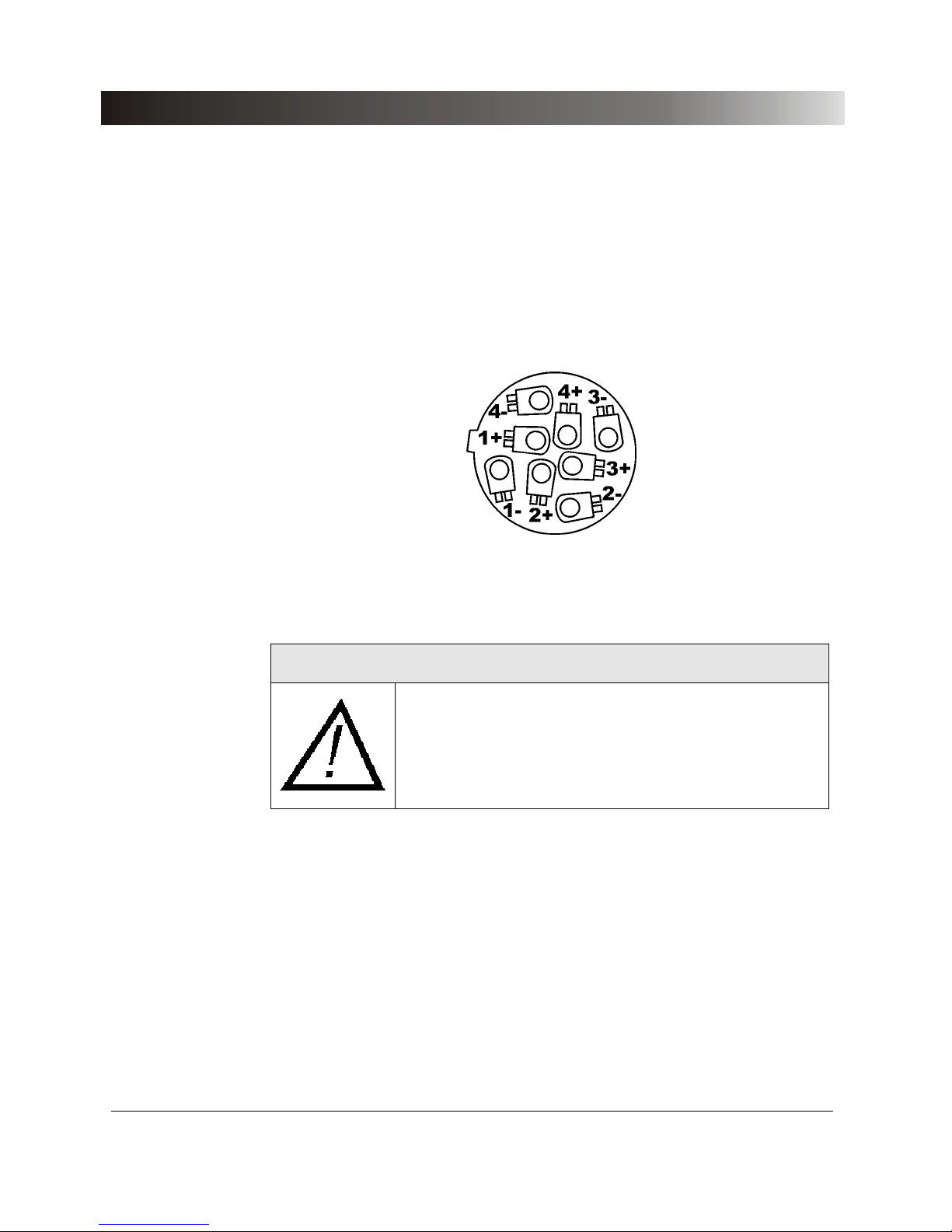
The combination socket CURRENT OUTPUT / VOLTAGE OUTPUT serves for
easy connection of the test object to the CMC 156. All signals of the
connection sections CURRENT OUTPUT and VOLTAGE OUTPUT are
brought out at this connector.
Figure 7 Plug for Generator Combination socket (view onto cable
connection side)
WARNING:
The connections on this socket are dangerous voltage
contacts when the test set is in its ON state; for this reason,
this socket may not be used without full knowledge of the
safety instructions found at the beginning of this manual.
Page 23
Connectors and Interfaces
23
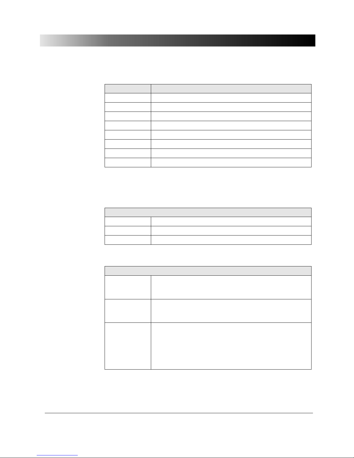
Pin Signal
1- Voltage_N
2- Voltage 3
3- Voltage 2
4- Voltage 1
1+ Current 1
2+ Current_N
3+ Current 3
4+ Current 2
Table 1 Assignment
Notice: For a left-hand rotating field Voltage_2 / Voltage_3 and
Current_2 / Current_3 are to be exchanged.
Manufacturer designation of plug for Generator Combination socket
Description SPEAKON LINE 8-pole
Article number NL8FC
Manufacturer Neutrik
Table 2 Manufacturer designation
Suppliers for plug for Generator Combination socket
USA Neutrik USA Inc., 195-S3 Lehigh Avenue, Lakewood,
NJ 08701-4527
Tel.: +1 (0)908 901 94 88, Fax: +1 (0)908 901 96 08
South Africa Eltron (Pty.) Ltd., P.O. Box 44598, Linden,
Johannesburg 2104,
Tel.: +27 (0)11 787 03 55, Fax: +27 (0)11 787 96 27
D Hermann Adam GMBH & CO KG
Felix -Wankel-Str. 1, 85221 Dachau,
Tel.: +49 (0)8131 2808-0 or
NCV GmbH,
Erzbischof Buchberger Allee 14, 93051 Regensburg,
Tel.: +49 (0)941 98041, FAX: +49 (0)941 999772
Table 3 Suppliers
If you want to order from OMICRON, refer to section 7.2 "Ordering Notes “.
Page 24
Test Set CMC 156
24
4.1.2 Measurement Combination Socket for
BINARY INPUT and ANALOG INPUT
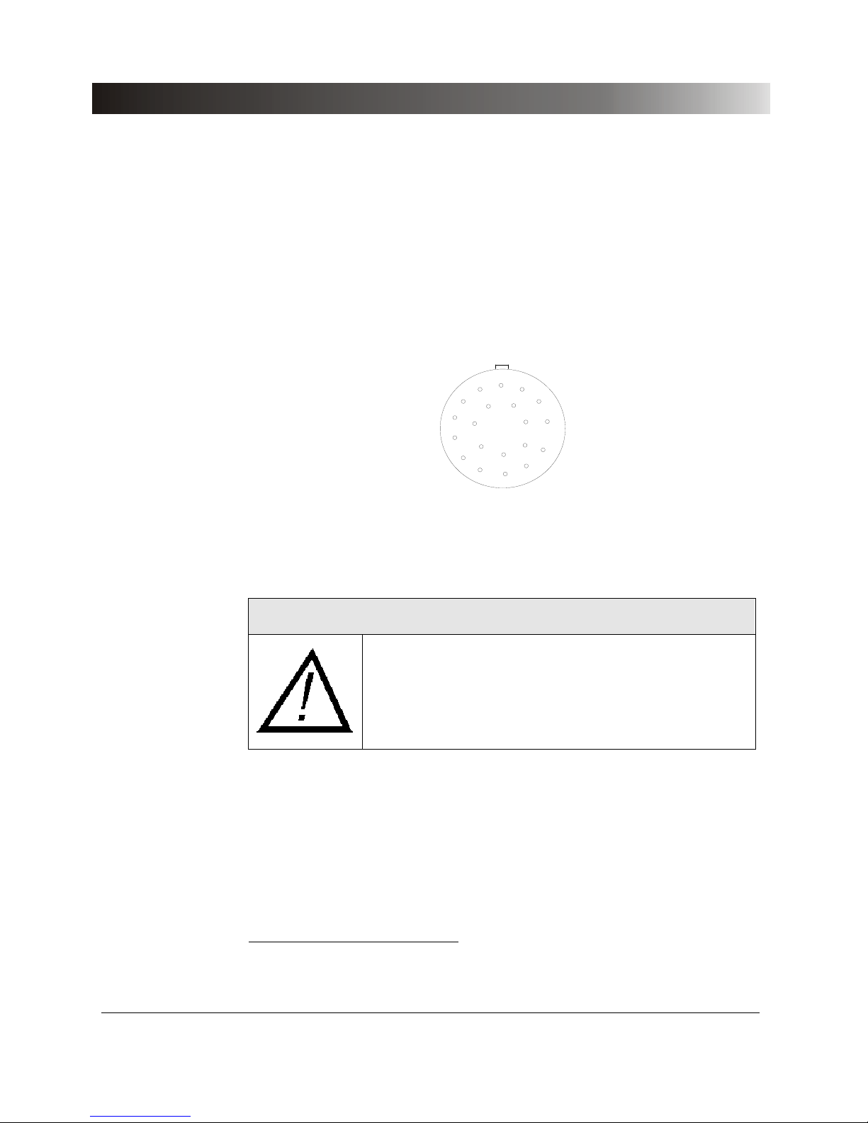
The combination socket BINARY INPUT / ANALOG INPUT serves for easy
connection of the test object to the CMC 156. All signals of the connection
sections BINARY INPUT and ANALOG INPUT are brought out at this
connector.
1
2
3
4
5
6
7
8
9
10
11
12
13
14
15
20
19
18
17
16
Figure 8 Plug for Measurement Combination socket (view onto cable
connection side)
1
WARNING:
The connections on this socket are dangerous voltage
contacts when the test set is in its ON state; for this
reason, this socket may not be used without full knowledge
of the safety instructions found at the beginning of this
manual.
1
Wires with max. 0.14mm² can be soldered on to this plug.
Page 25

Connectors and Interfaces
25
Pin Signal Cable color code Description
1 I7 wh Binary input 7
2 NC bn Not connected
3 NC gn Not connected
4 NC ye Not connected
5 I10 gy Binary input 10
6 I9 pk Binary input 9
7 I2 bu Binary input 2
8 I3 rd Binary input 3
9 GND_BI1 bk Binary GND 1
10 GND_BI2 vt Binary GND 2
11 I5 gy/pk Binary input 5
12 I6 rd/bu Binary input 6
13 I8 wh/gn Binary input 8
14 IDC*_IN bn/gn DC current input
15 NC wh/ye Not connected
16 NC ye/bn Not connected
17 I1 wh/gy Binary input 1
18 I4 gy/bn Binary input 4
19 GND_A wh/pk Analog GND
20 UDC_IN pk/bn DC voltage input
The shield is not connected within the CMC 156 and has therefore to be
connected within the signal source.
Table 4 Assignment Measurement Combination Socket
Page 26
Test Set CMC 156
26
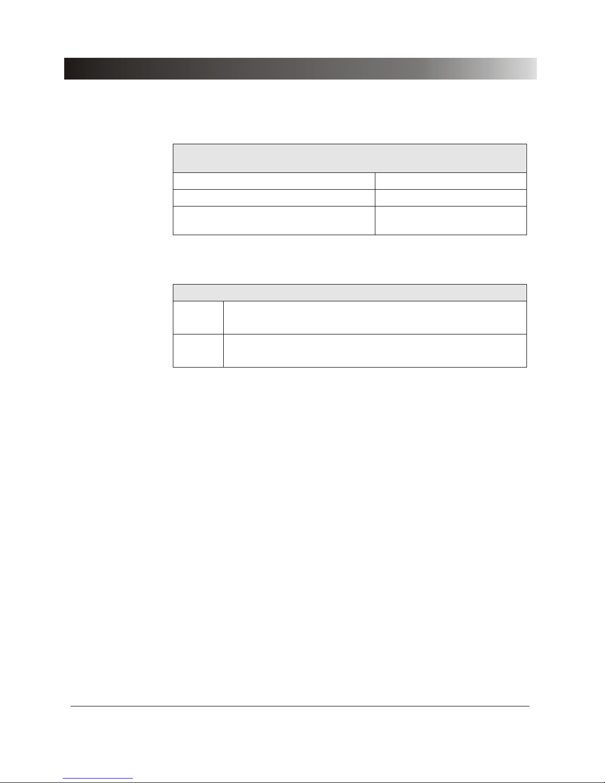
Manufacturer designation of plug for Measurement Combination
socket
Plug with guide cam and pull relief FGG.3B.320. PLAD9GY
Bend protection spout black GMA.3B.080.DG
Appliance socket with guide slot,
soldering contact
ENG.3B.320.PLLGY
Table 5 Manufacturer designation
Manufacturer / Supplier of plug for Measurement Combination socket
USA LEMO USA Inc. 335 Tesconi Circle, Santa Rosa, CA 95406,
Tel.: +1 (0)707 5788811, Fax: +1 (0)7075780869
D LEMOSA GmbH , Stahlgruberring 7, 81829 München 82
Tel. +49 (0)89 423085, Fax +49 (0)89 427192
Table 6 Manufacturer / Supplier
If you want to order from OMICRON, refer to section 7.2, "Ordering Notes “.
Page 27
Connectors and Interfaces
27
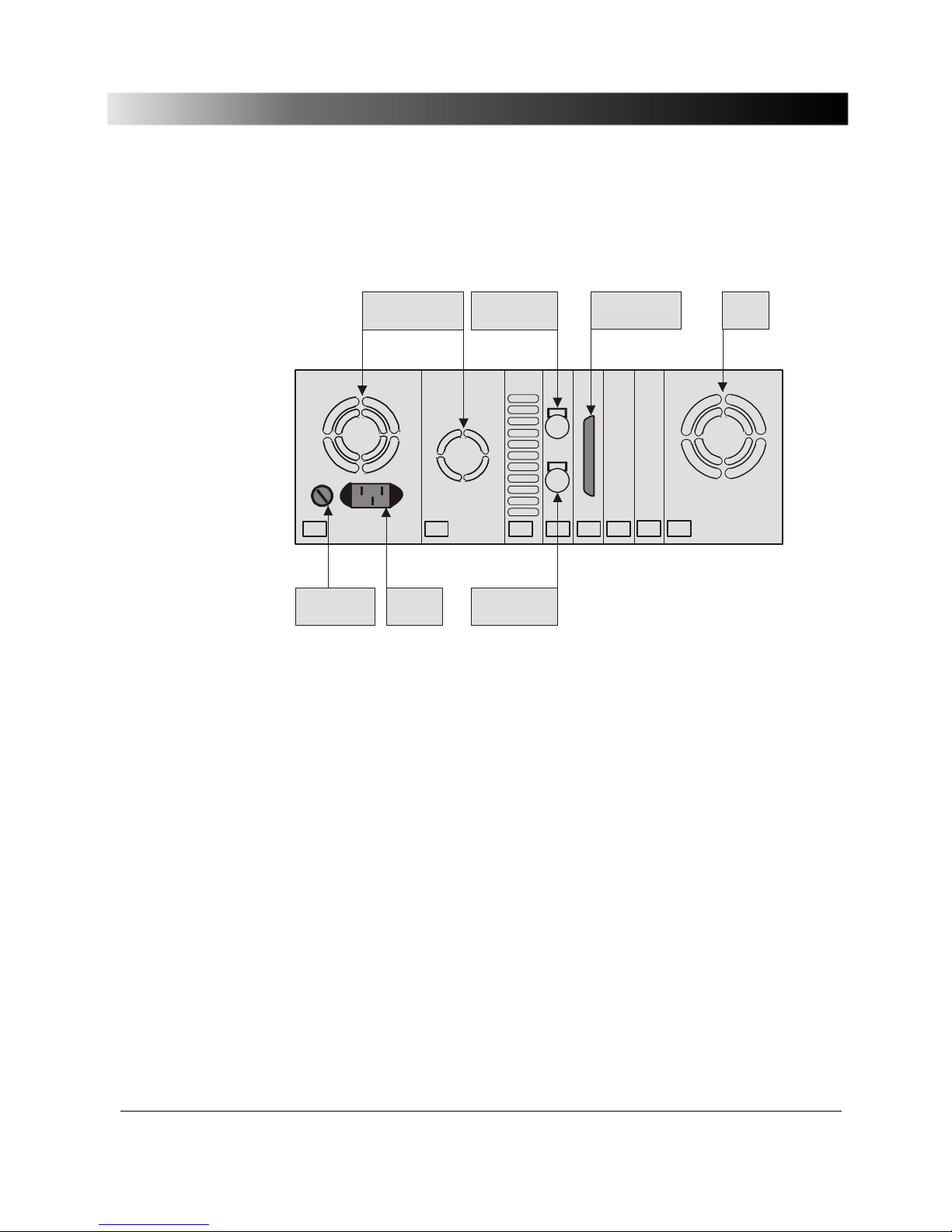
4.2 Connections on the Back Panel
Figure 9 Rear view CMC 156
4.2.1 Gen. out 7-12
At the socket Gen. out 7-12 two completely independent generator triples are
supplied. These signals can be used to control an external amplifier or to be
used directly as low level signal outputs.
For connection to this socket use the cable which is included in the scope of
delivery of the external amplifier (connection cable CMC 156 - amplifier).
The outputs are isolated from mains and the power outputs by reinforced
isolation (SELV interface) and supply calibrated signals in the range 0 to 5V
rms
(7.07V
pk
).
The selection of the amplifiers as well as the adaptation of the scaling for the
corresponding amplifier to be connected takes place in the software.
Corresponding notes are found in chapter 3 of the CMC Software manual.
Host interface
FanFan
Fuse
T6.3AH
Gen. out 7-12
Ext. Interface
Powersupply
Page 28
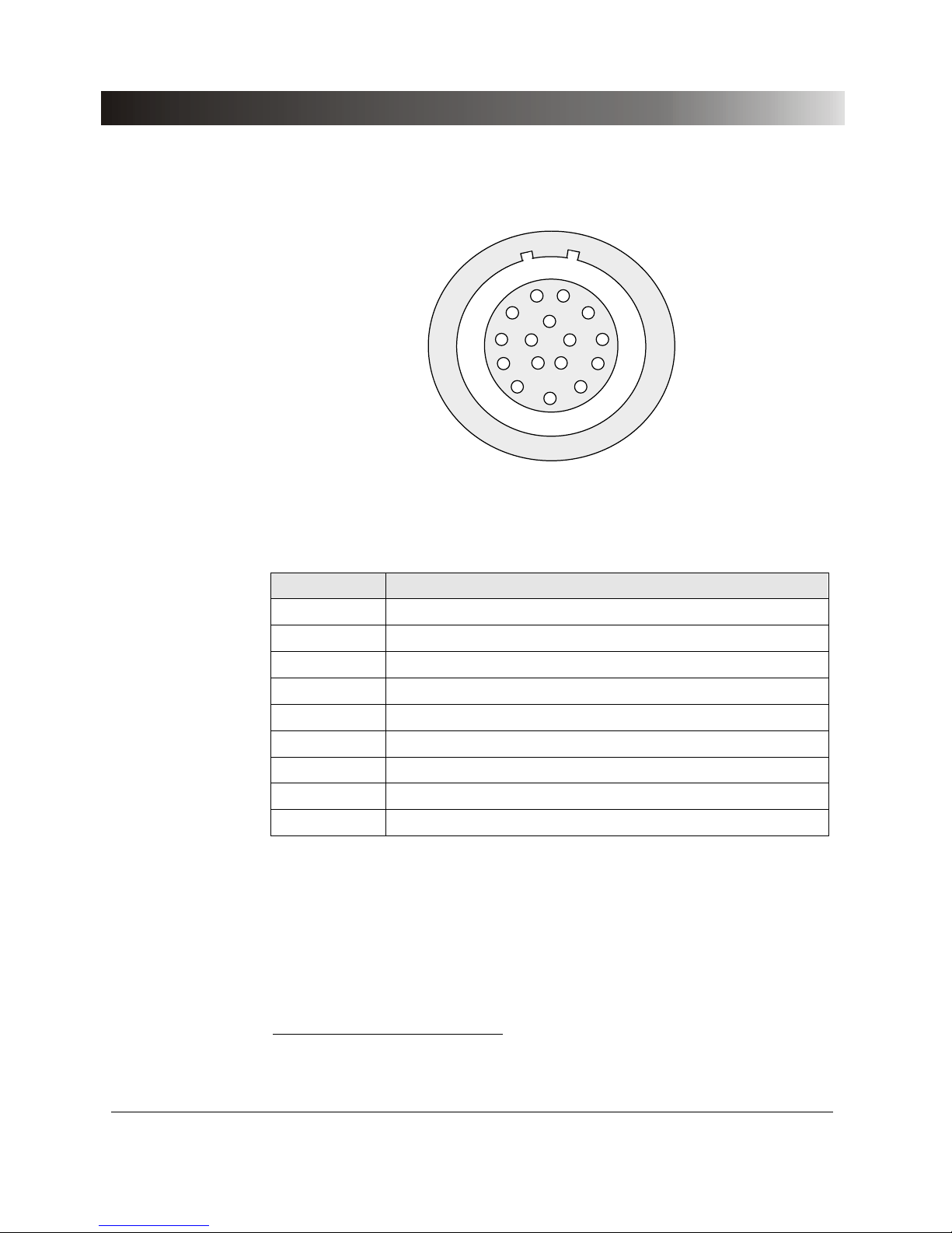
Test Set CMC 156
28
1
2
3
4
5
6
7
8
9
10
11
12
13
14 15
16
Figure 10 Plug for Interface "Gen. out 7-12" (lower 16-pole Lemo jack);
(view onto cable connection side)
Pin Function1
Pin 1 Gen. Out 7
Pin 2 Gen. Out 8
Pin 3 Gen. Out 9
Pin 4 GND_A (electrically connected to ground)
Pin 5 Gen. Out 10
Pin 6 Gen. Out 11
Pin 7 Gen. Out 12
Pin 8-16 for internal use
Housing shield connection
Table 7 Assignment
1
Gen. out 7-9 and Gen. out 10-12 each form a selectable triple (voltage or current system).
Page 29

Connectors and Interfaces
29
4.2.2 ext. Interface
On the connection socket ‘ext. Interf.’ two counter inputs are supplied for
meter testing with input frequencies of up to 100kHz. In addition, there are four
additional transistor binary outputs 11-14. Compared to the relay binary
outputs these have the advantage that they do not bounce and that only
minimal response times occur.
1
2
3
4
5
6
7
8
9
10
11
12
13
14 15
16
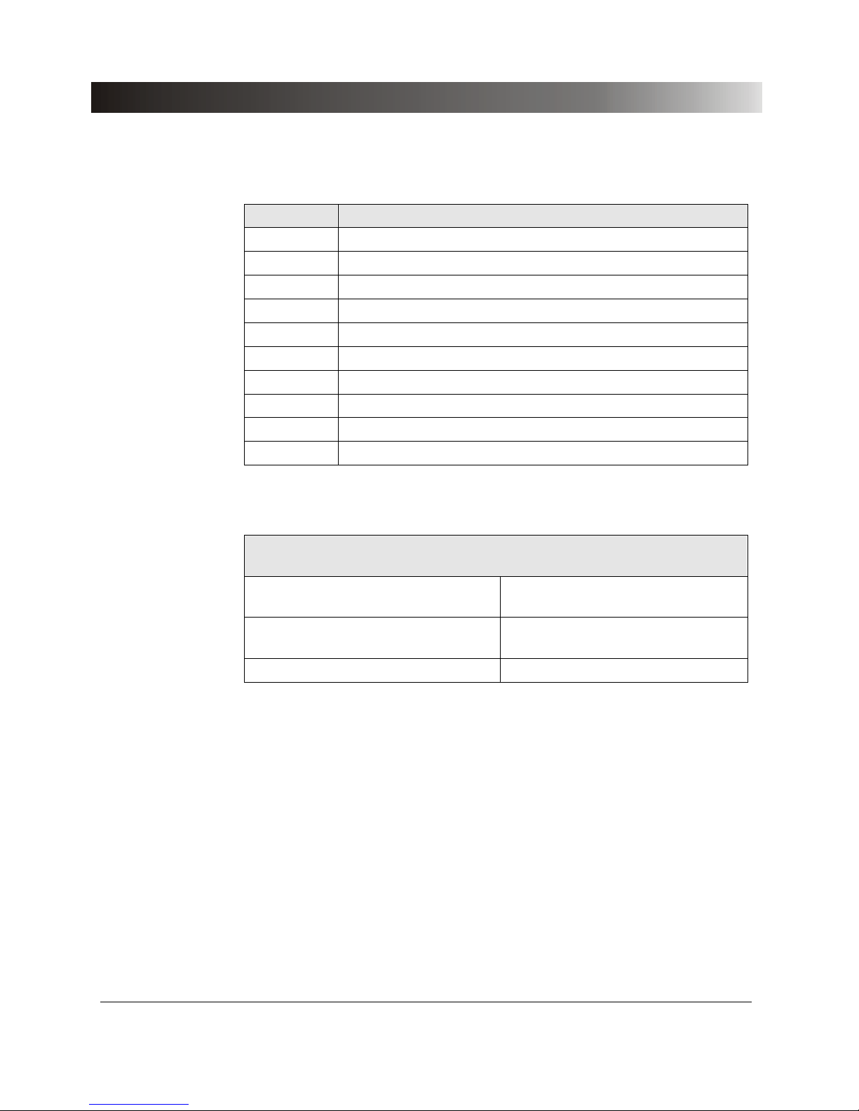
Figure 11 Plug for Interface "ext. Interface" (upper 16-pole Lemo jack);
(view onto cable connection side)
Page 30
Test Set CMC 156
30
Socket Function
Pin 1 Counter input 1
Pin 2 Counter input 2
Pin 3 Reserved
Pin 4 GND connected with GNDA (Gen. Out 7-12)
Pin 5 Binary output 11
Pin 6 Binary output 12
Pin 7 Binary output 13
Pin 8 Binary output 14
Pin 9-16 Reserved
Housing Shield connection
Table 8 Assignment
Manufacturer designation of plug for "Gen. out 7-12" and
"ext. Interface"
For Gen. out 7-12:
Plug with 2 guide cams and pull relief
FGB.2B.316.CLAD 72Z
For ext. Interface:
Plug with 1 guide cam and pull relief
FGG.2B.316.CLAD 72Z
Bend protection spout black GMA.2B.070 DN
Table 9 Manufacturer designation
If you want to order from OMICRON, refer to section 7.2"Ordering Notes “.
Page 31

Technical Data
31
5 Technical Data
The following data refer to a CMC 156 test set with standard design, without
external amplifiers.
For test sets with the EP option (Extended Precision), technical data
regarding the power amplifiers are different from the corresponding data of
standard devices: therefore, these data can be found separately in chapter 6,
"Technical Data EP Option".
• Guaranteed values:
- In general:
Valid for 1 year from factory calibration, within 23 °C ± 5 °C
(73 °F ± 10 °F) at nominal value and a warm-up time of > 25 min.
- Guaranteed values of generator outputs:
Valid in the frequency range 10 – 100 Hz.
• Accuracy specifications:
Valid in the frequency range DC – 100 Hz.
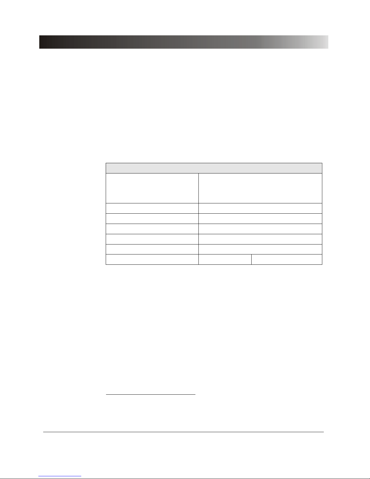
5.1 Mains Supply
Mains supply
Connector Plug acc. to IEC320
Voltage, 1-phase
Nominal voltage
Permissible range
110 to 240 Vac
99V to 264 Vac
Mains fuse T6.3 AH 250 V
Power consumption < 600 VA
Frequency
Nominal frequency
Permissible range
50 / 60 Hz
47 to 63 Hz
Table 10 Supply data
Page 32
Test Set CMC 156
32
5.2 Outputs
The data given in the following table are valid for all generator outputs,
regardless of the amplifiers used (internal or external ones); the following
tables are valid only for equipment with internal amplifiers.
For the block diagram of the generator outputs available please refer to
Figure 3 on page 18.
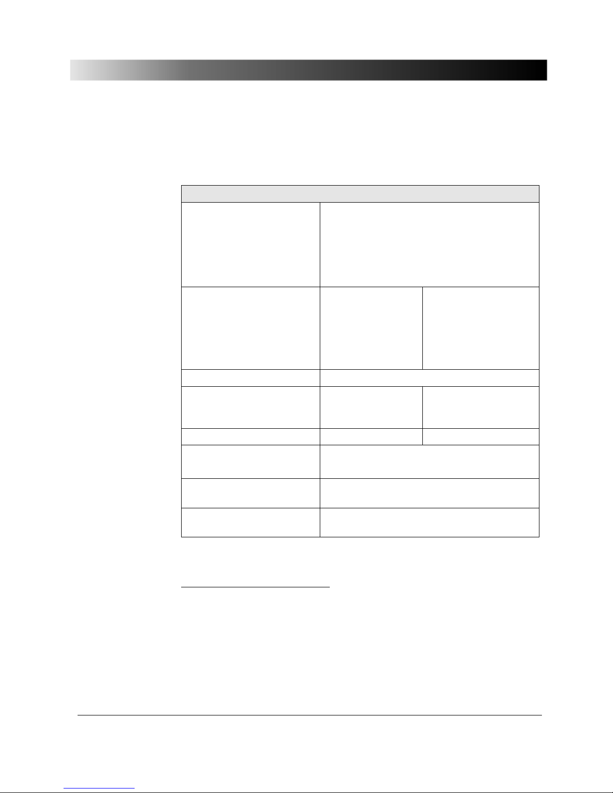
Analog current and voltage outputs
Frequency range 1
Sinusoidal signals
Transient signals
10 to 1000 Hz
DC to 3.1 kHz
Frequency resolution 5 µHz
Frequency accuracy 0.5 ppm
Frequency drift 1 ppm
Phase range - 360 ° to + 360 °
Phase resolution 0.001 °
Phase error 2 typ. 0.02 ° Guaranteed < 0.1 °
Table 11 Analog current and voltage outputs
1
If you purchased the option FL-6, the maximum output frequency is constrained to 599 Hz.
2
Valid for sinusoidal signals with 50 / 60 Hz.
Page 33
Technical Data
33
5.2.1 Current Outputs CURRENT OUTPUT 1-3
3 current outputs1 for standard design
Output currents
3-phase AC (L-N)
1-phase AC (L-N)
in parallel
1-phase DC (L-N)
3 × 0 to 12.5 A
1 × 0 to 12.5 A
1 × 0 to 21 A
1 × 0 to ±12.5 A
Power2
3-phase AC (L-N)
1-phase AC (L-L)
3
1-phase AC (L-N)
4
1-phase DC (L-N)
typ. 3 × 40 VA
typ. 1 × 80 VA
typ. 1 × 65 VA
typ. 1 × 62 W
guar. 3 × 37.5 VA
guar. 1 × 75 VA
guar. 1 × 62 VA
guar. 1 × 59 W
Resolution < 500 µA
Accuracy5 typical error
< 0.03 % rd.
+ 0.01 % of rg.
guaranteed error
< 0.08 % rd.
+ 0.02 % of rg.
Harmonic distortion6 typ. 0.03 % guar. < 0.07 %
Short-circuit protection
Open-circuit protection
Unlimited against N and from L to L.
Open outputs (idling) allowed.
Connection 4 mm banana sockets or amplifier
combination socket.
Isolation Reinforced isolation to mains and to all SELV
interfaces.
Table 12 Current outputs with standard design
1
Data for 3-phase systems are valid under symm. conditions (0 °, 120 °, 240 °).
2
For higher current or output power demands connection of an external amplifier is possible (e.g.
CMA current amplifier). The power data refers to an output current of 12.5 A
eff
or 12.5ADC.
3
Single-phase model (operation with two phases in phase opposition):
two currents in series, additional adapter SPA156 recommended.
4
2 phases (2 x 10.5 A) in parallel for in-phase operation.
5
rd. = reading; rg. = range, whereat n % of rg. means: n % of upper range value (1.25 or 12.5 A).
6
Values at 50/60 Hz, 20 kHz measuring band width, nominal value and nominal load.
Page 34
Test Set CMC 156
34
0
5
10
15
20
25
30
35
40
45
01122334455 6677889 910101111121213
I in A
P in V
A
Pt yp in [VA]
Pg a r i n [V A]
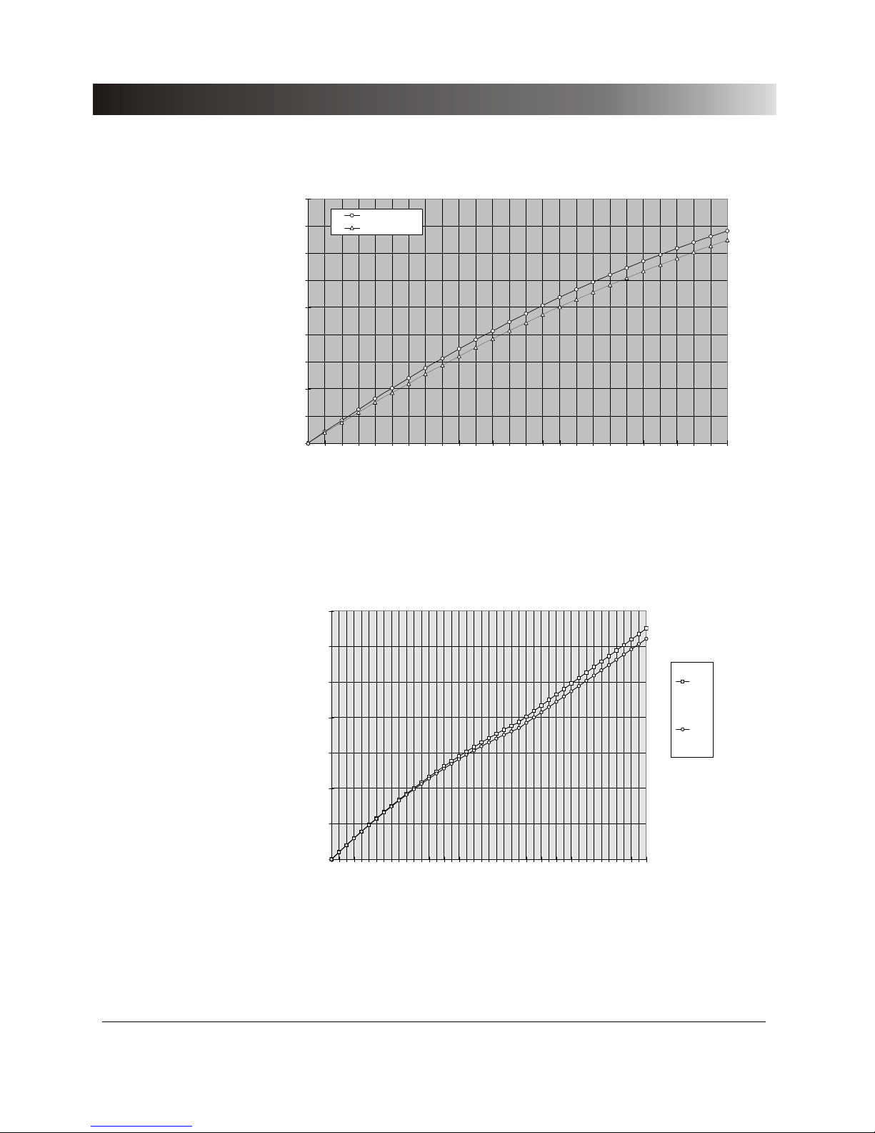
Figure 12 Typical (Ptyp.) and guaranteed (Pguar.) output power of the
internal current amplifiers with standard design
For a parallel connection of two current outputs a maximum output power of
Pout > 65VA
ac
is reached.
0
10
20
30
40
50
60
70
012345678
9
1011121314151617181920
21
I in A
P in V
A
1-ph.
typ.
1 ph.
guar.
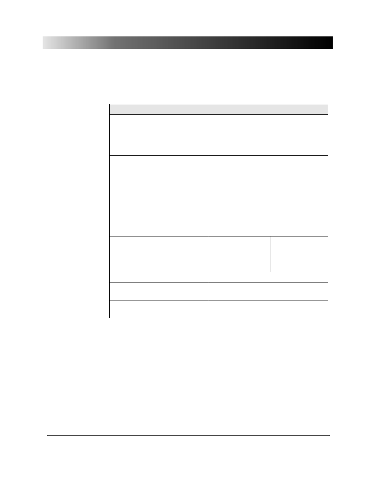
Figure 13 Typical (typ) and guaranteed (guar.) output power of the current
outputs for single-phase operation (two outputs in parallel) with
standard design
Page 35
Technical Data
35
5.2.2 Voltage Outputs VOLTAGE OUTPUT 1-3
3 voltage outputs for standard design 1
Output voltages
3-phase AC (L-N)
1-phase AC (L-L)
3-phase DC (L-N)
3 × 0 to 125 V
1 × 0 to 250 V
3 × 0 to ±125 V
Resolution 6 mV
Power2
3-phase AC
3
(L-N)
1-phase AC (L
1
-N/L3-N)
1-phase AC (L
2
-N)
1-phase AC (L-L)
1-phase DC (L
1
-N/L3-N)
1-phase DC (L
2
-N)
3 × 50 VA for 125 V
1 × 50 VA for 125 V
1 × 100 VA for 125 V
1 × 100 VA for 250 V
1 × 42 W for ± 60 to ± 125 V
1 × 90 W for ± 125 V
Accuracy4 typical error
< 0.03 % rd.
+ 0.01 % of rg.
guaranteed error
< 0.08 % rd.
+ 0.02 % of rg.
Harmonic distortion5 typ. 0.015 % guar. < 0.05 %
Short-circuit protection Unlimited against N and from L to L.
Connection 4 mm banana sockets or amplifier comb.
socket.
Isolation Reinforced isolation to mains and to all
SELV interfaces.
Table 13 Voltage outputs for standard designs
1
If not indicated otherwise, the voltages quoted are L-N.
2
Refer to output power curve in Figure 14
3
Data for three-phase systems are valid under symmetrical conditions (0°, 120°, 240°).
4
rd. = reading; rg. = range, whereat n % of rg. means: n % of upper range value (125V).
5
Values at 50/60 Hz, 20 kHz measuring band width, nominal value and nominal load.
Page 36
Test Set CMC 156
36
0
20
40
60
80
100
120
140
0,00 25,00 50,00 75,00 100,00 125,00
V (L-N) in Vr ms
Power in V
A
3 x sym. guar.
3 x sym. typ.
L2 only guar.
L2 only typ.
DC L2 only typ
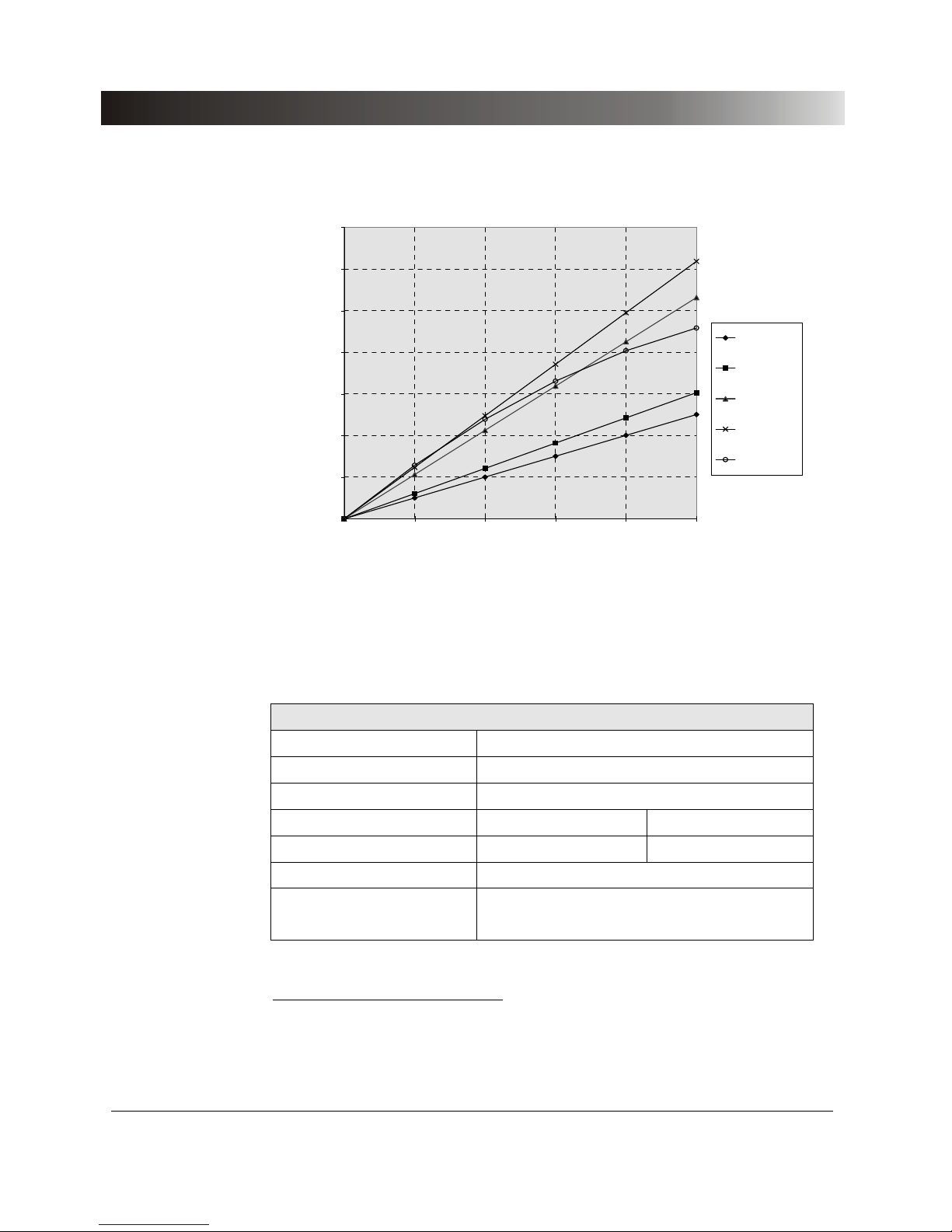
Figure 14 Typical (Ptyp) and guaranteed (Pmin) output power of the voltage
amplifiers1 with standard design
5.2.3 Interface for an External Amplifier ‘Gen. out 7-12’
6 outputs
Setting range 0 to 5 V
rms
Output current max. 2 mA
Resolution < 250 µV
Accuracy typ. error < 0.025 % guar. error < 0.05 %
Harmonic distortion2 typ. < 0.015 % guar. < 0.05 %
Short-circuit protection Unlimited against GND_A.
Isolation SELV isolated to all other potential groups.
Electrically connected to ground.
Table 14 Interface Gen. out 7-12
1
To obtain the specified power, in the test object parameters file (.TYP) in the CMC software the
corresponding voltage has to be set.
2
Values at nominal voltage (5V), 50/60 Hz and 20 kHz measuring band width.
Page 37
Technical Data
37
5.2.4 Binary Outputs Relays
4 Binary outputs relays (Binary outputs 1-4)
Type potential free contacts, software controlled
AC break capacity V
max
250 VAC; I
max
8 A; P
max
2000 VA
DC break capacity V
max
300 VDC; I
max
8 A; P
max
50 W
(see the following limit curve)
Inrush current 15 A (max. 4 sec. At 10 % ON period)
Electrical endurance 105 switching cycles at 220 Vac / 8 A; ohmic
Time to stable closed
condition
approx. 6 ms
Time to stable open condition approx. 10 ms
Bounce time approx. 0.5 ms
Connection 4 mm banana sockets
Isolation Functional isolation to power outputs.
Reinforced isolation to all SELV interfaces
and to mains.
Table 15 Binary outputs relays
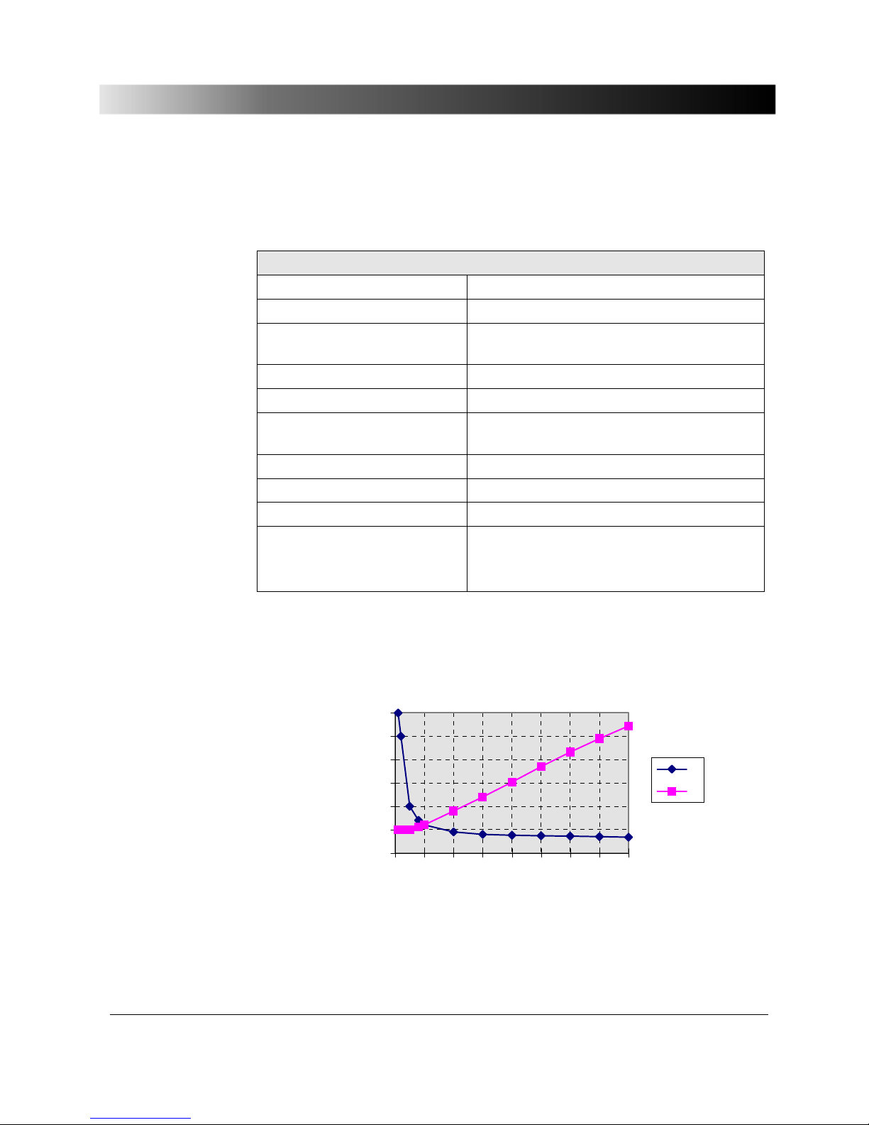
The following diagram shows the limit curve for direct voltage (for alternative
voltage a max. power of 2000 VA is achieved).
0
50
100
150
200
250
300
012345678
Current in A
Voltage in V / Power in
W
V
P
Figure 15 Limit curve of the relays of the binary outputs for direct voltage
Page 38
Test Set CMC 156
38
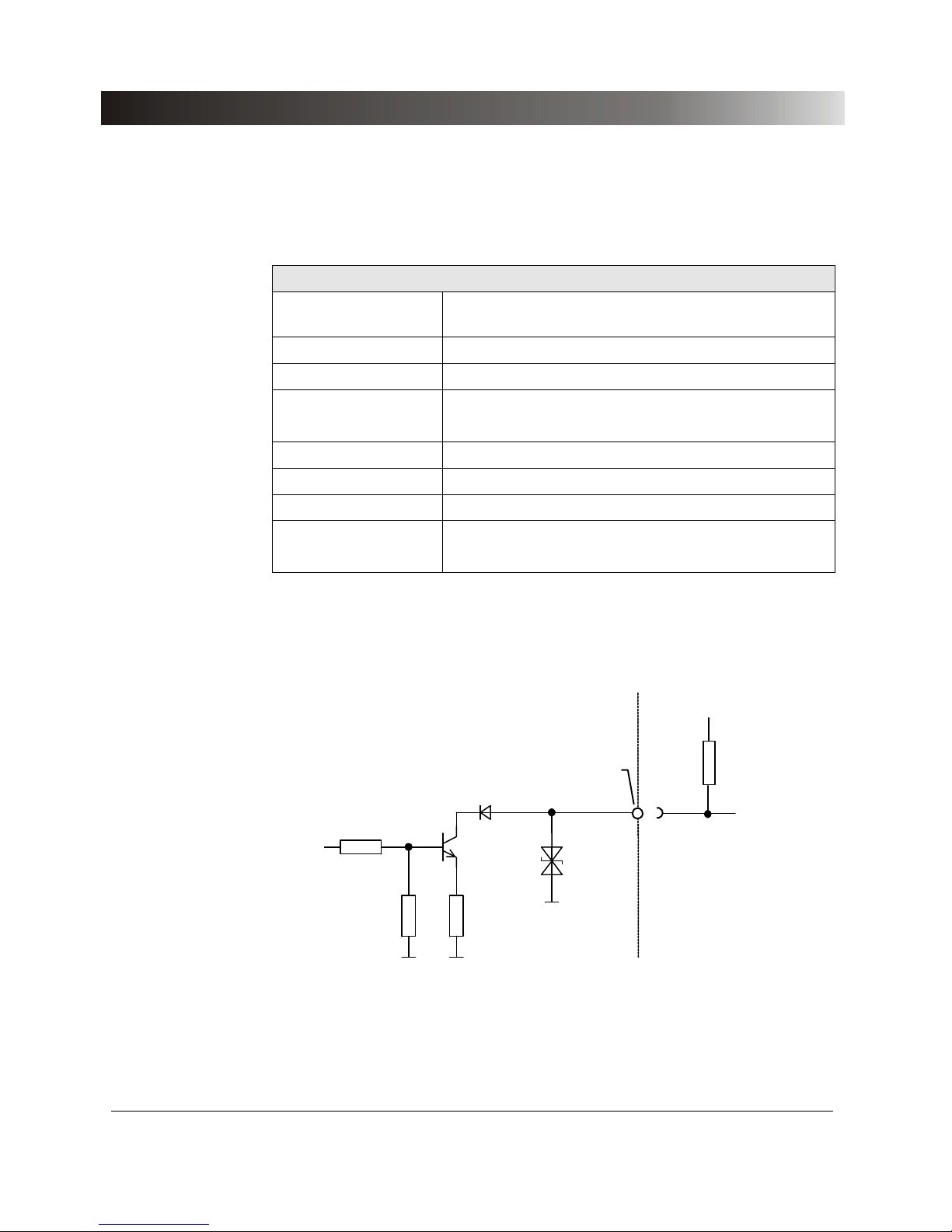
5.2.5 Binary Outputs Transistor
4 Binary outputs transistor (Binary outputs 11-14)
Type Open collector transistor outputs; external pull-up
resistor; see Figure 16.
Switching voltage max. 15V
max. input voltage. ±16V
Switching current max. 5 mA (current limited)
min. 100 µA
update time 100 µs
rise, fall time < 3 µs (V
external
= 5 V, R
pullup
=4k7)
Connector Socket "ext. Interf." (Back panel CMC 156)
Isolation SELV to all other potential groups of the test set.
Electrically
connected to Gen. Out 7-12 and ground.
Table 16 Binary outputs transistor
47Ω
6k8
22k
16V
Rpullup
Vexternal = 5 ...15V
CMC 156
Rear panel
Binary ouputs 11-14
ext. Interface
Figure 16: Binary outputs transistor 11-14 output module
Page 39

Technical Data
39
5.3 Inputs
5.3.1 Binary Inputs
10 Binary inputs
Response time typ. 220 µs (debounced)
Sampling rate < 100 µs
Measurement accuracy See Table 18 and Table 19
Counter function
Counting frequency
Pulse width
3 kHz (per input)
> 150 µs (for high and low signal)
Operating threshold for
potential-free operation
- Guaranteed 0:
input open or load against N > 100 k
Ω
- Guaranteed 1:
input short-circuited to N or
load against N < 20k
Ω
Operating threshold for
potential-sensing
operation
2 to 250 V
dc
to be set in the software
Hysteresis 0.36V ± 0.2V
Input resistance 70kΩ against reference potential (GND_BI)
Input capacity 10nF against reference potential (GND_BI)
Trigger criteria Switching of a potential-free contact or application
of direct voltage up to 250 V. Configurable
operating threshold.
Integration period 27 min
Connection 4 mm banana sockets
Isolation Functional isolation to power outputs and between
the two groups, with galvanic separation from each
other.
Reinforced isolation to all SELV interfaces and to
mains.
Configuration The binary inputs are configurable. Information
about binary input configuration is found in the
CMC software user's manual in Chapter 3
"Configuring the binary inputs”
Table 17 Binary inputs
Page 40
Test Set CMC 156
40
Time measurement on binary inputs
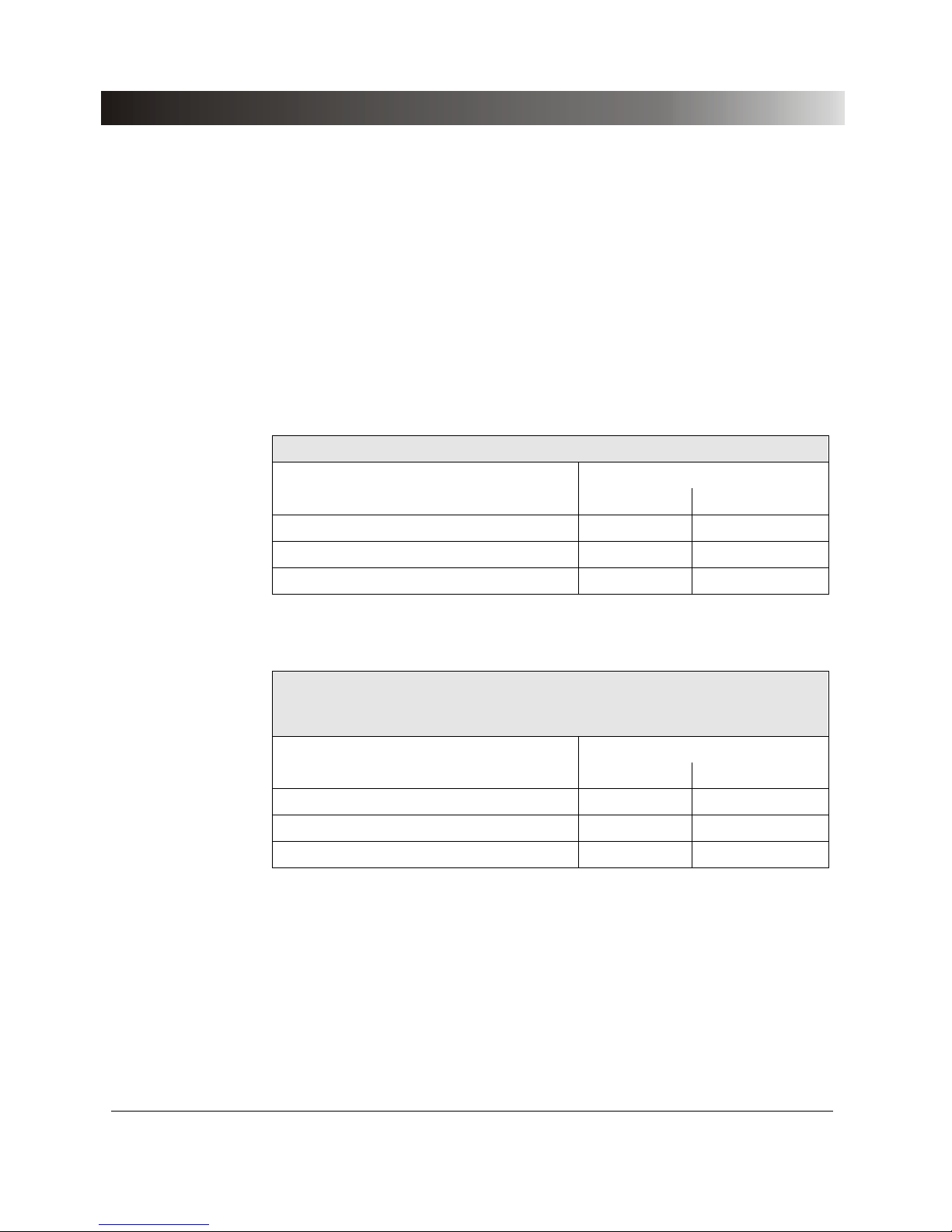
Due to the sampling rate and to the features of the input filters, a signal
present on binary inputs can only be sampled with a certain time tolerance.
All input binary signals are filtered on a period of 100 µs to remove possible
noise and therefore this time represents a delay in all measurements. As all
inputs are filtered in the same way, this delay does not appear when:
• we measure the difference between the switching times on two inputs, or
• we achieve synchronization between two devices.
Measurement accuracy when sensing a signal
Operating mode Time in µs
minimum maximum
Zero potential contact opening 200 400
Zero potential contact closing 110 220
Active signals 110 220
Table 18 Maximum accuracy for time measurements on one input
Measurement accuracy when assessing the difference between
switching times on two different inputs or when synchronizing two
devices (GPS)
Operating mode Time in µs
minimum maximum
Zero potential contact opening 0 200
Zero potential contact closing 0 120
Active signals 0 120
Table 19 Maximum accuracy for time measurements between two inputs or
during a synchronization
Page 41
Technical Data
41
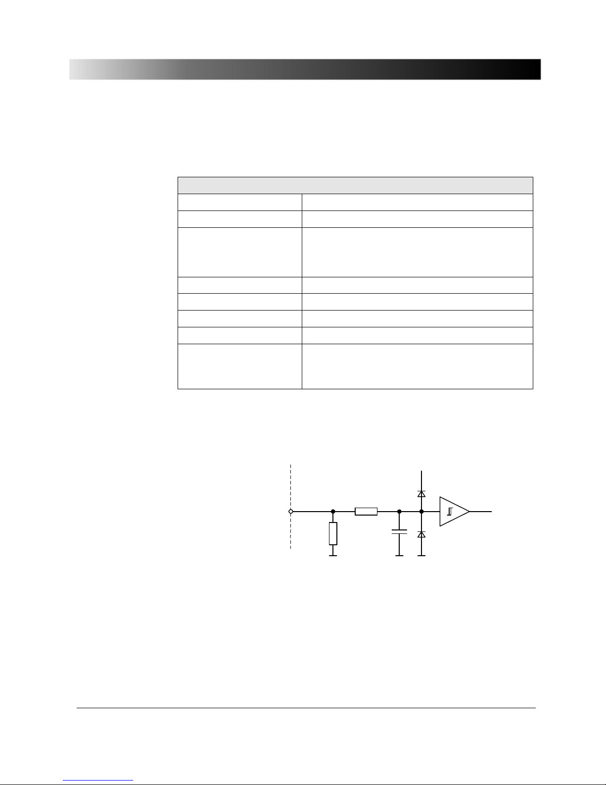
5.3.2 Counter Inputs 100 kHz
2 Counter inputs
max. counting frequency 100 kHz
Pulse width >3 µs (high and low signal)
Operating threshold
pos. edge
neg. edge
max. 8 V
min. 4 V
Hysteresis typical: 2 V
rise, fall time < 1 ms
max. input voltage ± 30 V
Connector Socket "ext. Interf." (rear panel CMC 156)
Isolation SELV to all other potential groups of the test set.
Electrically
connected to Gen. Out 7-12 and
ground.
Table 20 Counter inputs 100 kHz
Count er input 1..2
ext. Interface
+ 12V
100k
22k
47p
CM C 15 6
Bac k p anel
Figure 17 Input circuit of counter inputs 1, 2
Page 42
Test Set CMC 156
42
5.3.3 Measuring Inputs
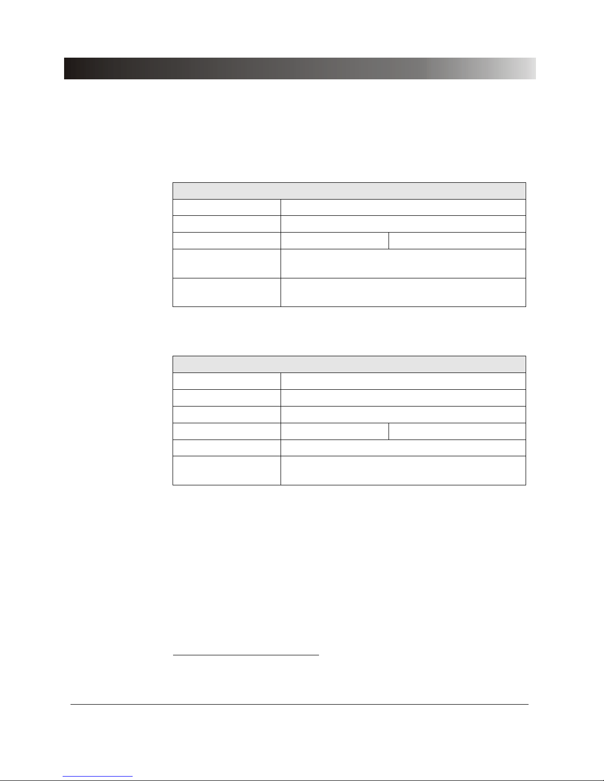
1 Direct current measuring input
Measuring range 0 to ± 20 mA
max. input current1 600 mA
Accuracy typ. error 0.01 % guaranteed error < 0.05 %
Connection 4 mm banana sockets
or measuring comb. socket.
Isolation Electrically connected to the current and voltage
power outputs.
Table 21 Direct current measuring input
1 Direct voltage measuring input
Measuring range 0 to ± 10 V
max. input voltage1 ±11 V
max. input current1 ± 90 mA
Accuracy typ. error < 0.01 % guaranteed error < 0.05 %
Connection 4 mm banana sockets or measuring comb. socket.
Isolation Electrically connected to the current and voltage
power outputs.
Table 22 Direct voltage measuring input
1
Exceeding this value may lead to destruction in the device.
Page 43
Technical Data
43
5.4 Computer Interface
25-pole SUB-D-plug
Designation Host Interface
Use The Host Interface (parallel interface) serves as
connection from the
CMC 156 test set to the
computer (LPT or USB).
If the computer is equipped with a parallel printer
port, too, use the 25-pole cable (VEHK0002) that
was supplied with the test set to connect the
CMC 156 to the computer.
If the computer is equipped with a USB port, use
an OMICRON
CMUSB-P converter (ordering
number VEHZ2007) instead of the VEHK0002 to
connect the
CMC 156 to the computer.
Isolation SELV isolated to all other potential groups;
electrically connected to ground.
Table 23 Computer interface
5.5 Ambient Conditions
5.5.1 Climate
Climate
Operating temperature 0 ... 50 °C (32 … 122 °F )
Storage and transport -25 ... +70 °C (-13 … 158 °F)
Humidity range 5 ... 95 % relative humidity; non condensing
Table 24 Climate
Page 44
Test Set CMC 156
44
5.5.2 Shock and Vibration
Dynamics
Vibration Tested according to IEC68-2-6 (operating mode)
frequency range 10 to 150 Hz; acceleration 2 g
continuous (20 m/s
2
); 10 sweeps, each axis.
Shock Tested according to IEC68-2-27 (operating mode)
15 g/11 ms, half-sine, each axis.
Table 25 Shock and Vibration
5.5.3 Electromagnetic Compatibility (EMC)
EMC
CE conformity The product complies to the normative document
about electromagnetic compatibility for
standardization of the laws of the member states of
the council of the European Union (EMC standard
89/336/EEC).
Emission
International
Europe
EN 50081-2
FCC Subpart B of Part 15 Class A
Susceptibility
International
Europe
EN 50082-2:1992
IEC 1000-4-2/3/4/6
Table 26 Electromagnetic Compatibility
Page 45
Technical Data
45
5.6 Safety
Safety standards and certificates complied with
European standards EN 61010-1:1993
EN 60950 +A1:1993-05
International standards IEC 1010-1
CAN/CSA-C22.2 No 1010.1-92
Certificates
UL/CSA certified up to test set serial
number
Pxnnnx.
(Example: a test set with serial
number
ND224C is UL/SCA-certified,
a test set with the serial number
QB111D not).
Table 27 Safety standards and certificates complied with
5.7 Mechanical Data
Dimensions and weight
Weight 9.8 kg (22.46 lbs)
Dimensions W x H x D (without handle) 343 × 145 × 268 mm
(13.5"
× 5.7" × 10.6")
Table 28 Dimensions and weight
Page 46

Test Set CMC 156
46
Page 47

Technical Data EP Option
47
6 Technical Data EP Option
The following technical data refer to power amplifiers integrated into devices
with the EP (Extended Precision) option.
Devices with EP option mainly differ from devices in standard design in the
following key features:
• specified accuracy on output power
• suitability to test of 0.2 class meters according to IEC687
• higher accuracy on power outputs
• higher output power
• two current ranges (from 0 to 12.5 A and from 0 to 1.25 A)
Technical data valid for a CMC 156 test set with standard design can be
found in chapter 5, "Technical Data".
Page 48
Test Set CMC 156
48
6.1 Outputs (EP option)
The power output specifications of test sets with EP option (Extended
Precision) may differ in substantial extent from the standard design. For the
standard design specifications, please refer to Paragraph 5.2 “Outputs”.
A block diagram of the generator outputs is given in Figure 3 on page 18.
Analog current and voltage outputs
Frequency range 1
Sinusoidal signals
Transient signals
10 to 1000 Hz
DC to 3.1 kHz
Frequency resolution 5 µHz
Frequency accuracy 0.5 ppm
Frequency drift 1 ppm
Phase range - 360 ° to + 360 °
Phase resolution 0.001 °
Phase error 2 typ. 0.005 ° Guaranteed < 0.02 °
Table 29 Analog current and voltage outputs
1
If you purchased the option FL-6, the maximum output frequency is constrained to 599 Hz.
2
Valid for sinusoidal signals with 50 / 60 Hz.
Page 49
Technical Data EP Option
49
6.1.1 Current Outputs CURRENT OUTPUT 1-3
3 current outputs1 range 12.5A
Output currents
3-phase AC (L-N)
1-phase AC (L-N)
in parallel
1-phase DC (L-N)
3
× 0 to 12,5 A
1
× 0 to 12, 5A
1
× 0 to 27 A at >45 Hz
1
× 0 to 21 A at <45 Hz
1
× 0 to ±12,5 A
Power2
3-phase AC (L-N)
1-phase AC (L-L)
3
1-phase AC (L-N)
4
1-phase DC (L-N)
typ. 3
× 43 VA
typ. 1
× 86 VA
typ. 1
× 65 VA
typ. 1
× 62 W
guar. 3
× 40 VA
guar. 1
× 75 VA
guar. 1
× 74 VA
guar. 1
× 59 W
Resolution < 500 µA
Accuracy5 typical error
< 0.015 % rd.
+ 0.005 % of rg.
guaranteed error
< 0.04 % rd.
+ 0.01 % of rg.
Harmonic distortion6 typ. 0.025 % guar. < 0.05 %
Short-circuit protection Unlimited against N and from L to L.
Open-circuit protection Open outputs (idling) allowed.
Connection 4 mm banana sockets or amplifier
combination socket.
Isolation Reinforced isolation to mains and to all SELV
interfaces.
Table 30 Current outputs, range 12.5 A (EP option)
1
Data for 3-phase systems are valid under symm. conditions (0 °, 120 °, 240 °).
2
For higher current or output power demands connection of an external amplifier is possible (e.g.,
CMA current amplifier). The power data refers to an output current of 12.5 A
eff
or 12.5 ADC.
3
Single-phase model (operation with two phases in phase opposition):
two currents in series, additional adapter SPA1 or SPA156 recommended.
4
3 phases (3 x 9 A) in parallel for in-phase operation.
5
rd. = reading; rg. = range, whereat n % of rg. means: n % of upper range value (12.5 A).
6
Values at 50/60 Hz, 20 kHz measuring band width, nominal value and nominal load.
Page 50
Test Set CMC 156
50
3 current outputs1 range 1.25A
Output currents
3-phase AC (L-N)
1-phase AC (L-N)
in parallel
1-phase DC (L-N)
3
× 0 to 1.25 A
1
× 0 to 1.25 A
1
× 0 to 3.75 A
1
× 0 to ±1.25 A
Power
3-phase AC (L-N)
1-phase AC (L-L)
2
1-phase AC (L-N)
3
typ. 3
× 5 VA
typ. 1
× 10 VA
typ. 1
× 15 VA
guar. 3
× 4.9 VA
guar. 1
× 9.8 VA
guar. 1
× 14.7 VA
Resolution < 50 µA
Accuracy4 typical error
< 0.015 % rd.
+ 0.005 % of rg.
guaranteed error
< 0.04 % rd.
+ 0.01 % of rg.
Harmonic distortion5 typ. 0.025 % guar. < 0.05 %
Short-circuit protection Unlimited against N and from L to L.
Open-circuit protection Open outputs (idling) allowed.
Connection 4 mm banana sockets or amplifier
combination socket.
Isolation Reinforced isolation to mains and to all SELV
interfaces.
Table 31 Current outputs, range 1.25 A
1
Data for 3-phase systems are valid under sym. conditions (0°, 120°, 240°).
2
Single-phase model (operation with two phases in phase opposition):
two currents in series, additional adapter SPA1 or SPA 156 recommended.
3
3 phases (3 x 1.25A) in parallel for in-phase operation.
4
rd. = reading; rg. = range, whereat n % of rg. means: n % of upper range value (1.25 A).
5
Values at 50/60 Hz, 20 kHz measuring band width, nominal value and nominal load.
Page 51
Technical Data EP Option
51
.
0.0
5.0
10.0
15.0
20.0
25.0
30.0
35.0
40.0
45.0
50.0
0.0
1.0
2.0
3.0
4.0
5.0
6.0
7.0
8.0
9.0
10.0
11.0
12.0
I in A
P in VA
Ptyp in [ VA]
Pgar in [ VA]
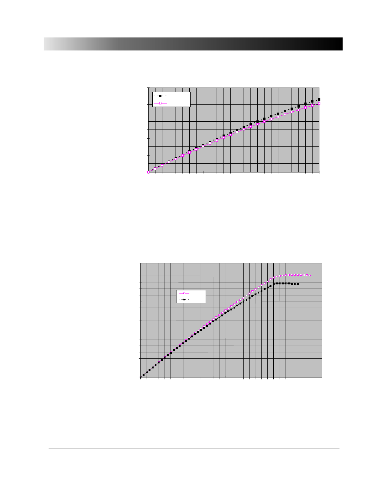
Figure 18 Typical (Ptyp.) and guaranteed (Pguar.) output power of the
internal current amplifiers in the 12.5 A range for EP option.
For a parallel connection of three current outputs a maximum output power of
Pout > 80 VA
ac
is reached.
Figure 19 Typical (typ) and guaranteed (guar) output power of the current
outputs for single-phase operation in the 12.5 A range for EP
option (three outputs in parallel).
0
5
10
15
20
25
30
35
40
45
50
55
60
65
70
75
80
85
90
I in A
P in VA
1-ph. typ.
1 ph. gar.
Page 52
Test Set CMC 156
52
0
1
2
3
4
5
6
0.00
0.05
0.10
0.15
0.20
0.25
0.30
0.35
0.40
0.45
0.50
0.55
0.60
0.65
0.70
0.75
0.80
0.85
0.90
0.95
1.00
1.05
1.10
1.15
1.20
1.25
I in A
P in VA
Ptyp in [VA]
Pguar i n [ VA]
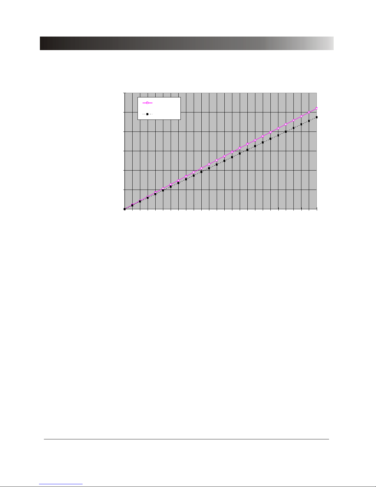
Figure 20 Typical (Ptyp.) and guaranteed (Pguar.) output power of the
internal current amplifiers in the 1.25 A range for option EP.
Page 53

Technical Data EP Option
53
6.1.2 Voltage Outputs VOLTAGE OUTPUT 1-3
3 voltage outputs
Output voltages
3-phase AC (L-N)
1-phase AC (L-L)
3-phase DC (L-N)
3
× 0 to 127.5V
1
× 0 to 255 V
(240 V
ac
+ 6 % or 230 Vac + 10 %)
3 × 0 to ± 127.5 V
Resolution 6 mV
Power1
3-phase AC (L-N)
2
1-phase AC (L
1
-N/L3-N)
1-phase AC (L
2
-N)
1-phase AC (L-L)
1-phase DC (L
2
-N)
guar.
3
× 50 VA for 125 V
1
× 60 VA for 125 V
1
× 100 VA for 125 V
1
× 140 VA for 255 V
1
× 90 W for ±125 V
typ.
3
× 60 VA
1
× 70 VA
1
× 140 VA
1
× 170 VA
1
× 93 W
Accuracy3 typical error
< 0.015 % rd.
+ 0.005 % of rg.
guaranteed error
< 0.04 % rd.
+ 0.01 % of rg.
Harmonic distortion4 typ. 0.015 % guar. < 0.05 %
Short-circuit protection Unlimited against N and from L to L.
Connection 4 mm banana sockets or amplifier comb.
socket.
Isolation Reinforced isolation to mains and to all
SELV interfaces.
Table 32 Voltage outputs for option EP
1
Refer to output power curve in Figure 21.
2
Data for 3-phase systems are valid under symm. conditions (0°, 120°, 240°).
3
rd. = reading; rg. = range, whereat n % of rg. means: n % of upper range value (127.5V).
4
Values at 50/60 Hz, 20 kHz measuring band width, nominal value and nominal load.
Page 54
Test Set CMC 156
54
0.0
20.0
40.0
60.0
80.0
100.0
120.0
140.0
160.0
0
5
1015202530354045505560657075808590
95
100
105
110
115
120
125
V in Veff
P in VA
3 x symm. t yp.
nur L2 belast et garantiert
nur L2 belast et typ.
DC nur L2 belast et typ
nu r L1 # L3 b el ast et gar .
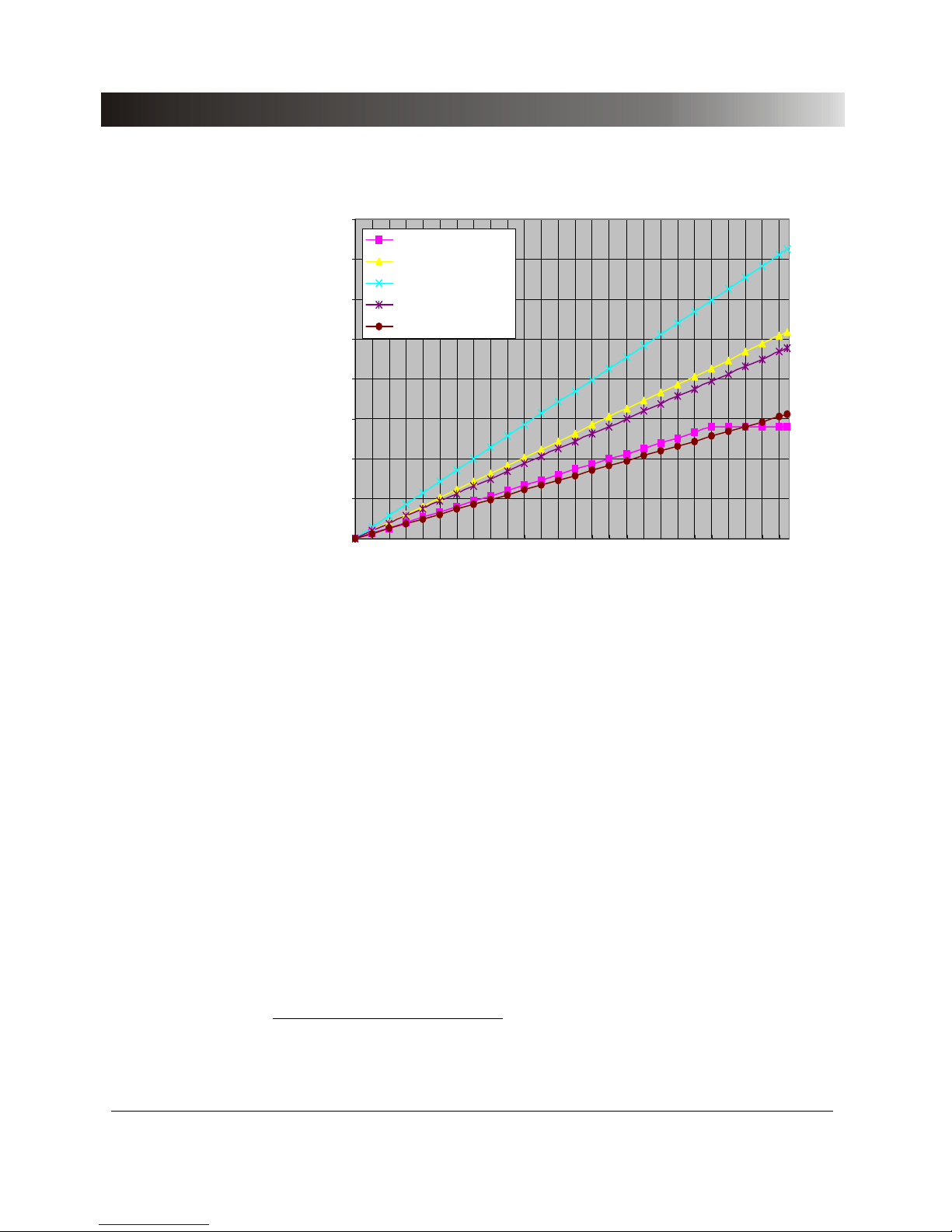
Figure 21 Typical and guaranteed output power of the voltage amplifiers
(option EP)
1
1
To obtain the specified power, in the test object parameters file (.TYP) in the CMC software the
corresponding voltage has to be set.
3 x symm. typical
burden on L2 only, guarant.
burden on L2 only, typical
DC, burden on L2 only, typ.
burden on L1 & L3, guarant.
Page 55
Technical Data EP Option
55
6.1.3 Output Power with EP option
The output power accuracy is defined only for the system CMC 156 with EP
option.
Output power accuracy
Accuracy1 (VA) 0.05 % typical; 0.1 % guaranteed
Temperature drift 0.005 % / ° C max.
Table 33 Output power accuracy
Limitations for obtaining an accuracy of 0.1% on output power
Output current ranges
Range 12.5 A
Range 1.25 A
1.25 to 12.5 A
0.1 to 1.25 A
Permissible load and current
Range 12.5 A
Range 1.25 A
0 to 0.5
Ω and 6 VA max.
at cos
ϕ from 0.5 to 1
0 to 1
Ω and 1 VA max.
at cos
ϕ from 0.5 to 1
Permissible load and voltage max. 10 VA
Output voltage range 50 to 125 VAC
Frequency range 50/60 Hz
Table 34 Limitations for obtaining an accuracy of 0.1 % on output power
1
Valid under the conditions stated in Table "Conditions for output power measurement".
Page 56

Test Set CMC 156
56
Page 57

Appendix
57
7 Appendix
7.1 Optional Devices
In this section optional devices to the OMICRON test set are listed. This
information is valid by the time of marketing the
CMC 156 test set.
7.1.1 Current Amplifier CMA 56
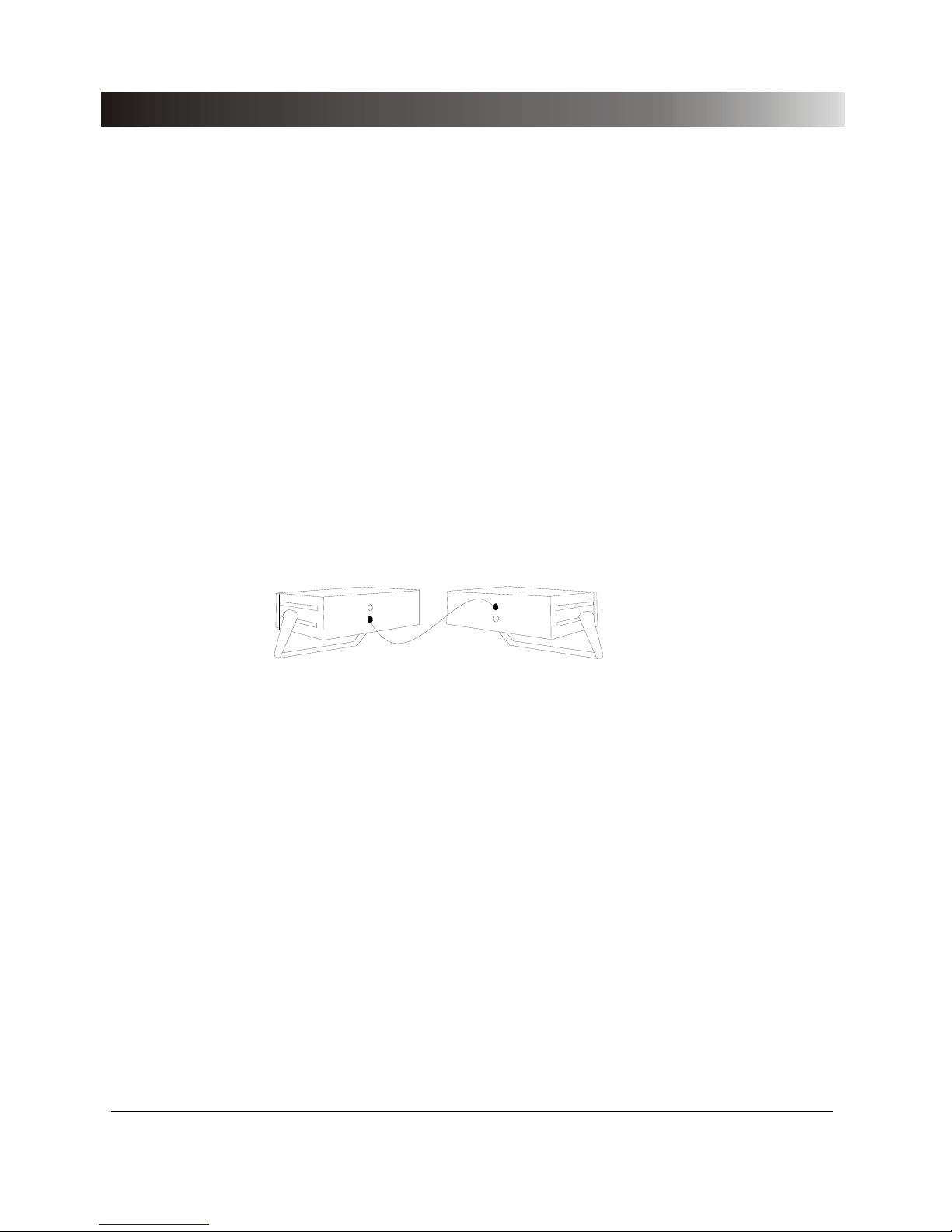
The CMA 56 is controlled via the CMC 156. The current amplifier is located in
the same compact housing as the
CMC 56 test set and supplies 3 × 50 A
rms
(max. 135 VA per phase).
Control is effected via an input jack on the back of the
CMA 56 via the
interface Gen. out 7-12 on the back of the
CMC 156:
Figure 22 Connection of the
CMA 56 current amplifier to the CMC 156 test
set
Using the
CMA 56 current amplifier, the OMICRON test system is able to test
relays having high requirements for power and current, so that a wide range of
possible test objects can be covered.
Additional information about the CMA 56 can be found in the CMA 56 manual.
CMA 56 current amplifie
r
CMC 156 test set
A
mpl. in
Gen. out
7-12
Page 58
Test Set CMC 156
58
7.1.2 Current Amplifier CMA 156
The 6-phase current amplifier CMA 156 serves as an additional device to the
CMC 156 test set, for tests that require:
• higher currents and/or higher power in the current path than is delivered by
the
CMC 156
• up to nine independent current phases.
The six current phases are arranged in two isolated groups and can be used
independently from the phases of the
CMC 156 (e.g. for differential protection
testing). By connecting the current phases in series, a power of up to 280 VA
can be output, which allows the testing of a wide range of electromechanical
relays.
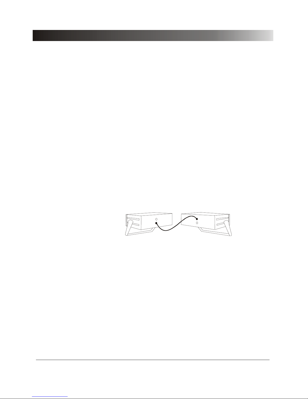
The
CMA 156 is connected via the interface Gen. out 7-12 on the back of the
CMC 156 test set:
Figure 23 Connection of the
CMA 156 current amplifier to the CMC 156 test
set
CMA 156 current amplifie
r
CMC 156 test set
A
mpl. in
Gen. out
7-12
Page 59

Appendix
59
Most important specifications of the CMA 156:
Output currents
6-phase AC 6 x 0 to 25 A
3-phase AC
1
3 x 0 to 50 A
DC 1 x 0 to
± 25 A
Power
6-phase AC 6 x 70 VA at 7.5 A
3-phase AC
1
3 x 140 VA at 15 A
1-phase AC (L-L)
2
1 x 140 VA at 7.5 A
1-phase AC (L-L)
3
1 x 280 VA at 7.5 A
DC (L-N) 1 x 140 W at 10.5 A
Weight 15.6 kg (34.4 lbs)
Dimensions without handle
W x H x D 450 x 145 x 390 mm (17.7"
× 5.7" × 15.4")
Additional information about the CMA 156 can be found in the CMA 156
manual.
1
By connecting the two amplifier groups in parallel.
2
Single-phase model: two current phases in series.
3
By connecting four amplifier phases in series.
Page 60
Test Set CMC 156
60
7.1.3 Voltage and Current Amplifier CMS 156
The voltage and current amplifier CMS 156 serves as an additional device to
the
CMC 156 test set, for tests that require:
• higher current or voltage than is delivered by the
CMC 156,
• higher power in the voltage or the current path than is delivered by the
CMC 156,
• up to six independent current or voltage phases.
The three voltage phases and the three current phases of the amplifier are
isolated from each other and can be used independently from the phases of
the
CMC 156. This allows testing of differential relays with six independent
current phases, or synchronizing devices with six independent voltage phases.
The higher power in the current path as well as voltage path extends the range
of electromechanical relays that can be tested.
The CMS 156 is connected via the interface Gen. out 7-12 on the back of the
CMC 156 test set:
Ampl. in
Gen. out
7-12
Figure 24 Connection of a
CMS 156 voltage and current amplifier to the
CMC 156 test set.
CMS 156 voltage and current amplifie
r
CMC 156 test set
Page 61

Appendix
61
Most important specifications of the CMS 156:
Output voltages
3-phase AC (L-N) 3 x 0 to 250 V
1-phase AC (L-L) 1 x 0 to 500 V
DC (L-N) 3 x 0 to
± 250 V
Voltage outputs power
3-phase AC (L-N) 3 x 75 VA at 75 to 250 V
1-phase AC (L-N) 1 x 150 VA at 75 to 250 V
1-phase AC (L-L) 1 x 150 VA at 150 to 500 V
DC (L-N) 1 x 212 W at
± 150 to ± 250 V
Output currents
3-phase AC 3 x 0 to 25 A
DC 1 x 0 to
±25 A
Current outputs power
3-phase AC (L-N) 3 x 70 VA at 7.5 A
1-phase AC (L-L)1 1 x 140 VA at 7.5 A
DC (L-N) 1 x 140 W at
±10.5 A
Weight 14.9 kg (32.8 lbs)
Dimensions without handle
W x H x D 450 x 145 x 390 mm (17.7"
× 5.7" × 15.4")
Additional information about the CMS 156 can be found in the CMS 156
manual.
1
Single-phase model: two current phases in series.
Page 62

Test Set CMC 156
62
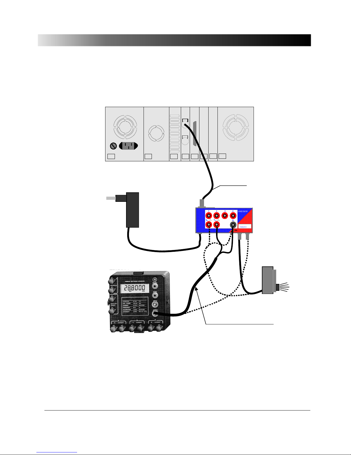
7.1.4 CMLIB B - Optional connection for meter testing
With the option CMLIB B it is easily possible to connect auxiliary equipment
needed for meter testing to a CMC test set.
The devices involved are:
• Test meter
• Reference meter
• Optical scanning head
Additional information about the CMLIB B can be found in the CMLIB B
manual.
Page 63
Appendix
63
Principle setup:
Optical head
e.g.:
SH2003
Wattmeter
Power supply
CMLIB B
VEHK0003
BNC to banana connection cable
VEHK0005
Page 64
Test Set CMC 156
64
7.2 Ordering Notes
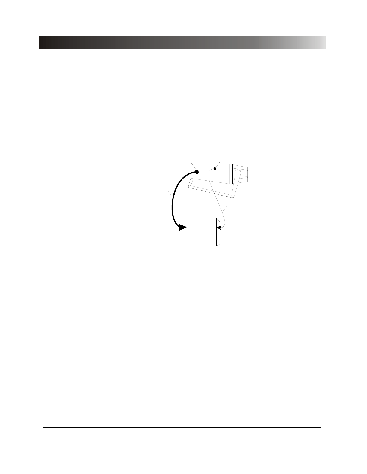
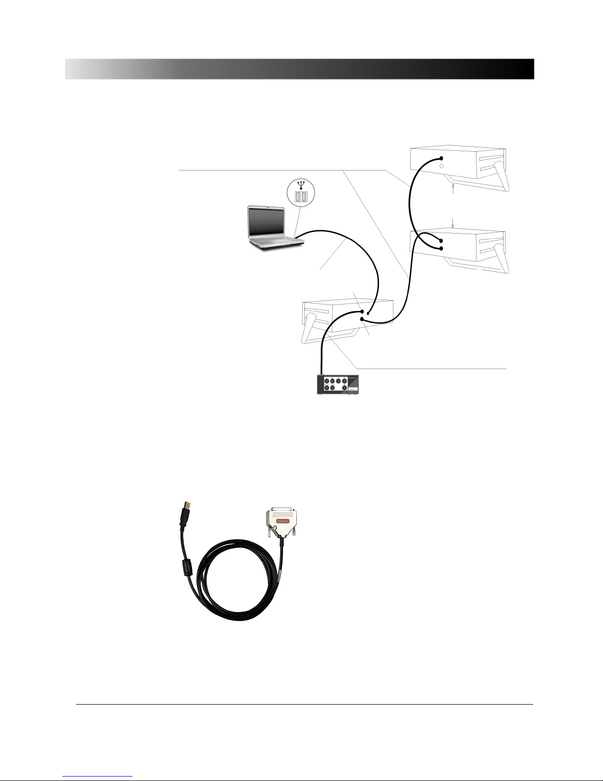
In this section ordering notes for additional devices and accessories to the
CMC 156 are found.
For easier identification of cables and plugs these items are represented
graphically below.
(Test object)
(CMC
test device)
Plug for
measuring combination socket
Plug for
generator combination socket
Generator cable
Measuring cable
Figure 25 Connection cables, plugs
Page 65
Appendix
65
Figure 26 Connection cables, plugs (continued)
*)
CMUSB-P converter (VEHZ2007):
Connecting cable CMC 156 – amplifier VEHK0003
Amplifier
(CMA, CMS)
Notebook
(USB)
Connection to computer via
CMUSB-P converter VEHZ2007
*)
CMC 156
A
mpl. in
A
mpl. in
A
mpl.out
ext. Interf.
Gen. out 7 - 12
Connecting cable CMC 156 – CMLIB B
VEHK0003
CMLIB B
Page 66
Test Set CMC 156
66
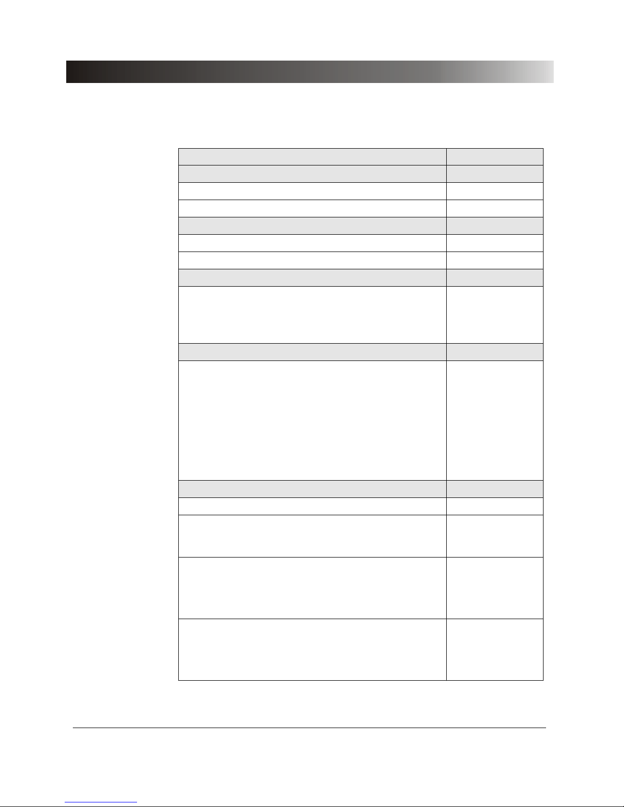
Ordering designation Ordering number
Amplifiers
CMA 156 current amplifier VEHV1010
CMS 156 voltage and current amplifier VEHV1030
Plugs
Plug for Generator Combination socket VEHS0103
Plug for Measuring Combination socket VEHS0104
Accessories
CMUSB-P
Converter for controlling a CMC 156 by a
computer with USB port (replaces VEHK0002;
see below).
VEHZ2007
Option FL-6
In a number of countries (e.g., Japan), the
export of multiphase generators able to output
steady signals with a frequency between
600 Hz and 2000 Hz is not permitted.
The FL-6 option constraints the maximum
fundamental frequency that the test set can
generate to 599 Hz. Test sets with the FL-6
option can therefore be exported without any
restrictions.
VEHO0599
Cables
Connection cable to CMC 156 to computer VEHK0002
Connection cable amplifier to CMC 156,
identical to connection cable CMC 156 to
CMLIB B.
VEHK0003
Generator cable
- 1st side Generator Combination plug, 8-pin
- 2nd side safety plugs 4 mm black
- 3 m (10 ft.) length, 8 x 2.5 mm²
VEHK0103
Measuring cable
- 1st side Lemo-plug, 20-pin
- 2nd side open (ends with connector sleeves)
- 3 m (10 ft.) length, 20 x 0.14 mm²
VEHK0104
Table 35 Ordering notes
Page 67
Appendix
67
Ordering designation Ordering number
CMLIB B (4mm sockets connector) VEHZ1102
Scanning devices for meters
SH2003 (reference from MTE company with
mechanical driving roller; also suited for
pulse outputs)
VEHZ2003
TVS6.15/1 (reference from MTE) for a meter
with pulse outputs only
VEHZ2004
Opto-Isolators (5 pieces)
CMC-OI-220 VEHZ0001
CMC-OI-110 VEHZ0002
CMC-OI-60 VEHZ0003
CMC-OI-24 VEHZ0004
CMC-OI-TTL VEHZ0005
Carrying bag
for CMC 156 (mini) VEHP0100
for CMA/CMS VEHP0010
Transport case
Case for CMA/CMS VEHP0011
Case for CMC 156/151 (mini) VEHP0101
Additional user manuals
CMC 156
(specify language when ordering)
VESD1002
Table 36 Ordering notes (continued)
Page 68

Test Set CMC 156
68
Page 69

Contact Information/Technical Support
69
8 Contact Information/Technical Support
North and South America
OMICRON electronics Corp. USA
12 Greenway Plaza, Suite 1510
Houston, TX 77046, USA
Phone: +1 713 830-4660 or
1 800 OMICRON
E-Mail: [email protected]
Web: www.omicronusa.com
Asia, Pacific
OMICRON electronics Asia Ltd.
Suite 2006, 20/F, Tower 2
The Gateway, Harbour City
Kowloon, Hong Kong S.A.R.
Phone: +852 2634 0377
E-Mail: [email protected]
Web: www.omicron.at
Europe, Africa, Middle East
OMICRON electronics GmbH
Oberes Ried 1
6833 Klaus, Austria
Phone: +43 5523 507-333
E-Mail: [email protected]
Web: www.omicron.at
For addresses of OMICRON offices with customer service centers. regional
sales offices or offices for training. consulting and commissioning please see
our website.
Page 70

Test Set CMC 156
70
Page 71

Index
71
Index
ϕ ............................................................ 32, 48
3
3dB-bandwidth .............................................. 13
5
599 Hz restriction ............................. 32, 48, 66
A
Accessoires
ordering notes on ...................................... 64
Accuracy ....................................................... 19
current outputs .................................... 33, 50
current outputs (EP) .................................. 49
I
DC
measuring input ................................... 42
interface to an external amplifier .............. 36
V
DC
measuring input ................................. 42
voltage outputs.......................................... 35
voltage outputs (EP) ................................. 53
Accuracy specifications ................................ 31
technical support;support
of manufacturer ......................................... 69
Amplifer
3-phase voltage and current amplifier ...... 60
Amplifers
6-phase current amplifier .......................... 58
Amplification errors ....................................... 19
Amplifier
configuring ................................................ 18
interface .................................................... 36
output power of the internal current
amplifiers ........................................ 34, 36
output power of the internal current
amplifiers (EP) .......................... 51, 52, 54
parallel connection of the outputs ............ 34
parallel connection of the outputs (EP) .... 51
protection of the current and voltage
outputs .................................................. 15
Amplifiers
current amplifier CMA 56 ......................... 57
ordering notes on ..................................... 64
Analog outputs ....................................... 32, 48
Assignment
Generator Combination connector ........... 23
interface to an external amplifier .............. 28
Interface to external amplifiers ................. 30
B
Back panel ................................................... 27
Bandwidth 3dB ............................................. 13
Basic values for transient signals ................ 17
Binary inputs
operating threshold .................................. 14
time resolution .......................................... 14
Binary inputs ................................................ 14
Binary inputs ................................................ 39
Binary outputs ........................................ 37, 38
break capacity .......................................... 37
Binary outputs transistor -
see CMLIB manual
Block diagram .............................................. 12
generator outputs ..................................... 18
Break capacity
binary outputs ........................................... 37
Page 72

Test Set CMC 156
72
C
Cables
ordering notes on ...................................... 64
CAN/CSA-C22.2 No 1010.1-92 .................... 45
Changing the mains fuse ................................ 4
Clicking when starting up ............................. 10
CMA
interface .................................................... 36
CMA 56 ......................................................... 57
CMS 156 voltage and current amplifer ......... 60
CMUSB-P converter ..................................... 65
Communication with the host computer ....... 13
Configuring external amplifiers ..................... 18
Connecting the system components .............. 9
Connection cable ............................................ 9
Control .......................................................... 11
Control of the hardware ................................ 13
Converter
D/A ............................................................ 13
Counter inputs .............................................. 41
Current amplifer
CMA 156 ................................................... 58
CMS 156 ................................................... 60
Current amplifier CMA 56 ............................. 57
Current outputs .................................32, 33, 48
external feeding ........................................ 15
protection .................................................. 15
Current outputs (EP)............................... 49, 50
D
D/A converter ................................................ 13
Data processing
measuring data ......................................... 11
DC measuring input ...................................... 42
Delivery contents ............................................ 9
Design .................................................... 11, 12
Digital signal processor ................................ 13
Digital-Analog converter ............................... 13
Dimensions ................................................... 45
Direct current measuring input ..................... 42
Direct voltage measuring input .................... 42
Disconnection temperature .......................... 15
Display ......................................................... 11
DSP .............................................................. 13
E
EN 61010-1/1993 ......................................... 45
Equipment grounding conductor .................... 4
European standards .................................... 45
ext. Interface ................................................ 29
External amplifers
CMA 156 .................................................. 58
CMS 156 .................................................. 60
External amplifier
interface .................................................... 36
plug assignment ....................................... 28
plug, assignment ..................................... 30
External amplifiers
3-phase current amplifier ......................... 57
External feeding to a current output ............ 15
F
Factory calibration ....................................... 19
Feeding to a current output .......................... 15
Filtering of the input signals ......................... 13
FL-6 option (599 Hz restriction) ....... 32, 48, 66
fNom ............................................................ 31
Frequency
accuracy ............................................. 32, 48
drift ..................................................... 32, 48
resolution ............................................ 32, 48
setting range ...................................... 32, 48
Front panel ................................................... 20
generator combination plug ..................... 22
Inputs ........................................................ 21
Front view .................................................... 20
Fuse ......................................................... 4, 31
Page 73

Index
73
G
Gen. out 7-12
assignment ................................................ 28
Assignment ............................................... 30
Generator Combination connector
Assignment ............................................... 23
Generator combination plug ......................... 22
Generator outputs
block diagram ........................................... 18
configuring ................................................ 18
Generators Combination connector
manufacturer designation ......................... 23
Grounding conductor ...................................... 4
Guaranteed values ....................................... 31
H
Hardware control .......................................... 13
Harmonic distortion
current outputs .................................... 33, 50
current outputs (EP) .................................. 49
interface to an external amplifier .............. 36
voltage outputs.......................................... 35
voltage outputs (EP) ................................. 53
Heat sink temperature when disconnecting . 15
Host-computer
communication with .................................. 13
HW test ......................................................... 10
I
IDC measuring input
direct current ............................................. 42
IEC 1010-1 ................................................... 45
IEC68-2-27 ................................................... 44
IEC68-2-6 ..................................................... 44
Initialization of the SW .................................. 10
Input signals
measurement and filtering ........................ 13
Inputs
binary .................................................. 14, 39
counter inputs ........................................... 41
front panel ................................................ 21
Installing the CMC 56 .................................. 10
Instructions for your safety ............................. 3
Internal amplifer
protection of the current and voltage
outputs .................................................. 15
Internal current amplifier
output power ...................................... 34, 36
output power (EP) ........................ 51, 52, 54
International standards ................................ 45
traceability ................................................ 19
I
out
................................................................. 33
I
out
(EP) ................................................... 49, 50
Isolation of the binary inputs ........................ 14
M
Mains fuse ................................................ 4, 31
Mains supply ................................................ 31
Manufacturer designation
Generator Combination connector ........... 23
measurement combination connector ...... 26
Manufacturers for plugs ............................... 26
Manufacturers of plugs ................................ 23
Measurement combination connector
manufacturer designation ........................ 26
Measurement of the input signals ................ 13
Measuring data processing ......................... 11
Measuring input
direct current ............................................ 42
direct voltage ............................................ 42
Measuring module ....................................... 14
Mechanical data ........................................... 45
Modules ....................................................... 12
Page 74

Test Set CMC 156
74
N
National standards........................................ 45
traceability ................................................. 19
Nominal frequency ........................................ 31
Nominal voltage ............................................ 31
binary inputs .............................................. 14
O
Operating threshold
binary inputs .............................................. 14
Operation ...................................................... 11
Opto-couplers ............................................... 14
Ordering notes .............................................. 64
Output frequency of transient signals ........... 17
Output power
current outputs .................................... 33, 50
Current outputs ......................................... 33
current outputs (EP) ............................ 49, 50
Current outputs (EP) ................................. 49
Output power of the internal current
amplifiers ............................................. 34, 36
Output power of the internal current
amplifiers (EP) ..............................51, 52, 54
Output signal path ........................................ 19
Outputs
analog ................................................. 32, 48
binary ........................................................ 37
binary outputs ........................................... 38
block diagram ............................................ 18
configuring ................................................ 18
current ....................................................... 33
current (EP) ............................................... 49
current outputs (EP) .................................. 50
interface to an external amplifier ............... 36
voltage ..................................................... 35
voltage (EP) .............................................. 53
Overtemperature
resulting in switching OFF ........................ 16
P
PC
communication with .................................. 13
Phase angle
ϕ ........................................ 32, 48
Phase error ............................................ 32, 48
Phase resolution .................................... 32, 48
Plugs
ordering notes on ..................................... 64
suppliers and manufacturers .............. 23, 26
Power
current outputs ................................... 33, 50
Current outputs ........................................ 33
current outputs (EP) ........................... 49, 50
Current outputs (EP) ................................ 49
Power consumption ..................................... 31
Power of the internal current
amplifiers ............................................ 34, 36
Power of the internal current
amplifiers (EP) .............................. 51, 52, 54
Power supply voltage
of the current amplifier ............................. 16
Principle block diagram ................................ 12
Processing of the measuring data ............... 11
Processor ..................................................... 13
Protection of the current and voltage
outputs ...................................................... 15
Page 75

Index
75
R
Range
voltage outputs (EP) ................................. 53
Rated (= nominal) voltage ............................ 31
Rated voltage
binary inputs .............................................. 14
Rear view ...................................................... 27
Reducing
power supply voltage of the current
amplifier ................................................. 16
Resolution
current outputs .................................... 33, 50
current outputs (EP) .................................. 49
interface to an external amplifier .............. 36
voltage outputs.......................................... 35
voltage outputs (EP) ................................. 53
voltage outputs (EP) ................................. 53
S
Safety............................................................ 45
Safety instructions .......................................... 3
Self-test ........................................................ 10
Setting range
frequency ............................................ 32, 48
interface to an external amplifier .............. 36
voltage outputs (EP) ................................. 53
Shock and Vibration ..................................... 44
Signal generation.................................... 13, 17
Signal path of the output signal .................... 19
Signal processor ........................................... 13
Signals
measurement and filtering ........................ 13
transients .................................................. 17
Specifications ............................................... 31
Specifications (EP) ....................................... 47
Standards ..................................................... 45
traceability ................................................. 19
Start up ........................................................... 3
Starting the SW up ....................................... 10
Storage temperature .................................... 43
Suppliers for plugs ....................................... 26
Suppliers of plugs ........................................ 23
Supply .......................................................... 31
Switching OFF
due to an overtemperature ....................... 16
System components ...................................... 9
connecting the ............................................ 9
System start ................................................... 9
T
Technical data ............................................. 31
Technical data (EP) ..................................... 47
Temperature when disconnecting ............... 15
Time resolution
binary inputs ............................................. 39
Time resolution of the binary inputs ............. 14
Traceability ................................................... 19
Transients
basic values ............................................. 17
frequency setting range ..................... 32, 48
output frequency ...................................... 17
Transport temperature ................................. 43
Trigger criterion
binary inputs ............................................. 39
Trigger threshold
Binary inputs ............................................ 14
U
UL 3111-1 .................................................... 45
Unaccuracy .................................................. 19
Page 76

Test Set CMC 156
76
V
VDC measuring input ..................................... 42
Ventilation slots ............................................ 10
Vibration and Shock ..................................... 44
View
front panel ................................................. 20
rear view ................................................... 27
VNom ............................................................ 31
Voltage amplifer
CMS 156 ................................................... 60
Voltage outputs .................................32, 35, 48
protection .................................................. 15
Voltage outputs (EP) .................................... 53
Voltage reference ......................................... 14
V
out
................................................................ 35
V
out
(EP) ........................................................ 53
W
Warranty ........................................................ 4
Weight .......................................................... 45
Wiring the system components ..................... 9
 Loading...