

Tuning Manual
OMEM200
www.omextechnology.com
200 Series ECU
OMEM200 Tuning Manual 3v10
0

OMEM200 Tuning Manual 3v10
1

OMEM200 Tuning Manual 3v10
1 Introduction ................................................................................................................. 4
1.1 What this manual covers ...................................................................................................................... 4
1.2 Notation Used in This Manual .............................................................................................................. 4
2 Software ...................................................................................................................... 5
3 Sensor Setup .............................................................................................................. 6
3.1 Throttle Position Sensor ....................................................................................................................... 6
3.2 MAP Sensor for Engine Load ............................................................................................................... 6
3.3 Coolant Temperature sensor ................................................................................................................ 7
3.4 Air Temperature sensor ........................................................................................................................ 8
3.5 Crank Sensor ........................................................................................................................................ 9
3.6 Trigger Wheel ....................................................................................................................................... 9
3.7 Ignition Timing Alignment ................................................................................................................... 11
4 Map Axes ................................................................................................................... 12
4.1 Engine Speed ..................................................................................................................................... 12
4.2 Engine Load ....................................................................................................................................... 12
5 Rev Limit ................................................................................................................... 13
6 Engine Start Condition ............................................................................................. 14
7 Idle ............................................................................................................................. 15
8 Conditions Corrections ............................................................................................ 17
8.1 Air Temperature .................................................................................................................................. 17
8.2 Coolant Temperature .......................................................................................................................... 17
9 Dwell Control............................................................................................................. 18
10 Dashboard ................................................................................................................. 19
10.1 Tacho .................................................................................................................................................. 19
10.2 Shift Light ............................................................................................................................................ 19
2

OMEM200 Tuning Manual 3v10
11 Password .................................................................................................................. 20
3

1 Introduction
Thank you for choosing Omex Engine Management. This manual is written to help the user through
the specifics of tuning the OMEM200 ECU. It is essential that the user reads all of the Omex
manuals before attempting to install the system and before attempting to start the engine.
Incorrect use of the Omex system could potentially lead to damage to the engine and personal
injury. If you have any doubts about fitting these parts or using the software then please contact
Omex for help.
As the system is computer based, technical support is given on the assumption that the user is able
to perform simple Windows based operations. The user will also need access to email as Omex will
nearly always require a copy of the calibration in the ECU to give support.
Omex may not be held responsible for damage caused through following these instructions,
technical, or editorial errors or omissions. If you have any doubts about fitting these parts or using
the software then please contact Omex for help.
1.1 What this manual covers
This manual covers the tuning of your Omex 200 ECU. Installation of the ECU and software use are
in-part covered, but there are separate manuals available that cover these topics in more depth.
1.2 Notation Used in This Manual
Menu commands are signified in bold type with a pipe symbol | between each level of the menu.
For example, File | Open indicates that you should click on the Open option in the File menu.
OMEM200 Tuning Manual 3v10
4

OMEM200 Tuning Manual 3v10
2 Software
Installing the software
Run SetupMAP4000.x.xx.xx.exe and follow the onscreen instructions.
Connection port
The ECU requires an RS232 serial connection. Desktop PCs and older laptops will have 9pin D
shaped ports on them marked COM for this type of communication. If you have this port then this is
the best to use for communication with the ECU. If your PC does not have one of these ports then
you will need to use an adapter. We suggest using the USB to RS232 adapter from ‘ATEN’ as the
software has been specifically designed for this adapter.
Connecting to the ECU
Ensure that if you are using an adapter, the drivers software from the adapter manufacturer has
been installed.
Join the data lead between the ECU and the PC
Open MAP4000 from the ‘Start bar’
ECU | Connection Setup and select your port from the list
ECU | Connect
Ignition ON (do not crank the engine)
The ‘Receiving Calibration’ bar will start moving across. When completed, you are connected to
the ECU.
Sending the startup calibration to the ECU
It is not possible to start a new calibration from File | New. Please contact Omex for a
suitable start-up calibration.
Save the start-up calibration from the start-up disk or email to the hard-drive in the location
Documents\OMEX\MAP4000\Calibrations. (note that this folder is only created when MAP4000
is opened for the first time so you must have opened MAP4000 on this PC before)
Connect to the ECU as described in the above section.
ECU | Send new calibration
Ignition ON (do not crank the engine)
Select your start-up calibration and press ‘open’
When the calibration has been sent to the ECU cycle ignition power OFF / ON
5
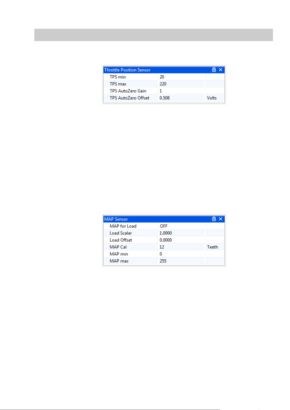
Load Scalar
The multiple of 1 that describes the theoretical 0-5V full scale of the
sensor.
Load offset
Most MAP sensors do not have 0V at 0KPa, they have a slight offset.
This option describes the offset.
3 Sensor Setup
3.1 Throttle Position Sensor
OMEM200 Tuning Manual 3v10
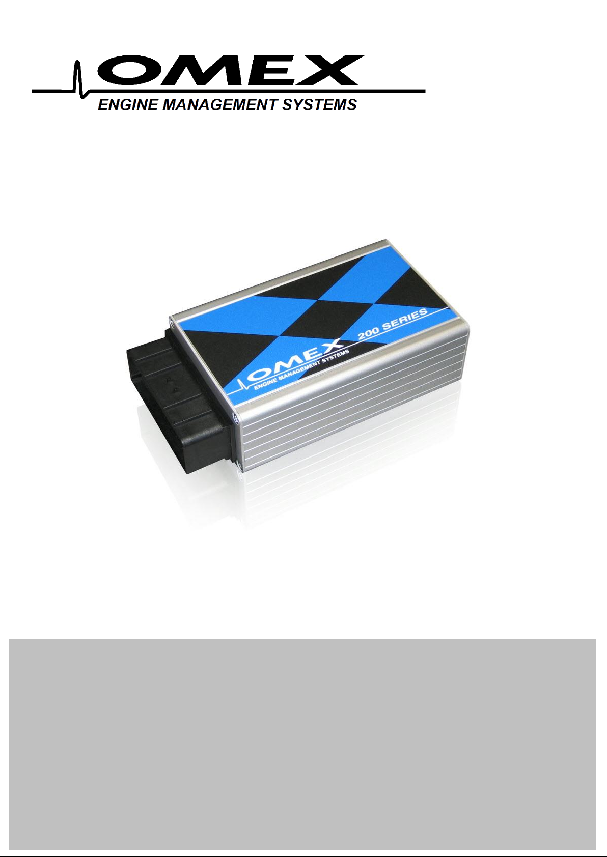
The parameter TPS raw gives the raw number output of the sensor which is scaled by options TPS
min and TPS max to give a throttle that works between 0 and 100%. To calibrate;
A live reading is shown for TPS raw. TPS raw will be between 0 and 255. The throttle position
sensor can often be rotated by the user. If so, the position should be set so that the sensor
never reaches 0 or 255 during its closed throttle to open throttle movement. It is preferable to
have the sensor set so that the values do not go close to either extreme. Typically a value of
approximately 20 at the idle position will give an acceptable value at WOT (wide open throttle).
The number for TPS raw at WOT needs to have 1 added to it, then be inputted to the options
box as TPS max (i.e. if TPS Raw is 220, then input 221). The number for TPS raw at the idle
position needs inputting to the options box as TPS min.
The Autozero options allow the ECU to automatically re-learn the idle position of the throttle sensor
every time the ECU is turned on. 0 disables this feature.
3.2 MAP Sensor for Engine Load
If you are using MAP for engine load sensing then set MAP for Load ON.
MAP min and MAP max should be 0 and 255. Do not change these unless instructed to by Omex.
MAP Cal is the time over which the ECU averages the MAP sensor input. Measured in internal
units. Typically 12.
As standard, the ignition map will show load values of 0-100KPa. This is not KPa, this is simply 0-
100% of the range of the sensor. It is possible to tell the ECU what range the sensor has so that you
can read the true KPa value on the maps.
Omex have the values for the sensors sold by Omex. If you want to calibrate your own sensor then
either find the voltage output information (total scale, and offset) from the manufacturer, or follow
this procedure;
6

Select a suitable start point for Load Scalar to suit your sensor e.g. for a nominally 2bar sensor,
enter 2.
Note the current value for MAP as Load.
Change the pressure at the sensor by a known amount using a vacuum pump.
Ignoring the absolute value, adjust Load Scalar until the correct change in value is shown by
MAP as Load to suit that pressure change e.g. if you have reduced the pressure by 50kPa,
then adjust Load Scalar until MAP as Load shows 50kPa less than it did before the pressure
change was made.
Remove the pressure change and try the above again. As this is an iterative procedure you may
need to do it several times before the correct change is shown on the ECU.
Remove any pressure changes from the sensor and adjust Load offset until MAP as Load
shows the current barometric air pressure.
3.3 Coolant Temperature sensor
OMEM200 Tuning Manual 3v10
The coolant temperature sensor used by the Omex ECU is a resistive sensor. The raw output of this
sensor is calibrated in the ECU to give the information in a more usable form, oC. Sensors are
calibrated in the Coolant Temp Sensor table. The values for many sensors are known but you may
need to calibrate your sensors.
To calibrate a sensor;
Place the sensor and a thermometer in a kettle or pan of water
The ECU will highlight the current raw input value from the sensor along the upper line of the
table. Below this input value, enter the current thermometer reading in degrees centigrade.
Heat the water. As the temperature increases, repeat the temperature readings.
When the water is fully heated, repeat the process as the water cools
7

Using the graph view, smooth the curve to remove any mistakes, and extrapolate to
unobtainable temperatures.
Coolant Fail Low and Hi are the failure points of the sensor and should be set to just within the
reading limits of the sensor.
Example- If the lowest temperature in the sensor table is –25 then Coolant Fail Low should be set
1 higher at –24. If the highest temperature in the sensor table is 125 then Coolant Fail Hi should be
set 1 lower to 124. Coolant Temp Default is the temperature to which the input defaults if the
sensor goes into failure.
3.4 Air Temperature sensor
OMEM200 Tuning Manual 3v10
The air temperature sensor used by the Omex ECU is a resistive sensor. The raw output of this
sensor is calibrated in the ECU to give the information in a more usable form, oC. Sensors are
calibrated in the Air Temp Sensor table. The values for many sensors are known but you may
need to calibrate your sensors.
To calibrate your sensor, see the calibration of the coolant temperature sensor.
Air Temp Fail Low and Hi are the failure points of the sensor and should be set to just within the
reading limits of the sensor.
Example- If the lowest temperature in the sensor table is –25 then Air Temp Fail Low should be set
1 higher at –24. If the highest temperature in the sensor table is 125 then Air Temp Fail Hi should
be set 1 lower to 124. Air Temp Default is the temperature to which the input defaults if the sensor
goes into failure.
8

3.5 Crank Sensor
The crank sensor input can be from either a Magnetic Variable Reluctance (MVR) sensor or a Hall
Effect sensor. The two types of sensor require different hardware on the ECU board, so are selected
by physical jumpers. This is covered in the installation manual.
Software changes must be made to suit the sensor type.
MVR
OMEM200 Tuning Manual 3v10
The crank sensor high and low gain settings allow a user definable change point for high sensitivity
to allow for low magnetic crank sensor outputs at low engine speeds. Typically the values are just
above idle speed.
Magnetic sensors can use either the rising or falling edge of the generated waveform. If the edge is
incorrect then the engine will misfire at some point in the engine speed range. There is also the
possibility that if the edge is incorrect on a magnetic sensor of the ignition timing on the engine
deviating from the ignition timing calculated by the ECU as the engine speed changes. To find the
correct edge either see which edge does / does not produce ignition timing changes, or using an
oscilloscope to look at the waveform. If the signal falls through the missing tooth section use Crank
Rising Edge, and if it rises through the missing tooth section use Crank Falling Edge.
Hall Effect
Hall effect sensors require values of 0 for the high and low gain settings as their output is the same
amplitude regardless of engine speed.
Hall Effect sensors can use either the rising or falling edge, though typically the falling edge would
be used.
3.6 Trigger Wheel
The pattern of teeth on the crank or flywheel that the crank sensor faces is known as a trigger
wheel. The pattern is evenly spaced teeth with missing or extra teeth as reference points. As
different manufacturers use different trigger patterns, the ECU is programmable to suit. The
information required in the ECU for many of the popular patterns is already known, some of which
are listed below. If you have a different pattern on your engine please contact Omex for advice.
It is very easy to make an engine run, but not run properly by incorrectly entering these
options and tables. If possible please contact Omex for a calibration aspect or email an
existing calibration to Omex to be changed to a different trigger pattern.
9

36-1
0 1 2 3 4 5 6 7 8 9 10
11
12
13
14
15
16
17
18
19
5 4 4 5 4 4 5 4 4 5 4 4 5 4 4 5 4 4 5
4
20
21
22
23
24
25
26
27
28
29
30
31
32
33
34
35
36
37
38
39
4 5 4 4 5 4 4 5 4 4 5 4 4 5 4 3 3 3 3
3
40
41
42
43
44
45
46
47
48
49
50
51
52
53
54
55
56
57
58
59
3 3 3 3 3 3 3 3 3 3 3 3 3 3 3 3 3 3 3
3
0 1 2 3 4 5 6 7 8 9 10
11
12
13
14
15
16
17
18
19 5 4 4 4 4 5 4 4 4 4 5 4 4 4 4 5 4 4 4 4
20
21
22
23
24
25
26
27
28
29
30
31
32
33
34
35
36
37
38
39 5 4 4 4 4 5 4 4 4 4 5 4 4 4 4 5 4 4 4 4
40
41
42
43
44
45
46
47
48
49
50
51
52
53
54
55
56
57
58
59 5 4 4 4 4 5 4 4 4 4 5 4 4 4 4 5 4 4 3 3
OMEM200 Tuning Manual 3v10
Tooth Control table:
60-2
Tooth Control table:
Rover K-Series (late)
10

0 1 2 3 4 5 6 7 8 9 10
11
12
13
14
15
16
17
18
19 4 4 5 4 4 5 4 4 5 4 4 5 4 5 4 5 4 4 5 4
20
21
22
23
24
25
26
27
28
29
30
31
32
33
34
35
36
37
38
39 4 5 4 4 5 4 4 5 4 5 4 5 3 3 3 3 3 3 3 3
40
41
42
43
44
45
46
47
48
49
50
51
52
53
54
55
56
57
58
59 3 3 3 3 3 3 3 3 3 3 3 3 3 3 3 3 3 3 3 3
Tooth Control table:
3.7 Ignition Timing Alignment
OMEM200 Tuning Manual 3v10
The ECU recognises the engine position by a missing or extra tooth on a pattern of evenly spaced
teeth. Different manufacturers have this reference in a different place on the trigger wheel so the
ECU needs to have adjustment for this. The numbers are known for most manufacturers and will be
set in the start-up calibration but if they are unknown or if you are using an Omex external 36-1
wheel, you will need to find this value yourself. To find this value you will need a strobe light and an
accurate TDC mark on the engine.
Hold the engine at 2000-3000 rpm (ie out of the idle condition where the ignition timing is stable)
Check the engine speed shown on the strobe light. Most strobe lights will see the wasted spark
on DIS systems and so will show double engine speed and so also double ignition timing. If this
is the case then halve all ignition timing figures shown on the strobe light.
Check the ignition timing with a strobe light and compare this number to the number in Target
Timing.
If the engine is retarded compared to Target Timing (the strobe light shows a lower value) then
advance the engine. If the engine is advanced compared to Target Timing (the strobe light
shows a higher value) then retard the engine. The larger buttons make larger changes, the
smaller buttons make smaller changes. The Target Timing on the PC will not change, but the
timing mark on the engine will move, so each adjustment will require the strobe light resetting.
Repeat these changes until the strobe light timing figure agrees with the Target Timing figure.
If you cannot get the engine to start and believe this is because the ignition timing is incorrect then
you can perform the above tests whilst cranking the engine. Timing lights will not work correctly
during normal cranking as the engine speed varies so much due to the compression of each
cylinder. Therefore the spark plugs should be removed (to remove compression), put back into the
HT leads, and placed onto an earthed part of the engine, then the process documented above can
be followed but at cranking speeds. When this is done and you get the engine started, it should be
repeated at normal running speeds.
11

4 Map Axes
4.1 Engine Speed
OMEM200 Tuning Manual 3v10
You can adjust this axis on the ignition map. Typically the RPM axis would have a value towards
stall as the first site (450rpm), a site just below the target idle speed, a site on the target idle speed,
a site just above the target idle speed, then the rest of the sites evenly spaced to complete the
engine speed range, the final site being just above the rev limit. On some engines it may be useful
to increase the density of sites around areas where the ignition requirements change rapidly e.g.
where an engine ‘comes onto cam’.
4.2 Engine Load
There are two choices for engine load reading;
Normal Aspirated
TPS for load (preference due to giving best throttle response and easy mapping)
MAP for load
Turbocharged / Centrifugal Supercharged
MAP for load
Positive Displacement Supercharged
TPS for load
MAP for load
TPS for load
The load axis will read kPa but this is actually 0-100% throttle. You can adjust the load axis on the
ignition map. Typically, the sites would be evenly spaced through the throttle range, maybe with
closer sites at light throttles.
MAP for load
You can adjust the load axis on the ignition map. The load axis of the map should have the lowest
site as the minimum MAP value on overrun, the next site up is the MAP value at warm idle, the top
site should be set to just above the maximum manifold pressure that will be run by the engine, then
the sites in between evenly spaced and maybe more densely placed below 100kPa than above.
12

OMEM200 Tuning Manual 3v10
5 Rev Limit
Set all of the throttle positions in the table to the same engine speed. An example of a 6000rpm limit
is as follows.
At this engine speed, a soft cut will be invoked. If the engine speed is exceeded by 50 rpm, then a
hard cut is invoked.
13

OMEM200 Tuning Manual 3v10
6 Engine Start Condition
The cranking condition is defined by the engine speed options Min RPM and Start Exit RPM. Min
RPM is the engine speed at which the engine is considered to start cranking (typically 50 rpm), and
Start Exit RPM is the engine speed above which the engine is considered to be under normal
running ie no longer cranking (typically 400rpm)
Whilst cranking, the ignition timing is determined by the Start Ignition option. This is set in degrees
and would normally be a low value eg 2 degrees.
14

OMEM200 Tuning Manual 3v10
7 Idle
The 200 series ECU controls idle using spark scattering.
The idle condition is entered by the options Idle on Below RPM, and Idle On Throttle. The engine
must be below both of these values to enter idle. The normal warm target idle speed that the ECU
attempts to maintain is set by Idle FB Target RPM.
A high idle will be required in some conditions. The ECU can set a high idle speed based on coolant
temperature (Idle Hi Below Cool), or as the engine enters the idle condition to give a ‘soft’ return to
idle (Idle Hi Time and Idle Hi Decay). The target idle increase above the normal idle speed for high
idle is Idle Hi FB Target+. When returning to the idle condition the target speed is the ‘Hi’ speed for
Idle Hi Time then reduced to the normal idle speed over a period of time set by Idle Hi Decay.
The Idle Scatter Spark Table shows the change in ignition timing based upon rpm away from the
target engine speed. When the engine speed is higher than target, negative values are required to
decrease the idle rpm, and when the idle is lower than target positive values are required to increase
the idle rpm. As the engine moves further away from the target speed, the numbers should increase.
Setting idle control
Turn the scatter spark control off by setting Idle On Below RPM to 100rpm so that the engine
will not enter the idle condition.
15

OMEM200 Tuning Manual 3v10
With the engine warm set the natural idle (through adjusting air bleed screws or if necessary,
the throttle stop, remembering that if the throttle stop is moved, TPS min must be reset) to
approximately 150rpm higher than the target idle speed.
Turn the scatter spark idle control back on by resetting the Idle On Below RPM option to its
previous value.
Blip the throttle and the engine speed should return to the Idle FB Target RPM value.
As the engine is being given more air than is required to idle the engine when warm it retards the
ignition whilst in the idle condition to maintain the target engine speed. When the engine is cold it
requires more air to idle and so it benefits from the extra air, the ignition is advanced whilst in the
idle condition, and the engine has an improved cold idle speed.
Setting high idle
With scatter spark control you simply set the Hi Idle options. As there is no idle motor to give the
engine extra air, the ECU will attempt to hold the Hi Idle speed, but will not be able to match it when
the engine is cold. Therefore, the high idle is only really used to give a gentle return to idle.
16

8 Conditions Corrections
8.1 Air Temperature
OMEM200 Tuning Manual 3v10
Ignition can be trimmed based upon air inlet temperature. This is only used for extremes of
temperature. This is described by the Air Temp Ign Trim table.
8.2 Coolant Temperature
Ignition can be trimmed based upon coolant temperature. This is only used for extremes of
temperature. This is described by the Coolant Ignition Trim table.
17

OMEM200 Tuning Manual 3v10
9 Dwell Control
The coil dwell time is set by option Coil Dwell Factor. This is a unitless value typically 20 - 25 for a
DIS coil pack. Charge times can be varied with respect to battery voltage and engine speed using
the Dwell vs Battery table and Dwell vs Speed table. Setting these table values to 100% gives a
constant dwell time.
The options Dwell max and Dwell min are the limits of dwell time regardless of calculated values
from the tables and coil factor option. These limits are measured in internal units. Contact Omex if
you want to change these values.
Calibrating dwell time
A startup calibration from Omex will have typical values for charge time alterations against battery
voltage and engine speed so you will normally only need to adjust the Coil Factor. You should use
the lowest value that still makes the greatest torque output from the engine.
18

10 Dashboard
10.1 Tacho
OMEM200 Tuning Manual 3v10
The frequency of pulses for the tacho is set by the option Tacho Teeth. Adjust this number until the
tacho reads the correct engine speed. The correct setting for a 4cylinder tacho is 3.
10.2 Shift Light
The engine speed at which the light is turned on is set by the option Shiftlight On RPM;
19

OMEM200 Tuning Manual 3v10
11 Password
Do not use the password features unless you have a particular requirement for it. If you
password-protect an ECU and lose the password, Omex CANNOT retrieve the calibration for
you. THERE IS NO ‘MASTER’ PASSWORD.
The ECU has security features that allow calibrations to be password protected. All Omex
calibrations are sent with the password cleared to allow all users access to the ECU. If you are using
security, clear the password at the beginning of a mapping session and set at the end. If setting a
password, keep notes of it and make sure that you have a copy of the last calibration in the ECU.
Setting a password
When connect to an ECU, a password may be set. To set a password;
Connect to the ECU
Select ECU | Security | Set Password...
A dialog box appears prompting for a password. The password may be any alphanumeric 6
character password.
Ensure that ‘Set as Default Password’ is NOT checked.
Enter a password and click OK.
Clearing a password
Once connected to a password protected ECU, the password may be cleared. Clearing the
password removes the security such that any PC can connect to this ECU.
To clear the password;
Connect to the ECU
Select ECU | Security | Clear Password...
Clearing a protected ECU
If using an ECU where the password is unknown it is possible to use the ECU. The information in
the ECU will be lost so the original calibration will never be accessed, and the ECU will instead be
filled with random numbers.
ECU | Connect
A dialog box appears prompting for a password.
20

OMEM200 Tuning Manual 3v10
As the password is unknown click Clear Calibration.
A dialog box appears asking if you wish to erase the calibration to allow access. Click Yes.
The PC will clear the ECU.
ECU | Send new calibration. Select your new start-up calibration.
Once the calibration has sent, cycle ignition off / on.
21
 Loading...